EP2063697A1 - Fold-in braided shield - Google Patents
Fold-in braided shield Download PDFInfo
- Publication number
- EP2063697A1 EP2063697A1 EP08169071A EP08169071A EP2063697A1 EP 2063697 A1 EP2063697 A1 EP 2063697A1 EP 08169071 A EP08169071 A EP 08169071A EP 08169071 A EP08169071 A EP 08169071A EP 2063697 A1 EP2063697 A1 EP 2063697A1
- Authority
- EP
- European Patent Office
- Prior art keywords
- housing
- support
- outer layer
- inner layer
- set forth
- Prior art date
- Legal status (The legal status is an assumption and is not a legal conclusion. Google has not performed a legal analysis and makes no representation as to the accuracy of the status listed.)
- Withdrawn
Links
- 239000010410 layer Substances 0.000 claims abstract description 80
- 239000002355 dual-layer Substances 0.000 claims abstract description 7
- 238000000034 method Methods 0.000 claims description 19
- 238000002788 crimping Methods 0.000 claims description 4
- 238000009954 braiding Methods 0.000 claims description 2
- 230000005670 electromagnetic radiation Effects 0.000 abstract description 13
- 229910052751 metal Inorganic materials 0.000 description 4
- 239000002184 metal Substances 0.000 description 4
- ATJFFYVFTNAWJD-UHFFFAOYSA-N Tin Chemical compound [Sn] ATJFFYVFTNAWJD-UHFFFAOYSA-N 0.000 description 3
- 239000000463 material Substances 0.000 description 3
- RYGMFSIKBFXOCR-UHFFFAOYSA-N Copper Chemical compound [Cu] RYGMFSIKBFXOCR-UHFFFAOYSA-N 0.000 description 2
- 229910000831 Steel Inorganic materials 0.000 description 2
- 229910052802 copper Inorganic materials 0.000 description 2
- 239000010949 copper Substances 0.000 description 2
- 230000007797 corrosion Effects 0.000 description 2
- 238000005260 corrosion Methods 0.000 description 2
- 239000010959 steel Substances 0.000 description 2
- 229910052782 aluminium Inorganic materials 0.000 description 1
- XAGFODPZIPBFFR-UHFFFAOYSA-N aluminium Chemical compound [Al] XAGFODPZIPBFFR-UHFFFAOYSA-N 0.000 description 1
- 230000003466 anti-cipated effect Effects 0.000 description 1
- 238000013459 approach Methods 0.000 description 1
- 238000010276 construction Methods 0.000 description 1
- 238000011161 development Methods 0.000 description 1
- 230000018109 developmental process Effects 0.000 description 1
- 238000012986 modification Methods 0.000 description 1
- 230000004048 modification Effects 0.000 description 1
- 230000001902 propagating effect Effects 0.000 description 1
- 238000004904 shortening Methods 0.000 description 1
- 239000007787 solid Substances 0.000 description 1
Images



Classifications
-
- H—ELECTRICITY
- H05—ELECTRIC TECHNIQUES NOT OTHERWISE PROVIDED FOR
- H05K—PRINTED CIRCUITS; CASINGS OR CONSTRUCTIONAL DETAILS OF ELECTRIC APPARATUS; MANUFACTURE OF ASSEMBLAGES OF ELECTRICAL COMPONENTS
- H05K9/00—Screening of apparatus or components against electric or magnetic fields
- H05K9/0007—Casings
- H05K9/0018—Casings with provisions to reduce aperture leakages in walls, e.g. terminals, connectors, cables
-
- H—ELECTRICITY
- H01—ELECTRIC ELEMENTS
- H01R—ELECTRICALLY-CONDUCTIVE CONNECTIONS; STRUCTURAL ASSOCIATIONS OF A PLURALITY OF MUTUALLY-INSULATED ELECTRICAL CONNECTING ELEMENTS; COUPLING DEVICES; CURRENT COLLECTORS
- H01R13/00—Details of coupling devices of the kinds covered by groups H01R12/70 or H01R24/00 - H01R33/00
- H01R13/648—Protective earth or shield arrangements on coupling devices, e.g. anti-static shielding
- H01R13/658—High frequency shielding arrangements, e.g. against EMI [Electro-Magnetic Interference] or EMP [Electro-Magnetic Pulse]
-
- H—ELECTRICITY
- H01—ELECTRIC ELEMENTS
- H01R—ELECTRICALLY-CONDUCTIVE CONNECTIONS; STRUCTURAL ASSOCIATIONS OF A PLURALITY OF MUTUALLY-INSULATED ELECTRICAL CONNECTING ELEMENTS; COUPLING DEVICES; CURRENT COLLECTORS
- H01R13/00—Details of coupling devices of the kinds covered by groups H01R12/70 or H01R24/00 - H01R33/00
- H01R13/648—Protective earth or shield arrangements on coupling devices, e.g. anti-static shielding
- H01R13/658—High frequency shielding arrangements, e.g. against EMI [Electro-Magnetic Interference] or EMP [Electro-Magnetic Pulse]
- H01R13/6591—Specific features or arrangements of connection of shield to conductive members
- H01R13/6592—Specific features or arrangements of connection of shield to conductive members the conductive member being a shielded cable
Definitions
- the present embodiments generally relate to a fold-in braided shield and a method of forming the fold-in braided shield.
- electromagnetic radiation can be generated from any number of sources, including natural phenomenon like lightning strikes, the emergence of electronic devices, and specifically telecommunication devices, has rapidly increased the amount of electromagnetic radiation propagating through the air.
- This external electromagnetic radiation can interfere with electronic devices by causing a current to flow through wires and other metallic objects. Since this extraneous current may generate unwanted signals, including a spike in current that can damage electronic components, some treat the rapid increase in electromagnetic radiation as a form of pollution.
- electromagnetic energy produced from internal electromagnetic sources, such as high current cables can also radiate out of the wire and interfere with other electronic devices.
- a way to combat these extraneous currents is to protect the wires of electronic devices from external electromagnetic radiation by using a braided metallic shield that covers and extends along the length of the wire.
- the braided metallic shield also prevents electromagnetic radiation from leaking out of the wire, reducing interference to external devices.
- a terminal end of the shield may include a solid metal support that is crimped to the shield. When the support is placed inside the shield, the terminal end of the shield is expanded, which separates the wires that form the braid in the shield, creating “holes.” Unfortunately, the "holes" provide a means for electromagnetic radiation to penetrate through the wire and interfere with transmitted signals on the wire.
- the terminal end of the shield ages, the wires that make up the shield may begin to unravel, causing additional "holes" in the shield.
- the unraveling weakens the crimp to the metal support, resulting in the braid having reduced pull strength.
- the terminal end of the shield as it begins to unravel, can cause galvanic corrosion between the shield and the metal support.
- a braid shield is needed that reduces or eliminates the number of holes in the shield to reduce or eliminate electromagnetic radiation into and out of the cable while providing a strong and consistent crimp with the support.
- a braided shield includes a housing having an outer layer and a support at least partially disposed in the housing and spaced from the outer layer.
- the housing further includes an inner layer integrally formed with the outer layer and disposed between the outer layer and the support to establish a dual-layer configuration.
- a method of forming the braided shield includes providing a housing having an end portion and defining a longitudinal axis and a passage extending along the longitudinal axis, compressing the end portion transverse to the longitudinal axis, and forcing the end portion into the passage to define the housing having an outer layer and an inner layer integrally formed with the outer layer.
- Figure 1 is a perspective view of a braided shield according to an embodiment
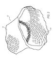
- Figure 2 is a perspective view of a housing having an outer layer and an inner layer integrally formed with the outer layer;
- Figure 3 is a cross-sectional side view of the braided shield of Figure 1 according to an embodiment.
- Figure 4 is a flow chart of a method of forming the braided shield according to an embodiment.
- a braided shield includes a housing having a dual-layer configuration.
- the housing is formed from a plurality of wires braided together and has an outer layer integrally formed with an inner layer to establish the dual-layer configuration.
- a support is at least partially disposed in the housing, and the inner layer is disposed between the support and the outer layer.
- the inner layer and outer layer reduce the amount of electromagnetic radiation that leaks into or out of the housing by reducing the number of holes in the housing.
- Forming the braided shield includes providing the housing, which defines a longitudinal axis and a passage extending along the longitudinal axis.
- the housing has an end portion, and the end portion is compressed transverse to the longitudinal axis. The end portion is then forced into the passage.
- the braided shield helps prevent the plurality of wires from unraveling and reduces corrosion between the housing and the support. Accordingly, the braided shield provided herein reduces or eliminates the number of holes in the shield to reduce or eliminate electromagnetic radiation from entering or exiting a cable while providing a strong and consistent crimp with the support.
- a cable may be useful in any industry or application, including, but not limited to, an electric vehicle's propulsion system wiring to prevent from a radio or other electronic sources.
- FIG. 1 is a perspective view of an exemplary embodiment of the braided shield 10 that includes a housing 12 with a dual-layer configuration.
- the housing 12 has an outer layer 14 and an inner layer 16 integrally formed to establish the dual-layer configuration.
- the outer layer 14 and the inner layer 16 need not be integrally formed. Instead, the inner layer 16 may be a separate piece that is inserted into the outer layer 14.
- the housing 12, including the outer layer 14 and the inner layer 16, may be formed from a plurality of wires braided together to block interference from electromagnetic radiation while remaining flexible.
- the housing 12 may be formed from any type of wire known, including, but not limited to, copper or copper coated with tin. As shown in Figure 1 , the housing 12 has a generally cylindrical shape, although it is to be appreciated that the housing 12 may be formed to any shape. Indeed, a portion of the housing 12 may have one shape and another portion of the housing 12 may have another shape. For instance, a portion of the housing 12 may have a generally cylindrical shape, while another portion of the housing 12 may have a generally elliptical shape. In either embodiment, the housing 12 defines a longitudinal axis 18 extending along a length of the housing 12. The housing 12 further defines a passage 20 through the length of the housing 12 along the longitudinal axis 18.
- a support 22 is at least partially disposed in the passage 20 of the housing 12.
- the support 22 has a relatively rigid structure for generally retaining the shape of the housing 12 when assembled.
- the support 22 may be formed from any known material.
- the support 22 may be formed from steel or aluminum.
- the support 22 may be coated with a metal such as tin. It is to be appreciated that the support 22 may be formed from or coated with other materials known in the art.
- a crimp band 24 is disposed on the outer layer 14 for securing the support 22 to the housing 12.
- the crimp band 24 may be formed from any material known in the art.
- the crimp band 24 may be formed from steel and plated with tin.
- the crimp band 24 includes at least one crimp end 26 that may be compressed, effectively shortening the circumference of the crimp band 24. When the crimp end 26 is compressed, the crimp band 24 holds the housing 12 and the support 22 together.
- Figure 2 is a perspective view of an exemplary embodiment of the housing 12.
- the inner layer 16 is integrally formed with the outer layer 14. Since the inner layer 16 is integrally formed with the outer layer 14, the inner layer 16 is also formed from the plurality of wires braided together.
- Figure 3 is a cross-sectional side view of an exemplary embodiment of the braided shield 10.
- the inner layer 16 is folded into the outer layer 14 to establish the dual-layered configuration.
- the outer layer 14 has an exposed surface 28 and an internal surface 30.
- the support 22 is disposed in the passage 20 spaced from the internal surface 30 of the outer layer 14.
- the inner layer 16 is disposed at least partially between the outer layer 14 and the support 22.
- the inner layer 16 has an exposed surface 32 and an internal surface 34. At least a portion of the internal surface 34 of the inner layer 16 is disposed on at least a portion of the internal surface 30 of the outer layer 14.
- the internal surface 30 of the outer layer 14 is the same as the internal surface 34 of the inner layer 16.
- the support 22 is disposed on the exposed surface 32 of the inner layer 16.
- the inner layer 16 defines at least a portion of the passage 20, and the support 22 is disposed on the internal surface 34 of the inner layer 16 inside the passage 20.
- the support 22 may further include a lip 36 integrally formed with and extending from the support 22 transverse to the longitudinal axis 18.
- the lip 36 limits movement of the support 22 along the longitudinal axis 18.
- the lip 36 may also align the crimp band 24 with the end of the housing 12.
- FIG 4 is a flowchart of an exemplary embodiment of a method 100 of forming the braided shield 10.
- the method 100 includes a step 102 of providing the housing 12 having an end portion and defining the longitudinal axis 18 and the passage 20 extending along the longitudinal axis 18.
- Providing the housing 12 may include braiding a plurality of wires to form the housing 12 and/or designating a portion of the housing 12 as the end portion.
- the method 100 also includes a step 104 of compressing the end portion transverse to the longitudinal axis 18.
- the method 100 includes a step 106 of forcing the end portion into the passage 20 to define the housing 12 having an outer layer 14 and an inner layer 16 integrally formed with the outer layer 14.
- the step 106 of forcing the end portion into the housing 12 may include compressing the housing 12 along the longitudinal axis 18, expanding the outer layer 14, and/or folding the inner layer 16 into the passage 20.
- the method 100 may include a step 108 of inserting the support 22 into the passage 20. Once the support 22 is inserted, the method 100 may include a step 110 of crimping the housing 12 onto the support 22. Crimping the housing 12 may include clamping the crimp band 24 onto the housing 12.
Landscapes
- Engineering & Computer Science (AREA)
- Microelectronics & Electronic Packaging (AREA)
- Shielding Devices Or Components To Electric Or Magnetic Fields (AREA)
Abstract
Description
- The present embodiments generally relate to a fold-in braided shield and a method of forming the fold-in braided shield.
- Although electromagnetic radiation can be generated from any number of sources, including natural phenomenon like lightning strikes, the emergence of electronic devices, and specifically telecommunication devices, has rapidly increased the amount of electromagnetic radiation propagating through the air. This external electromagnetic radiation can interfere with electronic devices by causing a current to flow through wires and other metallic objects. Since this extraneous current may generate unwanted signals, including a spike in current that can damage electronic components, some treat the rapid increase in electromagnetic radiation as a form of pollution. In addition, electromagnetic energy produced from internal electromagnetic sources, such as high current cables, can also radiate out of the wire and interfere with other electronic devices.
- One way to combat these extraneous currents is to protect the wires of electronic devices from external electromagnetic radiation by using a braided metallic shield that covers and extends along the length of the wire. The braided metallic shield also prevents electromagnetic radiation from leaking out of the wire, reducing interference to external devices. A terminal end of the shield may include a solid metal support that is crimped to the shield. When the support is placed inside the shield, the terminal end of the shield is expanded, which separates the wires that form the braid in the shield, creating "holes." Unfortunately, the "holes" provide a means for electromagnetic radiation to penetrate through the wire and interfere with transmitted signals on the wire. Also, as the terminal end of the shield ages, the wires that make up the shield may begin to unravel, causing additional "holes" in the shield. In addition, the unraveling weakens the crimp to the metal support, resulting in the braid having reduced pull strength. Finally, the terminal end of the shield, as it begins to unravel, can cause galvanic corrosion between the shield and the metal support.
- Accordingly, a braid shield is needed that reduces or eliminates the number of holes in the shield to reduce or eliminate electromagnetic radiation into and out of the cable while providing a strong and consistent crimp with the support.
- A braided shield includes a housing having an outer layer and a support at least partially disposed in the housing and spaced from the outer layer. The housing further includes an inner layer integrally formed with the outer layer and disposed between the outer layer and the support to establish a dual-layer configuration.
- A method of forming the braided shield includes providing a housing having an end portion and defining a longitudinal axis and a passage extending along the longitudinal axis, compressing the end portion transverse to the longitudinal axis, and forcing the end portion into the passage to define the housing having an outer layer and an inner layer integrally formed with the outer layer.
- The present embodiments become better understood by reference to the following detailed description when considered in connection with the accompanying drawings, wherein:
-
Figure 1 is a perspective view of a braided shield according to an embodiment; -
Figure 2 is a perspective view of a housing having an outer layer and an inner layer integrally formed with the outer layer; -
Figure 3 is a cross-sectional side view of the braided shield ofFigure 1 according to an embodiment; and -
Figure 4 is a flow chart of a method of forming the braided shield according to an embodiment. - A braided shield includes a housing having a dual-layer configuration. The housing is formed from a plurality of wires braided together and has an outer layer integrally formed with an inner layer to establish the dual-layer configuration. A support is at least partially disposed in the housing, and the inner layer is disposed between the support and the outer layer. The inner layer and outer layer reduce the amount of electromagnetic radiation that leaks into or out of the housing by reducing the number of holes in the housing. Forming the braided shield includes providing the housing, which defines a longitudinal axis and a passage extending along the longitudinal axis. The housing has an end portion, and the end portion is compressed transverse to the longitudinal axis. The end portion is then forced into the passage. Forming the braided shield with this method helps prevent the plurality of wires from unraveling and reduces corrosion between the housing and the support. Accordingly, the braided shield provided herein reduces or eliminates the number of holes in the shield to reduce or eliminate electromagnetic radiation from entering or exiting a cable while providing a strong and consistent crimp with the support. Such a cable may be useful in any industry or application, including, but not limited to, an electric vehicle's propulsion system wiring to prevent from a radio or other electronic sources.
- Referring to the figures, wherein like numerals indicate like or corresponding parts throughout the several views, an exemplary braided shield is shown at numeral 10.
Figure 1 is a perspective view of an exemplary embodiment of the braided shield 10 that includes ahousing 12 with a dual-layer configuration. Thehousing 12 has anouter layer 14 and aninner layer 16 integrally formed to establish the dual-layer configuration. In one embodiment, theouter layer 14 and theinner layer 16 need not be integrally formed. Instead, theinner layer 16 may be a separate piece that is inserted into theouter layer 14. Thehousing 12, including theouter layer 14 and theinner layer 16, may be formed from a plurality of wires braided together to block interference from electromagnetic radiation while remaining flexible. Thehousing 12 may be formed from any type of wire known, including, but not limited to, copper or copper coated with tin. As shown inFigure 1 , thehousing 12 has a generally cylindrical shape, although it is to be appreciated that thehousing 12 may be formed to any shape. Indeed, a portion of thehousing 12 may have one shape and another portion of thehousing 12 may have another shape. For instance, a portion of thehousing 12 may have a generally cylindrical shape, while another portion of thehousing 12 may have a generally elliptical shape. In either embodiment, thehousing 12 defines a longitudinal axis 18 extending along a length of thehousing 12. Thehousing 12 further defines a passage 20 through the length of thehousing 12 along the longitudinal axis 18. - A
support 22 is at least partially disposed in the passage 20 of thehousing 12. Thesupport 22 has a relatively rigid structure for generally retaining the shape of thehousing 12 when assembled. Thesupport 22 may be formed from any known material. For instance, thesupport 22 may be formed from steel or aluminum. Also, thesupport 22 may be coated with a metal such as tin. It is to be appreciated that thesupport 22 may be formed from or coated with other materials known in the art. - A crimp band 24 is disposed on the
outer layer 14 for securing thesupport 22 to thehousing 12. The crimp band 24 may be formed from any material known in the art. For instance, the crimp band 24 may be formed from steel and plated with tin. The crimp band 24 includes at least one crimp end 26 that may be compressed, effectively shortening the circumference of the crimp band 24. When the crimp end 26 is compressed, the crimp band 24 holds thehousing 12 and thesupport 22 together. -
Figure 2 is a perspective view of an exemplary embodiment of thehousing 12. Theinner layer 16 is integrally formed with theouter layer 14. Since theinner layer 16 is integrally formed with theouter layer 14, theinner layer 16 is also formed from the plurality of wires braided together. -
Figure 3 is a cross-sectional side view of an exemplary embodiment of the braided shield 10. In this embodiment, theinner layer 16 is folded into theouter layer 14 to establish the dual-layered configuration. As shown inFigure 3 , theouter layer 14 has an exposed surface 28 and an internal surface 30. Thesupport 22 is disposed in the passage 20 spaced from the internal surface 30 of theouter layer 14. Theinner layer 16 is disposed at least partially between theouter layer 14 and thesupport 22. Like theouter layer 14, theinner layer 16 has an exposed surface 32 and an internal surface 34. At least a portion of the internal surface 34 of theinner layer 16 is disposed on at least a portion of the internal surface 30 of theouter layer 14. In an embodiment where theinner layer 16 is folded into theouter layer 14, the internal surface 30 of theouter layer 14 is the same as the internal surface 34 of theinner layer 16. Thesupport 22 is disposed on the exposed surface 32 of theinner layer 16. Theinner layer 16 defines at least a portion of the passage 20, and thesupport 22 is disposed on the internal surface 34 of theinner layer 16 inside the passage 20. - The
support 22 may further include a lip 36 integrally formed with and extending from thesupport 22 transverse to the longitudinal axis 18. The lip 36 limits movement of thesupport 22 along the longitudinal axis 18. The lip 36 may also align the crimp band 24 with the end of thehousing 12. -
Figure 4 is a flowchart of an exemplary embodiment of amethod 100 of forming the braided shield 10. Themethod 100 includes astep 102 of providing thehousing 12 having an end portion and defining the longitudinal axis 18 and the passage 20 extending along the longitudinal axis 18. Providing thehousing 12 may include braiding a plurality of wires to form thehousing 12 and/or designating a portion of thehousing 12 as the end portion. Themethod 100 also includes astep 104 of compressing the end portion transverse to the longitudinal axis 18. Furthermore, themethod 100 includes astep 106 of forcing the end portion into the passage 20 to define thehousing 12 having anouter layer 14 and aninner layer 16 integrally formed with theouter layer 14. Thestep 106 of forcing the end portion into thehousing 12 may include compressing thehousing 12 along the longitudinal axis 18, expanding theouter layer 14, and/or folding theinner layer 16 into the passage 20. Next, themethod 100 may include astep 108 of inserting thesupport 22 into the passage 20. Once thesupport 22 is inserted, themethod 100 may include astep 110 of crimping thehousing 12 onto thesupport 22. Crimping thehousing 12 may include clamping the crimp band 24 onto thehousing 12. - It is to be understood that the above description is intended to be illustrative and not restrictive. Many alternative approaches or applications other than the examples provided would be apparent to those of skill in the art upon reading the above description. The scope of the invention should be determined, not with reference to the above description, but should instead be determined with reference to the appended claims, along with the full scope of equivalents to which such claims are entitled. It is anticipated and intended that future developments will occur in the arts discussed herein, and that the disclosed systems and methods will be incorporated into such future examples. In sum, it should be understood that the invention is capable of modification and variation and is limited only by the following claims.
- The present embodiments have been particularly shown and described, which are merely illustrative of the best modes. It should be understood by those skilled in the art that various alternatives to the embodiments described herein may be employed in practicing the claims without departing from the spirit and scope as defined in the following claims. It is intended that the following claims define the scope of the invention and that the method and apparatus within the scope of these claims and their equivalents be covered thereby. This description should be understood to include all novel and non-obvious combinations of elements described herein, and claims may be presented in this or a later application to any novel and non-obvious combination of these elements. Moreover, the foregoing embodiments are illustrative, and no single feature or element is essential to all possible combinations that may be claimed in this or a later application.
- All terms used in the claims are intended to be given their broadest reasonable constructions and their ordinary meanings as understood by those skilled in the art unless an explicit indication to the contrary is made herein. In particular, use of the singular articles such as "a," "the," "said," etc. should be read to recite one or more of the indicated elements unless a claim recites an explicit limitation to the contrary.
Claims (15)
- A braided shield (10) comprising:a housing (12) having a folded-in layer to establish a dual-layer configuration; anda support (22) at least partially disposed in said housing (12).
- A braided shield (10) as set forth in claim 1 wherein said folded-in layer is defined by an inner layer (16) integrally formed with and folded-into an outer layer (14).
- A braided shield (10) as set forth in claim 2 wherein said inner layer (16) is disposed at least partially between said outer layer (14) and said support (22).
- A braided shield (10) as set forth in claim 3 wherein said inner layer (16) defines a passage (20) and said support (22) is disposed on said inner layer (16) in said passage (20).
- A braided shield (10) as set forth in claim 3 further comprising a crimp band (24) disposed on said outer layer (14) for securing said support (22) to said housing (12).
- A braided shield (10) as set forth in claim 3 wherein said outer layer (14) and said inner layer (16) are formed from a plurality of wires.
- A braided shield (10) as set forth in claim 3 wherein said support (22) includes a lip (36) integrally formed with and extending from said support (22) in a direction transverse to a longitudinal axis (18) defined by said housing (12).
- A braided shield (10) as set forth in claim 3 wherein said outer layer (14) and said inner layer (16) each have an exposed surface (28, 32) and an internal surface (30, 34), and wherein at least a portion of said internal surface (34) of said inner layer (16) is disposed on at least a portion of said internal surface (30) of said outer layer (14).
- A braided shield (10) as set forth in claim 8 wherein said support (22) is disposed on said exposed surface (32) of said inner layer (16).
- A method of forming a fold-in braided shield (10), said method comprising the steps of:providing a housing (12) having an end portion and defining a longitudinal axis (18) and a passage (20) extending along the longitudinal axis (18);compressing the end portion transverse to the longitudinal axis (18); andforcing the end portion into the passage (20) to define the housing (12) having an outer layer (14) and an inner layer (16) integrally formed with the outer layer (14).
- A method as set forth in claim 10 further comprising inserting a support (22) into the passage (20).
- A method as set forth in claim 11 further comprising crimping the housing (12) onto the support (22).
- A method as set forth in claim 12 wherein crimping the housing (12) includes clamping a crimp band (24) onto the housing (12).
- A method as set forth in claim 10 wherein providing the housing (12) includes braiding a plurality of wires to form the housing (12), or designating a portion of the housing (12) as the end portion.
- A method as set forth in claim 10 wherein forcing the end portion into the passage (20) includes compressing the housing (12) along the longitudinal axis (18), or expanding the outer layer (14), or folding the inner layer (16) into the passage (20).
Applications Claiming Priority (1)
| Application Number | Priority Date | Filing Date | Title |
|---|---|---|---|
| US11/986,324 US7674972B2 (en) | 2007-11-21 | 2007-11-21 | Fold-in braided shield |
Publications (1)
| Publication Number | Publication Date |
|---|---|
| EP2063697A1 true EP2063697A1 (en) | 2009-05-27 |
Family
ID=40473479
Family Applications (1)
| Application Number | Title | Priority Date | Filing Date |
|---|---|---|---|
| EP08169071A Withdrawn EP2063697A1 (en) | 2007-11-21 | 2008-11-13 | Fold-in braided shield |
Country Status (2)
| Country | Link |
|---|---|
| US (1) | US7674972B2 (en) |
| EP (1) | EP2063697A1 (en) |
Families Citing this family (17)
| Publication number | Priority date | Publication date | Assignee | Title |
|---|---|---|---|---|
| US7844344B2 (en) | 2004-03-30 | 2010-11-30 | Medtronic, Inc. | MRI-safe implantable lead |
| US9044593B2 (en) | 2007-02-14 | 2015-06-02 | Medtronic, Inc. | Discontinuous conductive filler polymer-matrix composites for electromagnetic shielding |
| US8483842B2 (en) | 2007-04-25 | 2013-07-09 | Medtronic, Inc. | Lead or lead extension having a conductive body and conductive body contact |
| US9037263B2 (en) | 2008-03-12 | 2015-05-19 | Medtronic, Inc. | System and method for implantable medical device lead shielding |
| WO2010126877A1 (en) | 2009-04-30 | 2010-11-04 | Medtronic, Inc. | Shielding an implantable medical lead |
| US9318849B2 (en) * | 2011-04-14 | 2016-04-19 | Yazaki Corporation | Shielded connector |
| JP5848963B2 (en) * | 2011-11-25 | 2016-01-27 | 矢崎総業株式会社 | Shield structure and wire harness |
| US8535085B1 (en) * | 2012-04-12 | 2013-09-17 | Event Horizon, L.L.C. | Electrical connector backshell adaptor assembly |
| WO2013158189A1 (en) | 2012-04-19 | 2013-10-24 | Medtronic, Inc. | Paired medical lead bodies with braided conductive shields having different physical parameter values |
| JP6169371B2 (en) * | 2013-02-28 | 2017-07-26 | 矢崎総業株式会社 | Shield member and manufacturing method thereof |
| DE102013009184A1 (en) * | 2013-05-31 | 2014-12-04 | Kostal Kontakt Systeme Gmbh | contact element |
| JP6080703B2 (en) * | 2013-06-18 | 2017-02-15 | 矢崎総業株式会社 | Shield unit |
| JP6182424B2 (en) * | 2013-10-25 | 2017-08-16 | 矢崎総業株式会社 | Shield unit and manufacturing method thereof |
| US9993638B2 (en) | 2013-12-14 | 2018-06-12 | Medtronic, Inc. | Devices, systems and methods to reduce coupling of a shield and a conductor within an implantable medical lead |
| WO2016014427A1 (en) | 2014-07-23 | 2016-01-28 | Medtronic, Inc. | Methods of shielding implantable medical leads and implantable medical lead extensions |
| WO2016014816A1 (en) | 2014-07-24 | 2016-01-28 | Medtronic, Inc. | Methods of shielding implantable medical leads and implantable medical lead extensions |
| JP7443911B2 (en) * | 2020-04-22 | 2024-03-06 | 株式会社オートネットワーク技術研究所 | Conductive sheet with metal plate |
Citations (8)
| Publication number | Priority date | Publication date | Assignee | Title |
|---|---|---|---|---|
| DE3242073A1 (en) * | 1982-11-13 | 1984-05-17 | kabelmetal electro GmbH, 3000 Hannover | Bushing for an electrical lead |
| US6087584A (en) * | 1998-06-30 | 2000-07-11 | Lucent Technologies Inc. | Tubular cable grounding mechanism |
| US20020102872A1 (en) * | 2001-01-30 | 2002-08-01 | Autonetworks Technologies, Ltd. | Shielding connector and manufacturing method thereof |
| US20020134565A1 (en) * | 2001-03-26 | 2002-09-26 | Yazaki Corporation | Electromagnetic shielding structure |
| US20030221850A1 (en) * | 2002-03-08 | 2003-12-04 | Autonetworks Technologies, Ltd. | Shielded wire |
| US20050266729A1 (en) * | 2004-05-26 | 2005-12-01 | Yazaki Corporation | Shielded-conductor cable fixing construction |
| WO2006008022A1 (en) * | 2004-07-21 | 2006-01-26 | Fci | Cable connector assembly with repairable braid termination |
| US20080254665A1 (en) * | 2007-04-10 | 2008-10-16 | Deutsch Engineered Connecting Devices, Inc. | Modular interconnect system and apparatus |
Family Cites Families (12)
| Publication number | Priority date | Publication date | Assignee | Title |
|---|---|---|---|---|
| US3648224A (en) | 1970-03-04 | 1972-03-07 | Molex Products Co | Shielded cable connector |
| US4497533A (en) | 1982-06-21 | 1985-02-05 | Chomerics, Inc. | Shielded cable system and method |
| US5267878A (en) | 1990-03-05 | 1993-12-07 | Yazaki Corporation | Electrical connector for shielding cable |
| US5028742A (en) | 1990-03-20 | 1991-07-02 | Minnesota Mining And Manufacturing Company | Cable shield connector |
| US5329064A (en) | 1992-10-02 | 1994-07-12 | Belden Wire & Cable Company | Superior shield cable |
| JP3673527B2 (en) | 1993-04-30 | 2005-07-20 | 矢崎総業株式会社 | Shield wire connection terminal |
| US6107572A (en) | 1994-07-29 | 2000-08-22 | Sumitomo Wiring Systems, Ltd. | Terminal-processed structure of shielded cable and terminal-processing method of the same |
| US5709450A (en) * | 1995-12-27 | 1998-01-20 | General Motors Corporation | High intensity discharge automotive lamp socket |
| DE19726005A1 (en) | 1997-06-19 | 1999-02-04 | Itt Mfg Enterprises Inc | Rear housing |
| JP3928770B2 (en) | 2001-01-17 | 2007-06-13 | 矢崎総業株式会社 | Terminal processing structure of shielded wire |
| DE10155409A1 (en) | 2001-11-10 | 2003-05-22 | Nexans | Arrangement for connecting a connector to a shielded electrical line |
| US7228625B1 (en) | 2006-07-12 | 2007-06-12 | Yazaki North America, Inc. | Method for attaching an electrical cable to a connector shield |
-
2007
- 2007-11-21 US US11/986,324 patent/US7674972B2/en active Active
-
2008
- 2008-11-13 EP EP08169071A patent/EP2063697A1/en not_active Withdrawn
Patent Citations (8)
| Publication number | Priority date | Publication date | Assignee | Title |
|---|---|---|---|---|
| DE3242073A1 (en) * | 1982-11-13 | 1984-05-17 | kabelmetal electro GmbH, 3000 Hannover | Bushing for an electrical lead |
| US6087584A (en) * | 1998-06-30 | 2000-07-11 | Lucent Technologies Inc. | Tubular cable grounding mechanism |
| US20020102872A1 (en) * | 2001-01-30 | 2002-08-01 | Autonetworks Technologies, Ltd. | Shielding connector and manufacturing method thereof |
| US20020134565A1 (en) * | 2001-03-26 | 2002-09-26 | Yazaki Corporation | Electromagnetic shielding structure |
| US20030221850A1 (en) * | 2002-03-08 | 2003-12-04 | Autonetworks Technologies, Ltd. | Shielded wire |
| US20050266729A1 (en) * | 2004-05-26 | 2005-12-01 | Yazaki Corporation | Shielded-conductor cable fixing construction |
| WO2006008022A1 (en) * | 2004-07-21 | 2006-01-26 | Fci | Cable connector assembly with repairable braid termination |
| US20080254665A1 (en) * | 2007-04-10 | 2008-10-16 | Deutsch Engineered Connecting Devices, Inc. | Modular interconnect system and apparatus |
Also Published As
| Publication number | Publication date |
|---|---|
| US20090126987A1 (en) | 2009-05-21 |
| US7674972B2 (en) | 2010-03-09 |
Similar Documents
| Publication | Publication Date | Title |
|---|---|---|
| US7674972B2 (en) | Fold-in braided shield | |
| US7692096B2 (en) | Electromagnetically shielded cable | |
| US7491071B2 (en) | Shield end processing structure | |
| US6674005B2 (en) | Electromagnetic shielding structure for electric wire | |
| US9966166B2 (en) | Shielded conduction path | |
| US10277017B2 (en) | Exterior member and wire harness | |
| US9718365B2 (en) | Wiring member | |
| US9502153B2 (en) | Wire harness with coaxial composite conductive path | |
| US20090308632A1 (en) | Shielded conductor | |
| US7554038B2 (en) | Shield wire | |
| US10320165B2 (en) | Shielded conduction path | |
| US10118573B2 (en) | Conductive member to be routed in a vehicle | |
| US20160336094A1 (en) | Shielded electric wire and wire harness using the same | |
| CN102792529A (en) | riveted connection structure | |
| US12230932B2 (en) | Wire harness | |
| WO2014050754A1 (en) | Method for producing wire harness | |
| US20170129423A1 (en) | Shielded conductive path | |
| JP2007066825A (en) | Shield conductor | |
| US9462730B2 (en) | Shield member and method for manufacturing the same | |
| US9889805B2 (en) | Wire harness and wire harness manufacturing method | |
| JP6708353B2 (en) | Shield terminal processing method and wire harness | |
| CN112332174A (en) | Cable shielding layer grounding structure and method considering electromagnetic shielding and lightweight design | |
| JP4503458B2 (en) | Shield wire ground connector and ground connection method | |
| US20190157775A1 (en) | Conductor connecting structure and wire harness | |
| US20200106248A1 (en) | Electromagnetic shield component, wire harness, and method for manufacturing electromagnetic shield component |
Legal Events
| Date | Code | Title | Description |
|---|---|---|---|
| PUAI | Public reference made under article 153(3) epc to a published international application that has entered the european phase |
Free format text: ORIGINAL CODE: 0009012 |
|
| AK | Designated contracting states |
Kind code of ref document: A1 Designated state(s): AT BE BG CH CY CZ DE DK EE ES FI FR GB GR HR HU IE IS IT LI LT LU LV MC MT NL NO PL PT RO SE SI SK TR |
|
| AX | Request for extension of the european patent |
Extension state: AL BA MK RS |
|
| 17P | Request for examination filed |
Effective date: 20091127 |
|
| AKX | Designation fees paid |
Designated state(s): AT BE BG CH CY CZ DE DK EE ES FI FR GB GR HR HU IE IS IT LI LT LU LV MC MT NL NO PL PT RO SE SI SK TR |
|
| 17Q | First examination report despatched |
Effective date: 20100218 |
|
| STAA | Information on the status of an ep patent application or granted ep patent |
Free format text: STATUS: THE APPLICATION IS DEEMED TO BE WITHDRAWN |
|
| 18D | Application deemed to be withdrawn |
Effective date: 20101228 |