EP2063694A1 - Audio output device - Google Patents
Audio output device Download PDFInfo
- Publication number
- EP2063694A1 EP2063694A1 EP07807512A EP07807512A EP2063694A1 EP 2063694 A1 EP2063694 A1 EP 2063694A1 EP 07807512 A EP07807512 A EP 07807512A EP 07807512 A EP07807512 A EP 07807512A EP 2063694 A1 EP2063694 A1 EP 2063694A1
- Authority
- EP
- European Patent Office
- Prior art keywords
- voice signals
- signal processing
- module
- processing module
- voice
- Prior art date
- Legal status (The legal status is an assumption and is not a legal conclusion. Google has not performed a legal analysis and makes no representation as to the accuracy of the status listed.)
- Withdrawn
Links
- 238000000034 method Methods 0.000 claims abstract description 16
- MOVRNJGDXREIBM-UHFFFAOYSA-N aid-1 Chemical compound O=C1NC(=O)C(C)=CN1C1OC(COP(O)(=O)OC2C(OC(C2)N2C3=C(C(NC(N)=N3)=O)N=C2)COP(O)(=O)OC2C(OC(C2)N2C3=C(C(NC(N)=N3)=O)N=C2)COP(O)(=O)OC2C(OC(C2)N2C3=C(C(NC(N)=N3)=O)N=C2)COP(O)(=O)OC2C(OC(C2)N2C(NC(=O)C(C)=C2)=O)COP(O)(=O)OC2C(OC(C2)N2C3=C(C(NC(N)=N3)=O)N=C2)COP(O)(=O)OC2C(OC(C2)N2C3=C(C(NC(N)=N3)=O)N=C2)COP(O)(=O)OC2C(OC(C2)N2C3=C(C(NC(N)=N3)=O)N=C2)COP(O)(=O)OC2C(OC(C2)N2C(NC(=O)C(C)=C2)=O)COP(O)(=O)OC2C(OC(C2)N2C3=C(C(NC(N)=N3)=O)N=C2)COP(O)(=O)OC2C(OC(C2)N2C3=C(C(NC(N)=N3)=O)N=C2)COP(O)(=O)OC2C(OC(C2)N2C3=C(C(NC(N)=N3)=O)N=C2)COP(O)(=O)OC2C(OC(C2)N2C(NC(=O)C(C)=C2)=O)COP(O)(=O)OC2C(OC(C2)N2C3=C(C(NC(N)=N3)=O)N=C2)COP(O)(=O)OC2C(OC(C2)N2C3=C(C(NC(N)=N3)=O)N=C2)COP(O)(=O)OC2C(OC(C2)N2C3=C(C(NC(N)=N3)=O)N=C2)CO)C(O)C1 MOVRNJGDXREIBM-UHFFFAOYSA-N 0.000 description 10
- 230000000694 effects Effects 0.000 description 3
- 238000005516 engineering process Methods 0.000 description 3
- 239000010409 thin film Substances 0.000 description 3
- PXHVJJICTQNCMI-UHFFFAOYSA-N Nickel Chemical compound [Ni] PXHVJJICTQNCMI-UHFFFAOYSA-N 0.000 description 2
- 238000012986 modification Methods 0.000 description 2
- 230000004048 modification Effects 0.000 description 2
- 238000007747 plating Methods 0.000 description 2
- RYGMFSIKBFXOCR-UHFFFAOYSA-N Copper Chemical compound [Cu] RYGMFSIKBFXOCR-UHFFFAOYSA-N 0.000 description 1
- 239000004593 Epoxy Substances 0.000 description 1
- 229910052802 copper Inorganic materials 0.000 description 1
- 239000010949 copper Substances 0.000 description 1
- 210000005069 ears Anatomy 0.000 description 1
- 238000005530 etching Methods 0.000 description 1
- 239000011521 glass Substances 0.000 description 1
- PCHJSUWPFVWCPO-UHFFFAOYSA-N gold Chemical compound [Au] PCHJSUWPFVWCPO-UHFFFAOYSA-N 0.000 description 1
- 229910052737 gold Inorganic materials 0.000 description 1
- 239000010931 gold Substances 0.000 description 1
- 238000001746 injection moulding Methods 0.000 description 1
- 238000004519 manufacturing process Methods 0.000 description 1
- 229910052759 nickel Inorganic materials 0.000 description 1
- 230000004044 response Effects 0.000 description 1
- 239000000758 substrate Substances 0.000 description 1
Images

Classifications
-
- H—ELECTRICITY
- H05—ELECTRIC TECHNIQUES NOT OTHERWISE PROVIDED FOR
- H05K—PRINTED CIRCUITS; CASINGS OR CONSTRUCTIONAL DETAILS OF ELECTRIC APPARATUS; MANUFACTURE OF ASSEMBLAGES OF ELECTRICAL COMPONENTS
- H05K1/00—Printed circuits
- H05K1/02—Details
- H05K1/14—Structural association of two or more printed circuits
- H05K1/142—Arrangements of planar printed circuit boards in the same plane, e.g. auxiliary printed circuit insert mounted in a main printed circuit
-
- H—ELECTRICITY
- H05—ELECTRIC TECHNIQUES NOT OTHERWISE PROVIDED FOR
- H05K—PRINTED CIRCUITS; CASINGS OR CONSTRUCTIONAL DETAILS OF ELECTRIC APPARATUS; MANUFACTURE OF ASSEMBLAGES OF ELECTRICAL COMPONENTS
- H05K5/00—Casings, cabinets or drawers for electric apparatus
- H05K5/02—Details
- H05K5/0208—Interlock mechanisms; Means for avoiding unauthorised use or function, e.g. tamperproof
-
- H—ELECTRICITY
- H01—ELECTRIC ELEMENTS
- H01R—ELECTRICALLY-CONDUCTIVE CONNECTIONS; STRUCTURAL ASSOCIATIONS OF A PLURALITY OF MUTUALLY-INSULATED ELECTRICAL CONNECTING ELEMENTS; COUPLING DEVICES; CURRENT COLLECTORS
- H01R12/00—Structural associations of a plurality of mutually-insulated electrical connecting elements, specially adapted for printed circuits, e.g. printed circuit boards [PCB], flat or ribbon cables, or like generally planar structures, e.g. terminal strips, terminal blocks; Coupling devices specially adapted for printed circuits, flat or ribbon cables, or like generally planar structures; Terminals specially adapted for contact with, or insertion into, printed circuits, flat or ribbon cables, or like generally planar structures
- H01R12/50—Fixed connections
- H01R12/51—Fixed connections for rigid printed circuits or like structures
- H01R12/52—Fixed connections for rigid printed circuits or like structures connecting to other rigid printed circuits or like structures
-
- H—ELECTRICITY
- H01—ELECTRIC ELEMENTS
- H01R—ELECTRICALLY-CONDUCTIVE CONNECTIONS; STRUCTURAL ASSOCIATIONS OF A PLURALITY OF MUTUALLY-INSULATED ELECTRICAL CONNECTING ELEMENTS; COUPLING DEVICES; CURRENT COLLECTORS
- H01R13/00—Details of coupling devices of the kinds covered by groups H01R12/70 or H01R24/00 - H01R33/00
- H01R13/46—Bases; Cases
- H01R13/514—Bases; Cases composed as a modular blocks or assembly, i.e. composed of co-operating parts provided with contact members or holding contact members between them
-
- H—ELECTRICITY
- H04—ELECTRIC COMMUNICATION TECHNIQUE
- H04B—TRANSMISSION
- H04B1/00—Details of transmission systems, not covered by a single one of groups H04B3/00 - H04B13/00; Details of transmission systems not characterised by the medium used for transmission
- H04B1/06—Receivers
- H04B1/08—Constructional details, e.g. cabinet
-
- H—ELECTRICITY
- H04—ELECTRIC COMMUNICATION TECHNIQUE
- H04R—LOUDSPEAKERS, MICROPHONES, GRAMOPHONE PICK-UPS OR LIKE ACOUSTIC ELECTROMECHANICAL TRANSDUCERS; DEAF-AID SETS; PUBLIC ADDRESS SYSTEMS
- H04R25/00—Deaf-aid sets, i.e. electro-acoustic or electro-mechanical hearing aids; Electric tinnitus maskers providing an auditory perception
- H04R25/60—Mounting or interconnection of hearing aid parts, e.g. inside tips, housings or to ossicles
- H04R25/609—Mounting or interconnection of hearing aid parts, e.g. inside tips, housings or to ossicles of circuitry
-
- H—ELECTRICITY
- H05—ELECTRIC TECHNIQUES NOT OTHERWISE PROVIDED FOR
- H05K—PRINTED CIRCUITS; CASINGS OR CONSTRUCTIONAL DETAILS OF ELECTRIC APPARATUS; MANUFACTURE OF ASSEMBLAGES OF ELECTRICAL COMPONENTS
- H05K1/00—Printed circuits
- H05K1/18—Printed circuits structurally associated with non-printed electric components
- H05K1/182—Printed circuits structurally associated with non-printed electric components associated with components mounted in the printed circuit board, e.g. insert mounted components [IMC]
- H05K1/183—Components mounted in and supported by recessed areas of the printed circuit board
-
- H—ELECTRICITY
- H04—ELECTRIC COMMUNICATION TECHNIQUE
- H04R—LOUDSPEAKERS, MICROPHONES, GRAMOPHONE PICK-UPS OR LIKE ACOUSTIC ELECTROMECHANICAL TRANSDUCERS; DEAF-AID SETS; PUBLIC ADDRESS SYSTEMS
- H04R25/00—Deaf-aid sets, i.e. electro-acoustic or electro-mechanical hearing aids; Electric tinnitus maskers providing an auditory perception
- H04R25/60—Mounting or interconnection of hearing aid parts, e.g. inside tips, housings or to ossicles
- H04R25/604—Mounting or interconnection of hearing aid parts, e.g. inside tips, housings or to ossicles of acoustic or vibrational transducers
-
- H—ELECTRICITY
- H05—ELECTRIC TECHNIQUES NOT OTHERWISE PROVIDED FOR
- H05K—PRINTED CIRCUITS; CASINGS OR CONSTRUCTIONAL DETAILS OF ELECTRIC APPARATUS; MANUFACTURE OF ASSEMBLAGES OF ELECTRICAL COMPONENTS
- H05K1/00—Printed circuits
- H05K1/02—Details
- H05K1/0284—Details of three-dimensional rigid printed circuit boards
-
- H—ELECTRICITY
- H05—ELECTRIC TECHNIQUES NOT OTHERWISE PROVIDED FOR
- H05K—PRINTED CIRCUITS; CASINGS OR CONSTRUCTIONAL DETAILS OF ELECTRIC APPARATUS; MANUFACTURE OF ASSEMBLAGES OF ELECTRICAL COMPONENTS
- H05K1/00—Printed circuits
- H05K1/02—Details
- H05K1/0296—Conductive pattern lay-out details not covered by sub groups H05K1/02 - H05K1/0295
- H05K1/0298—Multilayer circuits
-
- H—ELECTRICITY
- H05—ELECTRIC TECHNIQUES NOT OTHERWISE PROVIDED FOR
- H05K—PRINTED CIRCUITS; CASINGS OR CONSTRUCTIONAL DETAILS OF ELECTRIC APPARATUS; MANUFACTURE OF ASSEMBLAGES OF ELECTRICAL COMPONENTS
- H05K1/00—Printed circuits
- H05K1/02—Details
- H05K1/11—Printed elements for providing electric connections to or between printed circuits
- H05K1/119—Details of rigid insulating substrates therefor, e.g. three-dimensional details
-
- H—ELECTRICITY
- H05—ELECTRIC TECHNIQUES NOT OTHERWISE PROVIDED FOR
- H05K—PRINTED CIRCUITS; CASINGS OR CONSTRUCTIONAL DETAILS OF ELECTRIC APPARATUS; MANUFACTURE OF ASSEMBLAGES OF ELECTRICAL COMPONENTS
- H05K2201/00—Indexing scheme relating to printed circuits covered by H05K1/00
- H05K2201/09—Shape and layout
- H05K2201/09009—Substrate related
- H05K2201/09118—Moulded substrate
-
- H—ELECTRICITY
- H05—ELECTRIC TECHNIQUES NOT OTHERWISE PROVIDED FOR
- H05K—PRINTED CIRCUITS; CASINGS OR CONSTRUCTIONAL DETAILS OF ELECTRIC APPARATUS; MANUFACTURE OF ASSEMBLAGES OF ELECTRICAL COMPONENTS
- H05K2201/00—Indexing scheme relating to printed circuits covered by H05K1/00
- H05K2201/09—Shape and layout
- H05K2201/09145—Edge details
- H05K2201/0919—Exposing inner circuit layers or metal planes at the side edge of the PCB or at the walls of large holes
-
- H—ELECTRICITY
- H05—ELECTRIC TECHNIQUES NOT OTHERWISE PROVIDED FOR
- H05K—PRINTED CIRCUITS; CASINGS OR CONSTRUCTIONAL DETAILS OF ELECTRIC APPARATUS; MANUFACTURE OF ASSEMBLAGES OF ELECTRICAL COMPONENTS
- H05K2201/00—Indexing scheme relating to printed circuits covered by H05K1/00
- H05K2201/10—Details of components or other objects attached to or integrated in a printed circuit board
- H05K2201/10007—Types of components
- H05K2201/10037—Printed or non-printed battery
-
- H—ELECTRICITY
- H05—ELECTRIC TECHNIQUES NOT OTHERWISE PROVIDED FOR
- H05K—PRINTED CIRCUITS; CASINGS OR CONSTRUCTIONAL DETAILS OF ELECTRIC APPARATUS; MANUFACTURE OF ASSEMBLAGES OF ELECTRICAL COMPONENTS
- H05K2201/00—Indexing scheme relating to printed circuits covered by H05K1/00
- H05K2201/10—Details of components or other objects attached to or integrated in a printed circuit board
- H05K2201/10007—Types of components
- H05K2201/10083—Electromechanical or electro-acoustic component, e.g. microphone
-
- H—ELECTRICITY
- H05—ELECTRIC TECHNIQUES NOT OTHERWISE PROVIDED FOR
- H05K—PRINTED CIRCUITS; CASINGS OR CONSTRUCTIONAL DETAILS OF ELECTRIC APPARATUS; MANUFACTURE OF ASSEMBLAGES OF ELECTRICAL COMPONENTS
- H05K2201/00—Indexing scheme relating to printed circuits covered by H05K1/00
- H05K2201/10—Details of components or other objects attached to or integrated in a printed circuit board
- H05K2201/10431—Details of mounted components
- H05K2201/1059—Connections made by press-fit insertion
-
- H—ELECTRICITY
- H05—ELECTRIC TECHNIQUES NOT OTHERWISE PROVIDED FOR
- H05K—PRINTED CIRCUITS; CASINGS OR CONSTRUCTIONAL DETAILS OF ELECTRIC APPARATUS; MANUFACTURE OF ASSEMBLAGES OF ELECTRICAL COMPONENTS
- H05K2201/00—Indexing scheme relating to printed circuits covered by H05K1/00
- H05K2201/20—Details of printed circuits not provided for in H05K2201/01 - H05K2201/10
- H05K2201/209—Auto-mechanical connection between a component and a PCB or between two PCBs
-
- H—ELECTRICITY
- H05—ELECTRIC TECHNIQUES NOT OTHERWISE PROVIDED FOR
- H05K—PRINTED CIRCUITS; CASINGS OR CONSTRUCTIONAL DETAILS OF ELECTRIC APPARATUS; MANUFACTURE OF ASSEMBLAGES OF ELECTRICAL COMPONENTS
- H05K3/00—Apparatus or processes for manufacturing printed circuits
- H05K3/30—Assembling printed circuits with electric components, e.g. with resistor
- H05K3/32—Assembling printed circuits with electric components, e.g. with resistor electrically connecting electric components or wires to printed circuits
- H05K3/325—Assembling printed circuits with electric components, e.g. with resistor electrically connecting electric components or wires to printed circuits by abutting or pinching, i.e. without alloying process; mechanical auxiliary parts therefor
- H05K3/326—Assembling printed circuits with electric components, e.g. with resistor electrically connecting electric components or wires to printed circuits by abutting or pinching, i.e. without alloying process; mechanical auxiliary parts therefor the printed circuit having integral resilient or deformable parts, e.g. tabs or parts of flexible circuits
Definitions
- This invention relates to a voice output unit which amplifies voice signals and outputs voice sounds outside.
- MID Molded Interconnect Device
- MITPTEC Microscopic Integrated Processing Technology
- the Microscopic Integrated Processing Technology is applicable to fabricating appliances in which electric circuits, electric mechanical functional components and so on are assembled on a molded circuit board. Specifically, microscopic three-dimensional circuits can be fabricated by using lasers. Further, circuit patterns on printed circuit boards can be freely modified.
- the following appliances are put on or hooked on users' ears, and should be very small; a hearing aid which collects sounds from an external source, amplifies them, and output them to a user; a radio receiver which amplifies voice signals superimposed on transmitted radio waves and outputs them as voice sounds; a playback unit which reads stored voice signals from a memory and outputs them as voice sounds.
- a hearing aid which collects sounds from an external source, amplifies them, and output them to a user
- a radio receiver which amplifies voice signals superimposed on transmitted radio waves and outputs them as voice sounds
- a playback unit which reads stored voice signals from a memory and outputs them as voice sounds.
- the present invention has been contemplated in order to provide a voice output unit which can overcome problems of the related art, and can simplify an assembling process, improves the quality and reliability, and is small as possible.
- a voice output unit which includes: a power source supplying power to the voice output unit; a signal processing module which processes voice signals received from an external source as predetermined; an amplifier module which amplifies the voice signals processed by the signal processing module; an output module transmitting the amplified voice signals as voices; and a stereoscopic circuit board on which the power source, signal processing module, amplifier module and output module are assembled, and includes electrodes which are in electric contact with electrodes of the foregoing components.
- the voice output unit further includes a sound collector which collects voice signals from the external source.
- the signal processing module processes the voice signals as predetermined.
- the voice output unit includes a radio receiver which receives radio waves transmitted from the external source.
- the signal processing module processes voice signals which are superimposed on the received radio waves.
- the voice output unit includes a loading module to which a memory storing voice signals is attached.
- the signal processing module reads the voice signals from the memory, and processes the voice signals as predetermined.
- the invention is applied to a hearing aid 1.
- the hearing aid 1 includes a microphone module 2, a signal processing module 3, a speaker module 4, a power source 5, and a stereoscopic circuit board 10.
- Fig. 1 shows a state in which the functional modules are not assembled to the stereoscopic circuit board 10.
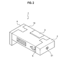
- Fig. 2 shows the hearing aid 1 in which the functional modules are assembled to the stereoscopic circuit board 10.
- the signal processing module 3 processes sounds collected by the microphone 21 so that they have frequency characteristics in response to the user's hearing acuity. Therefore, the signal processing module 3 is customized in order to satisfy the user's requirement.
- the signal processing module 3 has on its side surfaces a pair of semicircular recesses 3a which face with each other. Further, the signal processing module 3 has on its surfaces electrodes 15 to be connected to the stereoscopic circuit board 10.
- the signal processing module 3 may be provided with a noise canceller in order to cancel noises.
- the speaker module 4 includes a speaker (not shown), and outputs, as voices, the voice signals processed by the signal processing module 3.
- the speaker module 4 has a projection 4A to be assembled to the stereoscopic circuit board 10.
- the projection 4A has a pair of half semicircular recesses 4a on its opposite side surfaces. Further, the projection 4A has electrodes 15 on its surfaces. The electrodes 15 are in electric contact with the stereoscopic circuit board 10 when assembled.
- the power source 5 supplies power to the modules constituting the hearing aid 1, and may be a replaceable primary cell or a rechargeable secondary cell.
- the stereoscopic circuit board 10 is fabricated by the following processes: injection molding an insulating substrate 11 in a desired shape; forming thin films thereon; removing the thin films in accordance with a profile of patterns using laser beams; applying electrolytic copper plating to the patterns; applying soft etching to unnecessary parts of the thin films; and making circuits by electrically applying nickel and gold plating.
- Japanese Laid-open Patent Publication No. Hei 7-66533 for details of fabricating the stereoscopic circuit board.
- the stereoscopic circuit board 10 is formed with recesses 10A, 10B and 10C into which the projections 2A of the microphone module 2, the projection 3A of the signal processing module 3 and the projections 4A of the speaker module 4 are fitted.
- the recess 10A has on its inner surface a pair of semicircular projections 10A1 to be engaged with the semicircular recesses 2a of the microphone module 2.
- This structure enables the stereoscopic circuit board 10 to be engaged with the microphone module 2.
- the electrodes 15 on the inner surface of the recess 10A are in pressure contact with the electrodes 15 on the projection 2A of the microphone module 2.
- the recess 10B has on its inner surface a pair of semicircular projections 10B1 to be engaged with the semicircular recesses 3a of the signal processing module 3.
- This structure enables the stereoscopic circuit board 10 to be engaged with the signal processing module 3.
- the electrodes 15 on the inner surface of the recess 10B are in pressure contact with the electrodes 15 on the side surfaces of the signal processing module 3.
- the recess 10C has on its inner surface a pair of semicircular projections 10C1 to be engaged with the semicircular recesses 4a of the speaker module 4.
- This structure enables the stereoscopic circuit board 10 to be engaged with the speaker module 4.
- the electrodes 15 on the inner surface of the recess 10C are in pressure contact with the electrodes 15 on the projections 4A of the speaker module 4.
- the stereoscopic circuit board 10 has a recess 10D into which the power source 5 (e.g. a battery) is fitted. Further, the stereoscopic circuit board 10 has a plurality of through-holes (not shown) in order to make the electrodes 15 extend therein. This enables the modules assembled in the stereoscopic circuit board 10 to be electrically and reliably connected.
- the power source 5 e.g. a battery
- the stereoscopic circuit board 10 has a plurality of through-holes (not shown) in order to make the electrodes 15 extend therein. This enables the modules assembled in the stereoscopic circuit board 10 to be electrically and reliably connected.
- the various functional modules can be easily assembled on the stereoscopic circuit board 10, which is effective in improving the quality and reliability of the hearing aid 1. Further, the absence of lead wires reduces component assembling spaces and can downsize the hearing aid 1.
- the signal processing module 3 has to be customized in order to accomplish frequency characteristics in accordance with user's hearing acuity. Since the signal processing module 3 can be easily assembled on the stereoscopic circuit board 10 without using any lead wires, the hearing aid 1 can be shipped to the user after checking the user's hearing ability. This means that a shipping deadline can be extensively accelerated.
- the invention is applied to a radio receiver.
- the radio receiver (not shown) includes an antenna module which is made by modifying the microphone module 2 of the hearing aid 1 (shown in Fig. 1 and Fig. 2 ) in order to receive radio waves transmitted by an external source, and a tuner module by modifying the signal processing module 3 in order to receive radio waves having optional frequencies and demodulate the received radio waves.
- the various functional modules can be easily assembled on the stereoscopic circuit board 10, which is effective in improving the quality and reliability of the radio receiver. Further, the absence of lead wires reduces component assembling spaces and can downsize the radio receiver.
- the invention is applied to a playback unit.
- the playback unit (not shown) includes a loading module and a playback module.
- the loading module is made by modifying the microphone module 2 of the hearing aid 1 (shown in Fig. 1 and Fig. 2 ) while the playback module is made by modifying the signal processing module 3.
- the loading module has a slot for receiving a memory storing voice signals.
- the playback module reads out the voice signals from the memory, and demodulates the voice signals.
- the various functional modules can be easily assembled on the stereoscopic circuit board 10, which is effective in improving the quality and reliability of the playback unit. Further, the absence of lead wires reduces component assembling spaces and can downsize the playback unit.
- the invention is intended to overcome problems related to complicated assembling processes, improves the quality and reliability of appliances to which the invention is applied, and can accomplish downsizing.
Abstract
Description
- This invention relates to a voice output unit which amplifies voice signals and outputs voice sounds outside.
- As electronics devices are being extensively downsized, components constituting them are required to be assembled in a harmonized and packed manner and to save spaces. In order to meet such a requirement, more and more electronic devices become very difficult to be assembled on an existing flat printed circuit board like a glass epoxy printed circuit board. The Molded Interconnect Device (MID) technology has been proposed in order to overcome the foregoing problem. Specifically, the Microscopic Integrated Processing Technology (MITPTEC) has been proposed in order that micro fabricated electronic circuits can be three-dimensionally mounted on a molded circuit board. Refer to Japanese Patent Laid-open Publication
Hei 7-66533 - The Microscopic Integrated Processing Technology is applicable to fabricating appliances in which electric circuits, electric mechanical functional components and so on are assembled on a molded circuit board. Specifically, microscopic three-dimensional circuits can be fabricated by using lasers. Further, circuit patterns on printed circuit boards can be freely modified.
- Usually, the following appliances are put on or hooked on users' ears, and should be very small; a hearing aid which collects sounds from an external source, amplifies them, and output them to a user; a radio receiver which amplifies voice signals superimposed on transmitted radio waves and outputs them as voice sounds; a playback unit which reads stored voice signals from a memory and outputs them as voice sounds. The foregoing appliances are strongly demanded to be small by users.
- There is a problem that it is very difficult to downsize such appliances when flat printed circuit boards are used. Further, functional components have to be connected using lead wires, which complicates an assembling process. Still further, incorrect wiring or disconnections may lead to problems which will result in reduced quality or reliability of appliances.
- The present invention has been contemplated in order to provide a voice output unit which can overcome problems of the related art, and can simplify an assembling process, improves the quality and reliability, and is small as possible.
- According to the invention, there is provided a voice output unit which includes: a power source supplying power to the voice output unit; a signal processing module which processes voice signals received from an external source as predetermined; an amplifier module which amplifies the voice signals processed by the signal processing module; an output module transmitting the amplified voice signals as voices; and a stereoscopic circuit board on which the power source, signal processing module, amplifier module and output module are assembled, and includes electrodes which are in electric contact with electrodes of the foregoing components.
- The voice output unit further includes a sound collector which collects voice signals from the external source. The signal processing module processes the voice signals as predetermined.
- The voice output unit includes a radio receiver which receives radio waves transmitted from the external source. The signal processing module processes voice signals which are superimposed on the received radio waves.
- Further, the voice output unit includes a loading module to which a memory storing voice signals is attached. The signal processing module reads the voice signals from the memory, and processes the voice signals as predetermined.
-
- [
Fig. 1] Fig. 1 is an exploded perspective view of a hearing aid according to a first embodiment of the invention. - [
Fig. 2] Fig. 2 is a perspective view of the hearing aid in an assembled state in the first embodiment. - The invention will be described with reference to embodiments shown in the drawings.
- In a first embodiment, the invention is applied to a
hearing aid 1. Referring toFig. 1 , thehearing aid 1 includes amicrophone module 2, asignal processing module 3, aspeaker module 4, apower source 5, and astereoscopic circuit board 10. Specifically,Fig. 1 shows a state in which the functional modules are not assembled to thestereoscopic circuit board 10.Fig. 2 shows thehearing aid 1 in which the functional modules are assembled to thestereoscopic circuit board 10. - As shown in
Fig. 1 , themicrophone module 2 includes amicrophone 21 collecting sounds from an external source, and has a projection 2A to be engaged with thestereoscopic circuit board 10. The projection 2A has twosemicircular recesses 2a on its opposite side surfaces. Further, the projection 2A haselectrodes 15 on its surfaces. Theelectrodes 15 are in electrical contact with thestereoscopic circuit board 10 when assembled. - The
signal processing module 3 processes sounds collected by themicrophone 21 so that they have frequency characteristics in response to the user's hearing acuity. Therefore, thesignal processing module 3 is customized in order to satisfy the user's requirement. Thesignal processing module 3 has on its side surfaces a pair ofsemicircular recesses 3a which face with each other. Further, thesignal processing module 3 has on itssurfaces electrodes 15 to be connected to thestereoscopic circuit board 10. - The
signal processing module 3 may be provided with a noise canceller in order to cancel noises. - The
speaker module 4 includes a speaker (not shown), and outputs, as voices, the voice signals processed by thesignal processing module 3. Thespeaker module 4 has aprojection 4A to be assembled to thestereoscopic circuit board 10. Theprojection 4A has a pair of halfsemicircular recesses 4a on its opposite side surfaces. Further, theprojection 4A haselectrodes 15 on its surfaces. Theelectrodes 15 are in electric contact with thestereoscopic circuit board 10 when assembled. - The
power source 5 supplies power to the modules constituting thehearing aid 1, and may be a replaceable primary cell or a rechargeable secondary cell. - The
stereoscopic circuit board 10 is fabricated by the following processes: injection molding an insulating substrate 11 in a desired shape; forming thin films thereon; removing the thin films in accordance with a profile of patterns using laser beams; applying electrolytic copper plating to the patterns; applying soft etching to unnecessary parts of the thin films; and making circuits by electrically applying nickel and gold plating. Refer to Japanese Laid-open Patent Publication No.Hei 7-66533 - After the foregoing fabrication processes, the
stereoscopic circuit board 10 is formed withrecesses microphone module 2, the projection 3A of thesignal processing module 3 and theprojections 4A of thespeaker module 4 are fitted. - The
recess 10A has on its inner surface a pair of semicircular projections 10A1 to be engaged with thesemicircular recesses 2a of themicrophone module 2. This structure enables thestereoscopic circuit board 10 to be engaged with themicrophone module 2. Specifically, theelectrodes 15 on the inner surface of therecess 10A are in pressure contact with theelectrodes 15 on the projection 2A of themicrophone module 2. - The
recess 10B has on its inner surface a pair of semicircular projections 10B1 to be engaged with thesemicircular recesses 3a of thesignal processing module 3. This structure enables thestereoscopic circuit board 10 to be engaged with thesignal processing module 3. Specifically, theelectrodes 15 on the inner surface of therecess 10B are in pressure contact with theelectrodes 15 on the side surfaces of thesignal processing module 3. - The
recess 10C has on its inner surface a pair of semicircular projections 10C1 to be engaged with thesemicircular recesses 4a of thespeaker module 4. This structure enables thestereoscopic circuit board 10 to be engaged with thespeaker module 4. Specifically, theelectrodes 15 on the inner surface of therecess 10C are in pressure contact with theelectrodes 15 on theprojections 4A of thespeaker module 4. - The
stereoscopic circuit board 10 has arecess 10D into which the power source 5 (e.g. a battery) is fitted. Further, thestereoscopic circuit board 10 has a plurality of through-holes (not shown) in order to make theelectrodes 15 extend therein. This enables the modules assembled in thestereoscopic circuit board 10 to be electrically and reliably connected. - In the
hearing aid 1, the various functional modules can be easily assembled on thestereoscopic circuit board 10, which is effective in improving the quality and reliability of thehearing aid 1. Further, the absence of lead wires reduces component assembling spaces and can downsize thehearing aid 1. - The
signal processing module 3 has to be customized in order to accomplish frequency characteristics in accordance with user's hearing acuity. Since thesignal processing module 3 can be easily assembled on thestereoscopic circuit board 10 without using any lead wires, thehearing aid 1 can be shipped to the user after checking the user's hearing ability. This means that a shipping deadline can be extensively accelerated. - In a second embodiment, the invention is applied to a radio receiver. The radio receiver (not shown) includes an antenna module which is made by modifying the
microphone module 2 of the hearing aid 1 (shown inFig. 1 andFig. 2 ) in order to receive radio waves transmitted by an external source, and a tuner module by modifying thesignal processing module 3 in order to receive radio waves having optional frequencies and demodulate the received radio waves. - Needless to say, it is possible to reduce the number of components by making an antenna circuit directly on the
stereoscopic circuit board 10, and to improve the assembling process. - In the radio receiver of the second embodiment, the various functional modules can be easily assembled on the
stereoscopic circuit board 10, which is effective in improving the quality and reliability of the radio receiver. Further, the absence of lead wires reduces component assembling spaces and can downsize the radio receiver. - In a third embodiment, the invention is applied to a playback unit. The playback unit (not shown) includes a loading module and a playback module. The loading module is made by modifying the
microphone module 2 of the hearing aid 1 (shown inFig. 1 andFig. 2 ) while the playback module is made by modifying thesignal processing module 3. The loading module has a slot for receiving a memory storing voice signals. The playback module reads out the voice signals from the memory, and demodulates the voice signals. - In the playback unit of the third embodiment, the various functional modules can be easily assembled on the
stereoscopic circuit board 10, which is effective in improving the quality and reliability of the playback unit. Further, the absence of lead wires reduces component assembling spaces and can downsize the playback unit. - While we have shown and described some embodiments in accordance with our invention, it should be understood that disclosed embodiments are susceptible to changes and modifications without departing from the scope of the invention. Therefore, we do not intend to be bound by the details shown and described herein but intend to cover all such changes and modifications that fall within the ambit of the appended claims.
- The invention is intended to overcome problems related to complicated assembling processes, improves the quality and reliability of appliances to which the invention is applied, and can accomplish downsizing.
Claims (4)
- A voice output unit comprising:a power source supplying power to the voice output unit;a signal processing module which processes voice signals received from an external source as predetermined;an amplifier module which amplifies the voice signals processed by the signal processing module;an output module transmitting the amplified voice signals as voices; anda stereoscopic circuit board on which the power source, signal processing module, amplifier module and output module are assembled, and includes electrodes which are in electric contact with electrodes of the foregoing components.
- The voice output unit defined in claim 1 further comprising a sound collector which collects voice signals from the external source, wherein the signal processing module processes the collected voice signals as predetermined.
- The voice output unit defined in claim 1 further comprising a radio receiver which receives radio waves transmitted from the external source, wherein the signal processing module processes voice signals which are superimposed on the received radio waves.
- The voice output unit defined in claim 1 further comprising a loading module to which a memory storing voice signals is attached, wherein the signal processing module reads the voice signals from the memory, and processes the voice signals as predetermined.
Applications Claiming Priority (2)
| Application Number | Priority Date | Filing Date | Title |
|---|---|---|---|
| JP2006269767A JP2008091554A (en) | 2006-09-29 | 2006-09-29 | Speech output equipment |
| PCT/JP2007/068125 WO2008041479A1 (en) | 2006-09-29 | 2007-09-19 | Audio output device |
Publications (2)
| Publication Number | Publication Date |
|---|---|
| EP2063694A1 true EP2063694A1 (en) | 2009-05-27 |
| EP2063694A4 EP2063694A4 (en) | 2010-09-22 |
Family
ID=39268341
Family Applications (1)
| Application Number | Title | Priority Date | Filing Date |
|---|---|---|---|
| EP07807512A Withdrawn EP2063694A4 (en) | 2006-09-29 | 2007-09-19 | Audio output device |
Country Status (6)
| Country | Link |
|---|---|
| US (1) | US8150071B2 (en) |
| EP (1) | EP2063694A4 (en) |
| JP (1) | JP2008091554A (en) |
| KR (1) | KR101133796B1 (en) |
| CN (1) | CN101507376B (en) |
| WO (1) | WO2008041479A1 (en) |
Cited By (10)
| Publication number | Priority date | Publication date | Assignee | Title |
|---|---|---|---|---|
| EP1998594A3 (en) * | 2007-05-30 | 2010-04-28 | Siemens Medical Instruments Pte. Ltd. | Hearing device element support with battery recess |
| WO2014090419A1 (en) * | 2012-12-12 | 2014-06-19 | Siemens Medical Instruments Pte. Ltd. | Modular antenna for hearing devices |
| EP2874476A1 (en) * | 2013-11-14 | 2015-05-20 | Siemens Aktiengesellschaft | Printed circuit base board, module circuit board and circuit board assembly with a base board and a module circuit board |
| US20150146899A1 (en) * | 2013-11-27 | 2015-05-28 | Starkey Laboratories, Inc. | Solderless hearing assistance device assembly and method |
| US20150230035A1 (en) * | 2013-11-27 | 2015-08-13 | Starkey Laboratories, Inc. | Solderless module connector for a hearing assistance device assembly |
| EP2910034B1 (en) | 2012-10-22 | 2016-10-19 | Sivantos Pte. Ltd. | Routing building block for complex mid structures in hearing instruments |
| EP3086576A1 (en) * | 2015-04-22 | 2016-10-26 | David Prchal | Solderless module connector for a hearing assistance device assembly |
| CN106304718A (en) * | 2016-07-10 | 2017-01-04 | 安徽省挺辉钢管有限公司 | There is the signal cabinet connecting plate of insulation function |
| US9980062B2 (en) | 2012-12-12 | 2018-05-22 | Sivantos Pte. Ltd. | Hearing aid and method for producing a hearing aid |
| WO2020153937A1 (en) * | 2019-01-22 | 2020-07-30 | Siemens Aktiengesellschaft | Integrated no-solder snap-fit electronic component bays for non-traditional pcbs and am structures |
Families Citing this family (6)
| Publication number | Priority date | Publication date | Assignee | Title |
|---|---|---|---|---|
| CN104363534B (en) * | 2014-10-20 | 2019-03-29 | 佳禾智能科技股份有限公司 | A kind of Novel earphone line traffic control and preparation method thereof |
| JP6358132B2 (en) * | 2015-03-03 | 2018-07-18 | オムロン株式会社 | 3D circuit structure |
| US11206499B2 (en) | 2016-08-18 | 2021-12-21 | Qualcomm Incorporated | Hearable device comprising integrated device and wireless functionality |
| EP3932151A4 (en) * | 2019-03-29 | 2022-04-06 | Nano-Dimension Technologies, Ltd. | Additively manufactured electronic (ame) circuits having side-mounted components |
| CN110996512B (en) * | 2019-12-30 | 2022-03-04 | 展讯通信(上海)有限公司 | Printed circuit board, manufacturing method thereof and terminal |
| JP2022160334A (en) * | 2021-04-06 | 2022-10-19 | キヤノン株式会社 | Base member |
Citations (3)
| Publication number | Priority date | Publication date | Assignee | Title |
|---|---|---|---|---|
| GB357171A (en) * | 1930-06-10 | 1931-09-10 | Paragon Rubber Mfg Company Ltd | Improvements in and relating to wireless and like electrical apparatus |
| WO2001043497A1 (en) * | 1999-12-10 | 2001-06-14 | Sonic Innovations, Inc. | Flexible circuit board assembly for a hearing aid |
| US6324291B1 (en) * | 1998-06-10 | 2001-11-27 | Siemens Audiologische Technik Gmbh | Head-worn hearing aid with suppression of oscillations affecting the amplifier and transmission stage |
Family Cites Families (12)
| Publication number | Priority date | Publication date | Assignee | Title |
|---|---|---|---|---|
| JPH05335995A (en) * | 1992-06-02 | 1993-12-17 | Fujitsu Ltd | Portable communication equipment |
| CN2165579Y (en) | 1993-07-22 | 1994-05-18 | 朱一兵 | Wireless electronic voice traveling guide device |
| JP3153682B2 (en) | 1993-08-26 | 2001-04-09 | 松下電工株式会社 | Circuit board manufacturing method |
| US20010040973A1 (en) * | 1997-03-12 | 2001-11-15 | Sarnoff Corporation | Hearing aid with tinted components |
| JP2001068867A (en) * | 1999-08-30 | 2001-03-16 | Hitachi Kokusai Electric Inc | Optical relay structure |
| JP2002076649A (en) * | 2000-08-30 | 2002-03-15 | Pentel Corp | Positioning mechanism of directional electronic apparatus |
| CN2591913Y (en) | 2002-12-16 | 2003-12-10 | 四川微迪数字技术有限公司 | Full digital hearing-aid |
| CN1681278A (en) * | 2004-04-07 | 2005-10-12 | 明基电通股份有限公司 | Mobile earphone with deaf-aid volume adjusting function and method thereof |
| CN1619610A (en) | 2004-11-18 | 2005-05-25 | 李振刚 | Automatic speech sound eeplaining system |
| CN2847765Y (en) * | 2004-11-22 | 2006-12-13 | 丁晋辰 | High power ear back type hearing aid |
| JP4997250B2 (en) * | 2005-12-19 | 2012-08-08 | エヌエックスピー ビー ヴィ | Wireless receiver, wireless transmitter and hearing aid |
| JP4103920B2 (en) * | 2006-07-31 | 2008-06-18 | 松下電工株式会社 | 3D circuit board and fingerprint sensor device |
-
2006
- 2006-09-29 JP JP2006269767A patent/JP2008091554A/en not_active Withdrawn
-
2007
- 2007-09-19 CN CN2007800309009A patent/CN101507376B/en not_active Expired - Fee Related
- 2007-09-19 WO PCT/JP2007/068125 patent/WO2008041479A1/en active Application Filing
- 2007-09-19 US US12/376,602 patent/US8150071B2/en active Active
- 2007-09-19 KR KR1020097003354A patent/KR101133796B1/en active IP Right Grant
- 2007-09-19 EP EP07807512A patent/EP2063694A4/en not_active Withdrawn
Patent Citations (3)
| Publication number | Priority date | Publication date | Assignee | Title |
|---|---|---|---|---|
| GB357171A (en) * | 1930-06-10 | 1931-09-10 | Paragon Rubber Mfg Company Ltd | Improvements in and relating to wireless and like electrical apparatus |
| US6324291B1 (en) * | 1998-06-10 | 2001-11-27 | Siemens Audiologische Technik Gmbh | Head-worn hearing aid with suppression of oscillations affecting the amplifier and transmission stage |
| WO2001043497A1 (en) * | 1999-12-10 | 2001-06-14 | Sonic Innovations, Inc. | Flexible circuit board assembly for a hearing aid |
Non-Patent Citations (1)
| Title |
|---|
| See also references of WO2008041479A1 * |
Cited By (14)
| Publication number | Priority date | Publication date | Assignee | Title |
|---|---|---|---|---|
| EP1998594A3 (en) * | 2007-05-30 | 2010-04-28 | Siemens Medical Instruments Pte. Ltd. | Hearing device element support with battery recess |
| EP2910034B1 (en) | 2012-10-22 | 2016-10-19 | Sivantos Pte. Ltd. | Routing building block for complex mid structures in hearing instruments |
| US9571944B2 (en) | 2012-12-12 | 2017-02-14 | Sivantos Pte. Ltd. | Hearing aid and method for producing a hearing aid |
| WO2014090419A1 (en) * | 2012-12-12 | 2014-06-19 | Siemens Medical Instruments Pte. Ltd. | Modular antenna for hearing devices |
| US9980062B2 (en) | 2012-12-12 | 2018-05-22 | Sivantos Pte. Ltd. | Hearing aid and method for producing a hearing aid |
| EP2874476A1 (en) * | 2013-11-14 | 2015-05-20 | Siemens Aktiengesellschaft | Printed circuit base board, module circuit board and circuit board assembly with a base board and a module circuit board |
| US20150146899A1 (en) * | 2013-11-27 | 2015-05-28 | Starkey Laboratories, Inc. | Solderless hearing assistance device assembly and method |
| EP2879407A1 (en) * | 2013-11-27 | 2015-06-03 | Starkey Laboratories, Inc. | Solderless hearing assistance device assembly and method |
| US20150230035A1 (en) * | 2013-11-27 | 2015-08-13 | Starkey Laboratories, Inc. | Solderless module connector for a hearing assistance device assembly |
| US9906879B2 (en) * | 2013-11-27 | 2018-02-27 | Starkey Laboratories, Inc. | Solderless module connector for a hearing assistance device assembly |
| US9913052B2 (en) | 2013-11-27 | 2018-03-06 | Starkey Laboratories, Inc. | Solderless hearing assistance device assembly and method |
| EP3086576A1 (en) * | 2015-04-22 | 2016-10-26 | David Prchal | Solderless module connector for a hearing assistance device assembly |
| CN106304718A (en) * | 2016-07-10 | 2017-01-04 | 安徽省挺辉钢管有限公司 | There is the signal cabinet connecting plate of insulation function |
| WO2020153937A1 (en) * | 2019-01-22 | 2020-07-30 | Siemens Aktiengesellschaft | Integrated no-solder snap-fit electronic component bays for non-traditional pcbs and am structures |
Also Published As
| Publication number | Publication date |
|---|---|
| US20100183169A1 (en) | 2010-07-22 |
| EP2063694A4 (en) | 2010-09-22 |
| CN101507376A (en) | 2009-08-12 |
| WO2008041479A1 (en) | 2008-04-10 |
| JP2008091554A (en) | 2008-04-17 |
| KR20090031632A (en) | 2009-03-26 |
| KR101133796B1 (en) | 2012-04-05 |
| US8150071B2 (en) | 2012-04-03 |
| CN101507376B (en) | 2012-03-28 |
Similar Documents
| Publication | Publication Date | Title |
|---|---|---|
| US8150071B2 (en) | Voice output unit | |
| US9264826B2 (en) | Three dimensional substrate for hearing assistance devices | |
| US8300870B2 (en) | Variable directional microphone assembly and method of making the microphone assembly | |
| US9769562B2 (en) | Microphone system with non-orthogonally mounted microphone die | |
| US10142747B2 (en) | Three dimensional substrate for hearing assistance devices | |
| EP2879407B1 (en) | Solderless hearing assistance device assembly and method | |
| EP1532842B1 (en) | Hearing aid or similar audio device and method for producing a hearing aid | |
| US11445309B2 (en) | Cable for a hearing device | |
| US20110188694A1 (en) | variable directional microphone assembly and method of making the microphone assembly | |
| KR20060096311A (en) | Electro-acoustic transducer with holder | |
| US20080298617A1 (en) | Hearing aid component holder with battery cavity | |
| EP2324643B1 (en) | Hearing aid faceplate arrangement | |
| JP2003299175A (en) | Electroacoustic transducer | |
| JPWO2019197568A5 (en) | ||
| US20180317032A1 (en) | Method for producing a supporting frame of a hearing aid, supporting frame and hearing aid |
Legal Events
| Date | Code | Title | Description |
|---|---|---|---|
| PUAI | Public reference made under article 153(3) epc to a published international application that has entered the european phase |
Free format text: ORIGINAL CODE: 0009012 |
|
| 17P | Request for examination filed |
Effective date: 20090209 |
|
| AK | Designated contracting states |
Kind code of ref document: A1 Designated state(s): AT BE BG CH CY CZ DE DK EE ES FI FR GB GR HU IE IS IT LI LT LU LV MC MT NL PL PT RO SE SI SK TR |
|
| AX | Request for extension of the european patent |
Extension state: AL BA HR MK RS |
|
| A4 | Supplementary search report drawn up and despatched |
Effective date: 20100823 |
|
| DAX | Request for extension of the european patent (deleted) | ||
| RBV | Designated contracting states (corrected) |
Designated state(s): DE FR GB |
|
| STAA | Information on the status of an ep patent application or granted ep patent |
Free format text: STATUS: THE APPLICATION IS DEEMED TO BE WITHDRAWN |
|
| 18D | Application deemed to be withdrawn |
Effective date: 20110322 |