EP2063622A1 - Identifying callers in telecommunications networks - Google Patents
Identifying callers in telecommunications networks Download PDFInfo
- Publication number
- EP2063622A1 EP2063622A1 EP08104797A EP08104797A EP2063622A1 EP 2063622 A1 EP2063622 A1 EP 2063622A1 EP 08104797 A EP08104797 A EP 08104797A EP 08104797 A EP08104797 A EP 08104797A EP 2063622 A1 EP2063622 A1 EP 2063622A1
- Authority
- EP
- European Patent Office
- Prior art keywords
- terminal
- speech data
- uplink
- receiving
- signal
- Prior art date
- Legal status (The legal status is an assumption and is not a legal conclusion. Google has not performed a legal analysis and makes no representation as to the accuracy of the status listed.)
- Granted
Links
Images

Classifications
-
- H—ELECTRICITY
- H04—ELECTRIC COMMUNICATION TECHNIQUE
- H04M—TELEPHONIC COMMUNICATION
- H04M3/00—Automatic or semi-automatic exchanges
- H04M3/42—Systems providing special services or facilities to subscribers
- H04M3/56—Arrangements for connecting several subscribers to a common circuit, i.e. affording conference facilities
- H04M3/561—Arrangements for connecting several subscribers to a common circuit, i.e. affording conference facilities by multiplexing
-
- H—ELECTRICITY
- H04—ELECTRIC COMMUNICATION TECHNIQUE
- H04L—TRANSMISSION OF DIGITAL INFORMATION, e.g. TELEGRAPHIC COMMUNICATION
- H04L12/00—Data switching networks
- H04L12/02—Details
- H04L12/16—Arrangements for providing special services to substations
- H04L12/18—Arrangements for providing special services to substations for broadcast or conference, e.g. multicast
- H04L12/1813—Arrangements for providing special services to substations for broadcast or conference, e.g. multicast for computer conferences, e.g. chat rooms
- H04L12/1822—Conducting the conference, e.g. admission, detection, selection or grouping of participants, correlating users to one or more conference sessions, prioritising transmission
-
- H—ELECTRICITY
- H04—ELECTRIC COMMUNICATION TECHNIQUE
- H04M—TELEPHONIC COMMUNICATION
- H04M3/00—Automatic or semi-automatic exchanges
- H04M3/42—Systems providing special services or facilities to subscribers
- H04M3/42025—Calling or Called party identification service
- H04M3/42034—Calling party identification service
- H04M3/42042—Notifying the called party of information on the calling party
-
- H—ELECTRICITY
- H04—ELECTRIC COMMUNICATION TECHNIQUE
- H04M—TELEPHONIC COMMUNICATION
- H04M3/00—Automatic or semi-automatic exchanges
- H04M3/42—Systems providing special services or facilities to subscribers
- H04M3/56—Arrangements for connecting several subscribers to a common circuit, i.e. affording conference facilities
- H04M3/568—Arrangements for connecting several subscribers to a common circuit, i.e. affording conference facilities audio processing specific to telephonic conferencing, e.g. spatial distribution, mixing of participants
-
- H—ELECTRICITY
- H04—ELECTRIC COMMUNICATION TECHNIQUE
- H04W—WIRELESS COMMUNICATION NETWORKS
- H04W4/00—Services specially adapted for wireless communication networks; Facilities therefor
- H04W4/18—Information format or content conversion, e.g. adaptation by the network of the transmitted or received information for the purpose of wireless delivery to users or terminals
-
- H—ELECTRICITY
- H04—ELECTRIC COMMUNICATION TECHNIQUE
- H04L—TRANSMISSION OF DIGITAL INFORMATION, e.g. TELEGRAPHIC COMMUNICATION
- H04L63/00—Network architectures or network communication protocols for network security
- H04L63/12—Applying verification of the received information
- H04L63/126—Applying verification of the received information the source of the received data
-
- H—ELECTRICITY
- H04—ELECTRIC COMMUNICATION TECHNIQUE
- H04W—WIRELESS COMMUNICATION NETWORKS
- H04W4/00—Services specially adapted for wireless communication networks; Facilities therefor
- H04W4/06—Selective distribution of broadcast services, e.g. multimedia broadcast multicast service [MBMS]; Services to user groups; One-way selective calling services
Definitions
- the invention relates to calls in telecommunication networks and more particularly, but not exclusively, to conference calls in telecommunication systems having a plurality of transmitter/receiver units, where compression and/or decompression of data relating to the call is performed.
- conferencing bridge In a conference call several users will dial into a conferencing bridge system (even if this is masked and they do not think that they are). This bridge will merge the incoming speech data from all lines into a single downlink and push this back to the remaining users on the call. Thus, conventionally speech data overlaps and cannot be separated once at the receiving terminal. Further, the speech data within each uplink will be bandwidth limited and compressed (using standard processes as would be performed with any GSM/3G call).
- Conference calling in such telecommunication systems allows multiple callers in different locations to interact in a single voice call.
- a problem with such conference calls is differentiating between participants using a single mono audio output of the type that is normal with mobile handsets. This is exacerbated by network bandwidth limitations in such conference calls as well as signal compression that results in many of the subtle clues used by a person to recognise another person's voice being lost.
- human voice is bandwidth limited to 4 kHz and all incoming lines are overlapped to create a single downlink to a single speaker. It is therefore difficult to differentiate between users, or decide when a new user begins to speak, as well as knowing how many people are involved in the call and remembering their names.
- GB 2416955 discloses an arrangement to reduce bandwidth required to relay signals simultaneously from all participants in the conference call.
- a method of performing a call in a telecommunication system having a plurality of transmitter/receiver units registered with a telecommunications network including: receiving in the network an uplink signal representing detected sound from an originating unit, generating a downlink signal by encoding said uplink signal such that data indicative of a tag corresponding to the originating unit is embedded in a payload of said downlink signal, which payload conveys the detected sound, receiving the downlink signal, and extracting said embedded tag from the downlink signal in order to identify the originating unit corresponding to the tag.
- the example embodiment to be described makes it possible to "tag" the users within a call in a way that can cross the network without degradation and to then spatialise their voice using a software client on the handset. This would be easy apart from the fact that all voices are merged into one. So a method of tagging voices, and extracting them after merging and compression is to be used.
- embedding a watermarked tag e.g. a basic binary number, or other identifier into the speech data of incoming calls can allow the users to be distinguished.
- Embedding a tag into the speech data of uplinked conference calls by use of compression resistant watermarking technology can allow each individual incoming line to the conference bridge to be "tagged" and assigned to a particular user.
- each incoming line When arriving at the conference bridge, each incoming line is merged into one overlapping downlink and pushed back to all other users on the call in the embodiment. This would conventionally impose server difficulties in allowing individual voices to be extracted and for the positioning process.
- individuals can be identified and extracted real time, allowing the receiving terminal to manipulate individual lines, for example by 3D spatialising them.
- the watermark may be added either in the uplinking terminal using a client or in the network before merging (with the bridge) and at any point of compression (both within the terminal and subsequent PCM conversion within the TRAU in the network) as the watermark should be impervious to this.
- the watermark is added before the merge.
- the compression is preferably that used within a standard GSM/3G call.
- the tag is embedded in the payload by watermarking the payload.
- watermarking For example, DC watermarking, phase encoding watermarking, spread spectrum watermarking or echo watermarking may be used.
- a method of performing a call in a telecommunications network including receiving in the uplink, speech data from a first terminal registered with the telecommunications network; receiving in the uplink, speech data from a second terminal registered with the telecommunications network; adding a watermark to the received speech data from the first terminal to generate watermarked speech data of the first terminal; adding a watermark to the received speech data from the second terminal to generate watermarked speech data of the second terminal; generating a downlink signal for a receiving terminal registered with the network including both the watermarked speech data of the first terminal and the watermarked speech data of the second terminal; receiving the downlink signal at the receiving terminal; identifying the watermarked speech data of the first terminal; identifying the watermarked speech data of the second terminal.
- the method may further include producing at the receiving terminal a spatially resolved audio signal in which the uplink speech data from the first terminal and the uplink speech data from the second terminal are reproduced at distinct locations in a two-dimensional or three-dimensional space.
- the downlink is pushed to all terminals within the call.
- the spatially resolved audio signal may be generated by stereo panning or by 2D or 3D virtualised audio for example.
- the uplink and/or downlink data may be transmitted in the circuit switched domain or the packet switched domain.
- the two separate speech lines are extracted and then spatially resolved.
- the caller may be identified in ways other than producing a spatially resolved audio signal. If the voice data have been tagged and then extracted using a client application on the terminal, the terminal is then aware of how many people are within the call and can spatially resolve them. However, a terminal could also draw a graphical depiction of a room and show a depiction of the users, could list their names, or show their picture when they are talking etc. This may require either further information to be passed via the watermark, or to be tied into other data such as the phone book.
- the present invention also relates to apparatus for performing a call in a telecommunications network as defined in the independent claims.
- the apparatus may include an originating unit and/or a receiving unit, in addition to means for receiving an uplink signal and means for generating a downlink signal.
- the received uplink signals are each watermarked.
- a conference bridge then compresses the watermarked uplink signals and transmits them on the downlink channel to the receiving unit.
- the conference bridge and/or network will bandwidth limit, compress, and merge all uplinks into one downlink that is then pushed to all other members of the call.
- speech data from individual terminals sent in the uplink signal can be extracted in real time from the data received by the receiving terminal.
- the receiving terminal decompresses the downlink channel and then extracts the watermarks in order to identify from which terminal the speech data associated with that watermark was transmitted.
- a positioning algorithm in the receiving terminal can then place speech data from each originating terminal at a particular position in a 2D or 3D space around the user.
- the call participants can be indicated in other ways - e.g. by listing names or drawing a room.
- 3D audio spatialisation is one example of an excellent way of improving audio conference intelligibility, especially for mobile telecommunications networks where bandwidth is restricted and sound quality limited. It will generally only be feasible to implement such a service if the tagging of voice data from particular originating units does not consume excessive bandwidth, and also avoids undue implementation cost to either terminal, network or back-end platforms.
- the tags are such that they make it through the bandwidth limiting and compression.
- the embodiment allows 3D audio spatialisation in an audio conference using client-based spatialisation without an excessive increase in service bit rate and without noticeably affecting the quality of the speech reproduction.
- the network is a GSM network including a plurality of mobile transmitter/receiver units of which five 10, 11, 12, 13, 14 are shown in Figure 1 .
- the network includes a mobile switching centre (MSC) 15, a base station controller (BSC) 16 and a plurality of base transceiver stations (BTS), one of which is shown at 17.
- MSC mobile switching centre
- BSC base station controller
- BTS base transceiver stations
- the MSC 15 includes a conference bridge 18 that permits the plurality of mobile units 10, 11, 12, 13, 14 to communicate in a single voice (conference) call.
- Each mobile unit 10, 11, 12, 13, 14 transmits to the MSC 15 via a BTS and BSC in the uplink, a signal that includes a voice component of the user of that mobile.
- a BTS and BSC in the uplink
- the conference bridge 18 allows the voice components received in the uplink from each mobile unit 10,11,12,13,14 to be combined and transmitted in the downlink as a single CS channel.
- Speech is encoded by a multi-channel variable bitrate audio/speech coder 30 in the conference bridge 18.
- a coder 30 produces an optimal bitstream for conveying the speech component to a receiving unit 10, 11, 12, 13, 14 in the downlink channel.
- the coded signals representing speech are then fed via a BSC 16 and a BTS 17 to a receiving unit 14.
- the speech data from each mobile unit 10,11,12,13 is conveyed in a respective sub-channel of the downlink channel 20.
- Each sub-channel includes a tagging identifier that identifies the transmitting unit.
- one sub-channel will be carrying the speech of the current speaker and "silent" sub-channels for each of the other speakers (usually only one participant in the conference call speaks at a time).
- the coder 30 compresses the speech data from the mobile units 10,11,12,13 using a suitable compression algorithm.
- GSM compression may be used, or alternatively, or additionally, MP3 or WMA compression may be used, for example.
- the downlink channel is received and decompressed.
- the sub-channels and the respective tags associated therewith are then extracted from the received data.
- the sub-channels are passed to a spatial processor 21.
- the spatial processor 21 uses the tagging identifier and the coded speech signal to generate a analogue spatially resolved audio signal characteristic of the transmitter unit 10, 11, 12, 13 from which the signal emanates. If the receiving unit 14 has stereo loud speakers 26 then the spatial orientation of the signals will be mainly located in front of the person using the receiving unit 14 as seen in Figure 1 , assuming the unit is held in front of the person. Better spatial separation in 3D around the person (that is, in a 3D space around the person) may be obtained using, for example, stereo headphones.
- Such spatial processors 21 are known and will not be described in further detail.
- the analogue spatial audio signal produced at the receiving unit 14 may be a 3-D signal lying in an imaginary sphere around the receiving person. Alternatively, this may be a 2-D signal lying in an imaginary circle around the receiving person. It has been found that, in general 2-D signals in front of the receiving person are the most easily differentiated since the human body is best able to distinguish sounds over the front hemisphere of the body. The use of a 2-D or 3-D signal allows the user to distinguish more easily between participants and provides a more natural listening environment so reducing listening fatigue. It would also allow louder speakers to be moved further away and to move softer speakers closer. It gives the potential for a large number of conference participants due to the extended sound field and, since no background noise is received, increases the illegibility.
- the tagging identifiers each comprise an embedded watermarked tag in the speech data of incoming calls which allows the users to be distinguished.
- the tags are added to each incoming uplink channel by watermarking processors 32.
- the watermarking is preferably (though not necessarily) performed prior to compression by the coder 30.
- the watermarking performed by the watermarking processors 32 is resistant to the compression process performed by the coder 30, and to the decompression process performed by the receiving mobile unit 14. That is, the watermark tags inserted by the watermarking processors 32 are recognisable and intelligible by the mobile unit 14 after compression and decompression.
- the tag may be a basic binary number.
- FIG. 2 shows a time frame in accordance with this embodiment of the invention transmitted in the downlink channel to the receiving mobile unit 14.
- the time frame 34 comprises a header 36, a footer 38 and an information part (payload) 40.
- the information part 40 comprises information representing speech data from any of mobile units 10,11,12 and 13 that are participating in the conference call.
- information part 42 may comprise speech data from the mobile unit 10. Embedded within that speech data is a watermark tag representing the identity of the mobile unit 10.
- Embedding a basic binary number into the speech data itself by use of compression resistant watermarking technology provides an advantageous mechanism for each individual incoming uplink channel to the conference bridge 18 to be "tagged" and assigned to a particular user.
- each incoming line from the mobile units 10,11,12,13 is merged into one overlapping downlink and pushed back to mobile unit 14 (and to all users on the conference call).
- individuals can be identified and extracted real time allowing the positioning algorithm to take each individual and place them in 3D space around the user.
- the tagging information is hidden within the audio data in a format that is inaudible to a listener (i.e. outside the range of human perception), but can be detected and decoded by the receiving mobile unit.
- This hidden information, or watermark could be used to communicate not only participant tags, but also identity information and other meta data.
- the DC watermarking scheme hides watermark data in lower frequency components of the audio signal, which are below the perceptual threshold of the human auditory system.
- compression algorithms that are based on removing these inaudible parts of audio signals would remove all trace of the watermark.
- This DC watermarking scheme has some major limitations with regards to robustness and data density.
- the robustness of the scheme can be increased somewhat by utilising longer audio files, by inserting the watermark signal multiple times, which will aid in extraction, and also in error correction if the signal is manipulated.
- the highest rate and most versatile and reliable watermarking scheme may comprise a combination of all of the above, allowing the software to capitalise on the strengths of each technique when processing the unmarked audio.
- This watermarking technique exploits the human auditory system's lack of sensitivity to absolute phase changes by encoding the watermark data in an artificial phase signal.
- Phase encoding works by breaking the audio signal into frames, and performing spectral analysis on each frame. Once the spectrum has been computed, the magnitude and phase of consecutive frames are compared, and an artificial phase signal is created to transmit data. The artificial phase is modulated in with the phase from each frame, and the new phase frames are combined to form the watermarked signal.
- the modified phase frames can also be smoothed to limit the amount of distortion present in the marked signal, but in minimising distortion, the data rate of the watermark is constrained respectively.
- phase encoding watermarking technique offers higher data rates over the previous method, averaging from 8 to 32 bits per second; in comparison to DC watermarking that may only offer 11.1 bits per second. This technique is also increasingly effective in the presence of noise.
- This watermarking technique relies on direct sequence spread spectrum (DSSS) to spread the watermarked signal over the entire audible frequency spectrum such that it approximates white noise, at a power level as to be inaudible.
- DSSS direct sequence spread spectrum
- a pseudorandom sequence (chip) is used to modulate a carrier wave which creases the spread signal watermark code. This code is attenuated to a level roughly equal to 0.5% of the dynamic range of the original audio file, before being mixed with the original.
- the data rate from this technique is much lower than previous methods, and averages around 4 bits per second.
- the low data rate is compensated by the robustness of this algorithm due to high noise immunity.
- the echo data hiding techniques relies on distorting an audio signal in a way that is perceptually dismissed by the human auditory system as environmental distortion.
- the original audio signal is copied into two segments (kernels), one that leads the original signal in time, and one that lags.
- Each kernel represents either a zero or a one bit for watermark data transmission.
- the bit stream of watermark data is used to mix the two kernels together.
- the signals are mixed with gradually sloped transitions to reduce distortion.
- each unit is a mobile telecommunications device.
- the units need not be mobile telecommunications devices; one or more of the units may be fixed terminals - for example terminals connected to the PSTN by a cable.
- the system may also be implemented in a UMTS (3G network) or any other mobile or cellular telecommunications network - such as a 2G (GSM), 4G (LTE/SAE) or VoIP network - in which at least some of the terminals or units communicate wirelessly with the network.
- UMTS 3G network
- GSM Global System for Mobile communications
- LTE/SAE 4G
- VoIP Voice over IP
- the received signal is decompressed prior to extraction of the watermarks.
- the watermarks may instead be extracted prior to decompression.
Landscapes
- Engineering & Computer Science (AREA)
- Multimedia (AREA)
- Signal Processing (AREA)
- Computer Networks & Wireless Communication (AREA)
- General Engineering & Computer Science (AREA)
- Telephonic Communication Services (AREA)
- Mobile Radio Communication Systems (AREA)
Abstract
Description
- The invention relates to calls in telecommunication networks and more particularly, but not exclusively, to conference calls in telecommunication systems having a plurality of transmitter/receiver units, where compression and/or decompression of data relating to the call is performed.
- In a conference call several users will dial into a conferencing bridge system (even if this is masked and they do not think that they are). This bridge will merge the incoming speech data from all lines into a single downlink and push this back to the remaining users on the call. Thus, conventionally speech data overlaps and cannot be separated once at the receiving terminal. Further, the speech data within each uplink will be bandwidth limited and compressed (using standard processes as would be performed with any GSM/3G call).
- Conference calling in such telecommunication systems allows multiple callers in different locations to interact in a single voice call. A problem with such conference calls is differentiating between participants using a single mono audio output of the type that is normal with mobile handsets. This is exacerbated by network bandwidth limitations in such conference calls as well as signal compression that results in many of the subtle clues used by a person to recognise another person's voice being lost. In a conference call human voice is bandwidth limited to 4 kHz and all incoming lines are overlapped to create a single downlink to a single speaker. It is therefore difficult to differentiate between users, or decide when a new user begins to speak, as well as knowing how many people are involved in the call and remembering their names.
- Adding spatial information to each user within a conference call could help users differentiate between users on the call. However, because uplinked lines are merged into one downlink, and compressed and bandwidth limited, this spatial information cannot conventionally be transferred across the mobile network.
- It has been suggested in
US2003/0044002 A1 to create spatially resolved audio signals for a listener as representative of one or more callers. In this way, audio signals appear to emanate from different spatial locations around the listener. A tag identifying a caller is transmitted in the data signal together with the speech data. The tag is separate from the speech data; the tag is present either before or after the speech data in the data signal. -
GB 2416955 - According to a first aspect of the present invention, there is provided a method of performing a call in a telecommunication system having a plurality of transmitter/receiver units registered with a telecommunications network, the method including: receiving in the network an uplink signal representing detected sound from an originating unit, generating a downlink signal by encoding said uplink signal such that data indicative of a tag corresponding to the originating unit is embedded in a payload of said downlink signal, which payload conveys the detected sound, receiving the downlink signal, and extracting said embedded tag from the downlink signal in order to identify the originating unit corresponding to the tag.
- The example embodiment to be described makes it possible to "tag" the users within a call in a way that can cross the network without degradation and to then spatialise their voice using a software client on the handset. This would be easy apart from the fact that all voices are merged into one. So a method of tagging voices, and extracting them after merging and compression is to be used.
- In the embodiment, embedding a watermarked tag e.g. a basic binary number, or other identifier into the speech data of incoming calls can allow the users to be distinguished. Embedding a tag into the speech data of uplinked conference calls by use of compression resistant watermarking technology can allow each individual incoming line to the conference bridge to be "tagged" and assigned to a particular user.
- When arriving at the conference bridge, each incoming line is merged into one overlapping downlink and pushed back to all other users on the call in the embodiment. This would conventionally impose server difficulties in allowing individual voices to be extracted and for the positioning process. However, due to the embedded watermarking of the embodiment, individuals can be identified and extracted real time, allowing the receiving terminal to manipulate individual lines, for example by 3D spatialising them.
- Multiple lines are tagged using watermarking technology, compressed, merged and limited during transfer throughout the network, and then to the individual speech data is extracted from the merged downlink back to separate lines after compression.
- The watermark may be added either in the uplinking terminal using a client or in the network before merging (with the bridge) and at any point of compression (both within the terminal and subsequent PCM conversion within the TRAU in the network) as the watermark should be impervious to this. The watermark is added before the merge. The compression is preferably that used within a standard GSM/3G call.
- In the embodiment the tag is embedded in the payload by watermarking the payload. For example, DC watermarking, phase encoding watermarking, spread spectrum watermarking or echo watermarking may be used.
- According to a second aspect of the present invention, there is provided a method of performing a call in a telecommunications network, the method including receiving in the uplink, speech data from a first terminal registered with the telecommunications network; receiving in the uplink, speech data from a second terminal registered with the telecommunications network; adding a watermark to the received speech data from the first terminal to generate watermarked speech data of the first terminal; adding a watermark to the received speech data from the second terminal to generate watermarked speech data of the second terminal; generating a downlink signal for a receiving terminal registered with the network including both the watermarked speech data of the first terminal and the watermarked speech data of the second terminal; receiving the downlink signal at the receiving terminal; identifying the watermarked speech data of the first terminal; identifying the watermarked speech data of the second terminal.
- The method may further include producing at the receiving terminal a spatially resolved audio signal in which the uplink speech data from the first terminal and the uplink speech data from the second terminal are reproduced at distinct locations in a two-dimensional or three-dimensional space.
- In the embodiment the downlink is pushed to all terminals within the call.
- The spatially resolved audio signal may be generated by stereo panning or by 2D or 3D virtualised audio for example.
- The uplink and/or downlink data may be transmitted in the circuit switched domain or the packet switched domain.
- In the embodiment the two separate speech lines are extracted and then spatially resolved.
- The caller may be identified in ways other than producing a spatially resolved audio signal. If the voice data have been tagged and then extracted using a client application on the terminal, the terminal is then aware of how many people are within the call and can spatially resolve them. However, a terminal could also draw a graphical depiction of a room and show a depiction of the users, could list their names, or show their picture when they are talking etc. This may require either further information to be passed via the watermark, or to be tied into other data such as the phone book.
- The present invention also relates to apparatus for performing a call in a telecommunications network as defined in the independent claims. The apparatus may include an originating unit and/or a receiving unit, in addition to means for receiving an uplink signal and means for generating a downlink signal.
- In the embodiments the received uplink signals are each watermarked. A conference bridge then compresses the watermarked uplink signals and transmits them on the downlink channel to the receiving unit. The conference bridge and/or network, will bandwidth limit, compress, and merge all uplinks into one downlink that is then pushed to all other members of the call. Due to the embedded watermarking, speech data from individual terminals sent in the uplink signal can be extracted in real time from the data received by the receiving terminal. The receiving terminal decompresses the downlink channel and then extracts the watermarks in order to identify from which terminal the speech data associated with that watermark was transmitted. A positioning algorithm in the receiving terminal can then place speech data from each originating terminal at a particular position in a 2D or 3D space around the user. Alternatively, as mentioned above, once the watermarks are extracted the call participants can be indicated in other ways - e.g. by listing names or drawing a room.
- 3D audio spatialisation is one example of an excellent way of improving audio conference intelligibility, especially for mobile telecommunications networks where bandwidth is restricted and sound quality limited. It will generally only be feasible to implement such a service if the tagging of voice data from particular originating units does not consume excessive bandwidth, and also avoids undue implementation cost to either terminal, network or back-end platforms. The tags are such that they make it through the bandwidth limiting and compression.
- The embodiment allows 3D audio spatialisation in an audio conference using client-based spatialisation without an excessive increase in service bit rate and without noticeably affecting the quality of the speech reproduction.
- The following is a more detailed description of some embodiments of the invention, by way of example, reference being made to the accompany drawings in which:-
-
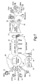
Figure 1 is a schematic view of a mobile telecommunications network in a conference call configuration with mobile transmitting/receiving units, each unit having a spatial processor, and -
Figure 2 shows a time frame transmitted in the downlink to a receiving mobile unit. - An embodiment of the invention in the circuit switched (CS) domain will initially be described.
- Referring first to
Figure 1 , the network is a GSM network including a plurality of mobile transmitter/receiver units of which five 10, 11, 12, 13, 14 are shown inFigure 1 . The network includes a mobile switching centre (MSC) 15, a base station controller (BSC) 16 and a plurality of base transceiver stations (BTS), one of which is shown at 17. - The MSC 15 includes a
conference bridge 18 that permits the plurality ofmobile units mobile unit conference bridge 18 allows the voice components received in the uplink from eachmobile unit - Speech is encoded by a multi-channel variable bitrate audio/
speech coder 30 in theconference bridge 18. Such acoder 30 produces an optimal bitstream for conveying the speech component to a receivingunit BSC 16 and aBTS 17 to a receivingunit 14. The speech data from eachmobile unit downlink channel 20. Each sub-channel includes a tagging identifier that identifies the transmitting unit. In general, one sub-channel will be carrying the speech of the current speaker and "silent" sub-channels for each of the other speakers (usually only one participant in the conference call speaks at a time). - The
coder 30 compresses the speech data from themobile units - At the receiving
unit 14 the downlink channel is received and decompressed. The sub-channels and the respective tags associated therewith are then extracted from the received data. The sub-channels are passed to aspatial processor 21. Thespatial processor 21 uses the tagging identifier and the coded speech signal to generate a analogue spatially resolved audio signal characteristic of thetransmitter unit unit 14 has stereoloud speakers 26 then the spatial orientation of the signals will be mainly located in front of the person using the receivingunit 14 as seen inFigure 1 , assuming the unit is held in front of the person. Better spatial separation in 3D around the person (that is, in a 3D space around the person) may be obtained using, for example, stereo headphones. Suchspatial processors 21 are known and will not be described in further detail. - The analogue spatial audio signal produced at the receiving
unit 14 may be a 3-D signal lying in an imaginary sphere around the receiving person. Alternatively, this may be a 2-D signal lying in an imaginary circle around the receiving person. It has been found that, in general 2-D signals in front of the receiving person are the most easily differentiated since the human body is best able to distinguish sounds over the front hemisphere of the body. The use of a 2-D or 3-D signal allows the user to distinguish more easily between participants and provides a more natural listening environment so reducing listening fatigue. It would also allow louder speakers to be moved further away and to move softer speakers closer. It gives the potential for a large number of conference participants due to the extended sound field and, since no background noise is received, increases the illegibility. - It is possible to use only stereo panning in which the audio signals were chosen from a left ear signal, a right ear signal and a left and right ear signal and possibly mid-left and mid-right signals.
- In accordance with an important feature of this embodiment of the invention, the tagging identifiers each comprise an embedded watermarked tag in the speech data of incoming calls which allows the users to be distinguished. The tags are added to each incoming uplink channel by watermarking
processors 32. The watermarking is preferably (though not necessarily) performed prior to compression by thecoder 30. The watermarking performed by thewatermarking processors 32 is resistant to the compression process performed by thecoder 30, and to the decompression process performed by the receivingmobile unit 14. That is, the watermark tags inserted by thewatermarking processors 32 are recognisable and intelligible by themobile unit 14 after compression and decompression. The tag may be a basic binary number. -
Figure 2 shows a time frame in accordance with this embodiment of the invention transmitted in the downlink channel to the receivingmobile unit 14. Thetime frame 34 comprises aheader 36, afooter 38 and an information part (payload) 40. In the embodiment theinformation part 40 comprises information representing speech data from any ofmobile units information part 42 may comprise speech data from themobile unit 10. Embedded within that speech data is a watermark tag representing the identity of themobile unit 10. - Embedding a basic binary number into the speech data itself by use of compression resistant watermarking technology provides an advantageous mechanism for each individual incoming uplink channel to the
conference bridge 18 to be "tagged" and assigned to a particular user. - As discussed above, when arriving at the
conference bridge 18, each incoming line from themobile units - The tagging information is hidden within the audio data in a format that is inaudible to a listener (i.e. outside the range of human perception), but can be detected and decoded by the receiving mobile unit. This hidden information, or watermark, could be used to communicate not only participant tags, but also identity information and other meta data.
- The following water marking schemes may be used, for example.
- The DC watermarking scheme hides watermark data in lower frequency components of the audio signal, which are below the perceptual threshold of the human auditory system. However there are issues as to whether compression algorithms that are based on removing these inaudible parts of audio signals would remove all trace of the watermark.
- This DC watermarking scheme has some major limitations with regards to robustness and data density. The robustness of the scheme can be increased somewhat by utilising longer audio files, by inserting the watermark signal multiple times, which will aid in extraction, and also in error correction if the signal is manipulated.
- In order to attain higher hidden data density in the watermarked signal, more advanced techniques may be used such as spread spectrum, phase encoding, or echo hiding. The highest rate and most versatile and reliable watermarking scheme may comprise a combination of all of the above, allowing the software to capitalise on the strengths of each technique when processing the unmarked audio.
- This watermarking technique exploits the human auditory system's lack of sensitivity to absolute phase changes by encoding the watermark data in an artificial phase signal.
- Phase encoding works by breaking the audio signal into frames, and performing spectral analysis on each frame. Once the spectrum has been computed, the magnitude and phase of consecutive frames are compared, and an artificial phase signal is created to transmit data. The artificial phase is modulated in with the phase from each frame, and the new phase frames are combined to form the watermarked signal.
- The modified phase frames can also be smoothed to limit the amount of distortion present in the marked signal, but in minimising distortion, the data rate of the watermark is constrained respectively.
- The phase encoding watermarking technique offers higher data rates over the previous method, averaging from 8 to 32 bits per second; in comparison to DC watermarking that may only offer 11.1 bits per second. This technique is also increasingly effective in the presence of noise.
- This watermarking technique relies on direct sequence spread spectrum (DSSS) to spread the watermarked signal over the entire audible frequency spectrum such that it approximates white noise, at a power level as to be inaudible. A pseudorandom sequence (chip) is used to modulate a carrier wave which creases the spread signal watermark code. This code is attenuated to a level roughly equal to 0.5% of the dynamic range of the original audio file, before being mixed with the original.
- The data rate from this technique is much lower than previous methods, and averages around 4 bits per second. The low data rate is compensated by the robustness of this algorithm due to high noise immunity.
- The echo data hiding techniques relies on distorting an audio signal in a way that is perceptually dismissed by the human auditory system as environmental distortion.
- The original audio signal is copied into two segments (kernels), one that leads the original signal in time, and one that lags. Each kernel represents either a zero or a one bit for watermark data transmission. The bit stream of watermark data is used to mix the two kernels together. The signals are mixed with gradually sloped transitions to reduce distortion.
- Some alternative embodiments will now be described.
- It is possible that the systems described above could be implemented a CS uplink and a packed switched (PS) downlink, or with a PS uplink and downlink.
- In the embodiment described each unit is a mobile telecommunications device. However, it should be appreciated that the units need not be mobile telecommunications devices; one or more of the units may be fixed terminals - for example terminals connected to the PSTN by a cable.
- The system may also be implemented in a UMTS (3G network) or any other mobile or cellular telecommunications network - such as a 2G (GSM), 4G (LTE/SAE) or VoIP network - in which at least some of the terminals or units communicate wirelessly with the network.
- In the embodiment described in detail, the received signal is decompressed prior to extraction of the watermarks. However, the watermarks may instead be extracted prior to decompression.
Claims (33)
- A method of performing a call in a telecommunication system having a plurality of transmitter/receiver units registered with a telecommunications network, the method including:receiving in the network an uplink signal representing detected sound from an originating unit,generating a downlink signal by encoding said uplink signal such that data indicative of a tag corresponding to the originating unit is embedded in a payload of said downlink signal, which payload conveys the detected sound,receiving the downlink signal, andextracting said embedded tag from the downlink signal in order to identify the originating unit corresponding to the tag.
- A method according to claim 1, including producing from said downlink signal a spatially resolved audio signal characteristic of said originating unit corresponding to said tag.
- A method according to claim 1 or 2, wherein the tag is embedded in the payload by watermarking the payload.
- A method according to claim 1,2 or 3, wherein the telecommunication system comprises three or more of said transmitter/receiver units.
- A method according to claim 1,2,3 or 4, wherein the telecommunications network comprises a mobile or cellular telecommunications network.
- A method according to claim 1, wherein the uplink signal is compressed.
- A method according to claim 1,2,3,4,5 or 6, including decompressing the downlink signal.
- A method of performing a call in a telecommunications network, the method including:receiving in the uplink speech data from a first terminal registered with the telecommunications network;receiving in the uplink speech data from a second terminal registered with the telecommunications network;adding a watermark to the received speech data from the first terminal to generate watermarked speech data of the first terminal;adding a watermark to the received speech data from the second terminal to generate watermarked speech data of the second terminal;generating a downlink signal for a receiving terminal registered with the network including both the watermarked speech data of the first terminal and the watermarked speech data of the second terminal;receiving the downlink signal at the receiving terminal;identifying the watermarked speech data of the first terminal; andidentifying the watermarked speech data of the second terminal.
- A method according to claim 8, including producing at the receiving terminal a spatially resolved audio signal in which the uplink speech data from the first terminal and the uplink speech data from the second terminal are reproduced at distinct locations in a two-dimensional or three-dimensional space.
- A method according to any one of claims 2 to 7 and 9 wherein the spatially resolved audio signal is generated by stereo-panning.
- A method according to any one of claims 2 to 7, 9 and 10 wherein the spatially resolved audio signal is generated by 2D or 3D virtualised audio.
- A method according to any one of claims 1 to 11 wherein the uplink and/or downlink data is transmitted in the CS domain.
- A method according to any one of claims 1 to 11 wherein the uplink and/or downlink data is transmitted in the PS domain.
- A method according to any one of claims 2 to 7, 9 and 10 wherein the spatially resolved analogue audio signal is produced by a stereo sound source at the receiving unit.
- A method according to any one of claims 8 to 14, wherein the downlink signal includes a frame comprising a header and/or footer and a payload, and wherein the watermark is embedded in the payload.
- Apparatus for performing a call in a telecommunication system having a plurality of transmitter/receiver units registered with a telecommunications network, the method including:means for receiving an uplink signal representing detected sound from an originating unit,means for generating a downlink signal, the generating means being operable to encode said uplink signal such that data indicative of a tag corresponding to the originating unit is embedded in a payload of said downlink signal, which payload conveys the detected sound, the embedded tag being extractable from the payload in order to identify the originating unit corresponding to the tag.
- Apparatus according to claim 16, wherein said downlink signal enables production of a spatially resolved audio signal characteristic of said originating unit corresponding to said tag in a receiving unit.
- Apparatus according to claim 16 or 17, wherein the generating means is operable to embed the tag in the payload by watermarking the payload.
- Apparatus according to claim 16,17 or 18, wherein the telecommunication system comprises three or more of said transmitter/receiver units.
- Apparatus according to claim 16,17,18 or 19, wherein the telecommunications network comprises a mobile or cellular telecommunications network.
- Apparatus according to claim 16,17,18,19 or 20, including means for compressing the uplink signal.
- Apparatus for performing a conference call in a telecommunications network, the method including:means for receiving in the uplink speech data from a first terminal registered with the telecommunications network;means for receiving in the uplink speech data from a second terminal registered with the telecommunications network.means for adding a watermark to the received speech data from the first terminal to generate watermarked speech data of the first terminal;means for adding a watermark to the received speech data from the second terminal to generate watermarked speech data of the second terminal; andmeans for generating a downlink signal for a receiving terminal registered with the network including both the watermarked speech data of the first terminal and the watermarked speech data of the second terminal such that the receiving terminal can identify the watermarked speech data of the first terminal and identify the watermarked speech data of the second terminal.
- Apparatus according to claim 22, wherein said downlink signal enables the production of a spatially resolved audio signal in which the uplink speech data from the first terminal and the uplink speech data from the second terminal are reproduced at distinct locations in a two-dimensional or three-dimensional space.
- Apparatus according to any one of claims 17 to 21 or 23, wherein the spatially resolved audio signal is generated by stereo-panning.
- Apparatus according to any one of claims 17 to 21, 23 or 24, wherein the spatially resolved audio signal is generated by 2D or 3D virtualised audio.
- Apparatus according to any one of claims 16 to 25 wherein the uplink and/or downlink data is transmitted in the CS domain.
- Apparatus according to any one of claims 16 to 25 wherein the uplink and/or downlink data is transmitted in the PS domain.
- Apparatus according to any one of claims 17 to 21 or 23 to 27, wherein the spatially resolved analogue audio signal is produced by a stereo sound source at the receiving unit.
- Apparatus according to any one of claims 22 to 28, wherein the downlink signal includes a frame comprising a header and/or footer and a payload, and wherein the watermark is embedded in the payload.
- Apparatus according to any one of claims 16 to 21, further including the originating unit.
- Apparatus according to any one of claims 16 to 21, further including the receiving unit.
- Apparatus according to any one of claims 22 to 29, further including the first and/or second terminal.
- Apparatus according to any one of claims 22 to 29 and 32, further including the receiving terminal.
Applications Claiming Priority (1)
| Application Number | Priority Date | Filing Date | Title |
|---|---|---|---|
| GB0714131.0A GB2452021B (en) | 2007-07-19 | 2007-07-19 | identifying callers in telecommunication networks |
Publications (2)
| Publication Number | Publication Date |
|---|---|
| EP2063622A1 true EP2063622A1 (en) | 2009-05-27 |
| EP2063622B1 EP2063622B1 (en) | 2013-05-15 |
Family
ID=38476652
Family Applications (1)
| Application Number | Title | Priority Date | Filing Date |
|---|---|---|---|
| EP08104797.9A Not-in-force EP2063622B1 (en) | 2007-07-19 | 2008-07-18 | Identifying callers in telecommunications networks |
Country Status (3)
| Country | Link |
|---|---|
| US (1) | US8422406B2 (en) |
| EP (1) | EP2063622B1 (en) |
| GB (1) | GB2452021B (en) |
Families Citing this family (19)
| Publication number | Priority date | Publication date | Assignee | Title |
|---|---|---|---|---|
| US7904067B1 (en) * | 2004-12-15 | 2011-03-08 | Syniverse Icx Corporation | Method and apparatus for enabling call originator to select a notification on a telecommunications device |
| EP2337328B1 (en) * | 2008-10-20 | 2014-12-03 | Huawei Device Co., Ltd. | Method, system and apparatus for processing 3d audio signal |
| GB2470059A (en) * | 2009-05-08 | 2010-11-10 | Nokia Corp | Multi-channel audio processing using an inter-channel prediction model to form an inter-channel parameter |
| US20130051560A1 (en) * | 2011-08-30 | 2013-02-28 | Raytheon Company | 3-Dimensional Audio Projection |
| EP2565667A1 (en) * | 2011-08-31 | 2013-03-06 | Friedrich-Alexander-Universität Erlangen-Nürnberg | Direction of arrival estimation using watermarked audio signals and microphone arrays |
| US9374448B2 (en) * | 2012-05-27 | 2016-06-21 | Qualcomm Incorporated | Systems and methods for managing concurrent audio messages |
| US9191516B2 (en) * | 2013-02-20 | 2015-11-17 | Qualcomm Incorporated | Teleconferencing using steganographically-embedded audio data |
| US9172908B2 (en) * | 2013-06-18 | 2015-10-27 | Microsoft Technology Licensing, Llc | Unpaired devices |
| US9621713B1 (en) * | 2014-04-01 | 2017-04-11 | Securus Technologies, Inc. | Identical conversation detection method and apparatus |
| US9357168B1 (en) | 2014-08-25 | 2016-05-31 | Google Inc. | Facilitating video conferences |
| WO2017055434A1 (en) * | 2015-09-30 | 2017-04-06 | British Telecommunications Public Limited Company | Call recording |
| GB2542821B (en) * | 2015-09-30 | 2020-04-08 | British Telecomm | Call recording |
| EP3301673A1 (en) * | 2016-09-30 | 2018-04-04 | Nxp B.V. | Audio communication method and apparatus |
| US10419511B1 (en) * | 2016-10-04 | 2019-09-17 | Zoom Video Communications, Inc. | Unique watermark generation and detection during a conference |
| US10614826B2 (en) | 2017-05-24 | 2020-04-07 | Modulate, Inc. | System and method for voice-to-voice conversion |
| US11269976B2 (en) * | 2019-03-20 | 2022-03-08 | Saudi Arabian Oil Company | Apparatus and method for watermarking a call signal |
| WO2021030759A1 (en) * | 2019-08-14 | 2021-02-18 | Modulate, Inc. | Generation and detection of watermark for real-time voice conversion |
| JP2023546989A (en) | 2020-10-08 | 2023-11-08 | モジュレイト インク. | Multi-stage adaptive system for content moderation |
| US12341619B2 (en) | 2022-06-01 | 2025-06-24 | Modulate, Inc. | User interface for content moderation of voice chat |
Citations (4)
| Publication number | Priority date | Publication date | Assignee | Title |
|---|---|---|---|---|
| WO2001057868A1 (en) * | 2000-02-01 | 2001-08-09 | Koninklijke Philips Electronics N.V. | Embedding a watermark in an information signal |
| US20030044002A1 (en) | 2001-08-28 | 2003-03-06 | Yeager David M. | Three dimensional audio telephony |
| WO2004006475A2 (en) * | 2002-07-04 | 2004-01-15 | Nokia Corporation | Managing a packet switched conference call |
| GB2416955A (en) | 2004-07-28 | 2006-02-08 | Vodafone Plc | Conference calls in mobile networks |
Family Cites Families (18)
| Publication number | Priority date | Publication date | Assignee | Title |
|---|---|---|---|---|
| US7562392B1 (en) * | 1999-05-19 | 2009-07-14 | Digimarc Corporation | Methods of interacting with audio and ambient music |
| US6125115A (en) * | 1998-02-12 | 2000-09-26 | Qsound Labs, Inc. | Teleconferencing method and apparatus with three-dimensional sound positioning |
| US6457043B1 (en) * | 1998-10-23 | 2002-09-24 | Verizon Laboratories Inc. | Speaker identifier for multi-party conference |
| US6304648B1 (en) * | 1998-12-21 | 2001-10-16 | Lucent Technologies Inc. | Multimedia conference call participant identification system and method |
| US20030125954A1 (en) * | 1999-09-28 | 2003-07-03 | Bradley James Frederick | System and method at a conference call bridge server for identifying speakers in a conference call |
| EP1292090A1 (en) * | 2001-09-05 | 2003-03-12 | Motorola, Inc. | Conference calling with speaker identification |
| KR20040077713A (en) * | 2002-01-11 | 2004-09-06 | 코닌클리케 필립스 일렉트로닉스 엔.브이. | Generation of a watermark being unique to a receiver of a multicast transmission of multimedia |
| US20050135613A1 (en) * | 2002-05-10 | 2005-06-23 | Karlheinz Brandenburg | Device and method for generating encrypted data, for decrypting encrypted data and for generating re-signed data |
| US20050018828A1 (en) * | 2003-07-25 | 2005-01-27 | Siemens Information And Communication Networks, Inc. | System and method for indicating a speaker during a conference |
| US7305078B2 (en) * | 2003-12-18 | 2007-12-04 | Electronic Data Systems Corporation | Speaker identification during telephone conferencing |
| US7355623B2 (en) * | 2004-04-30 | 2008-04-08 | Microsoft Corporation | System and process for adding high frame-rate current speaker data to a low frame-rate video using audio watermarking techniques |
| EP1757041A1 (en) | 2004-06-01 | 2007-02-28 | Koninklijke Philips Electronics N.V. | Method, apparatuses and signal for transmitting/receiving information comprising primary and secondary messages in a same transmission |
| JP2008502194A (en) | 2004-06-02 | 2008-01-24 | コーニンクレッカ フィリップス エレクトロニクス エヌ ヴィ | Method and apparatus for embedding auxiliary information in a media signal |
| US7724885B2 (en) * | 2005-07-11 | 2010-05-25 | Nokia Corporation | Spatialization arrangement for conference call |
| US7961739B2 (en) * | 2005-07-21 | 2011-06-14 | Genband Us Llc | Systems and methods for voice over multiprotocol label switching |
| KR100953644B1 (en) * | 2006-01-19 | 2010-04-20 | 엘지전자 주식회사 | Method and apparatus for processing media signal |
| US7583956B2 (en) * | 2006-04-27 | 2009-09-01 | Sony Ericsson Mobile Communications Ab | System and method of conferencing endpoints |
| EP1954019A1 (en) * | 2007-02-01 | 2008-08-06 | Research In Motion Limited | System and method for providing simulated spatial sound in a wireless communication device during group voice communication sessions |
-
2007
- 2007-07-19 GB GB0714131.0A patent/GB2452021B/en active Active
-
2008
- 2008-07-18 EP EP08104797.9A patent/EP2063622B1/en not_active Not-in-force
- 2008-07-18 US US12/218,815 patent/US8422406B2/en not_active Expired - Fee Related
Patent Citations (5)
| Publication number | Priority date | Publication date | Assignee | Title |
|---|---|---|---|---|
| WO2001057868A1 (en) * | 2000-02-01 | 2001-08-09 | Koninklijke Philips Electronics N.V. | Embedding a watermark in an information signal |
| US20030044002A1 (en) | 2001-08-28 | 2003-03-06 | Yeager David M. | Three dimensional audio telephony |
| WO2003022001A1 (en) * | 2001-08-28 | 2003-03-13 | Motorola, Inc., A Corporation Of The State Of Delaware | Three dimensional audio telephony |
| WO2004006475A2 (en) * | 2002-07-04 | 2004-01-15 | Nokia Corporation | Managing a packet switched conference call |
| GB2416955A (en) | 2004-07-28 | 2006-02-08 | Vodafone Plc | Conference calls in mobile networks |
Non-Patent Citations (1)
| Title |
|---|
| KOK SOON PHUA ET AL: "Spatial speech coding for multi-teleconferencing", TENCON 99. PROCEEDINGS OF THE IEEE REGION 10 CONFERENCE CHEJU ISLAND, SOUTH KOREA 15-17 SEPT. 1999, PISCATAWAY, NJ, USA,IEEE, US, vol. 1, 15 September 1999 (1999-09-15), pages 313 - 316, XP010368216, ISBN: 978-0-7803-5739-6 * |
Also Published As
| Publication number | Publication date |
|---|---|
| GB2452021B (en) | 2012-03-14 |
| GB2452021A (en) | 2009-02-25 |
| US8422406B2 (en) | 2013-04-16 |
| GB0714131D0 (en) | 2007-08-29 |
| EP2063622B1 (en) | 2013-05-15 |
| US20090034704A1 (en) | 2009-02-05 |
Similar Documents
| Publication | Publication Date | Title |
|---|---|---|
| EP2063622B1 (en) | Identifying callers in telecommunications networks | |
| US10834252B2 (en) | Transcribing audio communication sessions | |
| US10964332B2 (en) | Audio communication method and apparatus for watermarking an audio signal with spatial information | |
| WO2008004056A2 (en) | Artificial bandwidth expansion method for a multichannel signal | |
| EP1324582A1 (en) | Teleconferencing Bridge with comb filtering for spatial sound image | |
| WO2010125228A1 (en) | Encoding of multiview audio signals | |
| JP5912294B2 (en) | Video conferencing equipment | |
| CN111199745A (en) | Advertisement identification method, equipment, media platform, terminal, server and medium | |
| JP6608380B2 (en) | Communication system, method and apparatus with improved noise resistance | |
| CN100514394C (en) | Method, device and system for embedding/extracting data in voice code | |
| CN116312510A (en) | Near-end control method of remote conference device, remote conference system and related devices | |
| JP3898673B2 (en) | Audio communication system, method and program, and audio reproduction apparatus | |
| CN113035226A (en) | Voice call method, communication terminal, and computer-readable medium | |
| KR101990884B1 (en) | Method and Appartus for Improving Communication Quality between Heterogeneous Network | |
| US6954522B2 (en) | Caller identifying information encoded within embedded digital information | |
| CN100353777C (en) | Method and equipment for treating special sound class in communication system | |
| CN120913572A (en) | Voice processing method and system and intelligent glasses | |
| CN121098984A (en) | Microphone-based communication methods, systems, and storage media | |
| HK1232026B (en) | Communications systems, methods and devices having improved noise immunity | |
| HK1232026A1 (en) | Communications systems, methods and devices having improved noise immunity | |
| KR20100035205A (en) | High quality communication system and method thereof |
Legal Events
| Date | Code | Title | Description |
|---|---|---|---|
| PUAI | Public reference made under article 153(3) epc to a published international application that has entered the european phase |
Free format text: ORIGINAL CODE: 0009012 |
|
| AK | Designated contracting states |
Kind code of ref document: A1 Designated state(s): AT BE BG CH CY CZ DE DK EE ES FI FR GB GR HR HU IE IS IT LI LT LU LV MC MT NL NO PL PT RO SE SI SK TR |
|
| AX | Request for extension of the european patent |
Extension state: AL BA MK RS |
|
| 17P | Request for examination filed |
Effective date: 20091124 |
|
| 17Q | First examination report despatched |
Effective date: 20091218 |
|
| AKX | Designation fees paid |
Designated state(s): AT BE BG CH CY CZ DE DK EE ES FI FR GB GR HR HU IE IS IT LI LT LU LV MC MT NL NO PL PT RO SE SI SK TR |
|
| RBV | Designated contracting states (corrected) |
Designated state(s): AT BE BG CH CY CZ DE DK EE ES FI FR GB GR HR HU IE IS IT LI LT LU LV MC MT NL NO PL PT RO SE SI SK TR |
|
| REG | Reference to a national code |
Ref country code: DE Ref legal event code: R079 Ref document number: 602008024529 Country of ref document: DE Free format text: PREVIOUS MAIN CLASS: H04M0003560000 Ipc: H04M0003420000 |
|
| RIC1 | Information provided on ipc code assigned before grant |
Ipc: H04M 3/56 20060101ALI20120913BHEP Ipc: H04M 3/42 20060101AFI20120913BHEP Ipc: H04L 12/18 20060101ALI20120913BHEP |
|
| GRAP | Despatch of communication of intention to grant a patent |
Free format text: ORIGINAL CODE: EPIDOSNIGR1 |
|
| GRAS | Grant fee paid |
Free format text: ORIGINAL CODE: EPIDOSNIGR3 |
|
| GRAA | (expected) grant |
Free format text: ORIGINAL CODE: 0009210 |
|
| AK | Designated contracting states |
Kind code of ref document: B1 Designated state(s): AT BE BG CH CY CZ DE DK EE ES FI FR GB GR HR HU IE IS IT LI LT LU LV MC MT NL NO PL PT RO SE SI SK TR |
|
| REG | Reference to a national code |
Ref country code: CH Ref legal event code: EP Ref country code: GB Ref legal event code: FG4D |
|
| REG | Reference to a national code |
Ref country code: AT Ref legal event code: REF Ref document number: 612615 Country of ref document: AT Kind code of ref document: T Effective date: 20130615 |
|
| REG | Reference to a national code |
Ref country code: IE Ref legal event code: FG4D |
|
| REG | Reference to a national code |
Ref country code: DE Ref legal event code: R096 Ref document number: 602008024529 Country of ref document: DE Effective date: 20130711 |
|
| REG | Reference to a national code |
Ref country code: AT Ref legal event code: MK05 Ref document number: 612615 Country of ref document: AT Kind code of ref document: T Effective date: 20130515 |
|
| REG | Reference to a national code |
Ref country code: LT Ref legal event code: MG4D |
|
| REG | Reference to a national code |
Ref country code: NL Ref legal event code: VDEP Effective date: 20130515 |
|
| PG25 | Lapsed in a contracting state [announced via postgrant information from national office to epo] |
Ref country code: SE Free format text: LAPSE BECAUSE OF FAILURE TO SUBMIT A TRANSLATION OF THE DESCRIPTION OR TO PAY THE FEE WITHIN THE PRESCRIBED TIME-LIMIT Effective date: 20130515 Ref country code: NO Free format text: LAPSE BECAUSE OF FAILURE TO SUBMIT A TRANSLATION OF THE DESCRIPTION OR TO PAY THE FEE WITHIN THE PRESCRIBED TIME-LIMIT Effective date: 20130815 Ref country code: IS Free format text: LAPSE BECAUSE OF FAILURE TO SUBMIT A TRANSLATION OF THE DESCRIPTION OR TO PAY THE FEE WITHIN THE PRESCRIBED TIME-LIMIT Effective date: 20130915 Ref country code: SI Free format text: LAPSE BECAUSE OF FAILURE TO SUBMIT A TRANSLATION OF THE DESCRIPTION OR TO PAY THE FEE WITHIN THE PRESCRIBED TIME-LIMIT Effective date: 20130515 Ref country code: AT Free format text: LAPSE BECAUSE OF FAILURE TO SUBMIT A TRANSLATION OF THE DESCRIPTION OR TO PAY THE FEE WITHIN THE PRESCRIBED TIME-LIMIT Effective date: 20130515 Ref country code: PT Free format text: LAPSE BECAUSE OF FAILURE TO SUBMIT A TRANSLATION OF THE DESCRIPTION OR TO PAY THE FEE WITHIN THE PRESCRIBED TIME-LIMIT Effective date: 20130916 Ref country code: ES Free format text: LAPSE BECAUSE OF FAILURE TO SUBMIT A TRANSLATION OF THE DESCRIPTION OR TO PAY THE FEE WITHIN THE PRESCRIBED TIME-LIMIT Effective date: 20130826 Ref country code: GR Free format text: LAPSE BECAUSE OF FAILURE TO SUBMIT A TRANSLATION OF THE DESCRIPTION OR TO PAY THE FEE WITHIN THE PRESCRIBED TIME-LIMIT Effective date: 20130816 Ref country code: FI Free format text: LAPSE BECAUSE OF FAILURE TO SUBMIT A TRANSLATION OF THE DESCRIPTION OR TO PAY THE FEE WITHIN THE PRESCRIBED TIME-LIMIT Effective date: 20130515 Ref country code: LT Free format text: LAPSE BECAUSE OF FAILURE TO SUBMIT A TRANSLATION OF THE DESCRIPTION OR TO PAY THE FEE WITHIN THE PRESCRIBED TIME-LIMIT Effective date: 20130515 |
|
| PG25 | Lapsed in a contracting state [announced via postgrant information from national office to epo] |
Ref country code: PL Free format text: LAPSE BECAUSE OF FAILURE TO SUBMIT A TRANSLATION OF THE DESCRIPTION OR TO PAY THE FEE WITHIN THE PRESCRIBED TIME-LIMIT Effective date: 20130515 Ref country code: BG Free format text: LAPSE BECAUSE OF FAILURE TO SUBMIT A TRANSLATION OF THE DESCRIPTION OR TO PAY THE FEE WITHIN THE PRESCRIBED TIME-LIMIT Effective date: 20130815 Ref country code: HR Free format text: LAPSE BECAUSE OF FAILURE TO SUBMIT A TRANSLATION OF THE DESCRIPTION OR TO PAY THE FEE WITHIN THE PRESCRIBED TIME-LIMIT Effective date: 20130515 |
|
| PG25 | Lapsed in a contracting state [announced via postgrant information from national office to epo] |
Ref country code: LV Free format text: LAPSE BECAUSE OF FAILURE TO SUBMIT A TRANSLATION OF THE DESCRIPTION OR TO PAY THE FEE WITHIN THE PRESCRIBED TIME-LIMIT Effective date: 20130515 |
|
| PG25 | Lapsed in a contracting state [announced via postgrant information from national office to epo] |
Ref country code: BE Free format text: LAPSE BECAUSE OF FAILURE TO SUBMIT A TRANSLATION OF THE DESCRIPTION OR TO PAY THE FEE WITHIN THE PRESCRIBED TIME-LIMIT Effective date: 20130515 Ref country code: CZ Free format text: LAPSE BECAUSE OF FAILURE TO SUBMIT A TRANSLATION OF THE DESCRIPTION OR TO PAY THE FEE WITHIN THE PRESCRIBED TIME-LIMIT Effective date: 20130515 Ref country code: SK Free format text: LAPSE BECAUSE OF FAILURE TO SUBMIT A TRANSLATION OF THE DESCRIPTION OR TO PAY THE FEE WITHIN THE PRESCRIBED TIME-LIMIT Effective date: 20130515 Ref country code: EE Free format text: LAPSE BECAUSE OF FAILURE TO SUBMIT A TRANSLATION OF THE DESCRIPTION OR TO PAY THE FEE WITHIN THE PRESCRIBED TIME-LIMIT Effective date: 20130515 Ref country code: DK Free format text: LAPSE BECAUSE OF FAILURE TO SUBMIT A TRANSLATION OF THE DESCRIPTION OR TO PAY THE FEE WITHIN THE PRESCRIBED TIME-LIMIT Effective date: 20130515 |
|
| PG25 | Lapsed in a contracting state [announced via postgrant information from national office to epo] |
Ref country code: IT Free format text: LAPSE BECAUSE OF FAILURE TO SUBMIT A TRANSLATION OF THE DESCRIPTION OR TO PAY THE FEE WITHIN THE PRESCRIBED TIME-LIMIT Effective date: 20130515 Ref country code: MC Free format text: LAPSE BECAUSE OF FAILURE TO SUBMIT A TRANSLATION OF THE DESCRIPTION OR TO PAY THE FEE WITHIN THE PRESCRIBED TIME-LIMIT Effective date: 20130515 Ref country code: NL Free format text: LAPSE BECAUSE OF FAILURE TO SUBMIT A TRANSLATION OF THE DESCRIPTION OR TO PAY THE FEE WITHIN THE PRESCRIBED TIME-LIMIT Effective date: 20130515 Ref country code: RO Free format text: LAPSE BECAUSE OF FAILURE TO SUBMIT A TRANSLATION OF THE DESCRIPTION OR TO PAY THE FEE WITHIN THE PRESCRIBED TIME-LIMIT Effective date: 20130515 |
|
| REG | Reference to a national code |
Ref country code: CH Ref legal event code: PL |
|
| PLBE | No opposition filed within time limit |
Free format text: ORIGINAL CODE: 0009261 |
|
| STAA | Information on the status of an ep patent application or granted ep patent |
Free format text: STATUS: NO OPPOSITION FILED WITHIN TIME LIMIT |
|
| 26N | No opposition filed |
Effective date: 20140218 |
|
| REG | Reference to a national code |
Ref country code: IE Ref legal event code: MM4A |
|
| PG25 | Lapsed in a contracting state [announced via postgrant information from national office to epo] |
Ref country code: LI Free format text: LAPSE BECAUSE OF NON-PAYMENT OF DUE FEES Effective date: 20130731 Ref country code: CH Free format text: LAPSE BECAUSE OF NON-PAYMENT OF DUE FEES Effective date: 20130731 |
|
| REG | Reference to a national code |
Ref country code: DE Ref legal event code: R097 Ref document number: 602008024529 Country of ref document: DE Effective date: 20140218 |
|
| PG25 | Lapsed in a contracting state [announced via postgrant information from national office to epo] |
Ref country code: IE Free format text: LAPSE BECAUSE OF NON-PAYMENT OF DUE FEES Effective date: 20130718 |
|
| REG | Reference to a national code |
Ref country code: FR Ref legal event code: PLFP Year of fee payment: 8 |
|
| PG25 | Lapsed in a contracting state [announced via postgrant information from national office to epo] |
Ref country code: TR Free format text: LAPSE BECAUSE OF FAILURE TO SUBMIT A TRANSLATION OF THE DESCRIPTION OR TO PAY THE FEE WITHIN THE PRESCRIBED TIME-LIMIT Effective date: 20130515 Ref country code: CY Free format text: LAPSE BECAUSE OF FAILURE TO SUBMIT A TRANSLATION OF THE DESCRIPTION OR TO PAY THE FEE WITHIN THE PRESCRIBED TIME-LIMIT Effective date: 20130515 Ref country code: MT Free format text: LAPSE BECAUSE OF FAILURE TO SUBMIT A TRANSLATION OF THE DESCRIPTION OR TO PAY THE FEE WITHIN THE PRESCRIBED TIME-LIMIT Effective date: 20130515 |
|
| PG25 | Lapsed in a contracting state [announced via postgrant information from national office to epo] |
Ref country code: HU Free format text: LAPSE BECAUSE OF FAILURE TO SUBMIT A TRANSLATION OF THE DESCRIPTION OR TO PAY THE FEE WITHIN THE PRESCRIBED TIME-LIMIT; INVALID AB INITIO Effective date: 20080718 Ref country code: LU Free format text: LAPSE BECAUSE OF NON-PAYMENT OF DUE FEES Effective date: 20130718 |
|
| PGFP | Annual fee paid to national office [announced via postgrant information from national office to epo] |
Ref country code: FR Payment date: 20150626 Year of fee payment: 8 |
|
| PGFP | Annual fee paid to national office [announced via postgrant information from national office to epo] |
Ref country code: DE Payment date: 20150721 Year of fee payment: 8 Ref country code: GB Payment date: 20150721 Year of fee payment: 8 |
|
| REG | Reference to a national code |
Ref country code: DE Ref legal event code: R119 Ref document number: 602008024529 Country of ref document: DE |
|
| GBPC | Gb: european patent ceased through non-payment of renewal fee |
Effective date: 20160718 |
|
| PG25 | Lapsed in a contracting state [announced via postgrant information from national office to epo] |
Ref country code: DE Free format text: LAPSE BECAUSE OF NON-PAYMENT OF DUE FEES Effective date: 20170201 Ref country code: FR Free format text: LAPSE BECAUSE OF NON-PAYMENT OF DUE FEES Effective date: 20160801 |
|
| REG | Reference to a national code |
Ref country code: FR Ref legal event code: ST Effective date: 20170331 |
|
| PG25 | Lapsed in a contracting state [announced via postgrant information from national office to epo] |
Ref country code: GB Free format text: LAPSE BECAUSE OF NON-PAYMENT OF DUE FEES Effective date: 20160718 |