EP2063100A2 - Fuel pump control for a direct injection internal combustion engine - Google Patents
Fuel pump control for a direct injection internal combustion engine Download PDFInfo
- Publication number
- EP2063100A2 EP2063100A2 EP08019839A EP08019839A EP2063100A2 EP 2063100 A2 EP2063100 A2 EP 2063100A2 EP 08019839 A EP08019839 A EP 08019839A EP 08019839 A EP08019839 A EP 08019839A EP 2063100 A2 EP2063100 A2 EP 2063100A2
- Authority
- EP
- European Patent Office
- Prior art keywords
- valve
- pump
- coil
- control circuit
- fuel
- Prior art date
- Legal status (The legal status is an assumption and is not a legal conclusion. Google has not performed a legal analysis and makes no representation as to the accuracy of the status listed.)
- Withdrawn
Links
Images


Classifications
-
- F—MECHANICAL ENGINEERING; LIGHTING; HEATING; WEAPONS; BLASTING
- F02—COMBUSTION ENGINES; HOT-GAS OR COMBUSTION-PRODUCT ENGINE PLANTS
- F02M—SUPPLYING COMBUSTION ENGINES IN GENERAL WITH COMBUSTIBLE MIXTURES OR CONSTITUENTS THEREOF
- F02M59/00—Pumps specially adapted for fuel-injection and not provided for in groups F02M39/00 -F02M57/00, e.g. rotary cylinder-block type of pumps
- F02M59/20—Varying fuel delivery in quantity or timing
- F02M59/36—Varying fuel delivery in quantity or timing by variably-timed valves controlling fuel passages to pumping elements or overflow passages
- F02M59/366—Valves being actuated electrically
-
- F—MECHANICAL ENGINEERING; LIGHTING; HEATING; WEAPONS; BLASTING
- F04—POSITIVE - DISPLACEMENT MACHINES FOR LIQUIDS; PUMPS FOR LIQUIDS OR ELASTIC FLUIDS
- F04B—POSITIVE-DISPLACEMENT MACHINES FOR LIQUIDS; PUMPS
- F04B49/00—Control, e.g. of pump delivery, or pump pressure of, or safety measures for, machines, pumps, or pumping installations, not otherwise provided for, or of interest apart from, groups F04B1/00 - F04B47/00
- F04B49/22—Control, e.g. of pump delivery, or pump pressure of, or safety measures for, machines, pumps, or pumping installations, not otherwise provided for, or of interest apart from, groups F04B1/00 - F04B47/00 by means of valves
- F04B49/24—Bypassing
- F04B49/243—Bypassing by keeping open the inlet valve
-
- F—MECHANICAL ENGINEERING; LIGHTING; HEATING; WEAPONS; BLASTING
- F02—COMBUSTION ENGINES; HOT-GAS OR COMBUSTION-PRODUCT ENGINE PLANTS
- F02M—SUPPLYING COMBUSTION ENGINES IN GENERAL WITH COMBUSTIBLE MIXTURES OR CONSTITUENTS THEREOF
- F02M2200/00—Details of fuel-injection apparatus, not otherwise provided for
- F02M2200/09—Fuel-injection apparatus having means for reducing noise
Definitions
- the present invention relates to the control of a fuel pump for a direct injection gasoline internal combustion engine.
- Direct injection internal combustion engines i.e. engines in which the fuel injector injects the fuel directly into the combustion chamber, exhibit several advantages over the more conventional port-fuel injected internal combustion chambers. Most notably, direct injection engines enjoy increased fuel economy over other types of internal combustion engines. Direct injection internal combustion engines, however, do exhibit some inherent disadvantages.
- a primary source of noise, especially at low speeds, for a direct injection engine arises from the fuel pump for the engine.
- a pump piston in a fuel pump is reciprocally driven by a cam having two or more typically three or four lobes. These lobes are all symmetrical and all contact the piston pump, usually through a roller. Upon rotation of the cam, the lobes cause the piston to move reciprocally within the pump housing.
- the fuel pump also includes an inlet valve which is movable between an open position and a closed position by an electric coil or solenoid. In its open position, fuel flows to or from a pump chamber within the pump housing through the valve port. Conversely, when the valve is moved to its closed position, the piston during a pump cycle pumps pressurized fuel through a check valve and into the fuel rail for the engine.
- valve when the valve is moved to its open position by the electric coil or solenoid, the valve contacts a valve stop and produces an audible tick. Conversely, whenever the valve slams to a closed position during a pumping or pressurization portion of the pumping cycle, the contact between the valve head and the valve seat also causes audible noise. This noise is particularly prevalent at low speeds.
- the rapid closure of the fuel valve is required for proper engine operation at high speed operation of the engine since the fuel pump operates at or near 100% of its capacity. However, such rapid closure of the fuel valve is not required at lower speeds, such as idle, due to the lower fuel requirements of the engine.
- the present invention provides a number of strategies for the fuel pump in a direct injection internal combustion engine which overcomes the above-mentioned disadvantages of the previously known fuel pumps.
- the fuel pump of the present invention includes a piston which is reciprocally mounted within a pump chamber formed in a pump housing.
- a valve is mounted within the pump housing and includes a fuel port that is open to the pump chamber as well as the fuel tank. This fuel valve is movable between an open and a closed position by an electric coil or solenoid.
- valve With the valve in either a fully or partially open position, i.e. with the valve head spaced from the valve seat, reciprocation of the pump piston within the pump chamber during the suction portion of the pumping cycle inducts fuel from the fuel tank through the fuel port and into the fuel chamber. If the fuel valve is opened during a portion of the pressurization cycle for the pump, the pump piston pumps fuel from the pump chamber through the valve port and back to the fuel tank.
- the pump chamber is fluidly connected by a check valve to the fuel rails for the engine. Consequently, in this condition, the pump piston pressurizes the fuel rail in the desired fashion.
- a control circuit controls the energization of the coil or solenoid to reduce the pump noise during the operation of the invention.
- the control circuit deenergizes the coil in a ramp function during valve closure whenever the engine speed is less than a predetermined threshold. This, in turn, minimizes the speed of impact of the valve head against the valve seat during closure, or impact of the valve against a mechanical stop during valve opening, and thereby reduces the pump noise.
- control circuit maintains the energization of the coil, and thus maintains the valve in an open position, during a plurality of pressurization cycles of the pump during a low speed engine condition. Since the valve head does not impact the valve seat nor the valve impact the mechanical stop while the valve is held in an open position, noise from the fuel pump is reduced.
- control circuit actuates the valve to move the valve to an open position at the time that the valve is open a maximum amount by hydraulic pressure during the suction intake portion of the pump cycle. This also minimizes the speed of impact of the valve against the mechanical stop and thus reduces pump noise.
- the actuation of the coil or solenoid is controlled by a pulse width modulated current signal.
- the width of the first pulse to the coil is reduced as contrasted to subsequent current pulses to minimize the rate of opening of the valve at low engine speeds, and thus the rate of impact of the valve against the mechanical stop.
- the pump 20 includes a pump housing 24 which defines a pump chamber 26.
- the pump chamber 26 is fluidly connected through a valve port 28 to a fuel tank 30.
- the pump chamber 26 is also fluidly connected to the fuel rail for the engine 22 through a check valve 32.
- a pump piston 34 is reciprocally mounted within the pump chamber 26.
- This pump piston 34 is reciprocally driven by a cam 36 typically having three or more lobes 38.
- the cam 36 is mechanically coupled to the piston 34 by a roller 40 which follows an outer surface of the cam 36.
- This roller 40 is maintained in contact with the cam 36 by a spring 42 so that as the engine 22 rotatably drives the cam 36, the cam 36 reciprocally displaces the piston 34 in the pump chamber 26.
- the fuel pump 20 further includes a valve 50 having a valve head 52 which cooperates with a valve seat 54 which forms the valve port 28.
- An electric coil 56 upon energization, moves the valve 50 to an open position in which the valve head 52 is spaced from the valve seat 54 thus opening the port 28.
- the valve 50 contacts a mechanical stop 58 which limits the extension of the valve 50 in its open position as shown in FIG. 1 .
- a spring 60 and hydraulic force returns the valve 50 to its closed position, illustrated in FIG. 3 , in which the valve head 52 contacts the valve seat 54 and closes the fluid port 28.
- a control circuit 62 controls the energization of the coil 56 to move the coil between its open position, illustrated in FIGS. 1 and 2 , and its closed position, illustrated in FIG. 3 .
- the operation of the control circuit 62 will be subsequently described in greater detail.
- the pump piston 34 In operation, during the suction portion of the pumping cycle, i.e. when the cam 36 moves the pump piston 34 away from the pump chamber 26, the pump piston 34 inducts fuel from the fuel tank 30 through the fuel port 28 and into the pump chamber 26. During this suction portion of the pumping cycle, the hydraulic pressure caused by the fuel flow from the fuel tank 30 into the pump chamber 26 maintains the valve 50 in a partially open position.
- the control circuit 62 energizes the coils 56 and moves the valve 50 to an open position.
- the control circuit 62 maintains the valve 50 in an open position during the initial portion of the pressurization cycle.
- the reciprocation of the pump piston 34 into the pump chamber 26 thus pumps fuel from the pump chamber 26, through the fuel port 28 and back to the fuel tank 30.
- the control circuit 62 deenergizes the coils 56 thus causing the valve 50 to move to its closed position illustrated in FIG. 3 .
- the increasing pressure within the pump chamber 26 forces the check valve 32 to an open position and pumps the fuel from the pump chamber 26 to the fuel rail of the direct injection engine 22.
- the engine control circuit 62 energizes the coil 56 and holds the valve 50 open over multiple pumping cycles 72, i.e. wherein each pumping cycle represents one complete reciprocation of the pump piston 34 in the pump housing 24.
- a graph 70 of the pump current is illustrated through numerous pump cycles 72. Since the valve is moved to its open position only once over multiple pump cycles and thus causes contact between the valve 50 and its mechanical stop 58 only once over multiple cycles, the audible noise from such valve opening and closing (and pressurization) is reduced. Furthermore, even though the pump 20 provides less fuel pressure to the engine 22 since the valve 50 is held in its open position, such reduced fuel pumping capacity from the fuel pump 20 is acceptable due to the reduced fuel demands of the engine 22 at low speeds.
- FIG. 5 illustrates a graph 74 of the current to the coils 56 and in which the current is reduced during the suction portion of each pumping cycle as shown at 76.
- the valve 50 remains fully opened during the suction portion of the pumping cycle due to the co-operating hydraulic pressure caused by the fuel inflow into the pumping chamber 26 during the suction portion of each pumping cycle.
- control circuit 62 deenergizes the coil 56 after a certain maximum amount of time as shown at 80 in graph 78.
- Such deenergization of the coils is illustrated at 80 in FIG. 6 and such deenergization protects the coils 56 from overheating.
- FIG. 7 a still further modification is shown of the current control by the control circuit 62 for the coils 56.
- a graph 82 of the current flow for the coil 56 is shown in which the current flow is reduced during each suction portion of the pumping cycle in a fashion similar to FIG. 5 .
- the control circuit 62 also deenergizes the coils 56 after a certain maximum time period in a fashion similar to that illustrated in FIG. 6 . Consequently, although the graph 82 of current flow in FIG. 7 shows a reduction in the current flow during each suction portion of the pumping cycle, a larger reduction of the current flow, i.e. a current to zero, also occurs after each maximum time period as shown at 84.
- the overall number of impacts between the valve 50 and its mechanical stop 58 or between the valve head 52 and the valve seat 54 is reduced thus reducing the overall noise from the fuel pump during low speed engine operating conditions.
- FIG. 8 a still further strategy is illustrated for the control of the energization of the coil 56 by the control circuit 62.
- the movement of the valve is shown by graph 90 in which the valve 50 moves from a closed position, illustrated at position 92, to a partially open position, illustrated at 94, during the intake portion of the pump cycle.
- This partial opening of the valve 50 is caused by the hydraulic pressure of the incoming fuel flow to the pump chamber 26 during the suction cycle.
- the control circuit 62 energizes the coils 56 at time 96 thus causing the valve 50 to move to its fully open position illustrated at 98.
- the speed of impact of the valve 70 against its mechanical stop 58 is reduced.
- FIG. 9 a still further strategy to reduce fuel pump noise at low engine speed is illustrated as a graph 100 of the coil current as a function of time.
- the control circuit 62 utilizes a ramp function 102 to energize the coil and move the valve 50 to its open position.
- the ramp 102 thus effectively reduces the speed of impact of the valve 50 against its mechanical stop 58 at low engine speeds and thus reduces the pump noise.
- control circuit 62 also optionally deenergizes the coil 56 from its fully energized position, illustrated at 104, into a deenergized condition illustrated at 106 through a ramp function 108.
- the control circuit 62 also optionally deenergizes the coil 56 from its fully energized position, illustrated at 104, into a deenergized condition illustrated at 106 through a ramp function 108.
- the control circuit preferably energizes the coil 56 through pulse width modulation of the current.
- the speed of opening of the valve 50 at low engine speeds may be controlled by the control circuit 62 by reducing the pulse width of the current signal to the coil 56 during the initiation of the valve opening as shown in graph 110.
- the control circuit 62 reduces the speed of impact, and thus the noise, of the valve 50 against its mechanical stop 58.
- the pulse width can be progressively stepped down curing solenoid valve closing to reduce impact of valve head 52 against valve seat 54.
- the fuel noise from the fuel pump may be reduced by varying the lobe design for the pump. More specifically, as illustrated in FIGS. 12 and 13, the cam 36 of the fuel pump 20 includes three lobes 136, 138 and 140 which are angularly equidistantly spaced around the cam 134 and each of the lobes 136-140 are of the same angular length. Each lobe 136-140 reciprocates the pumping piston 34 through one complete pumping cycle.
- the lobe 140 is not symmetrical with the lobes 136 and 138.
- the asymmetry of the lobe 140 reduces pump noise caused by the pump suction.
- the lobe 140 provides a slower pressurization rate and hence lower pressurization noise.
- the present invention provides a novel pump control for a direct injection internal combustion engine which reduces fuel noise of the type that is evident at low engine speeds.
Landscapes
- Engineering & Computer Science (AREA)
- Mechanical Engineering (AREA)
- General Engineering & Computer Science (AREA)
- Chemical & Material Sciences (AREA)
- Combustion & Propulsion (AREA)
- Electrical Control Of Air Or Fuel Supplied To Internal-Combustion Engine (AREA)
- Fuel-Injection Apparatus (AREA)
- Magnetically Actuated Valves (AREA)
Abstract
Description
- The present invention relates to the control of a fuel pump for a direct injection gasoline internal combustion engine.
- Direct injection internal combustion engines, i.e. engines in which the fuel injector injects the fuel directly into the combustion chamber, exhibit several advantages over the more conventional port-fuel injected internal combustion chambers. Most notably, direct injection engines enjoy increased fuel economy over other types of internal combustion engines. Direct injection internal combustion engines, however, do exhibit some inherent disadvantages.
- One disadvantage of the previously known direct injection internal combustion engines is that such engines exhibit excessive noise, which is particularly evident at low engine speeds. Such noise is attributable to noise from the fuel system.
- A primary source of noise, especially at low speeds, for a direct injection engine arises from the fuel pump for the engine. Typically, a pump piston in a fuel pump is reciprocally driven by a cam having two or more typically three or four lobes. These lobes are all symmetrical and all contact the piston pump, usually through a roller. Upon rotation of the cam, the lobes cause the piston to move reciprocally within the pump housing.
- The fuel pump also includes an inlet valve which is movable between an open position and a closed position by an electric coil or solenoid. In its open position, fuel flows to or from a pump chamber within the pump housing through the valve port. Conversely, when the valve is moved to its closed position, the piston during a pump cycle pumps pressurized fuel through a check valve and into the fuel rail for the engine.
- The operation of the fuel pumps, however, causes significant noise, especially at low speeds, such as idle. A primary source of this noise is caused by the opening and closing of the valve.
- More specifically, when the valve is moved to its open position by the electric coil or solenoid, the valve contacts a valve stop and produces an audible tick. Conversely, whenever the valve slams to a closed position during a pumping or pressurization portion of the pumping cycle, the contact between the valve head and the valve seat also causes audible noise. This noise is particularly prevalent at low speeds.
- The rapid closure of the fuel valve is required for proper engine operation at high speed operation of the engine since the fuel pump operates at or near 100% of its capacity. However, such rapid closure of the fuel valve is not required at lower speeds, such as idle, due to the lower fuel requirements of the engine.
- The present invention provides a number of strategies for the fuel pump in a direct injection internal combustion engine which overcomes the above-mentioned disadvantages of the previously known fuel pumps.
- Like the previously known fuel pumps, the fuel pump of the present invention includes a piston which is reciprocally mounted within a pump chamber formed in a pump housing. A valve is mounted within the pump housing and includes a fuel port that is open to the pump chamber as well as the fuel tank. This fuel valve is movable between an open and a closed position by an electric coil or solenoid.
- With the valve in either a fully or partially open position, i.e. with the valve head spaced from the valve seat, reciprocation of the pump piston within the pump chamber during the suction portion of the pumping cycle inducts fuel from the fuel tank through the fuel port and into the fuel chamber. If the fuel valve is opened during a portion of the pressurization cycle for the pump, the pump piston pumps fuel from the pump chamber through the valve port and back to the fuel tank.
- Conversely, if the valve is moved to a closed position by deenergization of the coil, the pump chamber is fluidly connected by a check valve to the fuel rails for the engine. Consequently, in this condition, the pump piston pressurizes the fuel rail in the desired fashion.
- A control circuit controls the energization of the coil or solenoid to reduce the pump noise during the operation of the invention. In one form of the invention, the control circuit deenergizes the coil in a ramp function during valve closure whenever the engine speed is less than a predetermined threshold. This, in turn, minimizes the speed of impact of the valve head against the valve seat during closure, or impact of the valve against a mechanical stop during valve opening, and thereby reduces the pump noise.
- In a second form of the invention, the control circuit maintains the energization of the coil, and thus maintains the valve in an open position, during a plurality of pressurization cycles of the pump during a low speed engine condition. Since the valve head does not impact the valve seat nor the valve impact the mechanical stop while the valve is held in an open position, noise from the fuel pump is reduced.
- Alternatively, the control circuit actuates the valve to move the valve to an open position at the time that the valve is open a maximum amount by hydraulic pressure during the suction intake portion of the pump cycle. This also minimizes the speed of impact of the valve against the mechanical stop and thus reduces pump noise.
- In still a further embodiment of the invention, the actuation of the coil or solenoid is controlled by a pulse width modulated current signal. During valve opening, the width of the first pulse to the coil is reduced as contrasted to subsequent current pulses to minimize the rate of opening of the valve at low engine speeds, and thus the rate of impact of the valve against the mechanical stop.
- A better understanding of the present invention will be had upon reference to the following detailed description when read in conjunction with the accompanying drawing, wherein like reference characters refer to like parts throughout the several views, and in which:
-
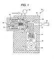
FIG. 1 is a sectional view illustrating the operation of a fuel pump according to the present invention during the suction portion of the pump cycle; -
FIG. 2 is a view similar toFIG. 1 , but illustrating the fuel pump during the initial portion of the compression cycle; -
FIG. 3 is a view similar toFIGS. 1 and2 , but illustrating the fuel pump in the pumping portion of the pumping cycle; -
FIG. 4 is a graph illustrating the coil current versus time for a first embodiment of the invention; -
FIG. 5 is a view similar toFIG. 4 , but illustrating a modification thereof; -
FIG. 6 is a view similar toFIGS. 4 and 5 , but illustrating a further modification thereof; -
FIG. 7 is a view similar toFIGS. 4-6 , but illustrating still a further modification thereof; -
FIG. 8 is a graph illustrating yet a further embodiment of the present invention; -
FIG. 9 is a graph of the coil current versus time for still a further embodiment of the invention; -
FIG. 10 is a view similar toFIG. 9 , but illustrating yet another embodiment of the present invention; -
FIG. 11 is a view illustrating the pulse width versus time of the coil current for still a further embodiment of the present invention; and -
FIG. 12 is a plan view illustrating a modification to the invention. - With reference first to
FIGS. 1-3 , apump 20 for adirect injection engine 22 is illustrated. Thepump 20 includes apump housing 24 which defines apump chamber 26. Thepump chamber 26 is fluidly connected through avalve port 28 to afuel tank 30. Thepump chamber 26 is also fluidly connected to the fuel rail for theengine 22 through acheck valve 32. - A
pump piston 34 is reciprocally mounted within thepump chamber 26. Thispump piston 34 is reciprocally driven by acam 36 typically having three ormore lobes 38. Thecam 36 is mechanically coupled to thepiston 34 by aroller 40 which follows an outer surface of thecam 36. Thisroller 40, furthermore, is maintained in contact with thecam 36 by aspring 42 so that as theengine 22 rotatably drives thecam 36, thecam 36 reciprocally displaces thepiston 34 in thepump chamber 26. - The
fuel pump 20 further includes avalve 50 having a valve head 52 which cooperates with avalve seat 54 which forms thevalve port 28. Anelectric coil 56, upon energization, moves thevalve 50 to an open position in which the valve head 52 is spaced from thevalve seat 54 thus opening theport 28. When in its fully open position, furthermore, thevalve 50 contacts amechanical stop 58 which limits the extension of thevalve 50 in its open position as shown inFIG. 1 . - Conversely, upon deenergization of the
coil 56, aspring 60 and hydraulic force returns thevalve 50 to its closed position, illustrated inFIG. 3 , in which the valve head 52 contacts thevalve seat 54 and closes thefluid port 28. - A
control circuit 62 controls the energization of thecoil 56 to move the coil between its open position, illustrated inFIGS. 1 and2 , and its closed position, illustrated inFIG. 3 . The operation of thecontrol circuit 62 will be subsequently described in greater detail. - In operation, during the suction portion of the pumping cycle, i.e. when the
cam 36 moves thepump piston 34 away from thepump chamber 26, thepump piston 34 inducts fuel from thefuel tank 30 through thefuel port 28 and into thepump chamber 26. During this suction portion of the pumping cycle, the hydraulic pressure caused by the fuel flow from thefuel tank 30 into thepump chamber 26 maintains thevalve 50 in a partially open position. - At some point before the bottommost position of the
pump piston 34, i.e. when the volume of thepump chamber 26 is at a maximum, thecontrol circuit 62 energizes thecoils 56 and moves thevalve 50 to an open position. During low speed engine conditions, i.e. when the engine speed is less than a predetermined threshold, thecontrol circuit 62 maintains thevalve 50 in an open position during the initial portion of the pressurization cycle. During this time, the reciprocation of thepump piston 34 into thepump chamber 26 thus pumps fuel from thepump chamber 26, through thefuel port 28 and back to thefuel tank 30. - At some time prior to the top dead center position of the engine, i.e. where the
pump piston 34 is extended to its maximum amount into thepump chamber 26, thecontrol circuit 62 deenergizes thecoils 56 thus causing thevalve 50 to move to its closed position illustrated inFIG. 3 . When this happens, the increasing pressure within thepump chamber 26 forces thecheck valve 32 to an open position and pumps the fuel from thepump chamber 26 to the fuel rail of thedirect injection engine 22. - There are two primary sources of noise from the fuel pump during low speed engine operation. First, the energization of the
coils 56 and the movement of thevalve 50 to its open position causes thevalve 50 to impact against itsmechanical stop 58 and cause a ticking sound. Similarly, as thevalve 70 is moved to its closed position, such as illustrated inFIG. 3 , the impact of the valve head 52 against thevalve seat 54 also causes noise which is audible at low engine operating conditions. - With reference now to
FIG. 4 , during low engine speed conditions, i.e. when the engine speed is less than a predetermined threshold and the engine fuel requirements are relatively low, theengine control circuit 62 energizes thecoil 56 and holds thevalve 50 open over multiple pumping cycles 72, i.e. wherein each pumping cycle represents one complete reciprocation of thepump piston 34 in thepump housing 24. Thus, as shown inFIG. 4 , agraph 70 of the pump current is illustrated through numerous pump cycles 72. Since the valve is moved to its open position only once over multiple pump cycles and thus causes contact between thevalve 50 and itsmechanical stop 58 only once over multiple cycles, the audible noise from such valve opening and closing (and pressurization) is reduced. Furthermore, even though thepump 20 provides less fuel pressure to theengine 22 since thevalve 50 is held in its open position, such reduced fuel pumping capacity from thefuel pump 20 is acceptable due to the reduced fuel demands of theengine 22 at low speeds. - With reference now to
FIG. 5 , holding thefuel valve 50 open by energizing thecoil 56 over a plurality of pumping cycles may cause undesirable or unacceptable heating of thecoil 56. To prevent such overheating thecontrol circuit 62 reduces the current flow to thecoil 56 during the suction portion of each pumping cycle. Thus,FIG. 5 illustrates agraph 74 of the current to thecoils 56 and in which the current is reduced during the suction portion of each pumping cycle as shown at 76. Thevalve 50, however, remains fully opened during the suction portion of the pumping cycle due to the co-operating hydraulic pressure caused by the fuel inflow into the pumpingchamber 26 during the suction portion of each pumping cycle. - With reference now to
FIG. 6 , a still further alternative is shown in which thecontrol circuit 62 deenergizes thecoil 56 after a certain maximum amount of time as shown at 80 ingraph 78. Such deenergization of the coils is illustrated at 80 inFIG. 6 and such deenergization protects thecoils 56 from overheating. - With reference now to
FIG. 7 , a still further modification is shown of the current control by thecontrol circuit 62 for thecoils 56. InFIG. 7 , agraph 82 of the current flow for thecoil 56 is shown in which the current flow is reduced during each suction portion of the pumping cycle in a fashion similar toFIG. 5 . However, unlikeFIG. 5 , thecontrol circuit 62 also deenergizes thecoils 56 after a certain maximum time period in a fashion similar to that illustrated inFIG. 6 . Consequently, although thegraph 82 of current flow inFIG. 7 shows a reduction in the current flow during each suction portion of the pumping cycle, a larger reduction of the current flow, i.e. a current to zero, also occurs after each maximum time period as shown at 84. - Regardless of which of the strategies illustrated in
FIGS. 4-7 is employed, the overall number of impacts between thevalve 50 and itsmechanical stop 58 or between the valve head 52 and thevalve seat 54 is reduced thus reducing the overall noise from the fuel pump during low speed engine operating conditions. - With reference now to
FIG. 8 , a still further strategy is illustrated for the control of the energization of thecoil 56 by thecontrol circuit 62. The movement of the valve is shown bygraph 90 in which thevalve 50 moves from a closed position, illustrated atposition 92, to a partially open position, illustrated at 94, during the intake portion of the pump cycle. This partial opening of thevalve 50 is caused by the hydraulic pressure of the incoming fuel flow to thepump chamber 26 during the suction cycle. - After the valve is opened to its maximum partially open position due to the hydraulic pressure, the
control circuit 62 energizes thecoils 56 attime 96 thus causing thevalve 50 to move to its fully open position illustrated at 98. However, by timing the energization of thecoils 56 to a period after thevalve 50 is moved to its maximum partially open position due to hydraulic pressure at low engine speeds, the speed of impact of thevalve 70 against itsmechanical stop 58, and thus the noise from the fuel pump, is reduced. - With reference now to
FIG. 9 , a still further strategy to reduce fuel pump noise at low engine speed is illustrated as agraph 100 of the coil current as a function of time. As shown inFIG. 9 , thecontrol circuit 62 utilizes aramp function 102 to energize the coil and move thevalve 50 to its open position. Theramp 102 thus effectively reduces the speed of impact of thevalve 50 against itsmechanical stop 58 at low engine speeds and thus reduces the pump noise. - Similarly, with reference to
FIG. 10 , thecontrol circuit 62 also optionally deenergizes thecoil 56 from its fully energized position, illustrated at 104, into a deenergized condition illustrated at 106 through aramp function 108. Thus, by reducing the current to thecoil 56 through theramp function 108 during deenergization of thecoil 56 at low engine speeds, the speed of impact of the valve head 52 against thevalve seat 54 is reduced thus reducing pump noise. - The control circuit preferably energizes the
coil 56 through pulse width modulation of the current. Thus, with reference toFIG. 11 , the speed of opening of thevalve 50 at low engine speeds may be controlled by thecontrol circuit 62 by reducing the pulse width of the current signal to thecoil 56 during the initiation of the valve opening as shown ingraph 110. By reducing the initial pulse width of the current to thecoil 56, thecontrol circuit 62 reduces the speed of impact, and thus the noise, of thevalve 50 against itsmechanical stop 58. Conversely, the pulse width can be progressively stepped down curing solenoid valve closing to reduce impact of valve head 52 againstvalve seat 54. - With reference now to
FIG. 12 , the fuel noise from the fuel pump, especially fuel noise caused by the fuel suction, may be reduced by varying the lobe design for the pump. More specifically, as illustrated inFIGS. 12 and 13, thecam 36 of thefuel pump 20 includes threelobes pumping piston 34 through one complete pumping cycle. - Although the
lobes lobe 140 is not symmetrical with thelobes lobe 140 reduces pump noise caused by the pump suction. For the strategy where one pressurization stroke is followed by multiple redundant strokes, thelobe 140 provides a slower pressurization rate and hence lower pressurization noise. - From the foregoing it can be seen that the present invention provides a novel pump control for a direct injection internal combustion engine which reduces fuel noise of the type that is evident at low engine speeds. Having described our invention, however, many modifications thereto will become apparent to those skilled in the art to which it pertains without deviation from the spirit of the invention as defined by the scope of the appended claims.
- Features, components and specific details of the structures of the above-described embodiments may be exchanged or combined to form further embodiments optimized for the respective application. As far as those modifications are readily apparent for an expert skilled in the art they shall be disclosed implicitly by the above description without specifying explicitly every possible combination, for the sake of conciseness of the present description.
Claims (15)
- A fuel pump (20) for a direct injection internal combustion engine (22) comprising:a pump piston (34),a rotatably driven cam (36) having a plurality of lobes (38; 136, 138, 140) with an outer surface of said lobes (38; 136-140) positioned in contact with said pump piston (34) so that, upon rotation of said cam (36), said cam (36) reciprocally drives said pump piston (34),wherein at least one lobe is asymmetrical with respect to the other lobes (38; 136-140).
- The invention as defined in claim 1 wherein said plurality of lobes (38; 136-140) comprises N lobes, and wherein the angle spanned by each lobe is substantially 360/N degrees.
- A fuel pump (20) for a direct injection internal combustion engine (22) comprising:a body (24) having a valve seat (54),a valve (50) having a valve head (52), said valve (50) movably mounted to said body (24) between an open position in which said valve head (52) is spaced from said valve seat (54), and a closed position in which said valve head (52) abuts against said valve seat (54),an electric coil (56) which, upon energization, moves said valve (50) to said open position and, upon deenergization, allows said valve (50) to move to said closed position,a control circuit (62) which controls the energization of said coil (56) to reduce the pump noise during operation of the engine (22).
- The invention as defined in claim 3 wherein said control circuit (62) deenergizes said coil (56) in a ramp function (102; 108) whenever the speed of the engine (22) is less than a predetermined threshold to thereby reduce the speed of closure of said valve head (52) from said open to said closed position.
- The invention as defined in claim 3 or 4 wherein said control circuit (62) maintains the coil (56) energization through a plurality of pressurization cycles of the pump (20) during predetermined engine operating conditions.
- The invention as defined in claim 5 wherein said predetermined engine operating conditions include an engine idling condition.
- The invention as defined in claim 3 or 4 wherein said control circuit (62) maintains said coil (56) energized for a predetermined time period during predetermined engine operating conditions.
- The invention as defined in claim 7 wherein said predetermined engine operating conditions include an engine idling condition.
- The invention as defined in claim 3 or 4 wherein said control circuit (62) maintains the coil (56) energization through a plurality of pressurization cycles of the pump (20) up to a maximum time period during predetermined engine operating conditions.
- The invention as defined in any of claims 3 - 9 wherein said control circuit (62) reduces current to said coil (56) during a pump suction intake portion of at least one pump cycle.
- The invention as defined in claim 3 wherein said control circuit (62) energizes said coil (56) in a ramp function (102; 108) during a pump suction intake portion of at least one pump cycle to thereby reduce the speed of opening of said valve head (52) to said open position.
- The invention as defined in any of claims 3 - 11 wherein said coil (56) is energized by a pulse width modulated control signal and wherein said control circuit (62) reduces the current pulse width of the first current pulse during a valve opening cycle.
- The invention as defined in claim 3 wherein said control circuit (62) energizes said coil (56) at a time when valve opening caused by hydraulic pressure during a fuel intake portion of each pump cycle is at a maximum.
- The invention as defined in any of claims 3 - 13 wherein said control is de-energized by a pulse width modulated control signal wherein said control circuit (62) decreases the pulse width during said de-energization.
- A method for reducing injector noise in a direct injection internal combustion engine (22) comprising the steps of:selectively opening and closing a fuel pump valve (50) by activating and deactivating an electric coil (56),decreasing the rate of deactivation of said coil (56) whenever a speed of the engine (22) is less than a preset threshold.
Applications Claiming Priority (1)
| Application Number | Priority Date | Filing Date | Title |
|---|---|---|---|
| US11/943,087 US7552720B2 (en) | 2007-11-20 | 2007-11-20 | Fuel pump control for a direct injection internal combustion engine |
Publications (2)
| Publication Number | Publication Date |
|---|---|
| EP2063100A2 true EP2063100A2 (en) | 2009-05-27 |
| EP2063100A3 EP2063100A3 (en) | 2009-07-15 |
Family
ID=40427880
Family Applications (1)
| Application Number | Title | Priority Date | Filing Date |
|---|---|---|---|
| EP08019839A Withdrawn EP2063100A3 (en) | 2007-11-20 | 2008-11-13 | Fuel pump control for a direct injection internal combustion engine |
Country Status (3)
| Country | Link |
|---|---|
| US (1) | US7552720B2 (en) |
| EP (1) | EP2063100A3 (en) |
| JP (1) | JP2009127623A (en) |
Cited By (7)
| Publication number | Priority date | Publication date | Assignee | Title |
|---|---|---|---|---|
| EP2363594A2 (en) * | 2010-03-05 | 2011-09-07 | Hitachi Ltd. | Fuel pump |
| ITBO20110183A1 (en) * | 2011-04-07 | 2012-10-08 | Magneti Marelli Spa | SILENCED FUEL PUMP FOR A DIRECT INJECTION SYSTEM |
| WO2015039960A1 (en) * | 2013-09-19 | 2015-03-26 | Robert Bosch Gmbh | Electromagnetically actuated suction valve |
| FR3042230A1 (en) * | 2015-10-13 | 2017-04-14 | Continental Automotive France | NOISE REDUCTION OF AN ISOLATION VALVE OF A FUEL TANK OF AN AUTOMOTIVE VEHICLE. |
| CN110700969A (en) * | 2018-07-10 | 2020-01-17 | 罗伯特·博世有限公司 | Fuel delivery device for cryogenic fuels and method for operating same |
| CN111868370A (en) * | 2018-01-17 | 2020-10-30 | 罗伯特·博世有限公司 | Fuel delivery device for cryogenic fuels |
| DE102022102073A1 (en) | 2022-01-28 | 2023-08-03 | Faurecia Autositze Gmbh | Method of operating a vehicle seat comfort system |
Families Citing this family (31)
| Publication number | Priority date | Publication date | Assignee | Title |
|---|---|---|---|---|
| US8015964B2 (en) * | 2006-10-26 | 2011-09-13 | David Norman Eddy | Selective displacement control of multi-plunger fuel pump |
| WO2008094623A1 (en) * | 2007-01-30 | 2008-08-07 | Cummins Inc. | Fuel pump timing to reduce noise |
| US8001942B2 (en) * | 2007-10-31 | 2011-08-23 | GM Global Technology Operations LLC | High pressure piston pump actuating system using automotive starter system |
| US8091530B2 (en) | 2008-12-08 | 2012-01-10 | Ford Global Technologies, Llc | High pressure fuel pump control for idle tick reduction |
| US8342151B2 (en) * | 2008-12-18 | 2013-01-01 | GM Global Technology Operations LLC | Deactivation of high pressure pump for noise control |
| DE102010027745A1 (en) * | 2010-04-14 | 2011-10-20 | Robert Bosch Gmbh | high pressure pump |
| US8677977B2 (en) * | 2010-04-30 | 2014-03-25 | Denso International America, Inc. | Direct injection pump control strategy for noise reduction |
| US8662056B2 (en) * | 2010-12-30 | 2014-03-04 | Delphi Technologies, Inc. | Fuel pressure control system and method having a variable pull-in time interval based pressure |
| US9309849B2 (en) * | 2011-03-23 | 2016-04-12 | Hitachi, Ltd | Method and apparatus for reducing the number of separately distinguishable noise peaks in a direct injection engine |
| US9879662B2 (en) | 2011-05-17 | 2018-01-30 | Holley Performance Products, Inc. | Inline pump assembly and method |
| US9303607B2 (en) | 2012-02-17 | 2016-04-05 | Ford Global Technologies, Llc | Fuel pump with quiet cam operated suction valve |
| US9989026B2 (en) | 2012-02-17 | 2018-06-05 | Ford Global Technologies, Llc | Fuel pump with quiet rotating suction valve |
| DE102012211798B4 (en) * | 2012-07-06 | 2019-12-05 | Robert Bosch Gmbh | Method for actuating a switching element of a valve device |
| KR101905553B1 (en) * | 2012-10-31 | 2018-11-21 | 현대자동차 주식회사 | Control system and control method of gasoline direct injection engine |
| US9169817B2 (en) | 2012-12-05 | 2015-10-27 | Ford Global Technologies, Llc | Fuel pump with metering valve |
| US9671033B2 (en) | 2012-12-11 | 2017-06-06 | Hitachi, Ltd. | Method and apparatus for controlling a solenoid actuated inlet valve |
| US8985077B2 (en) | 2013-03-08 | 2015-03-24 | Ford Global Technologies, Llc | Valvetrain impact absorber |
| US9284931B2 (en) * | 2013-07-24 | 2016-03-15 | Ford Global Technologies, Llc | Engine fuel pump and method for operation thereof |
| US9303583B2 (en) | 2014-01-14 | 2016-04-05 | Ford Global Technologies, Llc | Robust direct injection fuel pump system |
| US9464590B2 (en) | 2014-04-16 | 2016-10-11 | Fca Us Llc | Variable stroke direct injection fuel pump system |
| US9753443B2 (en) | 2014-04-21 | 2017-09-05 | Synerject Llc | Solenoid systems and methods for detecting length of travel |
| US9997287B2 (en) | 2014-06-06 | 2018-06-12 | Synerject Llc | Electromagnetic solenoids having controlled reluctance |
| CN107076127B (en) | 2014-06-09 | 2019-11-12 | 新尼杰特公司 | Method and apparatus for cooling solenoid coil of solenoid pump |
| US10273945B2 (en) | 2014-07-31 | 2019-04-30 | Cummins Inc. | Mechanical fuel pump deactivation |
| JP6265091B2 (en) * | 2014-09-19 | 2018-01-24 | 株式会社デンソー | High pressure pump control device |
| DE102015217955A1 (en) * | 2014-10-21 | 2016-04-21 | Robert Bosch Gmbh | Device for controlling at least one switchable valve |
| DE102014225982A1 (en) * | 2014-12-16 | 2016-06-16 | Robert Bosch Gmbh | Pump, in particular high-pressure fuel pump |
| JP6197822B2 (en) * | 2015-04-13 | 2017-09-20 | トヨタ自動車株式会社 | Fuel supply device for internal combustion engine |
| JP6569542B2 (en) * | 2016-01-21 | 2019-09-04 | 株式会社デンソー | High pressure pump controller |
| US10851738B2 (en) * | 2018-06-15 | 2020-12-01 | Southwest Research Institute | Internal combustion engine having dedicated EGR cylinder(s) and improved fuel pump system |
| US11401883B2 (en) | 2020-04-03 | 2022-08-02 | Ford Global Technologies, Llc | System and method for direct injection fuel pump control |
Family Cites Families (21)
| Publication number | Priority date | Publication date | Assignee | Title |
|---|---|---|---|---|
| US4643155A (en) * | 1984-10-05 | 1987-02-17 | Olin Corporation | Variable stroke, electronically controlled fuel injection control system |
| JP2861429B2 (en) * | 1991-02-27 | 1999-02-24 | 株式会社デンソー | Accumulation type fuel injection system for diesel engine |
| US5558066A (en) | 1995-02-02 | 1996-09-24 | Cummins Engine Company, Inc. | Fuel system vibration damper |
| FR2765635B1 (en) | 1997-07-07 | 1999-09-03 | Sagem | DIRECT FUEL INJECTION PUMP FOR A CONTROLLED IGNITION ENGINE AND INJECTION SYSTEM COMPRISING SUCH A PUMP |
| JP3562351B2 (en) * | 1998-11-24 | 2004-09-08 | トヨタ自動車株式会社 | Fuel pump control device for internal combustion engine |
| JP2001041128A (en) * | 1999-07-28 | 2001-02-13 | Toyota Motor Corp | High pressure fuel pump |
| JP3539302B2 (en) * | 1999-09-09 | 2004-07-07 | トヨタ自動車株式会社 | Fuel supply device for internal combustion engine |
| JP2001182597A (en) | 1999-12-24 | 2001-07-06 | Hitachi Ltd | High pressure fuel pump controller and in-cylinder injection engine controller |
| JP2001263198A (en) | 2000-03-14 | 2001-09-26 | Bosch Automotive Systems Corp | Fuel pump and fuel supply device using it |
| US6460510B1 (en) | 2000-05-30 | 2002-10-08 | Robert H. Breeden | Pump assembly and method |
| JP2002115623A (en) * | 2000-10-05 | 2002-04-19 | Mitsubishi Electric Corp | Variable discharge fuel supply device |
| ITTO20001228A1 (en) * | 2000-12-29 | 2002-06-29 | Fiat Ricerche | FUEL INJECTION SYSTEM FOR AN INTERNAL COMBUSTION ENGINE. |
| JP4123729B2 (en) * | 2001-03-15 | 2008-07-23 | 株式会社日立製作所 | Control method of fuel supply device |
| JP3884252B2 (en) * | 2001-09-27 | 2007-02-21 | 三菱電機株式会社 | High pressure fuel supply solenoid valve |
| DE10215021A1 (en) * | 2002-04-05 | 2003-10-23 | Bosch Gmbh Robert | Fuel injection device for an internal combustion engine |
| GB0229487D0 (en) * | 2002-12-18 | 2003-01-22 | Delphi Tech Inc | Cam arrangement and fuel pump arrangement incorporating a cam arrangement |
| JP4106663B2 (en) * | 2004-03-26 | 2008-06-25 | 株式会社デンソー | Fuel supply device for internal combustion engine |
| WO2006060545A1 (en) * | 2004-12-03 | 2006-06-08 | Stanadyne Corporation | Reduced noise solenoid controlled fuel pump |
| JP4603867B2 (en) * | 2004-12-07 | 2010-12-22 | 日立オートモティブシステムズ株式会社 | Control device and fuel supply system for variable displacement fuel pump |
| JP4415884B2 (en) * | 2005-03-11 | 2010-02-17 | 株式会社日立製作所 | Electromagnetic drive mechanism, high pressure fuel supply pump with electromagnetic valve mechanism and intake valve operated by electromagnetic drive mechanism, high pressure fuel supply pump with electromagnetic valve mechanism |
| EP1717434A1 (en) * | 2005-04-28 | 2006-11-02 | Delphi Technologies, Inc. | Improvements relating to fuel injection systems |
-
2007
- 2007-11-20 US US11/943,087 patent/US7552720B2/en not_active Expired - Fee Related
-
2008
- 2008-04-17 JP JP2008107805A patent/JP2009127623A/en not_active Withdrawn
- 2008-11-13 EP EP08019839A patent/EP2063100A3/en not_active Withdrawn
Cited By (12)
| Publication number | Priority date | Publication date | Assignee | Title |
|---|---|---|---|---|
| EP2363594A2 (en) * | 2010-03-05 | 2011-09-07 | Hitachi Ltd. | Fuel pump |
| ITBO20110183A1 (en) * | 2011-04-07 | 2012-10-08 | Magneti Marelli Spa | SILENCED FUEL PUMP FOR A DIRECT INJECTION SYSTEM |
| EP2508744A1 (en) * | 2011-04-07 | 2012-10-10 | Magneti Marelli S.p.A. | Silenced fuel pump for a direct injection system |
| CN102734019A (en) * | 2011-04-07 | 2012-10-17 | 马涅蒂-马瑞利公司 | Silenced fuel pump for a direct injection system |
| US8474436B2 (en) | 2011-04-07 | 2013-07-02 | MAGNETI MARELLI S.p.A. | Silenced fuel pump for a direct injection system |
| CN102734019B (en) * | 2011-04-07 | 2015-07-15 | 马涅蒂-马瑞利公司 | Silenced fuel pump for a direct injection system |
| WO2015039960A1 (en) * | 2013-09-19 | 2015-03-26 | Robert Bosch Gmbh | Electromagnetically actuated suction valve |
| FR3042230A1 (en) * | 2015-10-13 | 2017-04-14 | Continental Automotive France | NOISE REDUCTION OF AN ISOLATION VALVE OF A FUEL TANK OF AN AUTOMOTIVE VEHICLE. |
| CN111868370A (en) * | 2018-01-17 | 2020-10-30 | 罗伯特·博世有限公司 | Fuel delivery device for cryogenic fuels |
| CN110700969A (en) * | 2018-07-10 | 2020-01-17 | 罗伯特·博世有限公司 | Fuel delivery device for cryogenic fuels and method for operating same |
| CN110700969B (en) * | 2018-07-10 | 2022-06-28 | 罗伯特·博世有限公司 | Fuel delivery device for cryogenic fuel and method of operating the same |
| DE102022102073A1 (en) | 2022-01-28 | 2023-08-03 | Faurecia Autositze Gmbh | Method of operating a vehicle seat comfort system |
Also Published As
| Publication number | Publication date |
|---|---|
| US20090126688A1 (en) | 2009-05-21 |
| US7552720B2 (en) | 2009-06-30 |
| EP2063100A3 (en) | 2009-07-15 |
| JP2009127623A (en) | 2009-06-11 |
Similar Documents
| Publication | Publication Date | Title |
|---|---|---|
| US7552720B2 (en) | Fuel pump control for a direct injection internal combustion engine | |
| EP2453122B1 (en) | Method and control apparatus for controlling a high-pressure fuel supply pump configured to supply pressurized fuel to an internal combustion engine | |
| US8678779B2 (en) | Fuel pump | |
| KR100373616B1 (en) | High-pressure fuel pump and cam for high-pressure fuel pump | |
| JP4701227B2 (en) | Plunger high pressure fuel pump | |
| JP3842002B2 (en) | Variable discharge fuel supply system | |
| US7198034B2 (en) | Method and system for the direct injection of fuel into an internal combustion engine | |
| JP2690734B2 (en) | Variable discharge high pressure pump | |
| JP2001248517A (en) | Variable discharge fuel supply device | |
| JP2007113462A (en) | High pressure fuel supply system using variable displacement fuel pump | |
| EP2647824A1 (en) | Injection pump systems and methods of operation | |
| US7063073B2 (en) | Method for the direct injection of fuel into an internal combustion engine | |
| JP2639017B2 (en) | Variable discharge high pressure pump and control method thereof | |
| US11401883B2 (en) | System and method for direct injection fuel pump control | |
| JP3800932B2 (en) | High pressure fuel pump | |
| JP5648620B2 (en) | High pressure fuel pump | |
| JPH09222056A (en) | Fuel injection device | |
| JP2754541B2 (en) | Variable discharge high pressure pump | |
| JPWO2005111406A1 (en) | High pressure fuel pump | |
| US20040099246A1 (en) | Fuel injector with multiple control valves | |
| JP3794221B2 (en) | High pressure fuel pump | |
| JP6160514B2 (en) | Fuel pump | |
| JP2015090169A (en) | Solenoid valve | |
| JPH11336635A (en) | Variable discharge high pressure pump | |
| JP2690734C (en) |
Legal Events
| Date | Code | Title | Description |
|---|---|---|---|
| PUAI | Public reference made under article 153(3) epc to a published international application that has entered the european phase |
Free format text: ORIGINAL CODE: 0009012 |
|
| AK | Designated contracting states |
Kind code of ref document: A2 Designated state(s): AT BE BG CH CY CZ DE DK EE ES FI FR GB GR HR HU IE IS IT LI LT LU LV MC MT NL NO PL PT RO SE SI SK TR |
|
| AX | Request for extension of the european patent |
Extension state: AL BA MK RS |
|
| PUAL | Search report despatched |
Free format text: ORIGINAL CODE: 0009013 |
|
| RIN1 | Information on inventor provided before grant (corrected) |
Inventor name: SAIKALIS, GEORGE Inventor name: SHIRAISHI, TAKUYA Inventor name: WATANABE, ATSUSHI Inventor name: MCCUNE, DONALD J. Inventor name: BADARINARAYAN, HARSHA Inventor name: BORG, JONATHAN |
|
| AK | Designated contracting states |
Kind code of ref document: A3 Designated state(s): AT BE BG CH CY CZ DE DK EE ES FI FR GB GR HR HU IE IS IT LI LT LU LV MC MT NL NO PL PT RO SE SI SK TR |
|
| AX | Request for extension of the european patent |
Extension state: AL BA MK RS |
|
| RIN1 | Information on inventor provided before grant (corrected) |
Inventor name: SAIKALIS, GEORGE Inventor name: SHIRAISHI, TAKUYA Inventor name: WATANABE, ATSUSHI Inventor name: MCCURE, DONALD J. Inventor name: BADARINARAYAN, HARSHA Inventor name: BORG, JONATHAN |
|
| 17P | Request for examination filed |
Effective date: 20090806 |
|
| STAA | Information on the status of an ep patent application or granted ep patent |
Free format text: STATUS: THE APPLICATION HAS BEEN WITHDRAWN |
|
| AKX | Designation fees paid |
Designated state(s): AT BE BG CH CY CZ DE DK EE ES FI FR GB GR HR HU IE IS IT LI LT LU LV MC MT NL NO PL PT RO SE SI SK TR |
|
| 18W | Application withdrawn |
Effective date: 20100204 |