EP2063063A2 - Retractable covering for an architectural opening - Google Patents
Retractable covering for an architectural opening Download PDFInfo
- Publication number
- EP2063063A2 EP2063063A2 EP08253603A EP08253603A EP2063063A2 EP 2063063 A2 EP2063063 A2 EP 2063063A2 EP 08253603 A EP08253603 A EP 08253603A EP 08253603 A EP08253603 A EP 08253603A EP 2063063 A2 EP2063063 A2 EP 2063063A2
- Authority
- EP
- European Patent Office
- Prior art keywords
- retraction mechanism
- flexible element
- covering device
- retractable
- plane
- Prior art date
- Legal status (The legal status is an assumption and is not a legal conclusion. Google has not performed a legal analysis and makes no representation as to the accuracy of the status listed.)
- Granted
Links
- 230000007246 mechanism Effects 0.000 claims abstract description 57
- 238000004804 winding Methods 0.000 claims description 8
- 239000000725 suspension Substances 0.000 claims 1
- 150000001875 compounds Chemical class 0.000 description 2
- 230000014509 gene expression Effects 0.000 description 2
- 230000001010 compromised effect Effects 0.000 description 1
- 238000010276 construction Methods 0.000 description 1
- 230000000694 effects Effects 0.000 description 1
- 230000004048 modification Effects 0.000 description 1
- 238000012986 modification Methods 0.000 description 1
- 230000000717 retained effect Effects 0.000 description 1
- 239000000779 smoke Substances 0.000 description 1
Images


Classifications
-
- E—FIXED CONSTRUCTIONS
- E06—DOORS, WINDOWS, SHUTTERS, OR ROLLER BLINDS IN GENERAL; LADDERS
- E06B—FIXED OR MOVABLE CLOSURES FOR OPENINGS IN BUILDINGS, VEHICLES, FENCES OR LIKE ENCLOSURES IN GENERAL, e.g. DOORS, WINDOWS, BLINDS, GATES
- E06B9/00—Screening or protective devices for wall or similar openings, with or without operating or securing mechanisms; Closures of similar construction
- E06B9/24—Screens or other constructions affording protection against light, especially against sunshine; Similar screens for privacy or appearance; Slat blinds
- E06B9/26—Lamellar or like blinds, e.g. venetian blinds
- E06B9/28—Lamellar or like blinds, e.g. venetian blinds with horizontal lamellae, e.g. non-liftable
- E06B9/30—Lamellar or like blinds, e.g. venetian blinds with horizontal lamellae, e.g. non-liftable liftable
- E06B9/32—Operating, guiding, or securing devices therefor
- E06B9/322—Details of operating devices, e.g. pulleys, brakes, spring drums, drives
-
- E—FIXED CONSTRUCTIONS
- E06—DOORS, WINDOWS, SHUTTERS, OR ROLLER BLINDS IN GENERAL; LADDERS
- E06B—FIXED OR MOVABLE CLOSURES FOR OPENINGS IN BUILDINGS, VEHICLES, FENCES OR LIKE ENCLOSURES IN GENERAL, e.g. DOORS, WINDOWS, BLINDS, GATES
- E06B9/00—Screening or protective devices for wall or similar openings, with or without operating or securing mechanisms; Closures of similar construction
- E06B9/24—Screens or other constructions affording protection against light, especially against sunshine; Similar screens for privacy or appearance; Slat blinds
- E06B9/26—Lamellar or like blinds, e.g. venetian blinds
- E06B9/28—Lamellar or like blinds, e.g. venetian blinds with horizontal lamellae, e.g. non-liftable
- E06B9/30—Lamellar or like blinds, e.g. venetian blinds with horizontal lamellae, e.g. non-liftable liftable
- E06B9/303—Lamellar or like blinds, e.g. venetian blinds with horizontal lamellae, e.g. non-liftable liftable with ladder-tape
- E06B9/308—Lamellar or like blinds, e.g. venetian blinds with horizontal lamellae, e.g. non-liftable liftable with ladder-tape with coaxial tilting bar and raising shaft
-
- E—FIXED CONSTRUCTIONS
- E06—DOORS, WINDOWS, SHUTTERS, OR ROLLER BLINDS IN GENERAL; LADDERS
- E06B—FIXED OR MOVABLE CLOSURES FOR OPENINGS IN BUILDINGS, VEHICLES, FENCES OR LIKE ENCLOSURES IN GENERAL, e.g. DOORS, WINDOWS, BLINDS, GATES
- E06B9/00—Screening or protective devices for wall or similar openings, with or without operating or securing mechanisms; Closures of similar construction
- E06B9/24—Screens or other constructions affording protection against light, especially against sunshine; Similar screens for privacy or appearance; Slat blinds
- E06B9/26—Lamellar or like blinds, e.g. venetian blinds
- E06B9/38—Other details
- E06B9/388—Details of bottom or upper slats or their attachment
-
- E—FIXED CONSTRUCTIONS
- E06—DOORS, WINDOWS, SHUTTERS, OR ROLLER BLINDS IN GENERAL; LADDERS
- E06B—FIXED OR MOVABLE CLOSURES FOR OPENINGS IN BUILDINGS, VEHICLES, FENCES OR LIKE ENCLOSURES IN GENERAL, e.g. DOORS, WINDOWS, BLINDS, GATES
- E06B9/00—Screening or protective devices for wall or similar openings, with or without operating or securing mechanisms; Closures of similar construction
- E06B9/24—Screens or other constructions affording protection against light, especially against sunshine; Similar screens for privacy or appearance; Slat blinds
- E06B9/26—Lamellar or like blinds, e.g. venetian blinds
- E06B9/28—Lamellar or like blinds, e.g. venetian blinds with horizontal lamellae, e.g. non-liftable
- E06B9/30—Lamellar or like blinds, e.g. venetian blinds with horizontal lamellae, e.g. non-liftable liftable
- E06B9/32—Operating, guiding, or securing devices therefor
- E06B9/327—Guides for raisable lamellar blinds with horizontal lamellae
Landscapes
- Engineering & Computer Science (AREA)
- Structural Engineering (AREA)
- Architecture (AREA)
- Civil Engineering (AREA)
- Operating, Guiding And Securing Of Roll- Type Closing Members (AREA)
- Blinds (AREA)
Abstract
Description
- The present invention relates to a retractable covering for architectural openings, having primary and secondary retraction mechanisms.
- Architectural coverings with primary and secondary lift mechanisms are known in the art. Such architectural coverings are generally intended for escape openings in building structures. The secondary lift mechanism thereby provides an emergency drive that is preferably automatically activated in emergency situations such as in case of a fire. Such a secondary lift mechanism is known from German patent reference
DE 3238437 , which uses a spring motor to wind a separate lift tape for raising its bottom rail. When the secondary lift mechanism operates the separate lift tape, the regular lift tape of the primary lift mechanism will be gathered in an uncontrolled manner between the slats of the blind. This may inhibit or distort subsequent operation of the primary lift system. European patent referenceEP 1681435 also discloses the use of a spring drive for a secondary lift mechanism. Again the secondary lift mechanism uses lift tapes that are separate from the lift tapes for the primary operating mechanism. This results in a similar drawback of the primary lift tapes of being gathered in an uncontrolled fashion. - Accordingly it is an object of the present invention to overcome or ameliorate at least one of the disadvantages of the prior art. It is also an object of the present invention to provide alternative structures which are less cumbersome in assembly and operation and which moreover can be made relatively inexpensively. Alternatively it is an object of the invention to at least provide the public with a useful choice.
- To this end the invention provides a retractable covering device for architectural openings, that includes a collapsible covering member; a bottom bar, positioned along a first edge of the collapsible covering member; at least one flexible element in engagement with the bottom bar for raising the bottom bar and collapsing the covering member to define a retracted position of the covering; a primary retraction mechanism for retracting a first end of the at least one flexible element; and a secondary retraction mechanism operatively connected with the bottom bar for selectively also retracting the covering member, wherein the secondary retraction mechanism is arranged for retracting a second end of the at least one flexible element. The arrangement of sharing one and the same flexible element between two independent retraction mechanism solves one of the major inconveniences of the prior art.
- One advantageous embodiment of the retractable covering device according to the invention further comprises a head rail on a second edge of the covering member opposite the bottom rail, and wherein both the first and secondary retraction mechanisms are associated with the head rail. This makes for a compact arrangement of the retractable covering device with both retraction mechanisms concentrated on one side of the blind and thereby enabling the bottom rail having the least obtrusive contours. In this regard it is further advantageous when the bottom rail is provided with at least one guide element and wherein the at least one flexible element is looped around the at least one guide element to define a first branch extending from the head rail to the at least one guide element and a second branch extending from the at least one guide element to the head rail and parallel to the first branch of the at least one flexible element. In a further advantageous embodiment of the invention the primary retraction mechanism has a first axis of rotation and the secondary retraction mechanism has a second axis of rotation and the second axis of rotation therein is parallel to the first axis of rotation. Thereby it is further advantageous when a first plane is defined that is common to the first and second axes of rotation, which first plane is perpendicular to a second plane that is common to the head and bottom rails in an extended position of the collapsible covering member. These optional features will make it possible to also fit the retractable covering device according to the invention in spaces into which otherwise only conventional retractable covering device would fit.
- Generally it is also advantageous for the retractable covering device according to the invention when the secondary retraction mechanism includes a spring motor. This type of drive can be pretensioned to provide for a rapid operation in case of an emergency.
- Still further advantageous embodiment will become apparent from the following description and appended claims.
- The invention will now be explained in reference to the accompanying drawings, in which:
-
Figure 1 is a compound perspective, sectioned view of a retractable covering device according to the invention, in which section [A] corresponds to a version using a first type of side guiding and section [B] corresponds to a version using a second type of side guiding; -
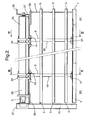
Figure 2 is an elevation of the compound sectioned view ofFigure 1 in the direction of arrows II-II; -
Figure 3 is a cross-sectional view taken along the line III-III inFigure 2 ; and -
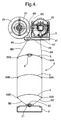
Figure 4 is a cross-sectional view taken along the line IV-IV inFigure 2 . - In
Figure 1 , thereference numerals Figure 1 [A] ) illustrates a Venetian blind 1A, that includes ahead rail 3, a collapsible covering member comprising a plurality ofslats 5 and abottom rail 7. Theslats 5 are each supported by aflexible ladder support 9 as is conventional with Venetian blinds. Theslats 5 of the blind 1A are each guided and retained in vertical alignment by a side guiding arrangement using a rod or tensionedcable 11 extending throughapertures 13 at the longitudinal ends of theslats 5. Similarly, the right hand portion (Figure 1 [B] ) represents a portion or a Venetian blind 1B, having ahead rail 3,slats 5 and abottom rail 7. Theslats 5 are each supported by aflexible ladder support 9 and as such the right hand section of version [B] would be similar to a right-hand portion of the left-hand section of version [A]. The difference is that version [B] has a channel shapedside guide rail 15 in which slat guiding pins (not shown, but conventional) ride along theguide rail 15. Such guiding pins may be attached in theapertures 13 and extend from the longitudinal end of arelevant slat 5. The skilled person will be familiar with the exchangeability of the side guiding details and will easily conceive the execution of the right-hand portion of blind version [A] or the left-hand portion of blind version [B]. Of thelowest slat 5 inFigure 1 , only the contours are shown to reveal more detail of thebottom rail 7. - Also visible in
Figure 1 is that the blind 1A, 1B hasopenings 17 in theslats 5 for the passage offlexible elements 19 for raising thebottom rail 7 and collapsing theslats 5 and ladder supports 9 against thehead rail 3 to retract the Venetian blind 1A, 1B. Thebottom rail 7 is further provided withguide elements 21, which are associated with eachsupport ladder 9 for a purpose to be described herein below. Associated with thehead rail 3 is aprimary retraction mechanism 23 and asecondary retraction mechanism 25. Theprimary retraction mechanism 23 is preferably a conventional motorized mechanism for raising and lowering a window covering that is controlled by a conventional electric switch or remote control unit (not shoiwn). - In
Figure 2 , a rear elevation of the blind ofFigure 1 , the same components are referenced by the same reference numerals. The longitudinal ends of thehead rail 3 are connected with a respectivefirst end bracket 27 andsecond end bracket 29. The first andsecond end brackets head rail 3 and each are adapted to carry one end of thesecondary retraction mechanism 25, which is in the form of a spring motor roller having mounted thereon a first an a second rotatablesecondary winding reel secondary retraction mechanism 25 is arranged in parallel relationship with thehead rail 3. The first andsecond end brackets second mounting flange end bracket anchor strip 39. Also attached to thehead rail 3 are a first pair of spacedarms 41 and a second pair of spacedarms 43. The first and second pair of arms each form a cradle for rotatably supporting a relevant first and second guidingrollers second deflection pins 49, 51 (seeFigures 3 and4 ) for a purpose to be described. -
Figure 3 is a cross-section taken along the line III-III inFigure 2 . Theflexible lift element 19 has afirst branch 19A extending downwardly from theprimary retraction mechanism 23, over the deflection pin 51 (or thesimilar deflection pin 49 as the case may be), towards areturn roller 53 in theguide element 21. Theprimary retraction mechanism 23 is provided with a rotatableprimary winding reel 55 onto, or from, which a first end of theflexible element 19 can be wound or unwound as desired. From the return roller 53 asecond branch 19B of theflexible element 19 extends upwardly to the second guide roller 47 (or thefirst guide roller 45 as the case may be) to have its second end wound by the second secondary winding reel 33 (or firstsecondary winding reel 31 as the case may be). - The reference "P" in
Figures 3 and4 denotes an exemplary guiding pin for use with a side guiding rail (reference "15" as indicated inFigures 1 and2 ).Figure 4 , which is a cross-section along the lines IV-IV ofFigure 2 , shows in more detail one of the ladder supports 9. Eachladder support 9 has afirst branch 9A and asecond branch 9B which both extend from a tilt mechanism associated with theprimary retraction mechanism 23. This tilt mechanism is not shown, but is conventional for combined mono-commando type tilting and lifting mechanisms with which the skilled person is familiar. In the present context a detailed description of such devices is thus deemed redundant. Thefirst branch 9A of theladder support 9 is deflected towards a plane in which theflexible element 19 extends downwardly towards theguide element 21 on thebottom rail 7. Thefirst branch 9A is connected to asecond branch 9B which extends upwardly from theguide element 21 along opposite edges ofslats 5, back to the tilting mechanism associated with theprimary retraction mechanism 23. The interconnected first and second branches enable theladder support 9 to extend through a funnel through theguide element 21 and to effect tilting of the slats without altering the position of thebottom rail 7. The first andsecond branches slats 5 atpoints slats 5 between cross-rungs, extending betweenpoints ladder support 9. Also this system is well known to the skilled person and will not require any further explanation. - The operation of the retractable covering device as described in relation to
Figures 1 to 4 is as follows. Each of the primary andsecondary retraction mechanisms bottom rail 7 by winding a relevant first or second end of theflexible element 19. When theprimary retraction mechanism 23 lifts the bottom rail, it will be lifted with half the speed at which thefirst branch 19A of the flexible element is wound. This will basically reduce the force required to raise a relatively heavy blind, which may be an advantage to the general applicability of theprimary retraction mechanism 23. The further advantage obtained is that there will be no flexible lift element of the secondary retraction mechanism that is compromised or distorted by the lifting action of the primary retraction mechanism. Conversely also thesecondary retraction mechanism 25 may lift thebottom rail 7 through winding of thesecond branch 19B of theflexible element 19 in case of an emergency. Again this action will not compromise or interfere with the operation of theprimary retraction mechanism 23. To achieve this, thesecondary retraction mechanism 25 may be provided with a very strong spring motor which may actually accelerate the movement ofbottom rail 7 towards thehead rail 3. Thereby the flexible covering member formed by theslats 5 and the ladder supports 9 is collapsed between thebottom rail 7 and thehead rail 3. To achieve a quick operation of thesecondary retraction mechanism 25, thehead rail 3 can be provided with an operation device 61 (seeFigure 1 ) that is adapted to withdraw alatch 63 from acircumferential cavity 65 provided in acollar 67 of the secondary retraction mechanism 25 (Figures 1 and4 ). - The
operation device 61 can be remotely controlled by a fire alarm or may be a mechanical device that is responsive to temperature or smoke conditions that can be associated with a fire in a building. Also the operation device can be manually controlled from a button or handle in the close proximity of the escape opening with which the blind is associated. The skilled person will generally be familiar with other suitable mechanisms for withdrawal of thelatch 63 that are both effective and compliant with the applicable regulations. - It is thus believed that the operation and construction of the present invention will be apparent from the foregoing description and accompanying drawing figures. The invention is not limited to any embodiment herein described and, within the purview of the skilled person; modifications are possible which should be considered within the scope of the appended claims. Equally all kinematical inversions are considered inherently disclosed and to be within the scope of the present invention. The term comprising when used in this description or the appended claims should not be construed in an exclusive or exhaustive sense but rather in an inclusive sense. Expressions such as: "means for ..." should be read as: "component configured for ..." or "member constructed to ..." and should be construed to include equivalents for the structures disclosed. The use of expressions like: "critical", "preferred", "especially preferred" etc. is not intended to limit the invention. Features which are not specifically or explicitly described or claimed may be additionally included in the structure according to the present invention without deviating from its scope.
Claims (13)
- Retractable covering device for architectural openings, including:a collapsible covering member;a bottom bar, positioned along a first edge of the collapsible covering member;at least one flexible element in engagement with the bottom bar for raising the bottom bar and collapsing the covering member to define a retracted position of the covering;a primary retraction mechanism for retracting a first end of the at least one flexible element; anda secondary retraction mechanism operatively connected with the bottom bar for selectively also retracting the covering member,wherein the secondary retraction mechanism is arranged for retracting a second end of the at least one flexible element.
- Retractable covering device according to claim 1, wherein the collapsible covering member includes a plurality of elongate slats, kept in a mutually parallel and spaced arrangement by at least two flexible suspension ladders, which are spaced from one another along the length of the slats.
- Retractable covering device according to claim 1 or 2, further comprising a head rail on a second edge of the covering member opposite the bottom rail, and
wherein both the first and secondary retraction mechanisms are associated with the head rail. - Retractable covering device according to claim 3, wherein the bottom rail is provided with at least one guide element and wherein the at least one flexible element is looped around the at least one guide element to define a first branch extending from the head rail to the at least one guide element and a second branch extending from the at least one guide element to the head rail and parallel to the first branch of the at least one flexible element.
- Retractable covering device according to one of claims 1 to 4, wherein the secondary retraction mechanism includes a spring motor.
- Retractable covering device according to one of claims 1 to 5, wherein the at least one flexible element is a lift tape and retraction of the covering member can be accomplished by lifting of the bottom rail.
- Retractable covering device according to one of claims 1 to 6, wherein the primary retraction mechanism includes at least one rotatable primary winding reel to which the first end of the at least one flexible element is attached.
- Retractable covering device according to one of claims 1 to 7, wherein the secondary retraction mechanism includes at least one rotatable secondary winding reel to which the second end of the at least one flexible element is attached.
- Retractable covering device according to one of claims 1 to 8, wherein the primary retraction mechanism has a first axis of rotation and the secondary retraction mechanism has a second axis of rotation and wherein the second axis of rotation is parallel to the first axis of rotation.
- Retractable covering device according to claim 9, wherein a first plane is defined that is common to the first and second axes of rotation, which first plane is perpendicular to a second plane that is common to the head and bottom rails in an extended position of the collapsible covering member.
- Retractable covering device according to claim 10, wherein the at least one flexible element extends in a third plane that intersects the first plane common to the first and second axes of rotation substantially between the first and second axes of rotation.
- Retractable covering device according to claim 11, wherein the third plane is co-extensive with the second plane and wherein the at least one flexible element is deflected from to primary retraction mechanism towards the second plane by a first guide means and from the secondary retraction mechanism towards the second plane by a second guide means.
- Retractable covering device according to claim 12, wherein the first guide means is a deflection pin and wherein the second guide means is a guiding roller.
Priority Applications (1)
| Application Number | Priority Date | Filing Date | Title |
|---|---|---|---|
| EP08253603.8A EP2063063B1 (en) | 2007-11-21 | 2008-11-05 | Retractable covering for an architectural opening |
Applications Claiming Priority (2)
| Application Number | Priority Date | Filing Date | Title |
|---|---|---|---|
| EP07022608 | 2007-11-21 | ||
| EP08253603.8A EP2063063B1 (en) | 2007-11-21 | 2008-11-05 | Retractable covering for an architectural opening |
Publications (3)
| Publication Number | Publication Date |
|---|---|
| EP2063063A2 true EP2063063A2 (en) | 2009-05-27 |
| EP2063063A3 EP2063063A3 (en) | 2013-09-25 |
| EP2063063B1 EP2063063B1 (en) | 2020-02-19 |
Family
ID=40193822
Family Applications (1)
| Application Number | Title | Priority Date | Filing Date |
|---|---|---|---|
| EP08253603.8A Active EP2063063B1 (en) | 2007-11-21 | 2008-11-05 | Retractable covering for an architectural opening |
Country Status (1)
| Country | Link |
|---|---|
| EP (1) | EP2063063B1 (en) |
Citations (2)
| Publication number | Priority date | Publication date | Assignee | Title |
|---|---|---|---|---|
| DE3238473A1 (en) | 1982-10-16 | 1984-04-19 | Ehage Jalousie-Fabrik Erich Hinnenberg GmbH & Co KG, 4006 Erkrath | Venetian blind, in particular for escape doors |
| EP1681435A2 (en) | 2005-01-14 | 2006-07-19 | SCHÜCO International KG | Sun protection system with emergency gathering device |
Family Cites Families (4)
| Publication number | Priority date | Publication date | Assignee | Title |
|---|---|---|---|---|
| US3279528A (en) * | 1962-03-02 | 1966-10-18 | Thomas F Gambon | Shade |
| DE29505849U1 (en) * | 1995-04-11 | 1995-06-01 | Seitz Eugen | Drive device for a roller blind or the like. |
| TW576476U (en) * | 2003-03-17 | 2004-02-11 | Nien Made Entpr Co Ltd | Rolling blind with light penetrating cloth curtains on both front and rear sides |
| DE202006015929U1 (en) * | 2006-10-18 | 2006-12-14 | Guangzhou Carford Decoration Material Co., Ltd. | Roller blind bottom strip with work-saving function has first rail with two supporting regions inside it to form at least one receiving groove and several through holes arranged in one wall of receiving groove |
-
2008
- 2008-11-05 EP EP08253603.8A patent/EP2063063B1/en active Active
Patent Citations (2)
| Publication number | Priority date | Publication date | Assignee | Title |
|---|---|---|---|---|
| DE3238473A1 (en) | 1982-10-16 | 1984-04-19 | Ehage Jalousie-Fabrik Erich Hinnenberg GmbH & Co KG, 4006 Erkrath | Venetian blind, in particular for escape doors |
| EP1681435A2 (en) | 2005-01-14 | 2006-07-19 | SCHÜCO International KG | Sun protection system with emergency gathering device |
Also Published As
| Publication number | Publication date |
|---|---|
| EP2063063B1 (en) | 2020-02-19 |
| EP2063063A3 (en) | 2013-09-25 |
Similar Documents
| Publication | Publication Date | Title |
|---|---|---|
| US4557310A (en) | Movable sun shade system | |
| US9957750B2 (en) | Window covering positional adjustment apparatus | |
| EP2374983B1 (en) | Foldable roller blind | |
| US4799524A (en) | Protection and/or decorative device for apertures in walls, windows and the like | |
| KR101823850B1 (en) | Slatted roller blind | |
| US20040094274A1 (en) | Cordless blind with lock mechanism | |
| US20150275571A1 (en) | Guide arrangement for hangings | |
| EP2031177A2 (en) | Head rail assembly | |
| US8011414B2 (en) | Roll-up shutter with tiltable slots | |
| WO2013074130A1 (en) | Automatic releasable top down shade system and method | |
| JP2003184456A (en) | Operating cord for sun shade member | |
| US20220065040A1 (en) | Semi-rigid chain assembly | |
| EP1904710A1 (en) | Multiple choice shade system | |
| US20160069130A1 (en) | Cordless blind system and retro-fit method | |
| EP2063063B1 (en) | Retractable covering for an architectural opening | |
| KR101098843B1 (en) | Blind device | |
| US20060137830A1 (en) | Winding mechanism of blind | |
| EP0892144B1 (en) | Window blind or shade | |
| KR20180066644A (en) | Roll-Screen Blind Lifting Device | |
| KR101109136B1 (en) | Roll blind | |
| EP2186988B1 (en) | Venetian blind with a mounting device and mounting method | |
| EP0513468A1 (en) | Window covering apparatus | |
| US1266290A (en) | Shade-roller. | |
| CA3178817A1 (en) | Operating device for a window covering | |
| JPH0328713Y2 (en) |
Legal Events
| Date | Code | Title | Description |
|---|---|---|---|
| PUAI | Public reference made under article 153(3) epc to a published international application that has entered the european phase |
Free format text: ORIGINAL CODE: 0009012 |
|
| AK | Designated contracting states |
Kind code of ref document: A2 Designated state(s): AT BE BG CH CY CZ DE DK EE ES FI FR GB GR HR HU IE IS IT LI LT LU LV MC MT NL NO PL PT RO SE SI SK TR |
|
| AX | Request for extension of the european patent |
Extension state: AL BA MK RS |
|
| PUAL | Search report despatched |
Free format text: ORIGINAL CODE: 0009013 |
|
| AK | Designated contracting states |
Kind code of ref document: A3 Designated state(s): AT BE BG CH CY CZ DE DK EE ES FI FR GB GR HR HU IE IS IT LI LT LU LV MC MT NL NO PL PT RO SE SI SK TR |
|
| AX | Request for extension of the european patent |
Extension state: AL BA MK RS |
|
| RIC1 | Information provided on ipc code assigned before grant |
Ipc: E06B 9/388 20060101ALI20130816BHEP Ipc: E06B 9/322 20060101ALI20130816BHEP Ipc: E06B 9/32 20060101AFI20130816BHEP Ipc: E06B 9/327 20060101ALI20130816BHEP Ipc: E06B 9/308 20060101ALI20130816BHEP |
|
| 17P | Request for examination filed |
Effective date: 20140324 |
|
| RBV | Designated contracting states (corrected) |
Designated state(s): AT BE BG CH CY CZ DE DK EE ES FI FR GB GR HR HU IE IS IT LI LT LU LV MC MT NL NO PL PT RO SE SI SK TR |
|
| AKX | Designation fees paid |
Designated state(s): AT BE BG CH CY CZ DE DK EE ES FI FR GB GR HR HU IE IS IT LI LT LU LV MC MT NL NO PL PT RO SE SI SK TR |
|
| 17Q | First examination report despatched |
Effective date: 20160902 |
|
| STAA | Information on the status of an ep patent application or granted ep patent |
Free format text: STATUS: EXAMINATION IS IN PROGRESS |
|
| GRAP | Despatch of communication of intention to grant a patent |
Free format text: ORIGINAL CODE: EPIDOSNIGR1 |
|
| STAA | Information on the status of an ep patent application or granted ep patent |
Free format text: STATUS: GRANT OF PATENT IS INTENDED |
|
| INTG | Intention to grant announced |
Effective date: 20191017 |
|
| GRAS | Grant fee paid |
Free format text: ORIGINAL CODE: EPIDOSNIGR3 |
|
| GRAA | (expected) grant |
Free format text: ORIGINAL CODE: 0009210 |
|
| STAA | Information on the status of an ep patent application or granted ep patent |
Free format text: STATUS: THE PATENT HAS BEEN GRANTED |
|
| AK | Designated contracting states |
Kind code of ref document: B1 Designated state(s): AT BE BG CH CY CZ DE DK EE ES FI FR GB GR HR HU IE IS IT LI LT LU LV MC MT NL NO PL PT RO SE SI SK TR |
|
| REG | Reference to a national code |
Ref country code: GB Ref legal event code: FG4D |
|
| REG | Reference to a national code |
Ref country code: CH Ref legal event code: EP |
|
| REG | Reference to a national code |
Ref country code: DE Ref legal event code: R096 Ref document number: 602008062151 Country of ref document: DE |
|
| REG | Reference to a national code |
Ref country code: AT Ref legal event code: REF Ref document number: 1235156 Country of ref document: AT Kind code of ref document: T Effective date: 20200315 |
|
| REG | Reference to a national code |
Ref country code: IE Ref legal event code: FG4D |
|
| REG | Reference to a national code |
Ref country code: NL Ref legal event code: MP Effective date: 20200219 |
|
| PG25 | Lapsed in a contracting state [announced via postgrant information from national office to epo] |
Ref country code: FI Free format text: LAPSE BECAUSE OF FAILURE TO SUBMIT A TRANSLATION OF THE DESCRIPTION OR TO PAY THE FEE WITHIN THE PRESCRIBED TIME-LIMIT Effective date: 20200219 Ref country code: NO Free format text: LAPSE BECAUSE OF FAILURE TO SUBMIT A TRANSLATION OF THE DESCRIPTION OR TO PAY THE FEE WITHIN THE PRESCRIBED TIME-LIMIT Effective date: 20200519 |
|
| REG | Reference to a national code |
Ref country code: LT Ref legal event code: MG4D |
|
| PG25 | Lapsed in a contracting state [announced via postgrant information from national office to epo] |
Ref country code: HR Free format text: LAPSE BECAUSE OF FAILURE TO SUBMIT A TRANSLATION OF THE DESCRIPTION OR TO PAY THE FEE WITHIN THE PRESCRIBED TIME-LIMIT Effective date: 20200219 Ref country code: LV Free format text: LAPSE BECAUSE OF FAILURE TO SUBMIT A TRANSLATION OF THE DESCRIPTION OR TO PAY THE FEE WITHIN THE PRESCRIBED TIME-LIMIT Effective date: 20200219 Ref country code: SE Free format text: LAPSE BECAUSE OF FAILURE TO SUBMIT A TRANSLATION OF THE DESCRIPTION OR TO PAY THE FEE WITHIN THE PRESCRIBED TIME-LIMIT Effective date: 20200219 Ref country code: BG Free format text: LAPSE BECAUSE OF FAILURE TO SUBMIT A TRANSLATION OF THE DESCRIPTION OR TO PAY THE FEE WITHIN THE PRESCRIBED TIME-LIMIT Effective date: 20200519 Ref country code: GR Free format text: LAPSE BECAUSE OF FAILURE TO SUBMIT A TRANSLATION OF THE DESCRIPTION OR TO PAY THE FEE WITHIN THE PRESCRIBED TIME-LIMIT Effective date: 20200520 Ref country code: IS Free format text: LAPSE BECAUSE OF FAILURE TO SUBMIT A TRANSLATION OF THE DESCRIPTION OR TO PAY THE FEE WITHIN THE PRESCRIBED TIME-LIMIT Effective date: 20200619 |
|
| PG25 | Lapsed in a contracting state [announced via postgrant information from national office to epo] |
Ref country code: NL Free format text: LAPSE BECAUSE OF FAILURE TO SUBMIT A TRANSLATION OF THE DESCRIPTION OR TO PAY THE FEE WITHIN THE PRESCRIBED TIME-LIMIT Effective date: 20200219 |
|
| PG25 | Lapsed in a contracting state [announced via postgrant information from national office to epo] |
Ref country code: LT Free format text: LAPSE BECAUSE OF FAILURE TO SUBMIT A TRANSLATION OF THE DESCRIPTION OR TO PAY THE FEE WITHIN THE PRESCRIBED TIME-LIMIT Effective date: 20200219 Ref country code: EE Free format text: LAPSE BECAUSE OF FAILURE TO SUBMIT A TRANSLATION OF THE DESCRIPTION OR TO PAY THE FEE WITHIN THE PRESCRIBED TIME-LIMIT Effective date: 20200219 Ref country code: CZ Free format text: LAPSE BECAUSE OF FAILURE TO SUBMIT A TRANSLATION OF THE DESCRIPTION OR TO PAY THE FEE WITHIN THE PRESCRIBED TIME-LIMIT Effective date: 20200219 Ref country code: RO Free format text: LAPSE BECAUSE OF FAILURE TO SUBMIT A TRANSLATION OF THE DESCRIPTION OR TO PAY THE FEE WITHIN THE PRESCRIBED TIME-LIMIT Effective date: 20200219 Ref country code: SK Free format text: LAPSE BECAUSE OF FAILURE TO SUBMIT A TRANSLATION OF THE DESCRIPTION OR TO PAY THE FEE WITHIN THE PRESCRIBED TIME-LIMIT Effective date: 20200219 Ref country code: PT Free format text: LAPSE BECAUSE OF FAILURE TO SUBMIT A TRANSLATION OF THE DESCRIPTION OR TO PAY THE FEE WITHIN THE PRESCRIBED TIME-LIMIT Effective date: 20200712 Ref country code: ES Free format text: LAPSE BECAUSE OF FAILURE TO SUBMIT A TRANSLATION OF THE DESCRIPTION OR TO PAY THE FEE WITHIN THE PRESCRIBED TIME-LIMIT Effective date: 20200219 Ref country code: DK Free format text: LAPSE BECAUSE OF FAILURE TO SUBMIT A TRANSLATION OF THE DESCRIPTION OR TO PAY THE FEE WITHIN THE PRESCRIBED TIME-LIMIT Effective date: 20200219 |
|
| REG | Reference to a national code |
Ref country code: DE Ref legal event code: R097 Ref document number: 602008062151 Country of ref document: DE |
|
| PLBE | No opposition filed within time limit |
Free format text: ORIGINAL CODE: 0009261 |
|
| STAA | Information on the status of an ep patent application or granted ep patent |
Free format text: STATUS: NO OPPOSITION FILED WITHIN TIME LIMIT |
|
| REG | Reference to a national code |
Ref country code: AT Ref legal event code: UEP Ref document number: 1235156 Country of ref document: AT Kind code of ref document: T Effective date: 20200219 |
|
| 26N | No opposition filed |
Effective date: 20201120 |
|
| PG25 | Lapsed in a contracting state [announced via postgrant information from national office to epo] |
Ref country code: IT Free format text: LAPSE BECAUSE OF FAILURE TO SUBMIT A TRANSLATION OF THE DESCRIPTION OR TO PAY THE FEE WITHIN THE PRESCRIBED TIME-LIMIT Effective date: 20200219 |
|
| PG25 | Lapsed in a contracting state [announced via postgrant information from national office to epo] |
Ref country code: SI Free format text: LAPSE BECAUSE OF FAILURE TO SUBMIT A TRANSLATION OF THE DESCRIPTION OR TO PAY THE FEE WITHIN THE PRESCRIBED TIME-LIMIT Effective date: 20200219 Ref country code: PL Free format text: LAPSE BECAUSE OF FAILURE TO SUBMIT A TRANSLATION OF THE DESCRIPTION OR TO PAY THE FEE WITHIN THE PRESCRIBED TIME-LIMIT Effective date: 20200219 |
|
| PG25 | Lapsed in a contracting state [announced via postgrant information from national office to epo] |
Ref country code: MC Free format text: LAPSE BECAUSE OF FAILURE TO SUBMIT A TRANSLATION OF THE DESCRIPTION OR TO PAY THE FEE WITHIN THE PRESCRIBED TIME-LIMIT Effective date: 20200219 |
|
| REG | Reference to a national code |
Ref country code: CH Ref legal event code: PL |
|
| GBPC | Gb: european patent ceased through non-payment of renewal fee |
Effective date: 20201105 |
|
| PG25 | Lapsed in a contracting state [announced via postgrant information from national office to epo] |
Ref country code: LU Free format text: LAPSE BECAUSE OF NON-PAYMENT OF DUE FEES Effective date: 20201105 |
|
| REG | Reference to a national code |
Ref country code: BE Ref legal event code: MM Effective date: 20201130 |
|
| PG25 | Lapsed in a contracting state [announced via postgrant information from national office to epo] |
Ref country code: CH Free format text: LAPSE BECAUSE OF NON-PAYMENT OF DUE FEES Effective date: 20201130 Ref country code: LI Free format text: LAPSE BECAUSE OF NON-PAYMENT OF DUE FEES Effective date: 20201130 |
|
| PG25 | Lapsed in a contracting state [announced via postgrant information from national office to epo] |
Ref country code: FR Free format text: LAPSE BECAUSE OF NON-PAYMENT OF DUE FEES Effective date: 20201130 Ref country code: IE Free format text: LAPSE BECAUSE OF NON-PAYMENT OF DUE FEES Effective date: 20201105 |
|
| PG25 | Lapsed in a contracting state [announced via postgrant information from national office to epo] |
Ref country code: GB Free format text: LAPSE BECAUSE OF NON-PAYMENT OF DUE FEES Effective date: 20201105 |
|
| PG25 | Lapsed in a contracting state [announced via postgrant information from national office to epo] |
Ref country code: TR Free format text: LAPSE BECAUSE OF FAILURE TO SUBMIT A TRANSLATION OF THE DESCRIPTION OR TO PAY THE FEE WITHIN THE PRESCRIBED TIME-LIMIT Effective date: 20200219 Ref country code: MT Free format text: LAPSE BECAUSE OF FAILURE TO SUBMIT A TRANSLATION OF THE DESCRIPTION OR TO PAY THE FEE WITHIN THE PRESCRIBED TIME-LIMIT Effective date: 20200219 Ref country code: CY Free format text: LAPSE BECAUSE OF FAILURE TO SUBMIT A TRANSLATION OF THE DESCRIPTION OR TO PAY THE FEE WITHIN THE PRESCRIBED TIME-LIMIT Effective date: 20200219 |
|
| PG25 | Lapsed in a contracting state [announced via postgrant information from national office to epo] |
Ref country code: BE Free format text: LAPSE BECAUSE OF NON-PAYMENT OF DUE FEES Effective date: 20201130 |
|
| PGFP | Annual fee paid to national office [announced via postgrant information from national office to epo] |
Ref country code: AT Payment date: 20221025 Year of fee payment: 15 |
|
| P01 | Opt-out of the competence of the unified patent court (upc) registered |
Effective date: 20230331 |
|
| PGFP | Annual fee paid to national office [announced via postgrant information from national office to epo] |
Ref country code: DE Payment date: 20230929 Year of fee payment: 16 |