EP2062991A1 - Plated steel wire for pws excelling in torsion property and process for producing the same - Google Patents
Plated steel wire for pws excelling in torsion property and process for producing the same Download PDFInfo
- Publication number
- EP2062991A1 EP2062991A1 EP07850344A EP07850344A EP2062991A1 EP 2062991 A1 EP2062991 A1 EP 2062991A1 EP 07850344 A EP07850344 A EP 07850344A EP 07850344 A EP07850344 A EP 07850344A EP 2062991 A1 EP2062991 A1 EP 2062991A1
- Authority
- EP
- European Patent Office
- Prior art keywords
- steel wire
- wire
- wire rod
- area fraction
- pws
- Prior art date
- Legal status (The legal status is an assumption and is not a legal conclusion. Google has not performed a legal analysis and makes no representation as to the accuracy of the status listed.)
- Withdrawn
Links
Images
Classifications
-
- B—PERFORMING OPERATIONS; TRANSPORTING
- B21—MECHANICAL METAL-WORKING WITHOUT ESSENTIALLY REMOVING MATERIAL; PUNCHING METAL
- B21C—MANUFACTURE OF METAL SHEETS, WIRE, RODS, TUBES, PROFILES OR LIKE SEMI-MANUFACTURED PRODUCTS OTHERWISE THAN BY ROLLING; AUXILIARY OPERATIONS USED IN CONNECTION WITH METAL-WORKING WITHOUT ESSENTIALLY REMOVING MATERIAL
- B21C1/00—Manufacture of metal sheets, wire, rods, tubes or like semi-manufactured products by drawing
- B21C1/003—Drawing materials of special alloys so far as the composition of the alloy requires or permits special drawing methods or sequences
-
- C—CHEMISTRY; METALLURGY
- C22—METALLURGY; FERROUS OR NON-FERROUS ALLOYS; TREATMENT OF ALLOYS OR NON-FERROUS METALS
- C22C—ALLOYS
- C22C38/00—Ferrous alloys, e.g. steel alloys
- C22C38/001—Ferrous alloys, e.g. steel alloys containing N
-
- C—CHEMISTRY; METALLURGY
- C22—METALLURGY; FERROUS OR NON-FERROUS ALLOYS; TREATMENT OF ALLOYS OR NON-FERROUS METALS
- C22C—ALLOYS
- C22C38/00—Ferrous alloys, e.g. steel alloys
- C22C38/02—Ferrous alloys, e.g. steel alloys containing silicon
-
- C—CHEMISTRY; METALLURGY
- C22—METALLURGY; FERROUS OR NON-FERROUS ALLOYS; TREATMENT OF ALLOYS OR NON-FERROUS METALS
- C22C—ALLOYS
- C22C38/00—Ferrous alloys, e.g. steel alloys
- C22C38/04—Ferrous alloys, e.g. steel alloys containing manganese
-
- C—CHEMISTRY; METALLURGY
- C22—METALLURGY; FERROUS OR NON-FERROUS ALLOYS; TREATMENT OF ALLOYS OR NON-FERROUS METALS
- C22C—ALLOYS
- C22C38/00—Ferrous alloys, e.g. steel alloys
- C22C38/06—Ferrous alloys, e.g. steel alloys containing aluminium
-
- C—CHEMISTRY; METALLURGY
- C22—METALLURGY; FERROUS OR NON-FERROUS ALLOYS; TREATMENT OF ALLOYS OR NON-FERROUS METALS
- C22C—ALLOYS
- C22C38/00—Ferrous alloys, e.g. steel alloys
- C22C38/14—Ferrous alloys, e.g. steel alloys containing titanium or zirconium
-
- Y—GENERAL TAGGING OF NEW TECHNOLOGICAL DEVELOPMENTS; GENERAL TAGGING OF CROSS-SECTIONAL TECHNOLOGIES SPANNING OVER SEVERAL SECTIONS OF THE IPC; TECHNICAL SUBJECTS COVERED BY FORMER USPC CROSS-REFERENCE ART COLLECTIONS [XRACs] AND DIGESTS
- Y10—TECHNICAL SUBJECTS COVERED BY FORMER USPC
- Y10T—TECHNICAL SUBJECTS COVERED BY FORMER US CLASSIFICATION
- Y10T29/00—Metal working
- Y10T29/49—Method of mechanical manufacture
- Y10T29/4998—Combined manufacture including applying or shaping of fluent material
- Y10T29/49982—Coating
- Y10T29/49986—Subsequent to metal working
-
- Y—GENERAL TAGGING OF NEW TECHNOLOGICAL DEVELOPMENTS; GENERAL TAGGING OF CROSS-SECTIONAL TECHNOLOGIES SPANNING OVER SEVERAL SECTIONS OF THE IPC; TECHNICAL SUBJECTS COVERED BY FORMER USPC CROSS-REFERENCE ART COLLECTIONS [XRACs] AND DIGESTS
- Y10—TECHNICAL SUBJECTS COVERED BY FORMER USPC
- Y10T—TECHNICAL SUBJECTS COVERED BY FORMER US CLASSIFICATION
- Y10T428/00—Stock material or miscellaneous articles
- Y10T428/12—All metal or with adjacent metals
- Y10T428/12493—Composite; i.e., plural, adjacent, spatially distinct metal components [e.g., layers, joint, etc.]
- Y10T428/12771—Transition metal-base component
- Y10T428/12785—Group IIB metal-base component
- Y10T428/12792—Zn-base component
- Y10T428/12799—Next to Fe-base component [e.g., galvanized]
-
- Y—GENERAL TAGGING OF NEW TECHNOLOGICAL DEVELOPMENTS; GENERAL TAGGING OF CROSS-SECTIONAL TECHNOLOGIES SPANNING OVER SEVERAL SECTIONS OF THE IPC; TECHNICAL SUBJECTS COVERED BY FORMER USPC CROSS-REFERENCE ART COLLECTIONS [XRACs] AND DIGESTS
- Y10—TECHNICAL SUBJECTS COVERED BY FORMER USPC
- Y10T—TECHNICAL SUBJECTS COVERED BY FORMER US CLASSIFICATION
- Y10T428/00—Stock material or miscellaneous articles
- Y10T428/29—Coated or structually defined flake, particle, cell, strand, strand portion, rod, filament, macroscopic fiber or mass thereof
- Y10T428/2913—Rod, strand, filament or fiber
-
- Y—GENERAL TAGGING OF NEW TECHNOLOGICAL DEVELOPMENTS; GENERAL TAGGING OF CROSS-SECTIONAL TECHNOLOGIES SPANNING OVER SEVERAL SECTIONS OF THE IPC; TECHNICAL SUBJECTS COVERED BY FORMER USPC CROSS-REFERENCE ART COLLECTIONS [XRACs] AND DIGESTS
- Y10—TECHNICAL SUBJECTS COVERED BY FORMER USPC
- Y10T—TECHNICAL SUBJECTS COVERED BY FORMER US CLASSIFICATION
- Y10T428/00—Stock material or miscellaneous articles
- Y10T428/29—Coated or structually defined flake, particle, cell, strand, strand portion, rod, filament, macroscopic fiber or mass thereof
- Y10T428/2913—Rod, strand, filament or fiber
- Y10T428/2933—Coated or with bond, impregnation or core
- Y10T428/2938—Coating on discrete and individual rods, strands or filaments
-
- Y—GENERAL TAGGING OF NEW TECHNOLOGICAL DEVELOPMENTS; GENERAL TAGGING OF CROSS-SECTIONAL TECHNOLOGIES SPANNING OVER SEVERAL SECTIONS OF THE IPC; TECHNICAL SUBJECTS COVERED BY FORMER USPC CROSS-REFERENCE ART COLLECTIONS [XRACs] AND DIGESTS
- Y10—TECHNICAL SUBJECTS COVERED BY FORMER USPC
- Y10T—TECHNICAL SUBJECTS COVERED BY FORMER US CLASSIFICATION
- Y10T428/00—Stock material or miscellaneous articles
- Y10T428/29—Coated or structually defined flake, particle, cell, strand, strand portion, rod, filament, macroscopic fiber or mass thereof
- Y10T428/2913—Rod, strand, filament or fiber
- Y10T428/2933—Coated or with bond, impregnation or core
- Y10T428/294—Coated or with bond, impregnation or core including metal or compound thereof [excluding glass, ceramic and asbestos]
- Y10T428/2958—Metal or metal compound in coating
Definitions
- the present invention relates to a plated steel wire for PWS that exhibits excellent twist properties and can be used for suspending bridges and the like, and also relates to a method for manufacturing such a plated steel wire.
- hot-rolled wire rods are subjected to a patenting treatment as required, and are then drawn out to form steel wires having a predetermined diameter, and subsequently galvanized to impart corrosion resistance.
- This series of treatments is required to generate a strength of TS ⁇ 2192 - 61 ⁇ d (wherein, TS represents the tensile strength (MPa) and d represents the wire diameter (mm)), and ensure satisfactory ductility performance, which is typically evaluated by the reduction in area at breakage.
- the reduction in area for patented wired rods depends on the grain size of austenite, and the reduction in area can be improved by reducing the grain size of the austenite. Accordingly, attempts have been made to reduce the austenite grain size by using carbides or nitrides ofNb, Ti or B or the like as pinning particles.
- a wire rod has been proposed in which one or more elements selected from the group consisting of 0.01 to 0.1% by weight ofNb, 0.05 to 0.1% by weight of Zr, and 0.02 to 0.5% by weight of Mo are added as constituent elements to a high carbon wire rod (for example, see Patent Document 1).
- the present invention has been made in view of the above circumstances, and has an object of providing a plated steel wire that is inexpensive, can be manufactured with a high yield, and exhibits a high reduction in area and excellent twist properties, and also providing a method for manufacturing such a plated steel wire.
- the inventors of the present invention discovered that by ensuring the existence, within the austenite prior to patenting treatment, of solid-solubilized B in a quantity corresponding with the quantities of C and Si, the driving forces for cementite precipitation and ferrite precipitation could be balanced, and a high carbon pearlite wire rod having a high reduction in area and minimal non-pearlite structures could be obtained, thereby achieving a combination of a high degree of strength and excellent workability due to superior drawability, and they were therefore able to complete the present invention.
- a plated steel wire for PWS with excellent twist properties includes, in terms of mass %: 0.8 to 1.1% of C, 0.8 to 1.3% of Si, 0.3 to 0.8% of Mn, 0.001 to 0.006% of N, and 0.0004 to 0.0060% of B, where a quantity of solid-solubilized B is at least 0.0002%, and also includes either one or both of 0.005 to 0.1% of Al and 0.005 to 0.1% of Ti, and contains as the remainder, Fe and unavoidable impurities, wherein an area fraction of non-pearlite structures in a region from a surface layer down to a depth of 50 ⁇ m is not more than 10%, an area fraction of non-pearlite structures within an entire cross-section is not more than 5%, and a surface of the steel wire is galvanized with a plating quantity within a range from 300 to 500 g/m 2 .
- the plated steel wire for PWS with excellent twist properties according to the present invention may also include, in terms of mass %, one or more elements selected from the group consisting of more than 0% but not more than 0.5% of Cr, more than 0% but not more than 0.5% ofNi, more than 0% but not more than 0.5% of Co, more than 0% but not more than 0.5% of V, more than 0% but not more than 0.2% of Cu, more than 0% but not more than 0.2% of Mo, more than 0% but not more than 0.2% of W, more than 0% but not more than 0.1 % ofNb, and more than 0% but not more than 0.05% of Zr.
- elements selected from the group consisting of more than 0% but not more than 0.5% of Cr, more than 0% but not more than 0.5% ofNi, more than 0% but not more than 0.5% of Co, more than 0% but not more than 0.5% of V, more than 0% but not more than 0.2% of Cu, more than 0% but not more than 0.2% of Mo, more than
- the plated steel wire may also have a wire diameter within a range from 4.5 to 7.5 mm, and a tensile strength that satisfies: TS ⁇ 2192 - 61 ⁇ d (wherein, TS represents the tensile strength (MPa) and d represents the wire diameter (mm)).
- a first aspect of a method for manufacturing a plated steel wire for PWS with excellent twist properties according to the present invention includes: heating, in a furnace
- a slab including, in terms of mass %, 0.8 to 1.1% of C, 0.8 to 1.3% of Si, 0.3 to 0.8% of Mn, 0.001 to 0.006% of N, and 0.0004 to 0.0060% ofB, further including either one or both of 0.005 to 0.1 % of Al and 0.005 to 0.1% of Ti, and containing as the remainder, Fe and unavoidable impurities, subjecting the slab to descaling immediately after extraction from the furnace, and then subjecting the slab to rough rolling and finish rolling, thereby forming a wire rod having a diameter of 9 to 16 mm; cooling the wire rod at a final rolling stand after completion of rolling, and then coiling the wire rod at a rod temperature within a range from 800 to 950°C; subsequently, within a time t1 (seconds) represented by a formula shown below passes, immersing the wire rod in a molten salt at a temperature within a range from 525 to 600°C so as to effect a patent
- Tr is a coiling temperature for the wire rod
- t1 40 seconds if either (N - Ti/3.41 - B + 0.0003) is zero or less, or if a calculated value of t1 exceeds 40 seconds
- ⁇ 2 ⁇ ln d 0 / d
- d 0 represents a diameter (mm) of the wire rod prior to cold working
- d represents a diameter (mm) of the steel wire after cold working
- In represents a natural logarithm
- a temperature of the wire rod may be initially cooled to a temperature of not more than 200°C using a molten salt, Stelmor cooling, or atmospheric cooling, and after completion of a transformation, the wire rod may be reheated to a temperature of at least 950°C to austenitize, and may be then immersed in molten lead at 525 to 600°C so as to effect a patenting treatment.
- a second aspect of a method for manufacturing a plated steel wire for PWS with excellent twist properties includes: performing cold working at a true strain, represented by a formula (3) shown below, of 1.2 to 1.9 on a wire rod including, in terms of mass %, 0.8 to 1.1% of C, 0.8 to 1.3% of Si, 0.3 to 0.8% of Mn, 0.001 to 0.006% of N, and 0.0004 to 0,0060% of B, where a quantity of solid-solubilized B is at least 0.0002%, further including either one or both of 0.005 to 0.1 % of A1 and 0.005 to 0.1% of Ti, and containing as the remainder, Fe and unavoidable impurities, in which an area fraction of non-pearlite structures in a region from a surface layer down to a depth of 100 ⁇ m is not more than 10%, an area fraction of non-pearlite structures within an entire cross-section is not more than 5%, and a tensile strength is at least 1,250 MPa,
- the cold working used for processing the wire rod into steel wire includes not only common wire drawing processes using hole dies, but also cold rolling processes using roller dies.
- excellent twist properties means that when a twist test is conducted on the steel wire or plated steel wire, breakages caused by "localized twisting” in which the twisting is concentrated within a specific location, and “delamination” in which longitudinal cracking occurs after commencement of twisting do not occur.
- the steel wire contains, in terms of mass %, 0.8 to 1.1% of C, 0.8 to 1.3% of Si, 0.3 to 0.8% of Mn, 0.001 to 0.006% ofN, and 0.0004 to 0.0060% ofB, where the quantity of solid-solubilized B is at least 0.0002%, further contains either one or both of 0.005 to 0.1% of Al and 0.005 to 0.05% of Ti, and contains as the remainder, Fe and unavoidable impurities, and the tensile strength TS of the wire satisfies: TS ⁇ 2192 - 61 ⁇ d (wherein, TS represents the tensile strength (MPa) and d represents the wire diameter (mm)).
- the area fraction of non-pearlite structures including proeutectoid ferrites, degenerate pearlite, and bainite that tend to precipitate at the prior austenite grain boundaries is not more than 10% in the region from the surface layer down to a depth of 100 ⁇ m, or the area fraction of non-pearlite structures is not more than 5% in the entire cross-section from the surface layer through to the center of the wire rod, and the remainder of the wire rod is composed of pearlite structures.
- the area fraction of non-pearlite structures including proeutectoid ferrites, degenerate pearlite, and bainite that tend to precipitate at the prior austenite grain boundaries is not more than 10% in the region from the surface layer down to a depth of 50 ⁇ m, or the area fraction of non-pearlite structures is not more than 5% in the entire cross-section from the surface layer through to the center of the steel wire, and the remainder of the steel wire is composed of pearlite structures.
- the plated steel wire still exhibits excellent twist properties.
- C is an element that is effective in increasing the tensile strength of the wire rod, and enhancing the work-hardening rate during drawing of the wire rod.
- the C content is less than 0.8%, then obtaining a high-strength wire rod with a tensile strength of 1,250 MPa or greater is difficult, and the volume fraction of proeutectoid ferrites that precipitate at the austenite grain boundaries during cooling tends to increase; thereby, it is difficult to obtain a uniform pearlite structure.
- the C content is greater than 1.1%, then a proeutectoid cementite network may precipitate at the austenite grain boundaries during the patenting treatment, causing a dramatic deterioration in the drawing workability, the toughness, and the ductility.
- the C content is restricted to a mass % value in the range from 0.8 to 1.1%.
- Si is an element that is effective in increasing the strength of the wire rod, and is also effective as a deoxidizing agent.
- the Si content is 0.8% or greater, the Si is concentrated at the ferrite/cementite interface during the pearlite transformation, and has the effect of inhibiting dissolution of the lamellar cementite under the temperature conditions employed during the plating treatment, thereby suppressing reductions in the tensile strength and ductility.
- the quantity of added Si content is too high, then precipitation of proeutectoid ferrite is accelerated even in a hypereutectoid steel, and the position of the transformation start nose during isothermal transformation tends to shift to a higher temperature, meaning the upper bainite structure fraction after patenting increases, making it difficult to obtain a uniform pearlite structure.
- the mechanical descaling properties also tend to deteriorate.
- the Si content is restricted to a mass % value in the range from 0.8 to 1.3%.
- Mn is an element that is effective as a deoxidizing and desulfurizing agent. Mn is also effective in improving hardenability and increasing the tensile strength after the patenting treatment. If the Mn content is less than 0.3%, then the above effects may be insufficient to achieve the desired increase in tensile strength. In contrast, if the Mn content is greater than 0.8%, then Mn segregates within the central portion of the wire rod, and because bainites or martensites are generated within this segregated portion, the drawing workability tends to deteriorate. For these reasons, the Mn content is restricted to a mass % value in the range from 0.3 to 0.8%.
- Al is an element that is effective as a deoxidizing agent. Furthermore, Al also has an effect of fixing N by forming nitrides, thereby inhibiting coarsening of the austenite grains and suppressing aging, as well as an effect of increasing the quantity of solid-solubilized B.
- the Al content is less than 0.005%, then the effect of the Al in fixing N is difficult to obtain.
- the Al content is greater than 0.1%, then a large quantity of non-deformable alumina-based non-metallic inclusions are generated, thereby lowering the ductility and drawability of the steel wire. Therefore, it is desirable that the Al content is within the range of 0.005 to 0.1 % by mass.
- a quantity of Ti described below is added, then because Ti also has the effect of fixing N, it is possible to obtain the above effects without adding Al. Accordingly, it is not necessary to specify a lower limit for the Al content, and the Al content may be 0%.
- Ti is an element that is effective as a deoxidizing agent. Furthermore, Ti also has an effect of fixing N by forming nitrides, thereby inhibiting coarsening of the austenite grains and suppressing aging, as well as an effect of increasing the quantity of solid-solubilized B.
- the Ti content is less than 0.005%, then the effect of the Ti in fixing N is difficult to obtain. In contrast, if the Ti content is greater than 0.1 %, then the Ti precipitates within the austenite as coarse Ti carbides, lowering the ductility and drawability of the steel wire. For these reasons, the Ti content is restricted to a mass % value in the range from 0.005 to 0.1%.
- N generates nitrides with Al, Ti and B, and has a function of preventing coarsening of the austenite grains during heating.
- the N content is less than 0.001%, then the above function may not be obtainable. In contrast, if the N content is too high, then the quantity of B nitrides generated increases, and the quantity of solid-solubilized B within the austenite is lowered. For these reasons, the N content is restricted to a mass % value in the range from 0.001 to 0.006%.
- B exists within the austenite as solid-solubilized B, it is concentrated at the grain boundaries, and has the effect of suppressing the precipitation of proeutectoid ferrites and accelerating the precipitation of proeutectoid cementites. Accordingly, by adding B in a quantity determined in accordance with its balance with the quantities of C and Si, it is possible to suppress the generation of proeutectoid ferrite and bainite.
- the B content should also be determined with due consideration of its balance with the quantity ofN during the patenting treatment conducted in the wire rod production stage, in order to ensure a quantity of solid-solubilized B within the austenite that yields the above effects.
- the B content is set within a range from 0.0004 to 0.0060%.
- a high-strength plated steel wire for PWS according to the present invention, by ensuring a quantity of solid-solubilized B within the austenite prior to patenting that is in accordance with the quantities of C and Si, a high carbon pearlite wire rod having minimal non-pearlite structures and a high reduction in area can be obtained, and moreover, after cold working and plating treatment, a steel wire with excellent twist properties can be obtained.
- the quantity of solid-solubilized B must be at least 0.0002%.
- the quantity of the impurities P and S is preferably to 0.02% or less.
- the high-strength plated steel wire for PWS described in the present embodiment includes the above components in its basic composition, but one or more of the following selectively allowable additive elements may also be actively added for the purpose of improving the mechanical properties such as the strength, toughness and ductility.
- Cr is an element that is effective for refining the cementite spacing of pearlite, as well as for improving the tensile strength of the wire rod or the work-hardening rate during drawing.
- Cr is preferably added in a quantity of at least 0.1 %.
- the quantity of added Cr is too large, the transformation end time during patenting may be extended, supercooled structures such as martensites, bainites, and the like may be generated, and the mechanical descaling properties may deteriorate, and consequently the upper limit for the Cr content is set to 0.5%.
- Ni has the effects of increasing the drawing workability and the toughness of the wire rod. In order to ensure satisfactory manifestation of these effects, Ni is preferably added in a quantity of at least 0.1%. In contrast, if Ni is added in excess, then the transformation end time is extended, and consequently the upper limit for the Ni content is set to 0.5%.
- Co is an element that is effective in suppressing the precipitation ofproeutectoid cementites during the patenting treatment.
- Co is preferably added in a quantity of at least 0.1%.
- the upper limit for the Co content is set to 0.5%.
- V is an element which, by forming fine carbonitrides within ferrites, suppresses coarsening of the austenite grain size during heating, and contributes to an increase in the strength of the steel afetr hot rolling.
- V is preferably added in a quantity of at least 0.05%.
- the quantity of carbonitrides generated becomes overly large, and the particle size of the carbonitrides also increases, and consequently the upper limit for the V content is set to 0.5%.
- Cu has the effect of enhancing the corrosion resistance of the steel wire.
- Cu is preferably added in a quantity of at least 0.1%.
- the Cu reacts with S, leading to the segregation of CuS at the austenite grain boundaries, and causing defects in the steel ingots or wire rods generated in the course of the wire rod production process.
- the upper limit for the Cu content is set to 0.2%.
- Mo has the effect of enhancing the corrosion resistance of the steel wire.
- Mo is preferably added in a quantity of at least 0.1%.
- the transformation end time tends to be extended, and consequently the upper limit for the Mo content is set to 0.2%.
- W has the effect of enhancing the corrosion resistance of the steel wire.
- W is preferably added in a quantity of at least 0.1%.
- the transformation end time tends to be extended, and consequently the upper limit for the W content is set to 0.2%.
- Nb generates carbonitrides in a similar manner to Ti, thereby having the effect of inhibiting coarsening of the austenite grains during heating.
- Nb is preferably added in a quantity of at least 0.05%.
- the transformation end time tends to be extended, and consequently the upper limit for the Nb content is set to 0.1%.
- Zr generates carbonitrides in a similar manner to Ti, thereby having the effect of inhibiting coarsening of the austenite grains during heating, and also has the effect of enhancing the corrosion resistance.
- Zr is preferably added in a quantity of at least 0.001%.
- the transformation end time tends to be extended, and consequently the upper limit for the Zr content is set to 0.05%.
- One factor that affects the occurrence of delamination in the high-strength plated steel wire is the occurrence of non-pearlite structures, including bainites that are generated along prior austenite grain boundaries of the wire rod, as well as grain boundary ferrites and degenerate pearlites.
- the surface layer acts as the origin for delamination
- a wire rod such as that described in the present embodiment, wherein the area fraction of non-pearlite structures in the region from the surface layer down to a depth of 100 ⁇ m is not more than 10%, is able to suppress the occurrence of delamination during drawing and after plating treatment.
- reducing the quantity of non-pearlite structures within the central portion of the wire rod is effective in improving the reduction in area. It has been confirmed that by ensuring that the area fraction of non-pearlite structures for the entire cross-section from the surface layer through to the center of the wire rod is not more than 5%, as is the case in the wire rod of the present embodiment, the reduction in area can be improved.
- a method for manufacturing the wire rod for a high-strength plated steel wire having excellent twist properties is described below.
- a slab (steel billet) containing the steel components described above is heated in a furnace at 1,000°C to 1,200°C, descaling is performed immediately after extraction from the furnace, and rough rolling and finish rolling are then conducted to form a wire rod having a diameter of 9 to 16 mm. After completion of the rolling, cooling is conducted at the final rolling stand, and the wire rod is then coiled at a rod temperature of 800 to 950°C. Subsequently, within the time period t1 (seconds) represented by the formula shown below passes, a patenting treatment is performed by immersing the wire rod in a molten salt at a temperature of 525 to 600°C.
- t ⁇ 1 0.013 ⁇ Tr - 815 2 + 7 ⁇ B - 0 , 003 / N - Ti / 3.41 - B + 0.0003
- the temperature at which the slab is heated has an effect on the state in which each of the added elements exist, and on the decarburization of the slab.
- the heating temperature is preferably at least 1,000°C.
- the heating temperature of the slab exceeds 1,200°C, then decarburization within the surface layer of the slab increases markedly, and consequently the heating temperature is set within a range from 1,000 to 1,200°C.
- the slab is preferably heated at a comparatively low temperature of 1,100°C or lower and then subjected to an aging heat treatment in order to minimize decarburization.
- Tr is the coiling temperature
- the above formula is valid for component ranges in which (N - Ti/3.41 - B + 0.0003) is greater than zero. If this value is zero or less, then there is no particular limit on the holding time. However, in a practical rolling application, it is very unlikely to take longer than 40 seconds from the completion of coiling until the start of the patenting treatment, and therefore the upper limit is set to 40 seconds.
- the coiling temperature Tr for the coiling that is conducted after rolling and water-cooling affects the quantity of solid-solubilized B at the start of patenting.
- the coiling temperature Tr is less than 800°C, then B carbides tend to precipitate, and the effect of the solid-solubilized B in suppressing non-pearlite structures tends to be inadequate.
- the coiling temperature exceeds 950°C, then the ⁇ grain size becomes overly coarse, causing a deterioration in the reduction in area.
- the coiling temperature is typically at least 800°C, preferably at least 850°C, and even more preferably 900°C or higher, but must be not higher than 950°C.
- the patenting treatment of the wire rod is conducted after coiling, either by a patenting method in which the coiled rod is immersed directly in a molten salt or molten lead at a temperature of 525 to 600°C, or by a patenting method in which the coiled rod is initially cooled, is subsequently reheated to a temperature of at least 950°C to effect reaustenitization, and is then immersed in molten lead at 525 to 600°C.
- the patenting temperature for the wire rod affects the structure of the wire rod after the patenting treatment, and the lamellar spacing of the pearlite. If the patenting temperature exceeds 600°C, then pearlite structures with a coarse lamellar spacing are generated, which causes reductions in the tensile strength and toughness. In contrast, for a steel wire with a high Si content such as the plated steel wire according to the present invention, if the patenting treatment is conducted at a temperature of less than 525°C, then the fraction of bainite structures within the material after patenting tends to increase dramatically.
- the temperature of the molten salt or molten lead is preferably set to at least 525°C.
- TS tensile strength (MPa)
- C represents the C content (mass %) within the steel
- Si represents the Si content (mass %) within the steel
- d 0 represents the wire diameter (mm)
- a steel wire is formed in which the area fraction of non-pearlite structures in the region from the surface layer down to a depth of 50 ⁇ m is not more than 10%, and the area fraction of non-pearlite structures within the entire cross-section is not more than 5%.
- galvanizing is performed with a plating quantity within a range from 300 to 500 g/m 2 .
- ⁇ 2 ⁇ ln d 0 / d (wherein, do represents the diameter (mm) of the steel wire rod prior to cold working, d represents the diameter (mm) of the steel wire after cold working, and ln represents a natural logarithm)
- the true strain ⁇ described in the present invention is a parameter that represents the reduction in area from the original diameter, and as the true strain value is increased, the value of TS also increases.
- the true strain is less than 1.2, then localized twisting may occur when a twist test is conducted, and as a result, drawn wire with a true strain of at least 1.2 is preferred.
- the true strain exceeds 1.9, then for that particular steel wire diameter, the reduction in area may decrease and delamination may also occur, and consequently the upper limit for the true strain is set to 1.9.
- the plating quantity affects the corrosion resistance of the plated steel wire, and the larger the plating quantity becomes, the greater the time required to expose the surface of the steel wire, and therefore the greater the corrosion resistance. Satisfactory corrosion resistance is achieved at plating quantities of 300 g/m 2 or greater. On the other hand, if the plating quantity is too large, then detachment can become a problem, and therefore the upper limit for the plating quantity is set to 500 g/m 2 .
- the compositional relationship between the various components is set to the numerical ranges described above, and ensuring the existence, within the austenite prior to patenting treatment, of solid-solubilized B in a quantity corresponding with the quantities of C and Si, the driving forces for cementite precipitation and ferrite precipitation are balanced, and the generation of non-pearlite structures is suppressed.
- the ductility can be improved, and wire breakages during the drawing process can be prevented, meaning the productivity and the yield can be increased during the production of the plated steel wire for PWS.
- a plated steel wire of diameter 4.5 to 7.5 mm which represents the diameter typically used for PWS, can be manufactured, for example, from a wire rod having the predetermined steel components and structures described above, and having a diameter of 9 to 16 mm.
- the wire has a high degree of strength, indicated by a tensile strength that satisfies TS ⁇ 2192 - 61 ⁇ d (wherein, TS represents the tensile strength (MPa) and d represents the wire diameter (mm)), and also exhibits excellent drawing properties, meaning a plated steel wire for PWS with excellent twist properties can be manufactured in a stable manner.
- Tables 1 and 2 and Tables 5 and 6 show the chemical compositions of sample materials, the patenting conditions, and the mechanical properties of the prepared wire rods. These sample materials were hot rolled to generate wire rods of a predetermined diameter, coiled at a predetermined temperature, and then within a predetermined time passes, subjected to either direct molten salt patenting (DLP) or reheated molten lead patenting (LP). Even for examples having the same components, variation in the time elapsed between coiling and the patenting treatment causes a variation in the quantity of B nitride precipitation, meaning the quantity of solid-solubilized B also differs.
- DLP direct molten salt patenting
- LP reheated molten lead patenting
- a drawing process was conducted via a prescribed cooling method until a predetermined wire diameter was obtained, and a molten galvanizing treatment was then performed.
- the molten galvanizing bath temperature was 450°C.
- wire rods, steel wires, and plated steel wires were evaluated using the evaluation methods described below.
- the quantity of solid-solubilized B was determined by conducting a measurement of the patented wire rod using a methylene blue absorption spectroscopic method.
- the fraction of non-pearlite structures was determined by embedding the patented wire rod or the steel wire that had undergone drawing within a resin, grinding the embedded structure, conducting chemical corrosion using picric acid, and then determining the fraction of non-pearlite structures within a cross-section (an L-section) parallel to the longitudinal direction of the wire rod based on SEM observation of the structure.
- the fraction of non-pearlite structures within the surface layer of the rolled wire rod was determined by first cutting and grinding the wire rod so as to expose an L-section in a region from the center of the wire rod to -5% to +5% of the radius.
- SEM structural observation was used to take structure photographs with a magnification of 2000 ⁇ of 5 views of regions within a depth of 100 ⁇ m from the surface and with a width of 100 ⁇ m, image analysis was used to measure the non-pearlite area fraction within each region, and the average value of those measurements was determined as the surface layer non-pearlite area fraction (non-pearlite area fraction within surface layer).
- the fraction of non-pearlite structures within the surface layer of a drawn steel wire was determined by first cutting and grinding the wire rod so as to expose an L-section in a region from the center of the wire rod to -5% to +5% of the radius.
- SEM structural observation was used to take structure photographs with a magnification of 2000 ⁇ of 5 views of regions within a depth of 40 ⁇ m from the surface and with a width of 100 ⁇ m, image analysis was used to measure the non-pearlite area fraction within each region, and the average value of those measurements was determined as the surface layer non-pearlite area fraction (non-pearlite area fraction within surface layer).
- the non-pearlite area fraction through the entire cross-section of the rolled wire rod or steel wire was determined by using SEM structural observation to take structure photographs with a magnification of 2000 ⁇ of 5 views of regions with a depth of 100 ⁇ m and a width of 100 ⁇ m in the central portion (the 1/2D portion, wherein D represents the diameter of the wire rod or steel wire) of a cross-section (L-section) parallel to the longitudinal direction of the wire rod or steel wire. Image analysis was then used to measure the non-pearlite area fraction within each region, and the average value of those measurements was determined as the cross-sectional non-pearlite area fraction (non-pearlite area fraction within entire cross-section).
- Tables 1 and 2 show the compositions and wire rod production conditions for inventive steels (steels of the present invention) and comparative steels labeled No. 1 to No. 16.
- Tables 3 and 4 show a list of the plated steel wire production conditions and the evaluation results. Table 1 No.
- Patenting conditions and properties of wire rods Diameter (mm) Coiling temperature (°C) Time between coiling and immersion (seconds) t1 (seconds) Patenting method Bath temperature (°C) TS (MPa) TS threshold (MPa) Reduction in area (%) Non-pearlite area fraction within surface layer (%) Non-pearlite area fraction within entire cross-section (%) Quantity of solid-solubilized B (%) 1 12 920 16 17.95 DLP 550 1338 1263 41 7.5 3.5 0.0005 2 12 920 16 17.95 DLP 550 1338 1263 41 7.5 3.5 0.0005 3 12 920 16 17.95 LP 560 1325 1263 38 8.6 4.2 0.0003 4 12 920 16 17.95 DP - 1165 1263 46 14.5 6.9 ⁇ 0.0002 5 12 920 16 40 DLP 550 1335 1260 40 4.3 1.8 0.0012 6 12 920 16 40 LP 560 1314 1260 33 5.0 2.3 0.0010 7 12 920 16 40 DP - 11
- each of the wire rods of the samples labeled Nos. 1 to 3, 5, 6, 12, 13, 15 and 16 had a B content that satisfied the range from 0.0004 to 0.0060%, and also satisfied the condition that the time from completing coiling until the start of patenting is not more than t1.
- each of the wire rods had a quantity of solid-solubilized B of at least 0.0002%, had an area fraction of non-pearlite structures in the region from the wire rod surface layer down to a depth of 100 ⁇ m of not more than 10%, and had an area fraction of non-pearlite structures in the entire cross-section of the wire rod of not more than 5%.
- each of the patented materials had a strength that satisfied the formula: TS ⁇ (1000 ⁇ C + 300 ⁇ Si - 10 ⁇ d 0 + 250) (the TS threshold) and was also 1,250 MPa or greater.
- t1 0.0013 ⁇ (Tr - 815) 2 + 7 ⁇ (B - 0.0003)/(N - Ti/3.41 - B + 0.0003).
- Tables 5 and 6 show the compositions and wire rod production conditions for inventive steels and comparative steels labeled No. 17 to No. 35.
- Tables 7 and 8 show a list of the plated steel wire production conditions and the evaluation results.
- Table 5 No Classification Component C Si Mn P S B Al Ti N Cr Ni Co V Cu Mo W Nb Zr 17
- Inventive steel 0.82 1.20 0.70 0.007 0.006 0.0030 0.000 0.010 0.0035 0.20 0.20 - - 0.05 - - - - 18
- Inventive steel 0.92 1.00 0.60 0.006 0.007 0.0022 0.000 0.0
- the samples represented by Nos. 17 to 26 each represent a plated steel wire for PWS of the present invention (an inventive steel) that exhibits excellent twist properties
- the samples represented by Nos. 27 to 30 and 32 to 35 each represent a comparative steel in which the quantity of one of the components is outside the range prescribed in the present invention
- the sample represented by No. 31 is a comparative steel in which the patenting temperature is outside the temperature range prescribed in the present invention.
- each of the wire rods of the samples labeled Nos. 15 to 24 had a B content that satisfied the range from 0.0004 to 0.0060%, and also satisfied the condition that the time from completing coiling until the start of patenting is not more than t1.
- each of the wire rods had a quantity of solid-solubilized B of at least 0.0002%, had an area fraction of non-pearlite structures in the region from the wire rod surface layer down to a depth of 100 ⁇ m of not more than 10%, and had an area fraction of non-pearlite structures in the entire cross-section of the wire rod of not more than 5%.
- each of the patented materials had a strength that satisfied the formula: TS ⁇ (1000 ⁇ C + 300 ⁇ Si - 10 ⁇ d 0 + 250) (the TS threshold) and was also 1,250 MPa or greater.
- the C content was 0.7%, which does not satisfy the quantity prescribed in the present invention, and the tensile strength of the wire rod did not reach 1,250 MPa, and the tensile strength of the plated steel wire did not reach 1,870 MPa.
- t1 0.0013 ⁇ (Tr - 815) 2 + 7 ⁇ (B - 0.0003)/(N - Ti/3.41 - B + 0.0003).
- the patenting temperature was outside the temperature range prescribed in the present invention, and not only could non-pearlite structures not be suppressed, but delamination occurred after drawing, and after the galvanizing treatment.
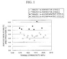
- FIG. 1 is a graph that shows the non-pearlite area fraction within surface layer along the vertical axis, and the tensile strength (MPa) along the horizontal axis, and is used for describing the effect of these factors on delamination occurrence for portions of the plated steel wires used in the examples.
- white circles represent the inventive steels (steels of the present invention) shown in Tables 1 to 4
- white diamonds represent the inventive steels shown in Tables 5 to 8
- black circles represent the comparative steels shown in Tables 1 to 4
- black diamonds represent the comparative steels shown in Tables 5 to 8.
- a wire rod can be obtained in which pearlite structures are predominant, the area fraction of non-pearlite structures in the region from the surface layer down to a depth of 100 ⁇ m is not more than 10%, and the area fraction of non-pearlite structures within the entire cross-section is not more than 5%.
- a plated steel wire for PWS can be manufactured that exhibits excellent twist properties, has a wire diameter within a range from 4.5 to 7.5 mm, and has a tensile strength that satisfies the formula: TS ⁇ 2192 - 61 ⁇ d (wherein, TS represents the tensile strength (MPa) and d represents the wire diameter (mm)).
Landscapes
- Chemical & Material Sciences (AREA)
- Engineering & Computer Science (AREA)
- Mechanical Engineering (AREA)
- Materials Engineering (AREA)
- Metallurgy (AREA)
- Organic Chemistry (AREA)
- Heat Treatment Of Steel (AREA)
- Heat Treatment Of Strip Materials And Filament Materials (AREA)
- Coating With Molten Metal (AREA)
Abstract
Description
- The present invention relates to a plated steel wire for PWS that exhibits excellent twist properties and can be used for suspending bridges and the like, and also relates to a method for manufacturing such a plated steel wire.
- This application claims priority from Japanese Patent Application No.
2007-022412 filed on January 31, 2007 - In a conventional production of high-strength plated steel wire for PWS (parallel wire strand), hot-rolled wire rods are subjected to a patenting treatment as required, and are then drawn out to form steel wires having a predetermined diameter, and subsequently galvanized to impart corrosion resistance. This series of treatments is required to generate a strength of TS ≥ 2192 - 61 × d (wherein, TS represents the tensile strength (MPa) and d represents the wire diameter (mm)), and ensure satisfactory ductility performance, which is typically evaluated by the reduction in area at breakage.
- In order to satisfy the above requirements, attempts have been made to improve the drawing workability of high carbon wire rods, either by controlling segregations or microstructures within the rod material, or by including a specific element within the rod material.
- The reduction in area for patented wired rods depends on the grain size of austenite, and the reduction in area can be improved by reducing the grain size of the austenite. Accordingly, attempts have been made to reduce the austenite grain size by using carbides or nitrides ofNb, Ti or B or the like as pinning particles.
- A wire rod has been proposed in which one or more elements selected from the group consisting of 0.01 to 0.1% by weight ofNb, 0.05 to 0.1% by weight of Zr, and 0.02 to 0.5% by weight of Mo are added as constituent elements to a high carbon wire rod (for example, see Patent Document 1).
- Furthermore, a wire rod in which the austenite grain size is reduced by adding NbC to a high carbon wire rod has also been proposed (for example, see Patent Document 2).
- In the case of the wire rod disclosed in Patent Document 1, the constituent elements described above are added to produce a composition that yields increased ductility for the steel wire. However, in the wire rod disclosed in Patent Document 1, because each of the added constituent elements is expensive, the production costs tend to increase.
- In the wire rod disclosed in Patent Document 2, the drawing workability is improved by adding NbC as pinning particles. However, in the wire rod disclosed in Patent Document 2, because each of the added constituent elements is expensive, the production costs tend to increase. Furthermore, Nb may form coarse carbides or nitrides, and Ti may form coarse oxides, and these may act as the origins of breakages, causing a deterioration in the drawability.
- It has been confirmed that increasing the quantities of C and Si within the wire rod components is the most economical and effective method of increasing the strength of high carbon steel wire. However, as the Si content is increased, ferrite precipitation is accelerated, and cementite precipitation is suppressed. As a result, even in the case of a steel having a hypereutectoid composition with a C content that exceeds 0.8%, when the steel is cooled from the austenite region during the patenting treatment, proeutectoid ferrites tend to precipitate in the form of platelets along the austenite grain boundaries.
- Moreover, because addition of Si causes an increase in the pearlite eutectic temperature, a supercooled composition such as degenerate pearlite or bainite tends to be generated within the temperature range of 480 to 650°C that is typically employed during patenting. As a result, the reduction in area at breakage of the wire rod after patenting treatment tends to decrease, the ductility tends to deteriorate, and the frequency of wire breakages during the drawing process tends to increase, causing a reduction in the productivity and yield.
- Patent Document 1: Japanese Patent No.
2,609,387 - Patent Document 2: Japanese Unexamined Patent Application, First Publication No.
2001-131697 - The present invention has been made in view of the above circumstances, and has an object of providing a plated steel wire that is inexpensive, can be manufactured with a high yield, and exhibits a high reduction in area and excellent twist properties, and also providing a method for manufacturing such a plated steel wire.
- As a result of thorough investigation aimed at achieving the above object, the inventors of the present invention discovered that by ensuring the existence, within the austenite prior to patenting treatment, of solid-solubilized B in a quantity corresponding with the quantities of C and Si, the driving forces for cementite precipitation and ferrite precipitation could be balanced, and a high carbon pearlite wire rod having a high reduction in area and minimal non-pearlite structures could be obtained, thereby achieving a combination of a high degree of strength and excellent workability due to superior drawability, and they were therefore able to complete the present invention.
- Aspects of the present invention are as described below.
- A plated steel wire for PWS with excellent twist properties according to the present invention includes, in terms of mass %: 0.8 to 1.1% of C, 0.8 to 1.3% of Si, 0.3 to 0.8% of Mn, 0.001 to 0.006% of N, and 0.0004 to 0.0060% of B, where a quantity of solid-solubilized B is at least 0.0002%, and also includes either one or both of 0.005 to 0.1% of Al and 0.005 to 0.1% of Ti, and contains as the remainder, Fe and unavoidable impurities, wherein an area fraction of non-pearlite structures in a region from a surface layer down to a depth of 50 µm is not more than 10%, an area fraction of non-pearlite structures within an entire cross-section is not more than 5%, and a surface of the steel wire is galvanized with a plating quantity within a range from 300 to 500 g/m2.
- Further, the plated steel wire for PWS with excellent twist properties according to the present invention may also include, in terms of mass %, one or more elements selected from the group consisting of more than 0% but not more than 0.5% of Cr, more than 0% but not more than 0.5% ofNi, more than 0% but not more than 0.5% of Co, more than 0% but not more than 0.5% of V, more than 0% but not more than 0.2% of Cu, more than 0% but not more than 0.2% of Mo, more than 0% but not more than 0.2% of W, more than 0% but not more than 0.1 % ofNb, and more than 0% but not more than 0.05% of Zr.
- The plated steel wire may also have a wire diameter within a range from 4.5 to 7.5 mm, and a tensile strength that satisfies: TS ≥ 2192 - 61 × d (wherein, TS represents the tensile strength (MPa) and d represents the wire diameter (mm)).
- A first aspect of a method for manufacturing a plated steel wire for PWS with excellent twist properties according to the present invention includes: heating, in a furnace
- at 1,000 to 1,200°C, a slab including, in terms of mass %, 0.8 to 1.1% of C, 0.8 to 1.3% of Si, 0.3 to 0.8% of Mn, 0.001 to 0.006% of N, and 0.0004 to 0.0060% ofB, further including either one or both of 0.005 to 0.1 % of Al and 0.005 to 0.1% of Ti, and containing as the remainder, Fe and unavoidable impurities, subjecting the slab to descaling immediately after extraction from the furnace, and then subjecting the slab to rough rolling and finish rolling, thereby forming a wire rod having a diameter of 9 to 16 mm; cooling the wire rod at a final rolling stand after completion of rolling, and then coiling the wire rod at a rod temperature within a range from 800 to 950°C; subsequently, within a time t1 (seconds) represented by a formula shown below passes, immersing the wire rod in a molten salt at a temperature within a range from 525 to 600°C so as to effect a patenting treatment, and then subjecting a resulting wire rod to cold working at a true strain, represented by a formula (2) shown below, of 1.2 to 1.9, thereby forming a steel wire in which an area fraction of non-pearlite structures in a region from a surface layer down to a depth of 50 µm is not more than 10%, and an area fraction of non-pearlite structures within an entire cross-section is not more than 5%; and subsequently subjecting the steel wire to galvanizing with a plating quantity within a range from 300 to 500 g/m2.

(wherein, in formula (1), Tr is a coiling temperature for the wire rod, and furthermore, t1 = 40 seconds if either (N - Ti/3.41 - B + 0.0003) is zero or less, or if a calculated value of t1 exceeds 40 seconds)
(wherein, in formula (2), d0 represents a diameter (mm) of the wire rod prior to cold working, d represents a diameter (mm) of the steel wire after cold working, and In represents a natural logarithm) - In the above first aspect of a method for manufacturing a plated steel wire for PWS with excellent twist properties according to the present invention, after subjecting the wire rod to rolling and subsequent cooling at the final rolling stand, a temperature of the wire rod may be initially cooled to a temperature of not more than 200°C using a molten salt, Stelmor cooling, or atmospheric cooling, and after completion of a transformation, the wire rod may be reheated to a temperature of at least 950°C to austenitize, and may be then immersed in molten lead at 525 to 600°C so as to effect a patenting treatment.
- A second aspect of a method for manufacturing a plated steel wire for PWS with excellent twist properties according to the present invention includes: performing cold working at a true strain, represented by a formula (3) shown below, of 1.2 to 1.9 on a wire rod including, in terms of mass %, 0.8 to 1.1% of C, 0.8 to 1.3% of Si, 0.3 to 0.8% of Mn, 0.001 to 0.006% of N, and 0.0004 to 0,0060% of B, where a quantity of solid-solubilized B is at least 0.0002%, further including either one or both of 0.005 to 0.1 % of A1 and 0.005 to 0.1% of Ti, and containing as the remainder, Fe and unavoidable impurities, in which an area fraction of non-pearlite structures in a region from a surface layer down to a depth of 100 µm is not more than 10%, an area fraction of non-pearlite structures within an entire cross-section is not more than 5%, and a tensile strength is at least 1,250 MPa, thereby forming a steel wire in which an area fraction of non-pearlite structures in a region from a surface layer down to a depth of 50 µm is not more than 10%, and an area fraction of non-pearlite structures within an entire cross-section is not more than 5%; and subsequently subjecting the steel wire to galvanizing with a plating quantity within a range from 300 to 500 g/m2.

(wherein, in formula (3), do represents a diameter (mm) of the wire rod prior to cold working, d represents a diameter (mm) of the steel wire after cold working, and In represents a natural logarithm). - The cold working used for processing the wire rod into steel wire includes not only common wire drawing processes using hole dies, but also cold rolling processes using roller dies.
- Furthermore, the expression "excellent twist properties" used in the description of the present invention means that when a twist test is conducted on the steel wire or plated steel wire, breakages caused by "localized twisting" in which the twisting is concentrated within a specific location, and "delamination" in which longitudinal cracking occurs after commencement of twisting do not occur.
- In accordance with a plated steel wire for PWS with excellent twist properties and coiling properties according to the present invention, the steel wire contains, in terms of mass %, 0.8 to 1.1% of C, 0.8 to 1.3% of Si, 0.3 to 0.8% of Mn, 0.001 to 0.006% ofN, and 0.0004 to 0.0060% ofB, where the quantity of solid-solubilized B is at least 0.0002%, further contains either one or both of 0.005 to 0.1% of Al and 0.005 to 0.05% of Ti, and contains as the remainder, Fe and unavoidable impurities, and the tensile strength TS of the wire satisfies: TS ≥ 2192 - 61 × d (wherein, TS represents the tensile strength (MPa) and d represents the wire diameter (mm)).
- Furthermore, in the wire rod stage, the area fraction of non-pearlite structures including proeutectoid ferrites, degenerate pearlite, and bainite that tend to precipitate at the prior austenite grain boundaries is not more than 10% in the region from the surface layer down to a depth of 100 µm, or the area fraction of non-pearlite structures is not more than 5% in the entire cross-section from the surface layer through to the center of the wire rod, and the remainder of the wire rod is composed of pearlite structures.
- Moreover, in the steel wire stage after drawing, the area fraction of non-pearlite structures including proeutectoid ferrites, degenerate pearlite, and bainite that tend to precipitate at the prior austenite grain boundaries is not more than 10% in the region from the surface layer down to a depth of 50 µm, or the area fraction of non-pearlite structures is not more than 5% in the entire cross-section from the surface layer through to the center of the steel wire, and the remainder of the steel wire is composed of pearlite structures.
- By setting the quantities of each of the components to the values listed above, and ensuring the existence, within the austenite prior to patenting treatment, of solid-solubilized B in a quantity corresponding with the quantities of C and Si, the driving forces for cementite precipitation and ferrite precipitation are balanced, and the generation of non-pearlite structures can be suppressed. As a result, the ductility can be improved, and wire breakages during the drawing process can be prevented. Therefore, the productivity and the yield can be increased during the production of the plated steel wire for PWS.
- Moreover, even in the case of a plated steel wire prepared by performing a plating treatment on a cold worked steel wire, because the wire contains mainly pearlite, and the area fraction of non-pearlite structures has been reduced, the plated steel wire still exhibits excellent twist properties.
-
-
FIG. 1 is a graph showing the relationship between the surface non-pearlite area fraction and the tensile strength for inventive steels and comparative steels. - A more detailed description of a high-strength plated steel wire for PWS with excellent twist properties according to the present invention, and a method for manufacturing such a plated steel wire is presented below.
- As follows is a description of the reasons for limiting the quantity of each component in a plated steel wire for PWS with excellent twist properties according to the present embodiment.
- C is an element that is effective in increasing the tensile strength of the wire rod, and enhancing the work-hardening rate during drawing of the wire rod.
- If the C content is less than 0.8%, then obtaining a high-strength wire rod with a tensile strength of 1,250 MPa or greater is difficult, and the volume fraction of proeutectoid ferrites that precipitate at the austenite grain boundaries during cooling tends to increase; thereby, it is difficult to obtain a uniform pearlite structure. In contrast, if the C content is greater than 1.1%, then a proeutectoid cementite network may precipitate at the austenite grain boundaries during the patenting treatment, causing a dramatic deterioration in the drawing workability, the toughness, and the ductility. For these reasons, the C content is restricted to a mass % value in the range from 0.8 to 1.1%.
- Si is an element that is effective in increasing the strength of the wire rod, and is also effective as a deoxidizing agent.
- Provided the Si content is 0.8% or greater, the Si is concentrated at the ferrite/cementite interface during the pearlite transformation, and has the effect of inhibiting dissolution of the lamellar cementite under the temperature conditions employed during the plating treatment, thereby suppressing reductions in the tensile strength and ductility. In contrast, if the quantity of added Si content is too high, then precipitation of proeutectoid ferrite is accelerated even in a hypereutectoid steel, and the position of the transformation start nose during isothermal transformation tends to shift to a higher temperature, meaning the upper bainite structure fraction after patenting increases, making it difficult to obtain a uniform pearlite structure. In addition, the mechanical descaling properties also tend to deteriorate. For these reasons, the Si content is restricted to a mass % value in the range from 0.8 to 1.3%.
- Mn is an element that is effective as a deoxidizing and desulfurizing agent. Mn is also effective in improving hardenability and increasing the tensile strength after the patenting treatment. If the Mn content is less than 0.3%, then the above effects may be insufficient to achieve the desired increase in tensile strength. In contrast, if the Mn content is greater than 0.8%, then Mn segregates within the central portion of the wire rod, and because bainites or martensites are generated within this segregated portion, the drawing workability tends to deteriorate. For these reasons, the Mn content is restricted to a mass % value in the range from 0.3 to 0.8%.
- Al is an element that is effective as a deoxidizing agent. Furthermore, Al also has an effect of fixing N by forming nitrides, thereby inhibiting coarsening of the austenite grains and suppressing aging, as well as an effect of increasing the quantity of solid-solubilized B.
- If the Al content is less than 0.005%, then the effect of the Al in fixing N is difficult to obtain. In contrast, if the Al content is greater than 0.1%, then a large quantity of non-deformable alumina-based non-metallic inclusions are generated, thereby lowering the ductility and drawability of the steel wire. Therefore, it is desirable that the Al content is within the range of 0.005 to 0.1 % by mass. However, if a quantity of Ti described below is added, then because Ti also has the effect of fixing N, it is possible to obtain the above effects without adding Al. Accordingly, it is not necessary to specify a lower limit for the Al content, and the Al content may be 0%.
- Ti is an element that is effective as a deoxidizing agent. Furthermore, Ti also has an effect of fixing N by forming nitrides, thereby inhibiting coarsening of the austenite grains and suppressing aging, as well as an effect of increasing the quantity of solid-solubilized B.
- If the Ti content is less than 0.005%, then the effect of the Ti in fixing N is difficult to obtain. In contrast, if the Ti content is greater than 0.1 %, then the Ti precipitates within the austenite as coarse Ti carbides, lowering the ductility and drawability of the steel wire. For these reasons, the Ti content is restricted to a mass % value in the range from 0.005 to 0.1%.
- N generates nitrides with Al, Ti and B, and has a function of preventing coarsening of the austenite grains during heating.
- If the N content is less than 0.001%, then the above function may not be obtainable. In contrast, if the N content is too high, then the quantity of B nitrides generated increases, and the quantity of solid-solubilized B within the austenite is lowered. For these reasons, the N content is restricted to a mass % value in the range from 0.001 to 0.006%.
- When B exists within the austenite as solid-solubilized B, it is concentrated at the grain boundaries, and has the effect of suppressing the precipitation of proeutectoid ferrites and accelerating the precipitation of proeutectoid cementites. Accordingly, by adding B in a quantity determined in accordance with its balance with the quantities of C and Si, it is possible to suppress the generation of proeutectoid ferrite and bainite. On the other hand, because B forms nitrides, the B content should also be determined with due consideration of its balance with the quantity ofN during the patenting treatment conducted in the wire rod production stage, in order to ensure a quantity of solid-solubilized B within the austenite that yields the above effects. If the B content is too high, then not only is the precipitation of proeutectoid cementites accelerated, but there is also the possibility of coarse carbides such as Fe23(C,B)6 being generated within the austenite, causing a deterioration in the drawability. Accordingly, in order to suppress proeutectoid ferrite and bainite, and obtain a wire rod having favorable drawing properties, the B content is set within a range from 0.0004 to 0.0060%.
- In a high-strength plated steel wire for PWS according to the present invention, by ensuring a quantity of solid-solubilized B within the austenite prior to patenting that is in accordance with the quantities of C and Si, a high carbon pearlite wire rod having minimal non-pearlite structures and a high reduction in area can be obtained, and moreover, after cold working and plating treatment, a steel wire with excellent twist properties can be obtained. In order to achieve these effects, the quantity of solid-solubilized B must be at least 0.0002%.
- Although there are no particular restrictions on the quantities of the impurities P and S, the quantity of each is preferably to 0.02% or less.
- The high-strength plated steel wire for PWS described in the present embodiment includes the above components in its basic composition, but one or more of the following selectively allowable additive elements may also be actively added for the purpose of improving the mechanical properties such as the strength, toughness and ductility.
- Cr is an element that is effective for refining the cementite spacing of pearlite, as well as for improving the tensile strength of the wire rod or the work-hardening rate during drawing. In order to ensure satisfactory manifestation of these effects, Cr is preferably added in a quantity of at least 0.1 %. In contrast, if the quantity of added Cr is too large, the transformation end time during patenting may be extended, supercooled structures such as martensites, bainites, and the like may be generated, and the mechanical descaling properties may deteriorate, and consequently the upper limit for the Cr content is set to 0.5%.
- Ni has the effects of increasing the drawing workability and the toughness of the wire rod. In order to ensure satisfactory manifestation of these effects, Ni is preferably added in a quantity of at least 0.1%. In contrast, if Ni is added in excess, then the transformation end time is extended, and consequently the upper limit for the Ni content is set to 0.5%.
- Co is an element that is effective in suppressing the precipitation ofproeutectoid cementites during the patenting treatment. In order to ensure satisfactory manifestation of this effect, Co is preferably added in a quantity of at least 0.1%. In contrast, even if Co is added in excess, the above effect becomes saturated and the production costs become unjustifiable, and consequently the upper limit for the Co content is set to 0.5%.
- V is an element which, by forming fine carbonitrides within ferrites, suppresses coarsening of the austenite grain size during heating, and contributes to an increase in the strength of the steel afetr hot rolling. In order to ensure satisfactory manifestation of this effect, V is preferably added in a quantity of at least 0.05%. In contrast, if V is added in excess, then the quantity of carbonitrides generated becomes overly large, and the particle size of the carbonitrides also increases, and consequently the upper limit for the V content is set to 0.5%.
- Cu has the effect of enhancing the corrosion resistance of the steel wire. In order to ensure satisfactory manifestation of this type of effect, Cu is preferably added in a quantity of at least 0.1%. In contrast, if Cu is added in excess, then the Cu reacts with S, leading to the segregation of CuS at the austenite grain boundaries, and causing defects in the steel ingots or wire rods generated in the course of the wire rod production process. In order to prevent this type of adverse effect, the upper limit for the Cu content is set to 0.2%.
- Mo has the effect of enhancing the corrosion resistance of the steel wire. In order to ensure satisfactory manifestation of this effect, Mo is preferably added in a quantity of at least 0.1%. In contrast, if Mo is added in excess, then the transformation end time tends to be extended, and consequently the upper limit for the Mo content is set to 0.2%.
- W has the effect of enhancing the corrosion resistance of the steel wire. In order to ensure satisfactory manifestation of this effect, W is preferably added in a quantity of at least 0.1%. In contrast, if W is added in excess, then the transformation end time tends to be extended, and consequently the upper limit for the W content is set to 0.2%.
- Nb generates carbonitrides in a similar manner to Ti, thereby having the effect of inhibiting coarsening of the austenite grains during heating. In order to ensure satisfactory manifestation of this effect, Nb is preferably added in a quantity of at least 0.05%. In contrast, ifNb is added in excess, then the transformation end time tends to be extended, and consequently the upper limit for the Nb content is set to 0.1%.
- Zr generates carbonitrides in a similar manner to Ti, thereby having the effect of inhibiting coarsening of the austenite grains during heating, and also has the effect of enhancing the corrosion resistance. In order to ensure satisfactory manifestation of these effects, Zr is preferably added in a quantity of at least 0.001%. In contrast, if Zr is added in excess, then the transformation end time tends to be extended, and consequently the upper limit for the Zr content is set to 0.05%.
- Next is a description of the structure of the wire rod, which for the high-strength plated steel wire with excellent twist properties that represents the target of the present invention is an important factor that affects the level of delamination prevention, the cold workability of the wire rod, and the degree of improvement in the reduction in area.
- One factor that affects the occurrence of delamination in the high-strength plated steel wire is the occurrence of non-pearlite structures, including bainites that are generated along prior austenite grain boundaries of the wire rod, as well as grain boundary ferrites and degenerate pearlites. Moreover, because it is known that the surface layer acts as the origin for delamination, it has been confirmed that a wire rod such as that described in the present embodiment, wherein the area fraction of non-pearlite structures in the region from the surface layer down to a depth of 100 µm is not more than 10%, is able to suppress the occurrence of delamination during drawing and after plating treatment.
- Moreover, reducing the quantity of non-pearlite structures within the central portion of the wire rod is effective in improving the reduction in area. It has been confirmed that by ensuring that the area fraction of non-pearlite structures for the entire cross-section from the surface layer through to the center of the wire rod is not more than 5%, as is the case in the wire rod of the present embodiment, the reduction in area can be improved.
- A method for manufacturing the wire rod for a high-strength plated steel wire having excellent twist properties is described below.
- In this embodiment, a slab (steel billet) containing the steel components described above is heated in a furnace at 1,000°C to 1,200°C, descaling is performed immediately after extraction from the furnace, and rough rolling and finish rolling are then conducted to form a wire rod having a diameter of 9 to 16 mm. After completion of the rolling, cooling is conducted at the final rolling stand, and the wire rod is then coiled at a rod temperature of 800 to 950°C. Subsequently, within the time period t1 (seconds) represented by the formula shown below passes, a patenting treatment is performed by immersing the wire rod in a molten salt at a temperature of 525 to 600°C.

- The temperature at which the slab is heated has an effect on the state in which each of the added elements exist, and on the decarburization of the slab. In order to ensure solid-solubilization of B, the heating temperature is preferably at least 1,000°C. On the other hand, if the heating temperature of the slab exceeds 1,200°C, then decarburization within the surface layer of the slab increases markedly, and consequently the heating temperature is set within a range from 1,000 to 1,200°C. The slab is preferably heated at a comparatively low temperature of 1,100°C or lower and then subjected to an aging heat treatment in order to minimize decarburization.
- In order to obtain a wire rod having the structure and tensile strength prescribed in the present embodiment using a slab having the composition prescribed in the present embodiment, it is necessary to prevent the precipitation of B carbides or nitrides, both during transport of the wire rod from the coiling stage that is conducted after rolling through to the start of the patenting treatment, and during the cooling conducted at the time of the patenting treatment, and moreover, it is also necessary to ensure that the quantity of solid-solubilized B represents a mass % of at least 0.0002%. Based on investigations by the inventors of the present invention, it became evident that when the structure and solid-solubilized B content were measured for a wire rod prepared by heating at 1,050°C, conducting rapid cooling to a temperature of 750 to 950°C within 1 second, holding this temperature for a certain period of time, and then conducting lead patenting, then the holding time limit required to ensure a solid-solubilized B content of at least 0.0002% was a C-shaped curve determined by the combination of the quantities of B and N, and the time limit t1 could be represented by the formula (1) shown below.

- In the above formula (1), Tr is the coiling temperature, and the above formula is valid for component ranges in which (N - Ti/3.41 - B + 0.0003) is greater than zero. If this value is zero or less, then there is no particular limit on the holding time. However, in a practical rolling application, it is very unlikely to take longer than 40 seconds from the completion of coiling until the start of the patenting treatment, and therefore the upper limit is set to 40 seconds.
- The coiling temperature Tr for the coiling that is conducted after rolling and water-cooling affects the quantity of solid-solubilized B at the start of patenting.
- In order to obtain a wire rod having the structure prescribed in the present embodiment, patenting must be started within the time period t1 represented by the above formula (1). If the coiling temperature Tr is less than 800°C, then B carbides tend to precipitate, and the effect of the solid-solubilized B in suppressing non-pearlite structures tends to be inadequate. In contrast, if the coiling temperature exceeds 950°C, then the γ grain size becomes overly coarse, causing a deterioration in the reduction in area. Accordingly, the coiling temperature is typically at least 800°C, preferably at least 850°C, and even more preferably 900°C or higher, but must be not higher than 950°C.
- The patenting treatment of the wire rod is conducted after coiling, either by a patenting method in which the coiled rod is immersed directly in a molten salt or molten lead at a temperature of 525 to 600°C, or by a patenting method in which the coiled rod is initially cooled, is subsequently reheated to a temperature of at least 950°C to effect reaustenitization, and is then immersed in molten lead at 525 to 600°C.
- The patenting temperature for the wire rod affects the structure of the wire rod after the patenting treatment, and the lamellar spacing of the pearlite. If the patenting temperature exceeds 600°C, then pearlite structures with a coarse lamellar spacing are generated, which causes reductions in the tensile strength and toughness. In contrast, for a steel wire with a high Si content such as the plated steel wire according to the present invention, if the patenting treatment is conducted at a temperature of less than 525°C, then the fraction of bainite structures within the material after patenting tends to increase dramatically. Within the region from the surface layer down to a depth of 100 µm, in order to suppress supercooling and restrict the area fraction of non-pearlite structures to not more than 10%, the temperature of the molten salt or molten lead is preferably set to at least 525°C.
- By conducting the patenting treatment in the manner described above, non-pearlite structures within the entire cross-section of the wire rod (the rolled material) can be suppressed to not more than 5%, and a tensile strength TS represented by a formula (4) shown below can be ensured.

(wherein, TS represents the tensile strength (MPa), C represents the C content (mass %) within the steel, Si represents the Si content (mass %) within the steel, and d0 represents the wire diameter (mm)) - As follows is a description of the reasons for restricting the method for manufacturing a plated steel wire for PWS that exhibits excellent toughness, a high degree of strength and excellent twist properties using the wire rod manufactured under the conditions outlined above.
- In the present embodiment, by subjecting the wire rod manufactured under the above conditions to cold working at a true strain, represented by a formula (2) shown below, of 1.2 to 1.9, a steel wire is formed in which the area fraction of non-pearlite structures in the region from the surface layer down to a depth of 50 µm is not more than 10%, and the area fraction of non-pearlite structures within the entire cross-section is not more than 5%. Subsequently, galvanizing is performed with a plating quantity within a range from 300 to 500 g/m2.

(wherein, do represents the diameter (mm) of the steel wire rod prior to cold working, d represents the diameter (mm) of the steel wire after cold working, and ln represents a natural logarithm) - The true strain ε described in the present invention is a parameter that represents the reduction in area from the original diameter, and as the true strain value is increased, the value of TS also increases. However, if the true strain is less than 1.2, then localized twisting may occur when a twist test is conducted, and as a result, drawn wire with a true strain of at least 1.2 is preferred. In contrast, if the true strain exceeds 1.9, then for that particular steel wire diameter, the reduction in area may decrease and delamination may also occur, and consequently the upper limit for the true strain is set to 1.9.
- The plating quantity affects the corrosion resistance of the plated steel wire, and the larger the plating quantity becomes, the greater the time required to expose the surface of the steel wire, and therefore the greater the corrosion resistance. Satisfactory corrosion resistance is achieved at plating quantities of 300 g/m2 or greater. On the other hand, if the plating quantity is too large, then detachment can become a problem, and therefore the upper limit for the plating quantity is set to 500 g/m2.
- As described above, in the present embodiment, by setting the compositional relationship between the various components to the numerical ranges described above, and ensuring the existence, within the austenite prior to patenting treatment, of solid-solubilized B in a quantity corresponding with the quantities of C and Si, the driving forces for cementite precipitation and ferrite precipitation are balanced, and the generation of non-pearlite structures is suppressed. As a result, the ductility can be improved, and wire breakages during the drawing process can be prevented, meaning the productivity and the yield can be increased during the production of the plated steel wire for PWS.
- Further, even in the case of a plated steel wire prepared by performing a plating treatment on a cold worked steel wire, because the wire has a structure containing mainly pearlite, in which the area fraction of non-pearlite structures has been reduced, a plated steel wire for PWS having excellent twist properties can still be obtained.
- Furthermore, in the present embodiment, a plated steel wire of diameter 4.5 to 7.5 mm, which represents the diameter typically used for PWS, can be manufactured, for example, from a wire rod having the predetermined steel components and structures described above, and having a diameter of 9 to 16 mm. Even at this steel wire diameter, because the structure contains mainly pearlite structures, the wire has a high degree of strength, indicated by a tensile strength that satisfies TS ≥ 2192 - 61 × d (wherein, TS represents the tensile strength (MPa) and d represents the wire diameter (mm)), and also exhibits excellent drawing properties, meaning a plated steel wire for PWS with excellent twist properties can be manufactured in a stable manner.
- A more detailed description of the present invention is presented below based on a series of examples, but the present invention is in no way limited by the examples described below, and many modifications can be made within the scope of the present invention, with all of these modifications deemed to fall within the technical scope of the present invention.
- Tables 1 and 2, and Tables 5 and 6 show the chemical compositions of sample materials, the patenting conditions, and the mechanical properties of the prepared wire rods. These sample materials were hot rolled to generate wire rods of a predetermined diameter, coiled at a predetermined temperature, and then within a predetermined time passes, subjected to either direct molten salt patenting (DLP) or reheated molten lead patenting (LP). Even for examples having the same components, variation in the time elapsed between coiling and the patenting treatment causes a variation in the quantity of B nitride precipitation, meaning the quantity of solid-solubilized B also differs.
- Subsequently, using these patented materials, a drawing process was conducted via a prescribed cooling method until a predetermined wire diameter was obtained, and a molten galvanizing treatment was then performed. The molten galvanizing bath temperature was 450°C.
- These wire rods, steel wires, and plated steel wires were evaluated using the evaluation methods described below.
- The quantity of solid-solubilized B was determined by conducting a measurement of the patented wire rod using a methylene blue absorption spectroscopic method.
- The fraction of non-pearlite structures was determined by embedding the patented wire rod or the steel wire that had undergone drawing within a resin, grinding the embedded structure, conducting chemical corrosion using picric acid, and then determining the fraction of non-pearlite structures within a cross-section (an L-section) parallel to the longitudinal direction of the wire rod based on SEM observation of the structure.
- The fraction of non-pearlite structures within the surface layer of the rolled wire rod was determined by first cutting and grinding the wire rod so as to expose an L-section in a region from the center of the wire rod to -5% to +5% of the radius. For the surface layer portion, SEM structural observation was used to take structure photographs with a magnification of 2000× of 5 views of regions within a depth of 100 µm from the surface and with a width of 100 µm, image analysis was used to measure the non-pearlite area fraction within each region, and the average value of those measurements was determined as the surface layer non-pearlite area fraction (non-pearlite area fraction within surface layer).
- The fraction of non-pearlite structures within the surface layer of a drawn steel wire was determined by first cutting and grinding the wire rod so as to expose an L-section in a region from the center of the wire rod to -5% to +5% of the radius. For the surface layer portion, SEM structural observation was used to take structure photographs with a magnification of 2000× of 5 views of regions within a depth of 40 µm from the surface and with a width of 100 µm, image analysis was used to measure the non-pearlite area fraction within each region, and the average value of those measurements was determined as the surface layer non-pearlite area fraction (non-pearlite area fraction within surface layer).
- The non-pearlite area fraction through the entire cross-section of the rolled wire rod or steel wire was determined by using SEM structural observation to take structure photographs with a magnification of 2000× of 5 views of regions with a depth of 100 µm and a width of 100 µm in the central portion (the 1/2D portion, wherein D represents the diameter of the wire rod or steel wire) of a cross-section (L-section) parallel to the longitudinal direction of the wire rod or steel wire. Image analysis was then used to measure the non-pearlite area fraction within each region, and the average value of those measurements was determined as the cross-sectional non-pearlite area fraction (non-pearlite area fraction within entire cross-section).
- These measurements confirmed that the area fraction of non-pearlite structures prior to drawing was substantially equal to the area fraction of non-pearlite structures after drawing.
- When a decarburized layer was present at the surface layer, the totally decarburized portion, as specified in JIS G 0558 (4) was excluded from the measurement.
- The tensile strength TS (MPa) was measured by conducting a tensile test under conditions including a gauge length of 200 mm and a speed of 10 mm/minute, and the average value was determined for n=3 (namely, the measurement was performed three times, and the average value of the measured results was calculated).
- A twist test was conducted under conditions including a gauge length of 100D mm (wherein, D represents the diameter of the steel wire) and a speed of 20 rpm. For n=3 (namely three test repetitions), the number of revolutions until breakage was measured as the twist value, and the average value of these measured twist values was calculated. The occurrence or absence of delamination was determined from a torque pattern measured at the same time as the twist test. Moreover, the existence of localized twisting was determined on the basis of the sample twist test results.
- Tables 1 and 2 show the compositions and wire rod production conditions for inventive steels (steels of the present invention) and comparative steels labeled No. 1 to No. 16. Tables 3 and 4 show a list of the plated steel wire production conditions and the evaluation results.
Table 1 No. Classification Component (mass %) C Si Mn P S B Al Ti N Cr 1 Inventive steel 0.86 0.91 0.76 0.008 0.008 0.0018 0.043 0.000 0.0044 - 2 Inventive steel 0.86 0.91 0.76 0.008 0.008 0.0018 0.043 0.000 0.0044 - 3 Inventive steel 0.86 0.91 0.76 0.008 0.008 0.0018 0.043 0.000 0.0044 - 4 Comparative steel 0.86 0.91 0.76 0.008 0.008 0.0018 0.043 0.000 0.0044 - 5 Inventive steel 0.86 0.90 0.75 0.008 0.006 0.0022 0.043 0.010 0.0040 - 6 Inventive steel 0.86 0.90 0.75 0.008 0.006 0.0022 0.043 0.010 0.0040 - 7 Comparative steel 0.86 0.90 0.75 0.008 0.006 0.0022 0.043 0.010 0.0040 - 8 Comparative steel 0.87 0.90 0.74 0.008 0.008 0.0000 0.041 0.000 0.0043 - 9 Comparative steel 0.87 0.90 0.74 0.008 0.008 0.0000 0.041 0.000 0.0043 - 10 Comparative steel 0.87 0.90 0.74 0.008 0.008 0.0000 0.041 0.000 0.0043 - 11 Comparative steel 0.87 0.90 0.74 0.008 0.008 0.0000 0.041 0.000 0.0043 - 12 Inventive steel 0.87 1.00 0.40 0.008 0.005 0.0020 0.035 0.000 0.0025 0.25 13 Inventive steel 0.87 1.00 0.40 0.008 0.005 0.0020 0.035 0.000 0.0025 0.25 14 Comparative steel 0.87 0.99 0.42 0.008 0.006 0.0000 0.038 0.000 0.0032 0.25 15 Inventive steel 0.87 0.90 0.75 0.007 0.006 0.0012 0.030 0.012 0.0035 - 16 Inventive steel 0.87 0.90 0.75 0.007 0.006 0.0012 0.030 0.012 0.0035 - Table 2 No. Patenting conditions and properties of wire rods Diameter (mm) Coiling temperature (°C) Time between coiling and immersion (seconds) t1 (seconds) Patenting method Bath temperature (°C) TS (MPa) TS threshold (MPa) Reduction in area (%) Non-pearlite area fraction within surface layer (%) Non-pearlite area fraction within entire cross-section (%) Quantity of solid-solubilized B (%) 1 12 920 16 17.95 DLP 550 1338 1263 41 7.5 3.5 0.0005 2 12 920 16 17.95 DLP 550 1338 1263 41 7.5 3.5 0.0005 3 12 920 16 17.95 LP 560 1325 1263 38 8.6 4.2 0.0003 4 12 920 16 17.95 DP - 1165 1263 46 14.5 6.9 < 0.0002 5 12 920 16 40 DLP 550 1335 1260 40 4.3 1.8 0.0012 6 12 920 16 40 LP 560 1314 1260 33 5.0 2.3 0.0010 7 12 920 16 40 DP - 1124 1260 45 9.5 3.0 0.0005 8 12 920 16 - DLP 550 1297 1270 40 11.2 0.9 < 0.0002 9 12 920 16 - DLP 550 1297 1270 40 11.2 0.9 < 0.0002 10 12 920 16 - LP 560 1300 1270 29 12.5 1.5 < 0.0002 11 12 920 16 - DP - 1125 1270 44 16.5 7.2 < 0.0002 12 14 880 14 20.37 DLP 550 1446 1280 49 8.0 1.5 0.0006 13 14 880 14 20.37 LP 570 1421 1280 41 5.1 0.8 0.0004 14 14 880 14 - DLP 550 1425 1277 46 12.5 3.0 < 0.0002 15 13.5 825 16 40 DLP 550 1345 115 43 8.0 0.9 0.0009 16 13.5 825 16 40 DLP 530 1356 115 40 9.6 1.1 0.0010 Table 3 No. Classification Drawing conditions and properties of steel wire following drawing Diameter (mm) True strain TS (MPa) Non-pearlite area fraction within surface layer (%) Non-pearlite area fraction within entire cross-section (%) Reduction in area (%) Twist value (revolutions) Occurrence of delamination 1 Inventive steel 5.3 1.63 1991 7.4 3.5 58 30 No 2 Inventive steel 4.9 1.78 1999 7.0 3.5 54 30 No 3 Inventive steel 5.3 1.63 1946 8.7 4.2 53 28 No 5 Inventive steel 5.3 1.63 1978 4.0 1.8 57 28 No 6 Inventive steel 5.3 1.63 1943 5.8 2.3 50 24 No 8 Comparative steel 5.3 1.63 1941 10.5 0.9 57 32 Yes 9 Comparative steel 4.9 1.78 1985 10.3 0.9 56 31 Yes 10 Comparative steel 5.3 1.63 1929 11.0 1.5 44 20 Yes 12 Inventive steel 6.9 1.42 1970 7.5 1.5 55 34 No 13 Inventive steel 6.9 1.42 1945 5.5 0.8 49 31 No 14 Comparative steel 6.9 1.42 1949 10.5 3.0 53 33 No 15 Inventive steel 6.9 1.34 1841 7.5 0.9 54 32 No 16 Inventive steel 6.9 1.34 1855 8.5 1.1 53 34 No Table 4 No. Plating conditions and properties of plated steel wire Plating quantity (g/m2) TS (MPa) TS threshold (MPa) Elongation (%) Reduction in area (%) Twist value (revolutions) Occurrence of delamination 1 338 1895 1863 5.8 44 21 No 2 359 1948 1887 5.9 44 22 No 3 364 1873 1863 5.6 42 21 No 5 368 1893 1863 5.5 41 23 No 6 360 1887 1863 4.8 36 21 No 8 362 1879 1863 5.0 37 23 No 9 331 1958 1887 5.3 42 6 Yes 10 358 1867 1863 3.7 28 8 Yes 12 374 1945 1765 4.8 36 23 No 13 342 1930 1765 4.1 31 22 No 14 372 1926 1765 3.9 30 13 Yes 15 360 1823 1765 6.0 42 21 No 16 361 1827 1765 5.8 44 20 No - In Tables 1 to 4, the samples represented by Nos. 1 to 3, 5, 6, 12, 13, 15 and 16 each represent a plated steel wire for PWS of the present inventi on (an inventive steel) that exhibits excellent twist properties, whereas the samples represented by Nos. 4, 7 to 11 and 14 each represent a conventional plated steel wire (a comparative steel).
- As is evident from Tables 1 to 4, each of the wire rods of the samples labeled Nos. 1 to 3, 5, 6, 12, 13, 15 and 16 (namely, the inventive steels) had a B content that satisfied the range from 0.0004 to 0.0060%, and also satisfied the condition that the time from completing coiling until the start of patenting is not more than t1. Here, t1 is represented by the formula: t1 = 0.0013×(Tr - 815)2 + 7×(B - 0.0003)/(N - Ti/3.41 - B + 0.0003). As a result, each of the wire rods had a quantity of solid-solubilized B of at least 0.0002%, had an area fraction of non-pearlite structures in the region from the wire rod surface layer down to a depth of 100 µm of not more than 10%, and had an area fraction of non-pearlite structures in the entire cross-section of the wire rod of not more than 5%. Further, each of the patented materials had a strength that satisfied the formula: TS ≥ (1000×C + 300×Si - 10×d0 + 250) (the TS threshold) and was also 1,250 MPa or greater.
- Moreover, after cold working and the galvanizing treatment, neither delamination nor localized twisting occurred, and the strength was at least 1,870 MPa in each case.
- Only the sample No. 8 (a comparative steel) exhibited delamination in the drawn wire state but then suffered no delamination after the galvanizing treatment, and also satisfied the strength requirement of 1,870 MPa.
- In contrast, the wire rods of the samples No. 4 and No. 7 (comparative steels) each exhibited a time from the completion of coiling until the start of patenting that was longer than t1, and as a result, the quantity of solid-solubilized B could not be ensured, the quantity of non-pearlite structures could not be suppressed, and because the cooling rate was slow, the prescribed tensile strength (the TS threshold) could not be satisfied. Here, t1 is represented by the formula: t1 = 0.0013×(Tr - 815)2 + 7×(B - 0.0003)/(N - Ti/3.41 - B + 0.0003).
- Furthermore, in the samples of Nos. 9, 10 and 14 (comparative steels), because the B content did not satisfy the prescribed quantity, the quantity of solid-solubilized B could not be ensured, and the occurrence of non-pearlite structures could not be suppressed. Moreover, delamination occurred both after drawing and after the galvanizing treatment.
- Tables 5 and 6 show the compositions and wire rod production conditions for inventive steels and comparative steels labeled No. 17 to No. 35. Tables 7 and 8 show a list of the plated steel wire production conditions and the evaluation results.
Table 5 No Classification Component C Si Mn P S B Al Ti N Cr Ni Co V Cu Mo W Nb Zr 17 Inventive steel 0.82 1.20 0.70 0.007 0.006 0.0030 0.000 0.010 0.0035 0.20 0.20 - - 0.05 - - - - 18 Inventive steel 0.85 1.00 0.30 0.009 0.007 0.0016 0.000 0.008 0.0028 0.10 0.10 - 0.10 - - - - - 19 Inventive steel 0.87 1.20 0.50 0.009 0.008 0.0015 0.032 0.000 0.0040 0.20 - - - - - - - 0.01 20 Inventive steel 0.92 1.00 0.60 0.006 0.007 0.0022 0.000 0.010 0.0028 - - - - - - 0.10 0.10 - 21 Inventive steel 0.92 0.85 0.50 0.009 0.009 0.0018 0.035 0.000 0.0044 0.10 - 0.10 - - - - 0.10 - 22 Inventive steel 0.92 0.90 0.70 0.006 0.006 0.0012 0.000 0.008 0.0032 - - - - - - 0.05 0.10 - 23 Inventive steel 0.92 1.20 0.40 0.010 0.004 0.0018 0.045 0.000 0.0026 0.20 - - - - 0.10 - 0.10 - 24 Inventive steel 0.98 0.90 0.75 0.008 0.005 0.0022 0.041 0.010 0.0040 - - - 0.10 - - - - - 25 Inventive steel 0.98 1.20 0.40 0.010 0.004 0.0015 0.030 0.000 0.0031 0.20 - - - - - - - - 26 Inventive steel 1.05 1.00 0.30 0.009 0.003 0.0020 0.032 0.010 0.0040 0.20 - - - - 0.10 - - - 27 Comparative steel 0.70 0.90 0.50 0.009 0.008 0.0015 0.030 0.000 0.0025 - - - - - - - - - 28 Comparative steel 0.80 1.60 0.50 0.008 0.002 0.0020 0.029 0.000 0.0030 - - - - - - - - - 29 Comparative steel 0.82 1.10 1.30 0.011 0.005 0.0030 0.000 0.010 0.0038 0.20 - - - 0.10 - - - - 30 Comparative steel 0.87 0.90 0.50 0.008 0.007 0.0008 0.020 0.000 0.0050 - - - 0.10 - - - - 0.01 31 Comparative steel 0.92 1.00 0.40 0.008 0.005 0.0015 0.050 0.000 0.0025 0.10 - 0.10 - - - - - - 32 Comparative steel 0.98 0.40 0.50 0.015 0.004 0.0021 0.031 0.000 0.0020 - - - 0.10 - - - - - 33 Comparative steel 1.00 0.90 0.60 0.007 0.007 0.0070 0.043 0.010 0.0030 - 0.20 - - - - - 0.10 - 34 Comparative steel 1.10 1.20 0.40 0.012 0.009 0.0005 0.040 0.000 0.0060 0.10 - 0.10 0.05 - - - - - 35 Comparative steel 1.15 0.90 0.70 0.007 0.006 0.0025 0.020 0.010 0.0035 - 0.20 - - - - - 0.10 - Table 6 Patenting conditions and properties of wire rods No. Diameter (mm) Coiling temperature (°C) Time between coiling and immersion (seconds) t1 (seconds) ) Patenting method Bath temperature (°C) TS (MPa) TS threshold (MPa) Reduction in area (%) Non-pearlite area fraction within surface layer (%) Non-pearlite area fraction within entire cross-section (%) Quantity of solid-solubilized B (%) 17 10 880 14 40 DLP 550 1398 1330 49 7.6 2.1 0.0017 18 10 825 14 40 DLP 550 1463 1300 46 6.8 2.0 0.0010 19 12 920 16 17 DLP 550 1423 1360 47 8.9 1.5 0.0004 20 12 850 16 40 DLP 550 1413 1350 43 6.5 0.8 0.0011 21 12 930 18 21 DLP 550 1426 1305 46 4.3 0.7 0.0004 22 15 830 22 40 DLP 550 1351 1290 43 7.0 1.3 0.0005 23 12 900 18 19 DLP 550 1485 1410 45 8.2 2.5 0.0006 24 12 850 20 40 DLP 550 1545 1380 42 7.0 1.6 0.0009 25 15 920 16 19 DLP 550 1500 1440 44 8.2 1.2 0.0005 26 12 880 18 40 DLP 550 1588 1480 40 7.2 2.2 0.0008 27 12 900 14 16 DLP 550 1170 1100 45 6.5 1.5 0.0005 28 12 900 18 19 DLP 550 1335 1410 40 15.2 5.5 0.0006 29 12 850 18 40 DLP 550 1372 1280 37 7.2 4.8 0.0015 30 12 870 18 5 DLP 550 1439 1270 38 11.8 5.2 > 0.0002 31 14 920 20 21 DLP 520 1267 1330 40 46.5 28.7 0.0006 32 12 830 18 40 DLP 550 1501 1230 41 4.5 0.9 0.0007 33 12 950 16 17 DLP 550 1465 1400 32 7.9 2.8 0.0038 34 14 850 20 2 DLP 550 1644 1570 46 12.0 5.5 > 0.0002 35 12 850 18 40 DLP 550 1617.3637 1550 31 6.9 3.5 0.0013 Table 7 No. Classification Drawing conditions and properties of steel wire after drawing Diameter (mm) True strain TS (MPa) Non-pearlite area fraction within surface layer (%) Non-pearlite area fraction within entire cross-section (%) Reduction in area (%) Twist value (revolutions) Occurrence of delamination 17 Inventive steel 4.5 1.6 1994 7.0 2.1 58 31 No 18 Inventive steel 5.3 1.27 1941 6.5 2.0 55 30 No 19 Inventive steel 4.9 1.78 2045 8.6 1.5 54 30 No 20 Inventive steel 5.3 1.63 2003 6.5 0.8 54 28 No 21 Inventive steel 5.3 1.63 2017 4.8 0.7 56 31 No 22 Inventive steel 6.9 1.55 1957 7.3 1.3 51 29 No 23 Inventive steel 5.3 1.63 2040 7.9 2.5 56 32 No 24 Inventive steel 5.3 1.63 2069 7.2 1.6 55 30 No 25 Inventive steel 6.9 1.55 2089 7.5 1.2 54 31 No 26 Inventive steel 5.3 1.63 2129 6.6 2.2 52 29 No 28 Comparative steel 4.9 1.78 2002 14.3 5.5 52 27 Yes 29 Comparative steel 5.3 1.63 1997 6.9 4.8 45 20 Yes 30 Comparative steel 5.3 1.63 2016 12.0 5.2 56 28 No 32 Comparative steel 5.3 1.63 2047 4.5 0.9 55 31 No 33 Comparative steel 5.3 1.63 2029 7.9 2.8 49 28 Yes 34 Comparative steel 6.9 1.42 2068 11.0 5.5 52 28 No 35 Comparative steel 5.3 1.63 2105 7.4 2.8 48 24 Yes Table 8 No. Plating conditions and properties of plated steel wire Plating quantity (g/m2) TS (MPa) TS threshold (MPa) Elongation (%) Reduction in area (%) Twist value (revolutions) Occurrence of delamination 17 334 1971 1918 6.2 46 25 No 18 340 1915 1863 5.9 45 18 No 19 356 1993 1887 5.8 44 18 No 20 344 1961 1863 5.4 40 21 No 21 355 1960 1863 5.5 42 22 No 22 366 1918 1765 5.9 44 21 No 23 334 2000 1863 6.2 47 19 No 24 350 1978 1863 5.7 43 19 No 25 360 2031 1765 5.8 44 14 No 26 358 2019 1863 5.2 38 17 No 28 350 1977 1887 5.0 38 13 Yes 29 353 1953 1863 3.7 28 8 Yes 30 343 1949 1863 5.5 42 19 Yes 32 342 1850 1863 3.7 29 22 No 33 373 1948 1863 3.9 30 12 Yes 34 352 2009 1765 5.5 40 5 Yes 35 321 1988 1863 3.0 27 8 Yes - In Tables 5 to 8, the samples represented by Nos. 17 to 26 each represent a plated steel wire for PWS of the present invention (an inventive steel) that exhibits excellent twist properties, the samples represented by Nos. 27 to 30 and 32 to 35 each represent a comparative steel in which the quantity of one of the components is outside the range prescribed in the present invention, and the sample represented by No. 31 is a comparative steel in which the patenting temperature is outside the temperature range prescribed in the present invention.
- As is evident from Tables 5 to 8, each of the wire rods of the samples labeled Nos. 15 to 24 (namely, the inventive steels) had a B content that satisfied the range from 0.0004 to 0.0060%, and also satisfied the condition that the time from completing coiling until the start of patenting is not more than t1. Here, t1 is represented by the formula: t1 = 0.0013×(Tr - 815)2 + 7×(B - 0.0003)/(N - Ti/3.41 - B + 0.0003). As a result, each of the wire rods had a quantity of solid-solubilized B of at least 0.0002%, had an area fraction of non-pearlite structures in the region from the wire rod surface layer down to a depth of 100 µm of not more than 10%, and had an area fraction of non-pearlite structures in the entire cross-section of the wire rod of not more than 5%. Further, each of the patented materials had a strength that satisfied the formula: TS ≥ (1000×C + 300×Si - 10×d0 + 250) (the TS threshold) and was also 1,250 MPa or greater.
- Moreover, after cold working and the galvanizing treatment, neither delamination nor localized twisting occurred, and the strength was at least 1,870 MPa in each case.
- In contrast, in the wire rod of the sample No. 27 (a comparative steel), the C content was 0.7%, which does not satisfy the quantity prescribed in the present invention, and the tensile strength of the wire rod did not reach 1,250 MPa, and the tensile strength of the plated steel wire did not reach 1,870 MPa.
- In the wire rod of the sample No. 28 (a comparative steel), because the Si content was 1.6%, which represents an excessive amount, the quantity of non-pearlite structures could not be suppressed. Moreover, delamination could not be prevented after drawing, nor after the galvanizing treatment.
- In the wire rod of the sample No. 29 (a comparative steel), because the Mn content was 1.3%, which represents an excessive amount, the generation of micro-martensites could not be suppressed. Moreover, delamination occurred after drawing and after the galvanizing treatment.
- The wire rods of the samples No. 30 and No. 34 (comparative steels) each exhibited a time from the completion of coiling until the start of patenting that was longer than t1, and as a result, the quantity of solid-solubilized B could not be ensured, and the quantity of non-pearlite structures could not be suppressed. Moreover, delamination occurred after drawing, and after the galvanizing treatment. Here, t1 is represented by the formula: t1 = 0.0013×(Tr - 815)2 + 7×(B - 0.0003)/(N - Ti/3.41 - B + 0.0003).
- In the wire rod of the sample No. 31 (a comparative steel), the patenting temperature was outside the temperature range prescribed in the present invention, and not only could non-pearlite structures not be suppressed, but delamination occurred after drawing, and after the galvanizing treatment.
- In the wire rod of the sample No. 32 (a comparative steel), because the Si content was not sufficient to satisfy the range prescribed in the present invention, when the galvanizing treatment was conducted after drawing of the wire rod, the fall in the TS value was large, and the prescribed tensile strength could not be achieved.
- In the wire rod of the sample No. 33 (a comparative steel), because the B content was 0.007%, which represents an excessive amount, B carbides precipitated. Moreover, delamination occurred after drawing, and after the galvanizing treatment.
- In the wire rod of the sample No. 35 (a comparative steel), because the C content was 1.15 %, which represents an excessive amount, precipitation of proeutectoid cementites could not be suppressed. Moreover, delamination occurred after drawing, and after the galvanizing treatment.
-
FIG. 1 is a graph that shows the non-pearlite area fraction within surface layer along the vertical axis, and the tensile strength (MPa) along the horizontal axis, and is used for describing the effect of these factors on delamination occurrence for portions of the plated steel wires used in the examples. In the graph, white circles represent the inventive steels (steels of the present invention) shown in Tables 1 to 4, white diamonds represent the inventive steels shown in Tables 5 to 8, black circles represent the comparative steels shown in Tables 1 to 4, and black diamonds represent the comparative steels shown in Tables 5 to 8. - According to the present invention, by specifying the composition of the steel, and ensuring the existence, within the austenite prior to patenting treatment, of solid-solubilized B in a quantity corresponding with the quantities of C and Si, a wire rod can be obtained in which pearlite structures are predominant, the area fraction of non-pearlite structures in the region from the surface layer down to a depth of 100 µm is not more than 10%, and the area fraction of non-pearlite structures within the entire cross-section is not more than 5%. As a result, a plated steel wire for PWS can be manufactured that exhibits excellent twist properties, has a wire diameter within a range from 4.5 to 7.5 mm, and has a tensile strength that satisfies the formula: TS ≥ 2192 - 61×d (wherein, TS represents the tensile strength (MPa) and d represents the wire diameter (mm)).
Claims (6)
- A plated steel wire for PWS with excellent twist properties, comprising, in terms of mass %:0.8 to 1.1% of C, 0.8 to 1.3% of Si, 0.3 to 0.8% of Mn, 0.001 to 0.006% ofN, and 0.0004 to 0.0060% of B, where a quantity of solid-solubilized B is at least 0.0002%, andfurther comprising either one or both of 0.005 to 0.1 % of Al and 0.005 to 0.1 % of Ti, and containing as the remainder, Fe and unavoidable impurities,wherein an area fraction of non-pearlite structures in a region from a surface layer down to a depth of 50 µm is not more than 10%, an area fraction of non-pearlite structures within an entire cross-section is not more than 5%, anda surface of said steel wire is galvanized with a plating quantity within a range from 300 to 500 g/m2.
- A plated steel wire for PWS with excellent twist properties according to claim 1, which further comprises, in terms of mass %, one or more elements selected from the group consisting of: more than 0% but not more than 0.5% of Cr, more than 0% but not more than 0.5% ofNi, more than 0% but not more than 0.5% of Co, more than 0% but not more than 0.5% of V, more than 0% but not more than 0.2% of Cu, more than 0% but not more than 0.2% of Mo, more than 0% but not more than 0.2% of W, more than 0% but not more than 0.1 % of Nb, and more than 0% but not more than 0.05% of Zr.
- A plated steel wire for PWS with excellent twist properties according to claim 1, wherein a wire diameter of said plated steel wire is within a range from 4.5 to 7.5 mm, and a tensile strength satisfies a formula: TS ≥ 2192 - 61×d (wherein, TS represents tensile strength (MPa) and d represents said wire diameter (mm)).
- A method for manufacturing a plated steel wire for PWS with excellent twist properties, comprising:heating, in a furnace at 1,000 to 1,200°C, a slab comprising, in terms of mass %, 0.8 to 1.1% of C, 0.8 to 1.3% of Si, 0.3 to 0.8% of Mn, 0.001 to 0.006% ofN, and 0.0004 to 0.0060% of B, further comprising either one or both of 0.005 to 0.1% of Al and 0.005 to 0.1% of Ti, and containing as the remainder, Fe and unavoidable impurities, subjecting said slab to descaling immediately after extraction from said furnace, and then subjecting said slab to rough rolling and finish rolling, thereby forming a wire rod having a diameter of 9 to 16 mm;cooling said wire rod at a final rolling stand after completion of rolling, and then coiling said wire rod at a rod temperature within a range from 800 to 950°C;subsequently, within a time t1 (seconds) represented by a formula shown below passes, immersing said wire rod in a molten salt at a temperature within a range from 525 to 600°C so as to effect a patenting treatment, and then subjecting a resulting wire rod to cold working at a true strain, represented by a formula (2) shown below, of 1.2 to 1.9, thereby forming a steel wire in which an area fraction of uon-pearlite structures in a region from a surface layer down to a depth of 50 µm is not more than 10%, and an area fraction of non-pearlite structures within an entire cross-section is not more than 5%; andsubsequently subjecting said steel wire to galvanizing with a plating quantity within a range from 300 to 500 g/m2,

(wherein, in formula (1), Tr is a coiling temperature for said wire rod, and furthermore, t1 = 40 seconds if either (N - Ti/3.41 - B + 0.0003) is zero or less, or if a calculated value of t1 exceeds 40 seconds), and
(wherein, in formula (2), d0 represents a diameter (mm) of said wire rod prior to cold working, d represents a diameter (mm) of said steel wire after cold working, and ln represents a natural logarithm). - A method for manufacturing a plated steel wire for PWS with excellent twist properties according to claim 4,
wherein after subjecting said wire rod to rolling and subsequent cooling at said final rolling stand, a temperature of said wire rod is initially cooled to a temperature of not more than 200°C using a molten salt, Stelmor cooling, or atmospheric cooling, and after completion of a transformation, said wire rod is reheated to a temperature of at least 950°C to austenitize, and is then immersed in molten lead at 525 to 600°C so as to effect a patenting treatment. - A method for manufacturing a plated steel wire for PWS with excellent twist properties, comprising:performing cold working at a true strain, represented by a formula (3) shown below, of 1.2 to 1.9 on a wire rod comprising, in terms of mass %, 0.8 to 1.1% of C, 0.8 to 1.3% of Si, 0.3 to 0.8% of Mn, 0.001 to 0.006% ofN, and 0.0004 to 0.0060% ofB, where a quantity of solid-solubilized B is at least 0.0002%, further comprising either one or both of 0.005 to 0.1% of Al and 0.005 to 0.1% of Ti, and containing as the remainder, Fe and unavoidable impurities, in which an area fraction of non-pearlite structures in a region from a surface layer down to a depth of 100 µm is not more than 10%, an area fraction of non-pearlite structures within an entire cross-section is not more than 5%, and a tensile strength is at least 1,250 MPa, thereby forming a steel wire in which an area fraction of non-pearlite structures in a region from a surface layer down to a depth of 50 µm is not more than 10%, and an area fraction of non-pearlite structures within an entire cross-section is not more than 5%; andsubsequently subjecting said steel wire to galvanizing with a plating quantity within a range from 300 to 500 g/m2,

(wherein, in formula (3), do represents a diameter (mm) of said wire rod prior to cold working, d represents a diameter (mm) of said steel wire after cold working, and In represents a natural logarithm).
Applications Claiming Priority (2)
| Application Number | Priority Date | Filing Date | Title |
|---|---|---|---|
| JP2007022412 | 2007-01-31 | ||
| PCT/JP2007/073770 WO2008093466A1 (en) | 2007-01-31 | 2007-12-10 | Plated steel wire for pws excelling in torsion property and process for producing the same |
Publications (2)
| Publication Number | Publication Date |
|---|---|
| EP2062991A1 true EP2062991A1 (en) | 2009-05-27 |
| EP2062991A4 EP2062991A4 (en) | 2013-01-16 |
Family
ID=39673782
Family Applications (1)
| Application Number | Title | Priority Date | Filing Date |
|---|---|---|---|
| EP07850344A Withdrawn EP2062991A4 (en) | 2007-01-31 | 2007-12-10 | PLATED STEEL WIRE FOR PWS HAVING EXCELLENT TORSION PROPERTY AND METHOD FOR MANUFACTURING THE SAME |
Country Status (6)
| Country | Link |
|---|---|
| US (1) | US8105698B2 (en) |
| EP (1) | EP2062991A4 (en) |
| JP (1) | JP5169839B2 (en) |
| KR (1) | KR101124052B1 (en) |
| CN (1) | CN101426943B (en) |
| WO (1) | WO2008093466A1 (en) |
Cited By (7)
| Publication number | Priority date | Publication date | Assignee | Title |
|---|---|---|---|---|
| EP2025769A4 (en) * | 2006-06-01 | 2010-08-18 | Nippon Steel Corp | HIGH CARBON STEEL WIRE AND HIGH DUCTILITY |
| EP2692885A4 (en) * | 2011-03-31 | 2015-06-03 | Kobe Steel Ltd | Spring steel wire rod having excellent wire drawability and excellent fatigue characteristics after wire drawing, and spring steel wire having excellent fatigue characteristics and excellent spring formability |
| EP2832878A4 (en) * | 2012-03-29 | 2016-04-27 | Kobe Steel Ltd | METAL WIRE ROD AND STEEL WIRE USING THE SAME |
| EP2519654A4 (en) * | 2009-12-28 | 2017-06-28 | Posco | Ultra-high-strength steel wire having excellent resistance to delayed fracture and manufacturing method thereof |
| EP3235918A4 (en) * | 2014-12-15 | 2018-04-25 | Nippon Steel & Sumitomo Metal Corporation | Wire material |
| EP3366802A4 (en) * | 2015-10-23 | 2019-05-15 | Nippon Steel & Sumitomo Metal Corporation | STEEL WIRE FOR WIRE TREADING |
| EP3647446A4 (en) * | 2017-06-30 | 2021-02-17 | Nippon Steel Corporation | HIGH STRENGTH STEEL WIRE |
Families Citing this family (24)
| Publication number | Priority date | Publication date | Assignee | Title |
|---|---|---|---|---|
| JP2008069409A (en) * | 2006-09-14 | 2008-03-27 | Bridgestone Corp | High strength high carbon steel wire and method for producing the same |
| JP2010229469A (en) * | 2009-03-26 | 2010-10-14 | Nippon Steel Corp | High-strength wire rod excellent in cold working characteristics and method for producing the same |
| JP4970562B2 (en) | 2009-04-21 | 2012-07-11 | 新日本製鐵株式会社 | High strength steel wire rod excellent in ductility and method for manufacturing steel wire |
| US8470099B2 (en) | 2009-04-21 | 2013-06-25 | Nippon Steel & Sumitomo Metal Corporation | Wire rod, steel wire, and manufacturing method thereof |
| EP2447389A4 (en) * | 2009-06-25 | 2016-08-17 | Nippon Steel & Sumitomo Metal Corp | HIGH-STRENGTH, BRIDGE-ALUMINUM, ZINC PLATED STEEL CABLE WITH EXCELLENT CORROSION RESISTANCE AND EXCELLENT FATIGUE CHARACTERISTICS, AND METHOD OF MANUFACTURING THE SAME |
| KR101309881B1 (en) * | 2009-11-03 | 2013-09-17 | 주식회사 포스코 | Wire Rod For Drawing With Excellent Drawability, Ultra High Strength Steel Wire And Manufacturing Method Of The Same |
| JP5154694B2 (en) * | 2009-11-05 | 2013-02-27 | 新日鐵住金株式会社 | High carbon steel wire rod with excellent workability |
| JP5425744B2 (en) * | 2010-10-29 | 2014-02-26 | 株式会社神戸製鋼所 | High carbon steel wire rod with excellent wire drawing workability |
| JP4958998B1 (en) * | 2010-12-27 | 2012-06-20 | 株式会社神戸製鋼所 | Steel wire rod and manufacturing method thereof |
| CN102773286A (en) * | 2012-08-06 | 2012-11-14 | 武汉钢铁(集团)公司 | Method for producing 1.85mm diameter galvanized steel wire with No. 45 common carbon wire rod |
| JP6180351B2 (en) * | 2013-03-28 | 2017-08-16 | 株式会社神戸製鋼所 | High strength steel wire and high strength steel wire with excellent stretchability |
| JP2016014168A (en) * | 2014-07-01 | 2016-01-28 | 株式会社神戸製鋼所 | Steel wire rod and steel wire |
| JP2016014169A (en) * | 2014-07-01 | 2016-01-28 | 株式会社神戸製鋼所 | Wire rod for steel wire and steel wire |
| CN104217820B (en) * | 2014-09-10 | 2017-03-29 | 河北富明预应力钢绞线有限公司 | A kind of production of high-carbon steel steel strand wires and deep process |
| KR101565447B1 (en) | 2015-06-05 | 2015-11-04 | 한국전기연구원 | Ultra high strength coated steel wire for overhead transmission and distribution conductor |
| KR102139255B1 (en) * | 2016-03-28 | 2020-07-29 | 닛폰세이테츠 가부시키가이샤 | Steel wire with excellent delay resistance |
| MX2018014590A (en) * | 2016-07-14 | 2019-03-14 | Nippon Steel & Sumitomo Metal Corp | STEEL WIRE TREFILADO. |
| JP6615737B2 (en) * | 2016-12-08 | 2019-12-04 | 株式会社ノブハラ | Pre-finished wire rod |
| JP6528920B2 (en) * | 2017-05-18 | 2019-06-12 | 日本製鉄株式会社 | Wire rod and method of manufacturing steel wire |
| TWI693891B (en) * | 2017-12-12 | 2020-05-21 | 南韓商Cj第一製糖股份有限公司 | Composition for preparing cream cheese filling for bakery products comprising allulose and use thereof |
| JP2018162523A (en) * | 2018-06-22 | 2018-10-18 | 株式会社神戸製鋼所 | Wire material for steel wire, and steel wire |
| JP7440758B2 (en) * | 2020-03-30 | 2024-02-29 | 日本製鉄株式会社 | wire rod and steel wire |
| CN113174554B (en) * | 2021-04-02 | 2023-01-03 | 酒泉钢铁(集团)有限责任公司 | Iron-based amorphous nanocrystalline composite poly magnetic medium rod and preparation method thereof |
| EP4660331A4 (en) | 2023-02-03 | 2026-03-11 | Nippon Steel Corp | Rolled wire, steel wire, rope and rope manufacturing process |
Family Cites Families (12)
| Publication number | Priority date | Publication date | Assignee | Title |
|---|---|---|---|---|
| DE69116843T2 (en) * | 1990-12-28 | 1996-08-14 | Kobe Steel Ltd | Tire cord made of steel wires with high strength and high toughness, and method of manufacturing the same |
| JP2609387B2 (en) | 1990-12-28 | 1997-05-14 | 株式会社 神戸製鋼所 | High-strength high-toughness ultrafine steel wire wire, high-strength high-toughness ultrafine steel wire, twisted product using the ultrafine steel wire, and method for producing the ultrafine steel wire |
| JP3370368B2 (en) * | 1993-02-09 | 2003-01-27 | 新日本製鐵株式会社 | Manufacturing method of high strength steel wire for suspended structure |
| JP3246210B2 (en) | 1994-08-11 | 2002-01-15 | 株式会社神戸製鋼所 | High strength and high toughness hot-dip coated steel wire and method for producing the same |
| JP3435112B2 (en) * | 1999-04-06 | 2003-08-11 | 株式会社神戸製鋼所 | High carbon steel wire excellent in longitudinal crack resistance, steel material for high carbon steel wire, and manufacturing method thereof |
| JP3456455B2 (en) | 1999-11-01 | 2003-10-14 | 住友金属工業株式会社 | Steel wire rod, steel wire, and method for producing them |
| JP4527913B2 (en) * | 2001-09-20 | 2010-08-18 | 新日本製鐵株式会社 | High-strength high-carbon steel wire and method for producing the same |
| JP2003328077A (en) * | 2002-05-16 | 2003-11-19 | Nippon Steel Corp | High-strength roll-plated PC steel bar and method of manufacturing the same Steel plate and method of manufacturing the same |
| JP4088220B2 (en) * | 2002-09-26 | 2008-05-21 | 株式会社神戸製鋼所 | Hot-rolled wire rod with excellent wire drawing workability that can omit heat treatment before wire drawing |
| JP4377715B2 (en) * | 2004-02-20 | 2009-12-02 | 株式会社神戸製鋼所 | High strength PC steel wire with excellent twisting characteristics |
| WO2007001057A1 (en) * | 2005-06-29 | 2007-01-04 | Nippon Steel Corporation | High-strength wire rod excelling in wire drawing performance and process for producing the same |
| CN101208445B (en) * | 2005-06-29 | 2014-11-26 | 新日铁住金株式会社 | High-strength wire rod with excellent drawing performance and manufacturing method thereof |
-
2007
- 2007-12-10 KR KR1020087025226A patent/KR101124052B1/en active Active
- 2007-12-10 CN CN200780013903.1A patent/CN101426943B/en active Active
- 2007-12-10 US US12/293,067 patent/US8105698B2/en not_active Expired - Fee Related
- 2007-12-10 EP EP07850344A patent/EP2062991A4/en not_active Withdrawn
- 2007-12-10 JP JP2008556013A patent/JP5169839B2/en active Active
- 2007-12-10 WO PCT/JP2007/073770 patent/WO2008093466A1/en not_active Ceased
Cited By (9)
| Publication number | Priority date | Publication date | Assignee | Title |
|---|---|---|---|---|
| EP2025769A4 (en) * | 2006-06-01 | 2010-08-18 | Nippon Steel Corp | HIGH CARBON STEEL WIRE AND HIGH DUCTILITY |
| EP2519654A4 (en) * | 2009-12-28 | 2017-06-28 | Posco | Ultra-high-strength steel wire having excellent resistance to delayed fracture and manufacturing method thereof |
| EP2692885A4 (en) * | 2011-03-31 | 2015-06-03 | Kobe Steel Ltd | Spring steel wire rod having excellent wire drawability and excellent fatigue characteristics after wire drawing, and spring steel wire having excellent fatigue characteristics and excellent spring formability |
| EP2832878A4 (en) * | 2012-03-29 | 2016-04-27 | Kobe Steel Ltd | METAL WIRE ROD AND STEEL WIRE USING THE SAME |
| EP3235918A4 (en) * | 2014-12-15 | 2018-04-25 | Nippon Steel & Sumitomo Metal Corporation | Wire material |
| US10385427B2 (en) | 2014-12-15 | 2019-08-20 | Nippon Steel Corporation | Wire rod |
| EP3366802A4 (en) * | 2015-10-23 | 2019-05-15 | Nippon Steel & Sumitomo Metal Corporation | STEEL WIRE FOR WIRE TREADING |
| US10597748B2 (en) | 2015-10-23 | 2020-03-24 | Nippon Steel Corporation | Steel wire rod for wire drawing |
| EP3647446A4 (en) * | 2017-06-30 | 2021-02-17 | Nippon Steel Corporation | HIGH STRENGTH STEEL WIRE |
Also Published As
| Publication number | Publication date |
|---|---|
| CN101426943A (en) | 2009-05-06 |
| WO2008093466A1 (en) | 2008-08-07 |
| US20100239884A1 (en) | 2010-09-23 |
| KR20090007707A (en) | 2009-01-20 |
| EP2062991A4 (en) | 2013-01-16 |
| JP5169839B2 (en) | 2013-03-27 |
| US8105698B2 (en) | 2012-01-31 |
| CN101426943B (en) | 2011-11-09 |
| KR101124052B1 (en) | 2012-03-23 |
| JPWO2008093466A1 (en) | 2010-05-20 |
Similar Documents
| Publication | Publication Date | Title |
|---|---|---|
| EP2062991A1 (en) | Plated steel wire for pws excelling in torsion property and process for producing the same | |
| EP1900837B1 (en) | High-strength wire rod excelling in wire drawing performance and high strength steel wire | |
| US9689053B2 (en) | Steel rod and high strength steel wire having superior ductility and methods of production of same | |
| EP2090671B1 (en) | High-strength wire rod excelling in wire drawability and process for producing the same | |
| EP3202943B1 (en) | High-strength seamless steel pipe for oil wells, and production method for high-strength seamless steel pipe for oil wells | |
| EP3202942B1 (en) | High-strength seamless steel pipe for oil wells, and production method for high-strength seamless steel pipe for oil wells | |
| EP3778954B1 (en) | Hot stamped article | |
| EP1203829B1 (en) | Wire rod for drawing superior in twisting characteristics and method for production thereof | |
| EP3988678B1 (en) | Wire rod | |
| EP3366802B1 (en) | Steel wire rod for wire drawing | |
| EP1897964B1 (en) | High-strength wire rod excelling in wire drawing performance and process for producing the same | |
| EP2980240B1 (en) | High-strength steel wire material exhibiting excellent cold-drawing properties, and high-strength steel wire | |
| EP2980252A1 (en) | High-strength steel wire material exhibiting excellent cold-drawing properties, and high-strength steel wire | |
| EP3222740A1 (en) | High-strength seamless steel pipe for oil wells and method for producing same | |
| EP3115478B1 (en) | High-carbon steel wire having superior wire drawing properties and method for producing same | |
| CN110621799A (en) | Wire rod, steel wire, and method for manufacturing steel wire | |
| EP3282027B1 (en) | High-carbon steel wire material with excellent wire drawability, and steel wire | |
| EP3091098A1 (en) | High-carbon hot-rolled steel sheet and method for producing same | |
| EP2816130B1 (en) | Spring steel | |
| JP4374356B2 (en) | High-strength wire rod excellent in wire drawing characteristics, manufacturing method thereof, and high-strength steel wire excellent in wire drawing properties | |
| EP2860275B1 (en) | Seamless steel pipe for hollow spring | |
| EP3327162B1 (en) | High-strength pc steel wire | |
| JP2000345294A (en) | Steel wire, extra fine steel wire and twisted steel wire |
Legal Events
| Date | Code | Title | Description |
|---|---|---|---|
| PUAI | Public reference made under article 153(3) epc to a published international application that has entered the european phase |
Free format text: ORIGINAL CODE: 0009012 |
|
| 17P | Request for examination filed |
Effective date: 20081015 |
|
| AK | Designated contracting states |
Kind code of ref document: A1 Designated state(s): AT BE BG CH CY CZ DE DK EE ES FI FR GB GR HU IE IS IT LI LT LU LV MC MT NL PL PT RO SE SI SK TR |
|
| AX | Request for extension of the european patent |
Extension state: AL BA HR MK RS |
|
| DAX | Request for extension of the european patent (deleted) | ||
| A4 | Supplementary search report drawn up and despatched |
Effective date: 20121219 |
|
| RIC1 | Information provided on ipc code assigned before grant |
Ipc: B21C 1/00 20060101ALI20121213BHEP Ipc: C22C 38/54 20060101ALI20121213BHEP Ipc: C21D 8/06 20060101ALI20121213BHEP Ipc: C21D 9/52 20060101ALI20121213BHEP Ipc: C22C 38/00 20060101AFI20121213BHEP Ipc: C22C 38/14 20060101ALI20121213BHEP |
|
| RAP1 | Party data changed (applicant data changed or rights of an application transferred) |
Owner name: NIPPON STEEL & SUMITOMO METAL CORPORATION |
|
| 17Q | First examination report despatched |
Effective date: 20130726 |
|
| STAA | Information on the status of an ep patent application or granted ep patent |
Free format text: STATUS: THE APPLICATION IS DEEMED TO BE WITHDRAWN |
|
| 18D | Application deemed to be withdrawn |
Effective date: 20131207 |