EP2062860A1 - Titanium-containing oxide glass and method for production thereof - Google Patents
Titanium-containing oxide glass and method for production thereof Download PDFInfo
- Publication number
- EP2062860A1 EP2062860A1 EP07807261A EP07807261A EP2062860A1 EP 2062860 A1 EP2062860 A1 EP 2062860A1 EP 07807261 A EP07807261 A EP 07807261A EP 07807261 A EP07807261 A EP 07807261A EP 2062860 A1 EP2062860 A1 EP 2062860A1
- Authority
- EP
- European Patent Office
- Prior art keywords
- titanium
- glass
- containing oxide
- raw material
- sample
- Prior art date
- Legal status (The legal status is an assumption and is not a legal conclusion. Google has not performed a legal analysis and makes no representation as to the accuracy of the status listed.)
- Withdrawn
Links
- 239000010936 titanium Substances 0.000 title claims abstract description 161
- 239000000075 oxide glass Substances 0.000 title claims abstract description 72
- RTAQQCXQSZGOHL-UHFFFAOYSA-N Titanium Chemical compound [Ti] RTAQQCXQSZGOHL-UHFFFAOYSA-N 0.000 title claims abstract description 62
- 229910052719 titanium Inorganic materials 0.000 title claims abstract description 62
- 238000004519 manufacturing process Methods 0.000 title claims description 11
- 239000000203 mixture Substances 0.000 claims abstract description 51
- 229910052746 lanthanum Inorganic materials 0.000 claims abstract description 17
- 229910052779 Neodymium Inorganic materials 0.000 claims abstract description 16
- 229910052684 Cerium Inorganic materials 0.000 claims abstract description 13
- 229910052777 Praseodymium Inorganic materials 0.000 claims abstract description 13
- 229910052788 barium Inorganic materials 0.000 claims abstract description 13
- 229910052772 Samarium Inorganic materials 0.000 claims abstract description 12
- 229910052769 Ytterbium Inorganic materials 0.000 claims abstract description 12
- 229910052791 calcium Inorganic materials 0.000 claims abstract description 12
- 229910052691 Erbium Inorganic materials 0.000 claims abstract description 11
- 229910052692 Dysprosium Inorganic materials 0.000 claims abstract description 10
- 229910052693 Europium Inorganic materials 0.000 claims abstract description 10
- 229910052688 Gadolinium Inorganic materials 0.000 claims abstract description 10
- 229910052689 Holmium Inorganic materials 0.000 claims abstract description 10
- 229910052771 Terbium Inorganic materials 0.000 claims abstract description 10
- 229910052775 Thulium Inorganic materials 0.000 claims abstract description 10
- 229910052782 aluminium Inorganic materials 0.000 claims abstract description 4
- 229910052787 antimony Inorganic materials 0.000 claims abstract description 4
- 229910052797 bismuth Inorganic materials 0.000 claims abstract description 4
- 229910052804 chromium Inorganic materials 0.000 claims abstract description 4
- 229910052802 copper Inorganic materials 0.000 claims abstract description 4
- 229910052733 gallium Inorganic materials 0.000 claims abstract description 4
- 229910052732 germanium Inorganic materials 0.000 claims abstract description 4
- 229910052735 hafnium Inorganic materials 0.000 claims abstract description 4
- 229910052738 indium Inorganic materials 0.000 claims abstract description 4
- 229910052742 iron Inorganic materials 0.000 claims abstract description 4
- 229910052749 magnesium Inorganic materials 0.000 claims abstract description 4
- 229910052748 manganese Inorganic materials 0.000 claims abstract description 4
- 229910052750 molybdenum Inorganic materials 0.000 claims abstract description 4
- 229910052759 nickel Inorganic materials 0.000 claims abstract description 4
- 229910052758 niobium Inorganic materials 0.000 claims abstract description 4
- 229910052763 palladium Inorganic materials 0.000 claims abstract description 4
- 229910052698 phosphorus Inorganic materials 0.000 claims abstract description 4
- 229910052703 rhodium Inorganic materials 0.000 claims abstract description 4
- 229910052707 ruthenium Inorganic materials 0.000 claims abstract description 4
- 229910052706 scandium Inorganic materials 0.000 claims abstract description 4
- 229910052710 silicon Inorganic materials 0.000 claims abstract description 4
- 229910052709 silver Inorganic materials 0.000 claims abstract description 4
- 229910052712 strontium Inorganic materials 0.000 claims abstract description 4
- 229910052714 tellurium Inorganic materials 0.000 claims abstract description 4
- 229910052718 tin Inorganic materials 0.000 claims abstract description 4
- 229910052720 vanadium Inorganic materials 0.000 claims abstract description 4
- 229910052727 yttrium Inorganic materials 0.000 claims abstract description 4
- 229910052725 zinc Inorganic materials 0.000 claims abstract description 4
- 229910052726 zirconium Inorganic materials 0.000 claims abstract description 4
- 239000011521 glass Substances 0.000 claims description 80
- 239000002994 raw material Substances 0.000 claims description 77
- 238000000034 method Methods 0.000 claims description 45
- 238000002844 melting Methods 0.000 claims description 15
- 230000008018 melting Effects 0.000 claims description 14
- 238000001816 cooling Methods 0.000 claims description 7
- 238000010438 heat treatment Methods 0.000 claims description 7
- 229910052765 Lutetium Inorganic materials 0.000 claims description 2
- 239000000126 substance Substances 0.000 abstract description 3
- 238000004455 differential thermal analysis Methods 0.000 description 51
- 239000007789 gas Substances 0.000 description 34
- 238000005339 levitation Methods 0.000 description 32
- 239000000843 powder Substances 0.000 description 29
- 239000000463 material Substances 0.000 description 26
- GWEVSGVZZGPLCZ-UHFFFAOYSA-N Titan oxide Chemical compound O=[Ti]=O GWEVSGVZZGPLCZ-UHFFFAOYSA-N 0.000 description 19
- MRELNEQAGSRDBK-UHFFFAOYSA-N lanthanum(3+);oxygen(2-) Chemical compound [O-2].[O-2].[O-2].[La+3].[La+3] MRELNEQAGSRDBK-UHFFFAOYSA-N 0.000 description 19
- OGIDPMRJRNCKJF-UHFFFAOYSA-N titanium oxide Inorganic materials [Ti]=O OGIDPMRJRNCKJF-UHFFFAOYSA-N 0.000 description 17
- 238000005259 measurement Methods 0.000 description 14
- 239000013078 crystal Substances 0.000 description 9
- 230000003287 optical effect Effects 0.000 description 9
- 238000004017 vitrification Methods 0.000 description 8
- 238000002441 X-ray diffraction Methods 0.000 description 7
- 238000010168 coupling process Methods 0.000 description 7
- DRIUWMIAOYIBGN-UHFFFAOYSA-N lanthanum titanium Chemical compound [Ti][La] DRIUWMIAOYIBGN-UHFFFAOYSA-N 0.000 description 7
- 239000007787 solid Substances 0.000 description 7
- CURLTUGMZLYLDI-UHFFFAOYSA-N Carbon dioxide Chemical compound O=C=O CURLTUGMZLYLDI-UHFFFAOYSA-N 0.000 description 6
- LFQSCWFLJHTTHZ-UHFFFAOYSA-N Ethanol Chemical compound CCO LFQSCWFLJHTTHZ-UHFFFAOYSA-N 0.000 description 6
- 239000002419 bulk glass Substances 0.000 description 6
- 230000008878 coupling Effects 0.000 description 6
- 238000005859 coupling reaction Methods 0.000 description 6
- 238000010586 diagram Methods 0.000 description 6
- 238000000879 optical micrograph Methods 0.000 description 6
- 230000005855 radiation Effects 0.000 description 6
- 239000000758 substrate Substances 0.000 description 6
- MCMNRKCIXSYSNV-UHFFFAOYSA-N Zirconium dioxide Chemical compound O=[Zr]=O MCMNRKCIXSYSNV-UHFFFAOYSA-N 0.000 description 5
- 238000000137 annealing Methods 0.000 description 5
- 238000003384 imaging method Methods 0.000 description 5
- 150000002500 ions Chemical class 0.000 description 5
- 238000012544 monitoring process Methods 0.000 description 5
- 238000010304 firing Methods 0.000 description 4
- 230000009477 glass transition Effects 0.000 description 4
- 229910052747 lanthanoid Inorganic materials 0.000 description 4
- 150000002602 lanthanoids Chemical class 0.000 description 4
- 238000002156 mixing Methods 0.000 description 4
- 238000011179 visual inspection Methods 0.000 description 4
- 229910002092 carbon dioxide Inorganic materials 0.000 description 3
- 239000001569 carbon dioxide Substances 0.000 description 3
- 238000002425 crystallisation Methods 0.000 description 3
- 230000008025 crystallization Effects 0.000 description 3
- 238000001704 evaporation Methods 0.000 description 3
- 230000008020 evaporation Effects 0.000 description 3
- 238000001556 precipitation Methods 0.000 description 3
- 238000010791 quenching Methods 0.000 description 3
- QVGXLLKOCUKJST-UHFFFAOYSA-N atomic oxygen Chemical compound [O] QVGXLLKOCUKJST-UHFFFAOYSA-N 0.000 description 2
- AYJRCSIUFZENHW-UHFFFAOYSA-L barium carbonate Chemical compound [Ba+2].[O-]C([O-])=O AYJRCSIUFZENHW-UHFFFAOYSA-L 0.000 description 2
- VKJLWXGJGDEGSO-UHFFFAOYSA-N barium(2+);oxygen(2-);titanium(4+) Chemical compound [O-2].[O-2].[O-2].[Ti+4].[Ba+2] VKJLWXGJGDEGSO-UHFFFAOYSA-N 0.000 description 2
- WMWLMWRWZQELOS-UHFFFAOYSA-N bismuth(iii) oxide Chemical compound O=[Bi]O[Bi]=O WMWLMWRWZQELOS-UHFFFAOYSA-N 0.000 description 2
- 238000004364 calculation method Methods 0.000 description 2
- 239000000919 ceramic Substances 0.000 description 2
- 230000004927 fusion Effects 0.000 description 2
- 238000000691 measurement method Methods 0.000 description 2
- 239000000155 melt Substances 0.000 description 2
- ZKATWMILCYLAPD-UHFFFAOYSA-N niobium pentoxide Chemical compound O=[Nb](=O)O[Nb](=O)=O ZKATWMILCYLAPD-UHFFFAOYSA-N 0.000 description 2
- 229910052760 oxygen Inorganic materials 0.000 description 2
- 239000001301 oxygen Substances 0.000 description 2
- BASFCYQUMIYNBI-UHFFFAOYSA-N platinum Chemical compound [Pt] BASFCYQUMIYNBI-UHFFFAOYSA-N 0.000 description 2
- 230000007704 transition Effects 0.000 description 2
- VYPSYNLAJGMNEJ-UHFFFAOYSA-N Silicium dioxide Chemical compound O=[Si]=O VYPSYNLAJGMNEJ-UHFFFAOYSA-N 0.000 description 1
- 230000004075 alteration Effects 0.000 description 1
- 238000004873 anchoring Methods 0.000 description 1
- XBYNNYGGLWJASC-UHFFFAOYSA-N barium titanium Chemical compound [Ti].[Ba] XBYNNYGGLWJASC-UHFFFAOYSA-N 0.000 description 1
- 238000004891 communication Methods 0.000 description 1
- 238000005520 cutting process Methods 0.000 description 1
- 238000001035 drying Methods 0.000 description 1
- 238000005516 engineering process Methods 0.000 description 1
- VQCBHWLJZDBHOS-UHFFFAOYSA-N erbium(III) oxide Inorganic materials O=[Er]O[Er]=O VQCBHWLJZDBHOS-UHFFFAOYSA-N 0.000 description 1
- 238000011156 evaluation Methods 0.000 description 1
- 239000000835 fiber Substances 0.000 description 1
- QZQVBEXLDFYHSR-UHFFFAOYSA-N gallium(III) oxide Inorganic materials O=[Ga]O[Ga]=O QZQVBEXLDFYHSR-UHFFFAOYSA-N 0.000 description 1
- 230000005484 gravity Effects 0.000 description 1
- 230000002706 hydrostatic effect Effects 0.000 description 1
- 238000007654 immersion Methods 0.000 description 1
- 239000012535 impurity Substances 0.000 description 1
- 230000002401 inhibitory effect Effects 0.000 description 1
- 230000010354 integration Effects 0.000 description 1
- FZLIPJUXYLNCLC-UHFFFAOYSA-N lanthanum atom Chemical compound [La] FZLIPJUXYLNCLC-UHFFFAOYSA-N 0.000 description 1
- 239000005355 lead glass Substances 0.000 description 1
- 229910003443 lutetium oxide Inorganic materials 0.000 description 1
- 229910052751 metal Inorganic materials 0.000 description 1
- 239000002184 metal Substances 0.000 description 1
- 239000004570 mortar (masonry) Substances 0.000 description 1
- 238000000465 moulding Methods 0.000 description 1
- PKEWHWYKKNNJEC-UHFFFAOYSA-N neodymium titanium Chemical compound [Ti][Nd] PKEWHWYKKNNJEC-UHFFFAOYSA-N 0.000 description 1
- 238000005191 phase separation Methods 0.000 description 1
- 229910052697 platinum Inorganic materials 0.000 description 1
- 238000002360 preparation method Methods 0.000 description 1
- 238000012545 processing Methods 0.000 description 1
- 230000000171 quenching effect Effects 0.000 description 1
- HYXGAEYDKFCVMU-UHFFFAOYSA-N scandium(III) oxide Inorganic materials O=[Sc]O[Sc]=O HYXGAEYDKFCVMU-UHFFFAOYSA-N 0.000 description 1
- 239000004065 semiconductor Substances 0.000 description 1
- 238000007711 solidification Methods 0.000 description 1
- 230000008023 solidification Effects 0.000 description 1
- 239000013526 supercooled liquid Substances 0.000 description 1
- 238000002834 transmittance Methods 0.000 description 1
- FIXNOXLJNSSSLJ-UHFFFAOYSA-N ytterbium(III) oxide Inorganic materials O=[Yb]O[Yb]=O FIXNOXLJNSSSLJ-UHFFFAOYSA-N 0.000 description 1
Images








Classifications
-
- C—CHEMISTRY; METALLURGY
- C03—GLASS; MINERAL OR SLAG WOOL
- C03C—CHEMICAL COMPOSITION OF GLASSES, GLAZES OR VITREOUS ENAMELS; SURFACE TREATMENT OF GLASS; SURFACE TREATMENT OF FIBRES OR FILAMENTS MADE FROM GLASS, MINERALS OR SLAGS; JOINING GLASS TO GLASS OR OTHER MATERIALS
- C03C3/00—Glass compositions
- C03C3/12—Silica-free oxide glass compositions
- C03C3/14—Silica-free oxide glass compositions containing boron
- C03C3/15—Silica-free oxide glass compositions containing boron containing rare earths
- C03C3/155—Silica-free oxide glass compositions containing boron containing rare earths containing zirconium, titanium, tantalum or niobium
-
- C—CHEMISTRY; METALLURGY
- C03—GLASS; MINERAL OR SLAG WOOL
- C03C—CHEMICAL COMPOSITION OF GLASSES, GLAZES OR VITREOUS ENAMELS; SURFACE TREATMENT OF GLASS; SURFACE TREATMENT OF FIBRES OR FILAMENTS MADE FROM GLASS, MINERALS OR SLAGS; JOINING GLASS TO GLASS OR OTHER MATERIALS
- C03C3/00—Glass compositions
- C03C3/12—Silica-free oxide glass compositions
- C03C3/253—Silica-free oxide glass compositions containing germanium
-
- C—CHEMISTRY; METALLURGY
- C03—GLASS; MINERAL OR SLAG WOOL
- C03B—MANUFACTURE, SHAPING, OR SUPPLEMENTARY PROCESSES
- C03B19/00—Other methods of shaping glass
- C03B19/10—Forming beads
- C03B19/1005—Forming solid beads
-
- C—CHEMISTRY; METALLURGY
- C03—GLASS; MINERAL OR SLAG WOOL
- C03B—MANUFACTURE, SHAPING, OR SUPPLEMENTARY PROCESSES
- C03B40/00—Preventing adhesion between glass and glass or between glass and the means used to shape it, hold it or support it
- C03B40/04—Preventing adhesion between glass and glass or between glass and the means used to shape it, hold it or support it using gas
-
- C—CHEMISTRY; METALLURGY
- C03—GLASS; MINERAL OR SLAG WOOL
- C03B—MANUFACTURE, SHAPING, OR SUPPLEMENTARY PROCESSES
- C03B5/00—Melting in furnaces; Furnaces so far as specially adapted for glass manufacture
- C03B5/16—Special features of the melting process; Auxiliary means specially adapted for glass-melting furnaces
- C03B5/235—Heating the glass
-
- C—CHEMISTRY; METALLURGY
- C03—GLASS; MINERAL OR SLAG WOOL
- C03C—CHEMICAL COMPOSITION OF GLASSES, GLAZES OR VITREOUS ENAMELS; SURFACE TREATMENT OF GLASS; SURFACE TREATMENT OF FIBRES OR FILAMENTS MADE FROM GLASS, MINERALS OR SLAGS; JOINING GLASS TO GLASS OR OTHER MATERIALS
- C03C3/00—Glass compositions
-
- C—CHEMISTRY; METALLURGY
- C03—GLASS; MINERAL OR SLAG WOOL
- C03C—CHEMICAL COMPOSITION OF GLASSES, GLAZES OR VITREOUS ENAMELS; SURFACE TREATMENT OF GLASS; SURFACE TREATMENT OF FIBRES OR FILAMENTS MADE FROM GLASS, MINERALS OR SLAGS; JOINING GLASS TO GLASS OR OTHER MATERIALS
- C03C3/00—Glass compositions
- C03C3/12—Silica-free oxide glass compositions
- C03C3/127—Silica-free oxide glass compositions containing TiO2 as glass former
-
- C—CHEMISTRY; METALLURGY
- C03—GLASS; MINERAL OR SLAG WOOL
- C03C—CHEMICAL COMPOSITION OF GLASSES, GLAZES OR VITREOUS ENAMELS; SURFACE TREATMENT OF GLASS; SURFACE TREATMENT OF FIBRES OR FILAMENTS MADE FROM GLASS, MINERALS OR SLAGS; JOINING GLASS TO GLASS OR OTHER MATERIALS
- C03C3/00—Glass compositions
- C03C3/12—Silica-free oxide glass compositions
- C03C3/16—Silica-free oxide glass compositions containing phosphorus
- C03C3/21—Silica-free oxide glass compositions containing phosphorus containing titanium, zirconium, vanadium, tungsten or molybdenum
-
- C—CHEMISTRY; METALLURGY
- C03—GLASS; MINERAL OR SLAG WOOL
- C03C—CHEMICAL COMPOSITION OF GLASSES, GLAZES OR VITREOUS ENAMELS; SURFACE TREATMENT OF GLASS; SURFACE TREATMENT OF FIBRES OR FILAMENTS MADE FROM GLASS, MINERALS OR SLAGS; JOINING GLASS TO GLASS OR OTHER MATERIALS
- C03C2203/00—Production processes
- C03C2203/10—Melting processes
-
- G—PHYSICS
- G02—OPTICS
- G02B—OPTICAL ELEMENTS, SYSTEMS OR APPARATUS
- G02B6/00—Light guides; Structural details of arrangements comprising light guides and other optical elements, e.g. couplings
- G02B6/24—Coupling light guides
- G02B6/26—Optical coupling means
- G02B6/32—Optical coupling means having lens focusing means positioned between opposed fibre ends
-
- Y—GENERAL TAGGING OF NEW TECHNOLOGICAL DEVELOPMENTS; GENERAL TAGGING OF CROSS-SECTIONAL TECHNOLOGIES SPANNING OVER SEVERAL SECTIONS OF THE IPC; TECHNICAL SUBJECTS COVERED BY FORMER USPC CROSS-REFERENCE ART COLLECTIONS [XRACs] AND DIGESTS
- Y10—TECHNICAL SUBJECTS COVERED BY FORMER USPC
- Y10T—TECHNICAL SUBJECTS COVERED BY FORMER US CLASSIFICATION
- Y10T428/00—Stock material or miscellaneous articles
- Y10T428/29—Coated or structually defined flake, particle, cell, strand, strand portion, rod, filament, macroscopic fiber or mass thereof
Definitions
- the present invention relates to a titanium-containing oxide glass, and a method for production thereof, and particularly to a titanium-containing oxide glass having a high refractive index, and a method for production thereof.
- the properties of a glass material can be varied in desirable ways by appropriately selecting the components of the glass composition, and by varying the proportion of each component. For this reason, glass materials have been used in many different applications including electronics and optics.
- the material undergoes crystal precipitation or phase separation, which makes it difficult to vitrify the material uniformly. Further, some components do not melt even under high temperature, and remain as an unmelted solid. That is, there are many compositions that are difficult to vitrify with the use of a common method in which a batch of raw material is placed in a ceramic or platinum crucible and melted in a high-temperature furnace. Many other compositions are only usable to produce a powder or a flaky glass, and cannot produce a mass or a bulk glass more voluminous than a powder or a flaky glass.
- titanium oxide known as a high refractive-index glass material (see, for example, Precision Molding Technology of Low-Melting and Free-lead Glass Outlined from Recent Japanese Patents (2), Materials Integration, Vo1.18, No. 10, (2005), p.58-66 ), is expected to find applications in the field of optics.
- titanium oxide easily crystallizes, it has been difficult to produce a bulk glass using titanium oxide as a main material. Attempts have been made to obtain glass by rapidly roller quenching a melt prepared from a mixture of titanium oxide and lanthanum oxide (La 2 O 3 ).
- this method is only capable of producing a laminar glass, not a bulk glass.
- An object of the present invention is to provide a titanium-containing oxide glass of a bulk form, which is not available conventionally, and is expected to have a high refractive index.
- the invention also provides a method for producing such a titanium-containing oxide glass of a bulk form.
- a titanium-containing oxide glass of the present invention is of a bulk form, and essentially has a composition represented by the formula (M1) 1-x (M2) x (Ti 1-y1 (M3) y1 ) y2 O z .
- M1 is one element selected from Ba, La, Ce, Pr, Nd, Sm, Eu, Gd, Tb, Dy, Ho, Er, Tm, Yb, Lu, Na, and Ca.
- M2 is at least one element selected from Mg, Ba, Ca, Sr, La, Ce, Pr, Nd, Sm, Eu, Gd, Tb, Dy, Ho, Er, Tm, Yb, Lu, Na, Sc, Y, Hf, Bi, and Ag.
- M3 is at least one element selected from V, Cr, Mn, Fe, Co, Ni, Cu, Zn, Zr, Nb, Mo, Ru, Rh, Pd, Al, Si, P, Ga, Ge, In, Sn, Sb, and Te.
- the symbols x, y1, y2, and Z satisfy: 0 ⁇ x ⁇ 0.5 , 0 ⁇ y ⁇ 1 ⁇ 0.31 , 1.4 ⁇ y ⁇ 2 ⁇ 3.3 , 3.9 ⁇ z ⁇ 8.0 , x + y ⁇ 1 ⁇ 0 when M ⁇ 1 is Ba , and y ⁇ 1 ⁇ 0 when M ⁇ 1 and M ⁇ 2 are Ba .
- a “glass” refers to a substance that exhibits a glass transition point (Tg) in a measurement such as DTA. Further, as used herein, the term “essentially” means that the titanium-containing oxide glass may include no more than 1 mol%, preferably no more than 0.5 mol%, and more preferably no more than 0.1 mol% of impurities.
- a titanium-containing oxide glass of the present invention contains titanium oxide, making it possible to increase its refractive index. Further, because a titanium-containing oxide glass of the present invention is of a bulk form and has a high transmittance for visible light, it can be used suitably as a material of, for example, optical parts such as a lens.
- a producing method of a titanium-containing oxide glass of the present invention is a method for producing a titanium-containing oxide glass of the present invention.
- the method includes:
- a raw material is melted without making contact with a container such as a crucible, prior to cooling.
- a container such as a crucible
- vitrification is difficult in compositions containing materials that easily crystallize. In such compositions, crystal precipitation often occurs in areas of contact between the container and the glass material being melted.
- the raw material is melted and cooled without making contact with the container, inhibiting crystal precipitation of the titanium oxide. This enables production of a titanium-containing oxide glass of a bulk form. Further, with a method of the present invention, the titanium-containing oxide glass can be conveniently produced in a short time period.
- a titanium-containing oxide glass of the present invention has a composition represented by the formula (M1) 1-x (M 2 ) x (Ti 1-y1 (M3) y1 ) y2 O z .
- M1 is one element selected from Ba, La, Ce, Pr, Nd, Sm, Eu, Gd, Tb, Dy, Ho, Er, Tm, Yb, Lu, Na, and Ca.
- M2 is at least one element selected from Mg, Ba, Ca, Sr, La, Ce, Pr, Nd, Sm, Eu, Gd, Tb, Dy, Ho, Er, Tm, Yb, Lu, Na, Sc, Y, Hf, Bi, and Ag.
- M3 is at least one element selected from V, Cr, Mn, Fe, Co, Ni, Cu, Zn, Zr, Nb, Mo, Ru, Rh, Pd, Al, Si, P, Ga, Ge, In, Sn, Sb, and Te.
- x, y1, y2, and Z satisfy: 0 ⁇ x ⁇ 0.5 , 0 ⁇ y ⁇ 1 ⁇ 0.31 , 1.4 ⁇ y ⁇ 2 ⁇ 3.3 , 3.9 ⁇ z ⁇ 8.0 , x + y ⁇ 1 ⁇ 0 when M ⁇ 1 is Ba , y ⁇ 1 ⁇ 0 when M ⁇ 1 and M ⁇ 2 are Ba .
- M1 may be one element selected from, for example, Ba, La, Ce, Pr, Nd, Sm, and Ca, or one element selected from La, Ce, Pr, Nd, and Sm. Further, M1 may be one element selected from Ba, La, Nd, and Ca, or one element selected from Ba, La, and Nd.
- the value of y1 indicating the content of the element (M3) substituting Ti may be, for example, 0.1 or less, or 0.05 or less.
- the value of y1 indicating the content of the Ti-substituting element (M3) be 0.05 or more, and more preferably 0.25 or more.
- vitrification may become difficult when the content of Ti (including the content of the Ti-substituting element (M3)), i.e., the value of y2, is too large. It is therefore preferable that the value of y2 be 3 or less.
- a titanium-containing oxide glass of the present invention may contain titanium oxide (TiO 2 ) in the amount of, for example, 57 mol% or more, or 80 mol% or more.
- the remaining part of the titanium-containing oxide glass of the present invention is essentially the oxide of the non-Ti elements M1, M2, and M3. Note that in the case where the remaining part is essentially La(La 2 O 3 ), vitrification is possible even when the titanium oxide content is 80 mol% or more, or even 85 mol%.
- M1 is Ba
- a titanium-containing oxide glass of the present invention has the formula Ba 1-x (M2) x (Ti 1-y1 (M3) y1 ) y2 O z
- the symbols x, y1, y2, and z may satisfy: 0 ⁇ x ⁇ 0.5 , 0 ⁇ y ⁇ 1 ⁇ 0.05 , 1.4 ⁇ y ⁇ 2 ⁇ 2.3 , 3.9 ⁇ z ⁇ 6.5 , x + y ⁇ 1 ⁇ 0 , and y ⁇ 1 ⁇ 0 when M ⁇ 2 is Ba .
- M1 is Ba
- M2 substituting Ba, is at least one element selected from La, Ce, Pr, Nd, Sm, Eu, Gd, Tb, Dy, Ho, Er, Tm, Yb, and Lu
- the symbols x, y1, y2, and z may satisfy: 0 ⁇ x ⁇ 0.5 , 0 ⁇ y ⁇ 1 ⁇ 0.05 , 1.4 ⁇ y ⁇ 2 ⁇ 2.3 , 3.9 ⁇ z ⁇ 6.5 , and x + y ⁇ 1 ⁇ 0.
- M1 is, for example, La
- Zr is a heavy element, similar in chemical properties to Ti.
- a titanium-containing oxide glass of the present invention preferably has a refractive index of 2.0 or more, and more preferably 2.1 or more in the visible light range (a wavelength range of about 380 nm to 780 nm). Further, a titanium-containing oxide glass of the present invention may be a glass having desirable transparency for visible light rays.
- a titanium-containing oxide glass of the present invention is a bulk, not a powder or any other conventional form. The present invention, which provides a bulk glass having a high refractive index and desirable transparency for visible light rays, is therefore applicable to a wide range of optical parts.
- the meaning of the term "bulk” excludes forms such as a flake or a powder, and the term refers to forms whose minimum dimension (the smallest dimension passing the center of gravity) is 10 ⁇ m or more (preferably 50 ⁇ m or more).
- a raw material melt solidifies into a sphere by its surface tension during the cooling process when producing a titanium-containing oxide glass of the present invention by a levitation method below, a raw material melt solidifies into a sphere by its surface tension during the cooling process. That is, with a method of the present invention, it is possible to obtain a titanium-containing oxide glass of a spherical form, and a spherical glass having a minimum diameter or 0.5 mm or more, or 1 mm or more. Further, depending on the intended use, a spherical glass having a minimum diameter of 5 cm or less may be produced. It is therefore possible to use a titanium-containing oxide glass of the present invention for optical parts, such as, for example, a spherical lens, without requiring any processing for making the glass or glass surface spherical.
- FIG. 1 is a diagram showing a schematic illustration of one example of an apparatus (levitation apparatus) used to perform a levitation method in a producing method of a titanium-containing oxide glass of the present invention.
- the levitation apparatus includes: a gas levitation furnace 2, provided to levitate a raw material 1 in air; an anchorage 3, provided to prevent movement of the gas levitation furnace 2, and supply a levitation gas to the gas levitation furnace 2; a flow-rate adjuster 4, provided to adjust the flow rate of the gas supplied to the anchorage 3; a carbon dioxide laser 5, which emits a laser beam to heat the levitating, raw material 1; a beam splitter 6, which splits the laser beam from the laser 5 into two beams; an imaging unit (here, a CCD camera) 7 and a monitor 8 to monitor the levitation state of the raw material 1; a radiation thermometer 11 to measure a temperature of the raw material 1; and a control unit 12 to control the laser output and other parameters of the laser 5.
- a gas levitation furnace 2 provided to levitate a raw material 1 in air
- an anchorage 3 provided to prevent movement of the gas levitation furnace 2, and supply a levitation gas to the gas levitation furnace 2
- the gas levitation furnace 2 includes a gas supply channel (not shown) through which the levitation gas for the raw material 1 flows upward (against the direction of the gravitational force).
- the gas is supplied into the gas supply channel through a nozzle (not shown) provided underneath (at the bottom of the furnace).
- the gas levitation furnace 2 levitates the raw material 1 in air by the pressure of the flowing gas.
- the flow rate of the flowing gas is related to such factors as the mass of the raw material, and is not particularly limited. For example, when the levitating raw material is 0.005 g to 0.05 g, the gas may flow at a rate of, for example, 0.1 L/min to 0.5 L/min.
- the gas levitation furnace 2 is anchored to the anchorage 3 with an anchoring wire 13.
- the anchorage 3 has a gas supply port 3a.
- the flow-rate adjuster 4 is connected to the gas supply port 3a of the anchorage 3, and controls the flow rate of the gas supplied into the gas levitation furnace 2.
- the gas flow rate may be adjusted according to the levitation state of the raw material 1, by monitoring it with the imaging unit 7 and the monitor 8.
- the raw material 1 is heated to a predetermined temperature in the levitated state. For the heating, a laser beam is used.
- the laser beam emitted by the carbon dioxide laser 5 is split into two laser beams of substantially equal power by the beam splitter 6. These laser beams respectively are reflected by reflecting mirrors 9 and 10 onto the raw material 1 from above and below.
- the temperature of the raw material 1 is measured by the radiation thermometer 11 in a non-contact manner.
- the temperature information measured by the radiation thermometer 11 is sent to the control unit 12, which then reads the temperature information, and, according to a predetermined control program, controls the laser output providing heat for the raw material 1, thereby controlling the temperature of
- the following describes a method for producing a glass using the levitation apparatus shown in FIG. 1 .
- the raw material 1 is set in the gas levitation furnace 2, and gas flows into the gas levitation furnace 2 to levitate the raw material 1.
- the levitation gas may be, for example, air, Ar, or N 2 .
- the control unit 12 adjusts the laser output of the carbon dioxide laser 5, which then emits a laser beam to heat the raw material 1.
- the raw material 1 While measuring the temperature of the raw material 1 with the radiation thermometer 11, the raw material 1 is heated to at least its melting point, taking into account the evaporation and the complete fusion of the raw material 1.
- the heating temperature is not particularly limited, as long as it is equal to or greater than the melting point of the raw material 1. For example, temperatures 100°C to 500°C above the melting point of the raw material 1 are preferable.
- the levitation state and the melting state of the raw material 1 are monitored on the monitor 8, by observing the image captured by the imaging unit 7. Based on this observation, the gas flow rate and the heating temperature are adjusted to levitate the raw material melt stably.
- the gas flow rate and the heating temperature are adjusted to levitate the raw material melt stably.
- the predetermined temperature to maintain the molten raw material is not particularly limited, and it may be, for example, a temperature 100°C to 500°C above the melting point.
- the time to maintain the molten state is not particularly limited either, and it may be, for example, 0.5 to 5 minutes.
- the raw material melt is cooled at a predetermined rate, by adjusting the output of the laser beam hitting the raw material 1, or by turning off the laser beam. This causes the raw material melt to solidify without undergoing crystallization, thereby obtaining a glass.
- the cooling rate is preferably 500°C/sec to 1,000°C/sec, and more preferably 1,000°C/sec to 1,500°C/sec.
- a glass raw material used in a producing method of the present invention is prepared in such a manner that the product glass has a composition represented by the formula (M1) 1-x (M2) x (Ti 1-y1 (M3) y1 ) y2 O z .
- M1 1-x
- M2 Ti 1-y1
- M3 y1
- the following describes an example of a method for preparing a glass raw material used in a producing method of the present invention.
- a glass raw material that can form a titanium-containing oxide glass of a desired composition (a predetermined composition represented by (M1) 1-x (M2) x (Ti 1-y1 (M3) y1 ) y2 O z )
- raw material powders such as oxide powders are weighed and mixed at a desired weight ratio.
- a glass raw material of the composition Ba 0.7 Er 0.3 Ti 2 O 5.15
- 0.43183 g of a BaCO 3 powder 0.16503 g of an Er 2 O 3 powder
- 0.49932 g of a TiO 2 powder are weighed out.
- the raw material powders are wet-blended using ethanol (first wet-blending), followed by pre-firing.
- first wet-blending ethanol
- pre-firing Specifically, for example, a dried powder blend is placed in an electric furnace, and the powders are pre-fired at, for example, 1,000°C for 12 hours to sinter the powder blend.
- second wet-blending the powders are wet-blended again (second wet-blending), and the blend is press-molded into, for example, a rod shape. Then, the molded product is cut out to obtain a solid of a predetermined size, which is then final-fired at, for example, 1,250°C for 12 hours to obtain a glass raw material.
- the preparation of a glass raw material proceeds in the manner described above.
- the method for preparing a glass raw material described above is merely an example, and the size of the raw material, and the temperature and the time of pre-firing and final-firing are not limited to the foregoing examples.
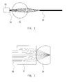
- FIG. 2 is a diagram showing a schematic illustration of a spherical titanium-containing oxide glass used as a coupling lens for optical communications.
- a titanium-containing oxide glass 21 can be used as a coupling lens that condenses a beam 24 emitted by a semiconductor laser 22 and couples it to a single-mode fiber (SMF) 23.
- SMF single-mode fiber
- a material with a high refractive index such as a titanium-containing oxide glass of the present invention, is suitable as a coupling ball lens.
- the refractive index preferably should be 2.0 or more.
- FIG. 3 shows an example of an objective lens using a gradient index rod lens 31 combined with a ball lens 32 which has been processed into a dome shape by truncating a sphere.
- the figure also shows a beam 33.
- the hemispherical, or superhemispherical lens (a planarly truncated sphere, or more specifically, a shape obtained by cutting off a part of the sphere along a plane orthogonal to the center line of the sphere) acts to increase NA (numerical aperture) when placed in front of a focal point.
- NA numbererical aperture
- NA increases as the refractive index of the SIL is increased.
- a titanium-containing oxide glass of the present invention has a notably high refractive index, and therefore suitably is used as a SIL.
- the composition of each sample is shown in Table 1-1 and Table 1-2.
- raw material powders were weighed and mixed to obtain the sample compositions shown in Table 1-1 and Table 1-2.
- the glass raw material prepared as above was used to make glass samples.
- the levitation apparatus shown in FIG. 1 was used.
- a 2 mm 2 glass raw material was placed in the gas levitation furnace 2, and the material was levitated therein under the gas pressure of the compressed air gas flowing at the flow rate adjusted by the flow-rate adjuster 4.
- a laser beam was shone on the levitating raw material to heat and melt the material at a temperature equal to or greater than the melting point of the material.
- the material was heated to the appropriate temperature while measuring the temperature of the material with the radiation thermometer 11, and while monitoring the melting state of the material on the monitor 8 by observing the image captured by the imaging unit 7, taking into account the evaporation and the melting state of the material.
- the gas flow rate was adjusted while monitoring the levitation state of the raw material on the monitor 8, so as to levitate the molten raw material stably. After the raw material has melted completely, the molten state was maintained for 2 minutes to remove bubbles formed in the raw material melt. Thereafter, the laser beam was turned off to quench the raw material melt at a cooling rate of 1,000°C/sec. As a result, the material solidified. Note that no exothermic peak due to crystal solidification was observed in any of the cooling curves of the samples shown in Table 1.
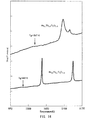
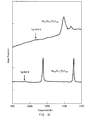
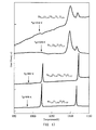
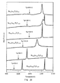
- the measurement result of each sample is shown in FIG. 4 through FIG. 22 . It can be seen from the results that the samples in FIG. 4 through FIG. 22 all have a glass transition point and a crystallization temperature. In other words, the results confirmed that all samples shown in Table 1-1 and Table 1-2 are vitreous at room temperature.
- the samples prepared in this example contain an element represented by M2, except for La 1.0 Ti 2.25 O 6 of sample 1-5, and Nd 1.0 Ti 2 O 5.5 of sample 1-9 (x > 0).
- the refractive index of glass is related to the mass (atomic number) of the element. Generally, the refractive index increases as the mass (atomic number) of the element becomes larger.
- the refractive index was shown to increase by the inclusion of the M2 element, and particularly, by the inclusion of a lanthanoid element, used as a substituting element (M2), having a larger atomic number than Ba.
- lanthanoid elements having two ion valence numbers for example, Er 2+ , Er 3+ ) react with oxygen by undergoing changes in valence in a molten state, and thereby absorb bubbles in the melt (4ErO + O 2 ⁇ 2Er 2 O 3 ).
- the bubbles in the glass can be removed by selecting M2 from such elements.
- the composition of each sample is shown in Table 2.
- the method of preparing the glass raw material is as in Example 1. Further, the glass samples were produced by using the same apparatus and method as those used in Example 1.
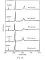
- the measurement result of each sample is shown in FIG. 23 . It can be seen from the results that the samples in FIG. 23 all have a glass transition point Tg and a crystallization temperature. In other words, the results confirmed that all samples shown in Table 2 are vitreous at room temperature.
- the composition of each sample is shown in Table 3-1 and Table 3-2.
- the method of preparing the glass raw material is as in Example 1. Further, the glass samples were produced by using the same apparatus and method as those used in Example 1.
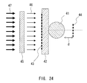
- the calculation of refractive index was performed by measuring a focal point with the sample spherical glass in place. Specifically, as shown in FIG. 24 , a spherical glass 41 under measurement was disposed on a glass substrate 42, and light 46 of a predetermined wavelength was shone on a side of the glass substrate 42 opposite to a side where the spherical glass 41 was arranged. The focal point from the surface of the spherical glass 41 then was measured with a microscope. The focal point was measured by measuring distance d from the surface of the spherical lens 41 to a pattern image 44, which is the image of a pattern 43 formed on the irradiated surface of the glass substrate 42.
- the light of a predetermined wavelength was obtained through an interference filter 45 that allows for passage of this wavelength.
- the refractive index was measured at the wavelengths of 486 nm, 589 nm, and 658 nm.
- the figure also shows white light 47.
- the optical thickness of the glass substrate 42 at each measurement wavelength was determined by measuring the difference between two focal points respectively focused on the both surfaces, using a microscope.
- the diameter of the spherical glass 41 was measured by measuring the difference between two focal points respectively focused on the surface of the glass substrate 42 in contact with the spherical glass 41, and on the surface of the spherical glass on the opposite side.
- the glass samples 3-1 through 3-46 represented by the formula Ba 1-x (M2) x Ti y2 O z have refractive indices of 2.0 or more at 0.486 ⁇ m, 0.589 ⁇ m, and 0.658 ⁇ m in the visible light range, and many of the compositions have refractive indices of 2.1 or more. Further, many samples have diameters of 1 mm or more.
- the samples shown with two elements under the column M2 used two Ba-substituting elements, and the values in brackets indicate the contents of the elements used. The same notation is used below.
- the refractive index was shown to increase as the value of x was increased with an increase in mass (atomic number) of the element M2.
- the upper limit of the content x of M2 as the Ba-substituting element is related to the difference in ion radius between Ba and M2 (r Ba - r M2 ), and x increases as the difference becomes smaller.
- the coordination number of the oxygen in the glass is eight, the difference in ion radius between Ba and the lanthanoid element has the following relationship.
- the maximum value of x for La which has the smallest ion radius difference from Ba
- the maximum value of x for Lu which has the largest ion radius difference from Ba (sample 1-20). This suggests that the value of x for the lanthanoid elements can be as high as 0.5.
- the composition of each sample is shown in Table 4.
- the method of preparing the glass raw material is as in Example 1. Further, the glass samples were produced by using the same apparatus and method as those used in Example 1.
- the glass samples 4-1 to 4-7 represented by the formula La 1-x (M2) x Ti y2 O z have considerably high refractive indices of 2.2 or more at 0.486 ⁇ m, 0.589 ⁇ m, and 0.658 ⁇ m in the visible light range. Some of the samples have a diameter of 1 mm or more.
- the composition of each sample is shown in Table 5.
- the method of preparing the glass raw material is as in Example 1. Further, the glass samples were produced by using the same apparatus and method as those used in Example 1.
- the glass samples 5-1 through 5-3 represented by the formula Nd 1-x (M2) x Ti y2 O z have considerably high refractive indices of 2.2 or more at 0.486 ⁇ m, 0.589 ⁇ m, and 0.658 ⁇ m in the visible light range.
- the diameter was 1 mm or more.
- This example indicates that the use of the element Nd, heavier than Ba, for M1 further can improve the refractive index of the titanium-containing oxide glass.
- the sample of the composition Nd 0.94 Er 0.05 Yb 0.01 Ti 2 O 5.5 , containing the multiple elements Er and Yb for M2, has the highest refractive index nd 2.388 in this example.
- the mixture was sintered at about 800°C to prepare a solid, powder sinter.
- the sinter was placed in the gas levitation furnace 2 shown in FIG. 1 , and the raw material was levitated therein by the gas pressure of the compressed air gas flowing at the flow rate adjusted by the flow-rate adjuster 4.
- a laser beam was shone on the levitating raw material to heat and melt the material at a temperature equal to or greater than the melting point (here, 1,450°C) of the material.
- the material was heated while measuring the temperature of the material with the radiation thermometer 11, and while monitoring the melting state of the material on the monitor 8 by observing the image captured by the imaging unit 7, taking into account the evaporation and the complete fusion of the material.
- the gas flow rate was adjusted while monitoring the levitation state of the material on the monitor 8, so as to stably levitate the raw material melt.
- the molten state was maintained for a predetermined time period to remove bubbles formed in the raw material melt. Thereafter, the laser beam was turned off to quench and solidify the raw material melt.
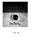
- FIG. 25 shows a optical micrograph of the resulting lanthanum-titanium-containing oxide glass.
- a spherical glass was obtained that had a diameter of about 2 mm, and good transparency for visible light rays, as shown in FIG. 25 .
- the sample was measured using DTA.
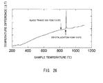
- the result is shown in FIG. 26 . It can be seen from the measurement result that the sample, on heating, exhibits a glass transition point at about 810°C, and, on further heating, makes a transition from supercooled liquid to crystal at 876°C. Thus, it can be said that the sample is in the glass state up to a temperature of about 800°C.
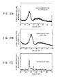
- the X-ray diffraction pattern of the sample also was measured (A) without annealing (room temperature), (B) with annealing at 790°C for 1 minute, and (C) with annealing at 900°C.
- the measurement results are shown in FIG. 27A, FIG. 27B, and FIG. 27C , respectively.
- the sample annealed at 900°C has a diffraction pattern with a sharp peak characteristic of the crystal, showing a transition from glass to crystal.
- the unannealed sample as does the sample annealed at 790°C for 1 minute ( FIG. 28B ), has a diffraction pattern represented by a wide curve characteristic of the glass ( FIG. 27A ), and no sharp peak is observed that indicates the presence of a crystal.
- the refractive index of the sample was measured at two different wavelengths (632.8 nm and 1,313 nm) at room temperature.
- the measurement result is shown in Table 6.
- the measurement of refractive index was performed using a prism coupling method, using a refractive index measurement device (Model 2010 Prism Coupler; Metricon). Measurement accuracy was ⁇ 0.001.
- the mixture was sintered at about 800°C to prepare a solid, powder sinter.
- the sinter then was used to prepare the sample, according to the method described in Example 6.
- the sample was confirmed as a glass by using the same techniques described in Example 6 (DTA measurement, and X-ray diffraction pattern).
- the refractive index at the wavelength of 632.8 nm was 2.313, as measured according to the method of Example 6.
- the mixture was sintered at about 800°C to prepare a solid, powder sinter.
- the sinter then was used to prepare the sample, according to the method described in Example 6.
- the sample was confirmed as a glass by using the same techniques described in Example 6 (DTA measurement, and X-ray diffraction pattern).
- the refractive index at the wavelength of 632.8 nm was 2.312, as measured according to the method of Example 6.
- lanthanum-titanium-containing oxide glass samples 9-1 through 9-22 represented by the formula La 1-x (M2) x (Ti 1-y1 (M3) y1 ) y2 O z were prepared.
- the composition of each sample is shown in Table 7 and Table 8.
- the method used to prepare the samples is as in Example 6.
- the samples were analyzed by using the same techniques (DTA, and X-ray diffraction pattern) described in Example 6. The measurements confirmed that the samples were all glass, as shown in Table 7 and Table 8.
- the sample diameter, and the color of each sample checked by visual inspection also are shown in Table 7 and Table 8.
- Samples 9-23 through 9-25 of the compositions shown in Table 9 also were prepared according to the method of Example 6. However, none of these samples vitrified.
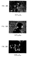
- FIG. 28A, FIG. 28B, and FIG. 28C show optical micrographs of the titanium-containing oxide glasses. As shown in FIG. 28A, FIG. 28B, and FIG. 28C , vitrification also was possible with the compositions of this example.
- the glass of the composition CeTi 2.25 O 6.5 shown in FIG. 28B was black in color, and had a diameter of 1 mm or less.
- the glass of the composition PrTi 2.25 O 6.3 shown in FIG. 28C was green in color, and had a diameter of 1 mm or less.
- the present invention provides a titanium-containing oxide glass and a method for production thereof that can produce a conventionally unavailable bulk glass having a high refractive index in the visible light range. Further, with a producing method of the present invention, a bulk glass having a high refractive index can be produced conveniently in a short time period.
- the present invention is therefore suitable for optical parts such as a lens.
Landscapes
- Chemical & Material Sciences (AREA)
- Engineering & Computer Science (AREA)
- Materials Engineering (AREA)
- Organic Chemistry (AREA)
- Life Sciences & Earth Sciences (AREA)
- Chemical Kinetics & Catalysis (AREA)
- General Chemical & Material Sciences (AREA)
- Geochemistry & Mineralogy (AREA)
- Manufacturing & Machinery (AREA)
- Glass Compositions (AREA)
Abstract
Description
- The present invention relates to a titanium-containing oxide glass, and a method for production thereof, and particularly to a titanium-containing oxide glass having a high refractive index, and a method for production thereof.
- The properties of a glass material can be varied in desirable ways by appropriately selecting the components of the glass composition, and by varying the proportion of each component. For this reason, glass materials have been used in many different applications including electronics and optics.
- However, depending on the composition, the material undergoes crystal precipitation or phase separation, which makes it difficult to vitrify the material uniformly. Further, some components do not melt even under high temperature, and remain as an unmelted solid. That is, there are many compositions that are difficult to vitrify with the use of a common method in which a batch of raw material is placed in a ceramic or platinum crucible and melted in a high-temperature furnace. Many other compositions are only usable to produce a powder or a flaky glass, and cannot produce a mass or a bulk glass more voluminous than a powder or a flaky glass. For example, titanium oxide (TiO2), known as a high refractive-index glass material (see, for example, Precision Molding Technology of Low-Melting and Free-lead Glass Outlined from Recent Japanese Patents (2), Materials Integration, Vo1.18, No. 10, (2005), p.58-66), is expected to find applications in the field of optics. However, because titanium oxide easily crystallizes, it has been difficult to produce a bulk glass using titanium oxide as a main material. Attempts have been made to obtain glass by rapidly roller quenching a melt prepared from a mixture of titanium oxide and lanthanum oxide (La2O3). However, this method is only capable of producing a laminar glass, not a bulk glass.
- There have been proposed methods of producing a single crystal piece or a ceramic of barium-titanium oxide, in which the barium-titanium oxide is melted and solidified in the levitation state (levitation method; see
JP2005-53726A JP2005-213083A - An object of the present invention is to provide a titanium-containing oxide glass of a bulk form, which is not available conventionally, and is expected to have a high refractive index. The invention also provides a method for producing such a titanium-containing oxide glass of a bulk form.
- A titanium-containing oxide glass of the present invention is of a bulk form, and essentially has a composition represented by the formula (M1)1-x(M2)x(Ti1-y1(M3)y1)y2Oz. M1 is one element selected from Ba, La, Ce, Pr, Nd, Sm, Eu, Gd, Tb, Dy, Ho, Er, Tm, Yb, Lu, Na, and Ca. M2 is at least one element selected from Mg, Ba, Ca, Sr, La, Ce, Pr, Nd, Sm, Eu, Gd, Tb, Dy, Ho, Er, Tm, Yb, Lu, Na, Sc, Y, Hf, Bi, and Ag. M3 is at least one element selected from V, Cr, Mn, Fe, Co, Ni, Cu, Zn, Zr, Nb, Mo, Ru, Rh, Pd, Al, Si, P, Ga, Ge, In, Sn, Sb, and Te. The symbols x, y1, y2, and Z satisfy:


As used herein, a "glass" refers to a substance that exhibits a glass transition point (Tg) in a measurement such as DTA. Further, as used herein, the term "essentially" means that the titanium-containing oxide glass may include no more than 1 mol%, preferably no more than 0.5 mol%, and more preferably no more than 0.1 mol% of impurities. - A titanium-containing oxide glass of the present invention contains titanium oxide, making it possible to increase its refractive index. Further, because a titanium-containing oxide glass of the present invention is of a bulk form and has a high transmittance for visible light, it can be used suitably as a material of, for example, optical parts such as a lens.
- A producing method of a titanium-containing oxide glass of the present invention is a method for producing a titanium-containing oxide glass of the present invention. The method includes:
- (a) heating and melting a raw material adjusted to have a predetermined composition, with the raw material being levitated in air; and
- (b) cooling the raw material after melting.
In the descriptions below, the term "levitation method" is used to refer to the method in which a raw material is melted in a levitation state in air. - In a producing method of a titanium-containing oxide glass of the present invention, a raw material is melted without making contact with a container such as a crucible, prior to cooling. This makes it possible to vitrify even compositions containing large amounts of titanium oxide, which generally is believed to cause difficulties in vitrification. For example, vitrification is difficult in compositions containing materials that easily crystallize. In such compositions, crystal precipitation often occurs in areas of contact between the container and the glass material being melted. On the other hand, in a method of the present invention, the raw material is melted and cooled without making contact with the container, inhibiting crystal precipitation of the titanium oxide. This enables production of a titanium-containing oxide glass of a bulk form. Further, with a method of the present invention, the titanium-containing oxide glass can be conveniently produced in a short time period.
-
-
FIG. 1 is a diagram schematically illustrating an example of a gas levitation apparatus used in a producing method of a titanium-containing oxide glass of the present invention. -
FIG. 2 is a diagram illustrating an example of a titanium-containing oxide glass of the present invention being used as a coupling lens. -
FIG. 3 is a diagram illustrating an example of a titanium-containing oxide glass of the present invention being used as a SIL. -
FIG. 4 is a chart representing a result of differential thermal analysis (DTA) performed on a sample prepared in Example 1. -
FIG. 5 is a chart representing a result of differential thermal analysis (DTA) performed on a sample prepared in Example 1. -
FIG. 6 is a chart representing a result of differential thermal analysis (DTA) performed on a sample prepared in Example 1. -
FIG. 7 is a chart representing a result of differential thermal analysis (DTA) performed on a sample prepared in Example 1. -
FIG. 8 is a chart representing a result of differential thermal analysis (DTA) performed on a sample prepared in Example 1. -
FIG. 9 is a chart representing a result of differential thermal analysis (DTA) performed on a sample prepared in Example 1. -
FIG. 10 is a chart representing a result of differential thermal analysis (DTA) performed on a sample prepared in Example 1. -
FIG. 11 is a chart representing a result of differential thermal analysis (DTA) performed on a sample prepared in Example 1. -
FIG. 12 is a chart representing a result of differential thermal analysis (DTA) performed on a sample prepared in Example 1. -
FIG. 13 is a chart representing a result of differential thermal analysis (DTA) performed on a sample prepared in Example 1. -
FIG. 14 is a chart representing a result of differential thermal analysis (DTA) performed on a sample prepared in Example 1. -
FIG. 15 is a chart representing a result of differential thermal analysis (DTA) performed on a sample prepared in Example 1. -
FIG. 16 is a chart representing a result of differential thermal analysis (DTA) performed on a sample prepared in Example 1. -
FIG. 17 is a chart representing a result of differential thermal analysis (DTA) performed on a sample prepared in Example 1. -
FIG. 18 is a chart representing a result of differential thermal analysis (DTA) performed on a sample prepared in Example 1. -
FIG. 19 is a chart representing a result of differential thermal analysis (DTA) performed on a sample prepared in Example 1. -
FIG. 20 is a chart representing a result of differential thermal analysis (DTA) performed on a sample prepared in Example 1. -
FIG. 21 is a chart representing a result of differential thermal analysis (DTA) performed on a sample prepared in Example 1. -
FIG. 22 is a chart representing a result of differential thermal analysis (DTA) performed on a sample prepared in Example 1. -
FIG. 23 is a chart representing a result of differential thermal analysis (DTA) performed on a sample prepared in Example 2. -
FIG. 24 is a diagram explaining a measurement method of refractive index. -
FIG. 25 is an optical micrograph of a sample prepared in Example 6. -
FIG. 26 is a chart representing a result of differential thermal analysis (DTA) performed on a sample prepared in Example 6. -
FIG. 27A is an X-ray diffraction pattern of a sample prepared in Example 6. -
FIG. 27B is an X-ray diffraction pattern of a sample prepared in Example 6, taken after annealing at 790°C for 1 minute. -
FIG. 27C is an X-ray diffraction pattern of a sample prepared in Example 6, taken after annealing at 900°C. -
FIG. 28A is an optical micrograph of a sample prepared in Example 10. -
FIG. 28B is an optical micrograph of a sample prepared in Example 10. -
FIG. 28C is an optical micrograph of a sample prepared in Example 10. - The following will describe an embodiment of the present invention. (Titanium-Containing Oxide Glass)
- A titanium-containing oxide glass of the present invention has a composition represented by the formula (M1) 1-x(M2)x(Ti1-y1(M3)y1)y2Oz. As noted above, M1 is one element selected from Ba, La, Ce, Pr, Nd, Sm, Eu, Gd, Tb, Dy, Ho, Er, Tm, Yb, Lu, Na, and Ca. M2 is at least one element selected from Mg, Ba, Ca, Sr, La, Ce, Pr, Nd, Sm, Eu, Gd, Tb, Dy, Ho, Er, Tm, Yb, Lu, Na, Sc, Y, Hf, Bi, and Ag. M3 is at least one element selected from V, Cr, Mn, Fe, Co, Ni, Cu, Zn, Zr, Nb, Mo, Ru, Rh, Pd, Al, Si, P, Ga, Ge, In, Sn, Sb, and Te. Further, x, y1, y2, and Z satisfy:


- M1 may be one element selected from, for example, Ba, La, Ce, Pr, Nd, Sm, and Ca, or one element selected from La, Ce, Pr, Nd, and Sm. Further, M1 may be one element selected from Ba, La, Nd, and Ca, or one element selected from Ba, La, and Nd.
- The value of y1 indicating the content of the element (M3) substituting Ti may be, for example, 0.1 or less, or 0.05 or less.
- In order to realize a high refractive index, it is desirable that the main component TiO2 of a titanium-containing oxide glass of the present invention be partly substituted with oxides having a higher refractive index than TiO2 (refractive index nd = 2.0; see Hajimete garasu wo tsukuru hitono tameni, Masayuki Yamane, Uchida Rokakuho Publishing Co., Ltd., 1989, p.91, Table 5.6 (referred to as "Reference" hereinafter)). Examples of such oxides include ZrO2 (refractive index nd = 2.2 (see Reference)), and Bi2O3 (refractive index nd = 3.2 (see Reference)). Thus, in order to realize a high refractive index, it is preferable that the value of y1 indicating the content of the Ti-substituting element (M3) be 0.05 or more, and more preferably 0.25 or more.
- On the other hand, vitrification may become difficult when the content of Ti (including the content of the Ti-substituting element (M3)), i.e., the value of y2, is too large. It is therefore preferable that the value of y2 be 3 or less.
- From a different aspect, in terms of the oxide content, a titanium-containing oxide glass of the present invention may contain titanium oxide (TiO2) in the amount of, for example, 57 mol% or more, or 80 mol% or more. In this case, the remaining part of the titanium-containing oxide glass of the present invention is essentially the oxide of the non-Ti elements M1, M2, and M3. Note that in the case where the remaining part is essentially La(La2O3), vitrification is possible even when the titanium oxide content is 80 mol% or more, or even 85 mol%.
- For example, when M1 is Ba, or more specifically, when a titanium-containing oxide glass of the present invention has the formula Ba1-x(M2)x(Ti1-y1(M3)y1)y2Oz, the symbols x, y1, y2, and z may satisfy:


- Further, when M1 is Ba, and when M2, substituting Ba, is at least one element selected from La, Ce, Pr, Nd, Sm, Eu, Gd, Tb, Dy, Ho, Er, Tm, Yb, and Lu, the symbols x, y1, y2, and z may satisfy:


and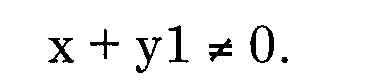
- Further, when M1 is, for example, La, it is preferable to use Zr as the element (M3) substituting Ti, because Zr is a heavy element, similar in chemical properties to Ti.
- A titanium-containing oxide glass of the present invention preferably has a refractive index of 2.0 or more, and more preferably 2.1 or more in the visible light range (a wavelength range of about 380 nm to 780 nm). Further, a titanium-containing oxide glass of the present invention may be a glass having desirable transparency for visible light rays. A titanium-containing oxide glass of the present invention is a bulk, not a powder or any other conventional form. The present invention, which provides a bulk glass having a high refractive index and desirable transparency for visible light rays, is therefore applicable to a wide range of optical parts. As used herein, the meaning of the term "bulk" excludes forms such as a flake or a powder, and the term refers to forms whose minimum dimension (the smallest dimension passing the center of gravity) is 10 µm or more (preferably 50 µm or more).
- For example, when producing a titanium-containing oxide glass of the present invention by a levitation method below, a raw material melt solidifies into a sphere by its surface tension during the cooling process. That is, with a method of the present invention, it is possible to obtain a titanium-containing oxide glass of a spherical form, and a spherical glass having a minimum diameter or 0.5 mm or more, or 1 mm or more. Further, depending on the intended use, a spherical glass having a minimum diameter of 5 cm or less may be produced. It is therefore possible to use a titanium-containing oxide glass of the present invention for optical parts, such as, for example, a spherical lens, without requiring any processing for making the glass or glass surface spherical.
-
FIG. 1 is a diagram showing a schematic illustration of one example of an apparatus (levitation apparatus) used to perform a levitation method in a producing method of a titanium-containing oxide glass of the present invention. - The levitation apparatus includes: a
gas levitation furnace 2, provided to levitate araw material 1 in air; ananchorage 3, provided to prevent movement of thegas levitation furnace 2, and supply a levitation gas to thegas levitation furnace 2; a flow-rate adjuster 4, provided to adjust the flow rate of the gas supplied to theanchorage 3; acarbon dioxide laser 5, which emits a laser beam to heat the levitating,raw material 1; abeam splitter 6, which splits the laser beam from thelaser 5 into two beams; an imaging unit (here, a CCD camera) 7 and amonitor 8 to monitor the levitation state of theraw material 1; aradiation thermometer 11 to measure a temperature of theraw material 1; and acontrol unit 12 to control the laser output and other parameters of thelaser 5. - The
gas levitation furnace 2 includes a gas supply channel (not shown) through which the levitation gas for theraw material 1 flows upward (against the direction of the gravitational force). The gas is supplied into the gas supply channel through a nozzle (not shown) provided underneath (at the bottom of the furnace). Thegas levitation furnace 2 levitates theraw material 1 in air by the pressure of the flowing gas. The flow rate of the flowing gas is related to such factors as the mass of the raw material, and is not particularly limited. For example, when the levitating raw material is 0.005 g to 0.05 g, the gas may flow at a rate of, for example, 0.1 L/min to 0.5 L/min. Thegas levitation furnace 2 is anchored to theanchorage 3 with ananchoring wire 13. Theanchorage 3 has agas supply port 3a. The flow-rate adjuster 4 is connected to thegas supply port 3a of theanchorage 3, and controls the flow rate of the gas supplied into thegas levitation furnace 2. The gas flow rate may be adjusted according to the levitation state of theraw material 1, by monitoring it with theimaging unit 7 and themonitor 8. Theraw material 1 is heated to a predetermined temperature in the levitated state. For the heating, a laser beam is used. The laser beam emitted by thecarbon dioxide laser 5 is split into two laser beams of substantially equal power by thebeam splitter 6. These laser beams respectively are reflected by reflectingmirrors raw material 1 from above and below. The temperature of theraw material 1 is measured by theradiation thermometer 11 in a non-contact manner. The temperature information measured by theradiation thermometer 11 is sent to thecontrol unit 12, which then reads the temperature information, and, according to a predetermined control program, controls the laser output providing heat for theraw material 1, thereby controlling the temperature of theraw material 1. - The following describes a method for producing a glass using the levitation apparatus shown in
FIG. 1 . - First, the
raw material 1 is set in thegas levitation furnace 2, and gas flows into thegas levitation furnace 2 to levitate theraw material 1. The levitation gas may be, for example, air, Ar, or N2. - Next, the
control unit 12 adjusts the laser output of thecarbon dioxide laser 5, which then emits a laser beam to heat theraw material 1. While measuring the temperature of theraw material 1 with theradiation thermometer 11, theraw material 1 is heated to at least its melting point, taking into account the evaporation and the complete fusion of theraw material 1. The heating temperature is not particularly limited, as long as it is equal to or greater than the melting point of theraw material 1. For example, temperatures 100°C to 500°C above the melting point of theraw material 1 are preferable. - The levitation state and the melting state of the
raw material 1 are monitored on themonitor 8, by observing the image captured by theimaging unit 7. Based on this observation, the gas flow rate and the heating temperature are adjusted to levitate the raw material melt stably. Here, in order to remove bubbles formed in the raw material melt, it is preferable to maintain the raw material at a predetermined temperature for a predetermined time period (several minutes), after the raw material has melted completely. The predetermined temperature to maintain the molten raw material is not particularly limited, and it may be, for example, a temperature 100°C to 500°C above the melting point. The time to maintain the molten state is not particularly limited either, and it may be, for example, 0.5 to 5 minutes. - Next, the raw material melt is cooled at a predetermined rate, by adjusting the output of the laser beam hitting the
raw material 1, or by turning off the laser beam. This causes the raw material melt to solidify without undergoing crystallization, thereby obtaining a glass. For example, the cooling rate is preferably 500°C/sec to 1,000°C/sec, and more preferably 1,000°C/sec to 1,500°C/sec. - A glass raw material used in a producing method of the present invention is prepared in such a manner that the product glass has a composition represented by the formula (M1)1-x(M2)x(Ti1-y1(M3)y1)y2Oz. Note that the elements indicated by M1, M2, and M3, and the requirements for x, y1, y2, and z are as described above in conjunction with a titanium-containing oxide of the present invention.
- The following describes an example of a method for preparing a glass raw material used in a producing method of the present invention.
- First, in order to prepare a glass raw material that can form a titanium-containing oxide glass of a desired composition (a predetermined composition represented by (M1)1-x(M2)x(Ti1-y1(M3)y1)y2Oz), raw material powders such as oxide powders are weighed and mixed at a desired weight ratio. For example, when preparing 1 g of a glass raw material of the composition Ba0.7Er0.3Ti2O5.15, 0.43183 g of a BaCO3 powder, 0.16503 g of an Er2O3 powder, and 0.49932 g of a TiO2 powder are weighed out. After being weighed, the raw material powders are wet-blended using ethanol (first wet-blending), followed by pre-firing. Specifically, for example, a dried powder blend is placed in an electric furnace, and the powders are pre-fired at, for example, 1,000°C for 12 hours to sinter the powder blend. After pre-firing, the powders are wet-blended again (second wet-blending), and the blend is press-molded into, for example, a rod shape. Then, the molded product is cut out to obtain a solid of a predetermined size, which is then final-fired at, for example, 1,250°C for 12 hours to obtain a glass raw material.
- The preparation of a glass raw material proceeds in the manner described above. The method for preparing a glass raw material described above is merely an example, and the size of the raw material, and the temperature and the time of pre-firing and final-firing are not limited to the foregoing examples.
- The following describes specific examples of optical parts using a titanium-containing oxide glass of the present invention.
-
FIG. 2 is a diagram showing a schematic illustration of a spherical titanium-containing oxide glass used as a coupling lens for optical communications. A titanium-containingoxide glass 21 can be used as a coupling lens that condenses abeam 24 emitted by asemiconductor laser 22 and couples it to a single-mode fiber (SMF) 23. Because the spherical aberration of a spherical lens becomes smaller as the refractive index increases, a material with a high refractive index, such as a titanium-containing oxide glass of the present invention, is suitable as a coupling ball lens. When using a titanium-containing oxide glass of the present invention as a coupling lens, the refractive index preferably should be 2.0 or more. -
FIG. 3 shows an example of an objective lens using a gradientindex rod lens 31 combined with aball lens 32 which has been processed into a dome shape by truncating a sphere. The figure also shows abeam 33. The hemispherical, or superhemispherical lens (a planarly truncated sphere, or more specifically, a shape obtained by cutting off a part of the sphere along a plane orthogonal to the center line of the sphere) acts to increase NA (numerical aperture) when placed in front of a focal point. Such a lens is called a SIL. NA increases as the refractive index of the SIL is increased. A titanium-containing oxide glass of the present invention has a notably high refractive index, and therefore suitably is used as a SIL. - In this example, titanium-containing oxide glass samples represented by the formula (M1)1-x(M2)xTiy2Oz (y1 = 0, x, y2, and z falling in the ranges noted above) were prepared. The composition of each sample is shown in Table 1-1 and Table 1-2.
[Table 1-1] Sample Composition 1-1 Ba(1-x)CaxTiy2Oz Ba0.9Ca0.1Ti2O5 Ba0.7Ca0.3Ti2O5 1-2 Ca(1-x)BaxTiy2Oz Ca0.7Ba0.3Ti2O5 Ca0.95Ba0.05Ti2O5 1-3 Ba(1-x)SrxTiy2Oz Ba0.95Sr0.05Ti2O5 Ba0.9Sr0.1Ti2O5 Ba0.85Sr0.15Ti2O5 1-4 Ba(1-x)LaxTiy2Oz Ba0.9La0.1Ti2.25O5.55 Ba0.8La0.2Ti2.25O5.6 Ba0.7La0.3Ti2.25O5.65 Ba0.6La0.4Ti2.25O5.7 Ba0.5La0.5Ti2.25O5.75 1-5 La(1-x)BaxTiy2Oz La0.8Ba0.2Ti2.25O5.9 La1.0Ti2.25O6 1-6 Ba(1-x)CexTiy2Oz Ba0.95Ce0.05Ti2O5.025 1-7 Ba(1-x)PrxTiy2Oz Ba0.95Pr0.05Ti2O5.025 Ba0.9Pr0.1Ti2O5.05 1-8 Ba(1-x)NdxTiy2Oz Ba0.7Nd0.3Ti2O5.15 1-9 Nd(1-x)BaxTiy2Oz Nd1.0Ti2O5.5 1-10 Ba(1-x)SmxTiy2Oz Ba0.95Sm0.05Ti2O5.15 Ba0.7Sm0.3Ti2O5.025 [Table 1-2] Sample Composition 1-11 Ba(1-x)EuxTiy2Oz Ba0.7Eu0.30Ti2O5.15 1-12 Ba(1-x)GdxTiy2Oz Ba0.7Gd0.3Ti2O5.15 1-13 Ba(1-x)TbxTiy2Oz Ba0.9Tb0.1Ti2O5.05 Ba0.7Tb0.3Ti2O5.15 1-14 Ba(1-x)DyxTiy2Oz Ba0.95Dy0.05Ti2O5.025 Ba0.9Dy0.1Ti2O5.05 Ba0.7Dy0.3Ti2O5.15 1-15 Ba(1-x)HoxTiy2Oz Ba0.9Ho0.1Ti2O5.05 Ba0.7Ho0.3Ti2O5.15 1-16 Ba(1-x)ErxTiy2Oz Ba0.95Er0.053Ti2O5.025 Ba0.7Er0.3Ti2O5.15 1-17 Ba(1-x)(Er,Yb)xTiy2Oz Ba0.94Er0.05Yb0.01Ti2O5.025 Ba0.69Er0.30Yb0.01Ti1.4O3.94 1-18 Ba(1-x)TmxTiy2Oz Ba0.7Tm0.3Ti2O5.15 1-19 Ba(1-x)YbxTiy2Oz Ba0.95Yb0.05Ti2O5.025 Ba0.9Yb0.1Ti2O5.05 Ba0.7Yb0.3Ti2O5.15 1-20 Ba(1-x)LuxTiy2Oz Ba0.95Lu0.05Ti2O5.025 Ba0.9Lu0.1Ti2O5.05 Ba0.75Lu0.25Ti2O5.125 Ba0.65Lu0.35Ti2O5.175 Ba0.55Lu0.45Ti2O5.225 Ba0.5Lu0.5Ti2O5.25 - First, raw material powders were weighed and mixed to obtain the sample compositions shown in Table 1-1 and Table 1-2. The oxide powders, weighed, were wet-blended in an agate mortar using ethanol (first wet-blending), and the blend was pre-fired. Specifically, the powder blend was placed in an electric furnace after drying, and pre-fired therein at 1,000°C for 12 hours to sinter the powders. Then, the powders were wet-blended again with ethanol (second wet-blending). The powder blend was then placed in a rubber tube, and press-molded into a rod shape under hydrostatic pressure. The resulting rod was cut out to obtain a solid of about 2 mm2 in size, which was then final-fired at 1,250°C for 12 hours to obtain a glass raw material used to prepare the samples.
- The glass raw material prepared as above was used to make glass samples. In this example, the levitation apparatus shown in
FIG. 1 was used. First, a 2 mm2 glass raw material was placed in thegas levitation furnace 2, and the material was levitated therein under the gas pressure of the compressed air gas flowing at the flow rate adjusted by the flow-rate adjuster 4. Then, a laser beam was shone on the levitating raw material to heat and melt the material at a temperature equal to or greater than the melting point of the material. Here, the material was heated to the appropriate temperature while measuring the temperature of the material with theradiation thermometer 11, and while monitoring the melting state of the material on themonitor 8 by observing the image captured by theimaging unit 7, taking into account the evaporation and the melting state of the material. The gas flow rate was adjusted while monitoring the levitation state of the raw material on themonitor 8, so as to levitate the molten raw material stably. After the raw material has melted completely, the molten state was maintained for 2 minutes to remove bubbles formed in the raw material melt. Thereafter, the laser beam was turned off to quench the raw material melt at a cooling rate of 1,000°C/sec. As a result, the material solidified. Note that no exothermic peak due to crystal solidification was observed in any of the cooling curves of the samples shown in Table 1. - Each sample, prepared as above, was measured using a differential thermal analysis (DTA). The measurement result of each sample is shown in
FIG. 4 through FIG. 22 . It can be seen from the results that the samples inFIG. 4 through FIG. 22 all have a glass transition point and a crystallization temperature. In other words, the results confirmed that all samples shown in Table 1-1 and Table 1-2 are vitreous at room temperature. - The samples prepared in this example contain an element represented by M2, except for La1.0Ti2.25O6 of sample 1-5, and Nd1.0Ti2O5.5 of sample 1-9 (x > 0). The refractive index of glass is related to the mass (atomic number) of the element. Generally, the refractive index increases as the mass (atomic number) of the element becomes larger. In the titanium-containing oxide glass samples shown in Table 1-1 and Table 1-2, the refractive index was shown to increase by the inclusion of the M2 element, and particularly, by the inclusion of a lanthanoid element, used as a substituting element (M2), having a larger atomic number than Ba. For example, the refractive index nd, which is 2.14 in BaTi2.25O5, increased to 2.26 in Lu0.7La0.3Ti2.25O5 (M1 = Lu, x = 0.3). Further, lanthanoid elements having two ion valence numbers (for example, Er2+, Er3+) react with oxygen by undergoing changes in valence in a molten state, and thereby absorb bubbles in the melt (4ErO + O2 → 2Er2O3). Thus, the bubbles in the glass can be removed by selecting M2 from such elements.
- In this example, titanium-containing oxide glass samples represented by the formula Ba(Ti1-y1(M3)y1)y2Oz (x = 0, y1 > 0, y2 and z falling in the ranges noted above) were prepared. The composition of each sample is shown in Table 2. The method of preparing the glass raw material is as in Example 1. Further, the glass samples were produced by using the same apparatus and method as those used in Example 1.
[Table 2] Sample Composition 2-1 Ba(Ti(1-y1)Vy1)y2Oz BaTi1.99V0.01O5 2-2 Ba(Ti(1-y1)Cry1)y2Oz BaTi1.98Cr0.02O5 2-3 Ba(Ti(1-y1)Mny1)y2Oz BaTi1.99Mn0.01O5 2-4 Ba(Ti(1-y1)Fey1)y2Oz BaTi1.95Fe0.05O5 2-5 Ba(Ti(1-y1)Cuy1)y2Oz BaTi1.998Cu0.002O5 - Each sample, prepared as above, was measured using a differential thermal analysis (DTA). The measurement result of each sample is shown in
FIG. 23 . It can be seen from the results that the samples inFIG. 23 all have a glass transition point Tg and a crystallization temperature. In other words, the results confirmed that all samples shown in Table 2 are vitreous at room temperature. - The fact that all the titanium-containing oxide glasses of this example has y1 > 0 suggests that the inclusion of the highly magnetic and electrically conductive transitional metal element as the Ti-substituting element (M3) enables production of a glass having magnetic and electrically conductive properties.
- In this example, barium-titanium-containing oxide glass samples 3-1 through 3-46 represented by the formula Ba1-x(M2)xTiy2Oz (x > 0, y1 = 0, y2 and z falling in the ranges noted above) were prepared. The composition of each sample is shown in Table 3-1 and Table 3-2. The method of preparing the glass raw material is as in Example 1. Further, the glass samples were produced by using the same apparatus and method as those used in Example 1.
- Each sample, prepared as above, was measured in regard to diameter and refractive index, and the state of color was checked by visual inspection. The sample diameter was measured using a micrometer.
- In this example, the calculation of refractive index was performed by measuring a focal point with the sample spherical glass in place. Specifically, as shown in
FIG. 24 , aspherical glass 41 under measurement was disposed on aglass substrate 42, andlight 46 of a predetermined wavelength was shone on a side of theglass substrate 42 opposite to a side where thespherical glass 41 was arranged. The focal point from the surface of thespherical glass 41 then was measured with a microscope. The focal point was measured by measuring distance d from the surface of thespherical lens 41 to apattern image 44, which is the image of apattern 43 formed on the irradiated surface of theglass substrate 42. The light of a predetermined wavelength was obtained through aninterference filter 45 that allows for passage of this wavelength. In this example, the refractive index was measured at the wavelengths of 486 nm, 589 nm, and 658 nm. The figure also showswhite light 47. The optical thickness of theglass substrate 42 at each measurement wavelength was determined by measuring the difference between two focal points respectively focused on the both surfaces, using a microscope. The diameter of thespherical glass 41 was measured by measuring the difference between two focal points respectively focused on the surface of theglass substrate 42 in contact with thespherical glass 41, and on the surface of the spherical glass on the opposite side. The refractive index of the spherical glass was determined from the distance d, the optical thickness of theglass substrate 42, and the diameter of thespherical glass 41 so obtained, using geometric optics calculations.[Table 3-1] Sample Ba(1-x)(M2)xTiy2Oz Diameter (mm) Refractive index Color M2 x y2 z 0.486 µm 0.589 µm 0.658 µm 3-1 Ca 0.05 2 5.000 1.5035 2.144 2.110 2.083 Uncolored 3-2 La 0.1 2 5.050 0.8955 2.174 2.132 2.100 Uncolored 3-3 La 0.10 2.25 5.550 0.8660 2.231 2.202 2.181 Uncolored 3-4 La 0.20 2.25 5.600 0.9520 2.189 2.155 2.141 Uncolored 3-5 La 0.30 2.25 5.650 0.9000 2.280 2.245 2.207 Uncolored 3-6 La 0.40 2.25 5.700 0.7455 2.271 2.258 2.239 Uncolored 3-7 La 0.50 2.25 5.750 0.7855 2.323 2.286 2.236 Uncolored 3-8 Ce 0.05 2 5.050 1.3785 2.177 2.144 2.118 Red-purple 3-9 Ce 0.10 2 5.100 0.9610 2.168 2.147 2.115 Red-purple 3-10 Pr 0.10 2 5.050 1.1775 2.192 2.159 2.132 Pale yellow 3-11 Pr(0.10)/ Yb(0.01) 0.11 2 5.055 1.3110 2.204 2.178 2.157 Pale yellow 3-12 Pr 0.20 2 5.100 1.2225 2.254 2.222 2.195 Yellow-green 3-13 Pr 0.30 2 5.150 1.2085 2.237 2.210 2.185 Yellow-green 3-14 Nd 0.05 2 5.025 1.4400 2.156 2.112 2.098 Pale blue 3-15 Nd 0.30 2 5.150 1.0865 2.231 2.210 2.185 Blue 3-16 Sm 0.05 2 5.025 1.4430 2.181 2.143 2.127 Uncolored 3-17 Sm 0.30 2 5.150 1.1610 2.248 2.218 2.195 Pale yellow 3-18 Eu 0.05 2 5.025 1.8900 2.203 2.168 2.146 Uncolored 3-19 Eu 0.30 2 5.150 1.3445 2.241 2.191 2.168 Pale yellow 3-20 Gd 0.05 2 5.025 1.5455 2.184 2.143 2.119 Uncolored 3-21 Gd 0.30 2 5.150 1.0885 2.247 2.214 2.177 Uncolored [Table 3-2] Sample Ba(1-x)(M2)xTiy2Oz Diameter(mm) Refractive index Color M2 x y2 z 0.486 µm 0.589 µm 0.658 µm 3-22 Tb 0.05 2 5.025 1.4510 2.152 2.129 2.092 Pale yellow 3-23 Tb 0.10 2 5.050 1.3995 2.195 2.148 2.125 Pale yellow 3-24 Tb 0.30 2 5.150 1.2905 2.269 2.210 2.184 Yellow 3-25 Dy 0.05 2 5.025 1.3705 2.110 2.076 2.054 Uncolored 3-26 Dy 0.10 2 5.050 1.4120 2.222 2.180 2.164 Uncolored 3-27 Dy 0.30 2 5.150 1.3415 2.209 2.174 2.146 Uncolored 3-28 Ho 0.05 2 5.025 1.4835 2.121 2.090 2.071 Pale orange 3-29 Ho 0.10 2 5.050 1.5335 2.138 2.103 2.091 Pale orange 3-30 Ho 0.30 2 5.150 1.3955 2.221 2.188 2.162 Pale orange 3-31 Er 0.02 2 5.010 0.8070 2.173 2.150 2.136 Pale pink 3-32 Er(0.02)/ Yb(0.01) 0.03 2 5.015 0.9600 2.221 2.159 2.143 Pale pink 3-33 Er 0.05 2 5.025 1.3360 2.212 2.175 2.141 Pale pink 3-34 Er(0.05)/ Yb(0.01) 0.06 2 5.030 1.3915 2.208 2.154 2.136 Pale pink 3-35 Er 0.15 2 5.075 1.1775 2.227 2.174 2.149 Pale pink 3-36 Er(0.15)/ Yb(0.01) 0.16 2 5.080 1.271 2.194 2.177 2.148 Pale pink 3-37 Er 0.30 2 5.150 1.6585 2.053 2.023 2.004 Pink 3-38 Er(0.3)/ Yb(0.01) 0.31 2 5.155 1.3975 2.258 2.218 2.188 Pink 3-39 Tm 0.05 2 5.025 1.4970 2.156 2.120 2.097 Uncolored 3-40 Tm 0.30 2 5.150 1.3245 2.154 2.114 2.093 Uncolored 3-41 Yb 0.05 2 5.025 1.4780 2.156 2.123 2.104 Uncolored 3-42 Yb 0.10 2 5.050 1.2480 2.215 2.167 2.146 Uncolored 3-43 Yb 0.30 2 5.150 1.3035 1.943 1.916 1.898 Uncolored 3-44 Lu 0.05 2 5.025 1.4315 2.157 2.114 2.092 Uncolored 3-45 Lu 0.3 5 2 5.175 1.4110 2.215 2.174 2.132 Uncolored 3-46 Lu 0.45 2 5.225 1.1280 2.297 2.266 2.244 Uncolored - As shown in Table 3-1 and Table 3-2, the glass samples 3-1 through 3-46 represented by the formula Ba1-x(M2)xTiy2Oz have refractive indices of 2.0 or more at 0.486 µm, 0.589 µm, and 0.658 µm in the visible light range, and many of the compositions have refractive indices of 2.1 or more. Further, many samples have diameters of 1 mm or more. In the tables, the samples shown with two elements under the column M2 used two Ba-substituting elements, and the values in brackets indicate the contents of the elements used. The same notation is used below.
- In the titanium-containing oxide glasses of this example, the refractive index was shown to increase as the value of x was increased with an increase in mass (atomic number) of the element M2. For example, at the wavelength of 0.589 µm, the refractive index nd is 2.202, 2.245, and 2.286 in samples 3-3, 3-5, and 3-7, respectively, in which M1 = Ba, M2 = La, and x = 0.1 (Sample 3-3), 0.3 (Sample 3-5), and 0.5 (Sample 3-7).
- Considering the structure factor of the glass, the upper limit of the content x of M2 as the Ba-substituting element is related to the difference in ion radius between Ba and M2 (rBa - rM2), and x increases as the difference becomes smaller. When the coordination number of the oxygen in the glass is eight, the difference in ion radius between Ba and the lanthanoid element has the following relationship.
rBa-rLa < rBa-rCe < rBa-rPr < rBa-rNd < rBa-rsm < rBa-rEu < rBa-rGd < rBa-rTb < rBa-rDy < rBa-rHo < rBa-rEr < rBa-rTm < rBa-rLu - In the titanium-containing oxide glass samples of the foregoing examples, the maximum value of x for La, which has the smallest ion radius difference from Ba, is 0.5 (sample 3-7), as is the maximum value of x for Lu, which has the largest ion radius difference from Ba (sample 1-20). This suggests that the value of x for the lanthanoid elements can be as high as 0.5.
- In this example, lanthanum-titanium-containing oxide glass samples 4-1 through 4-7 represented by the formula La1-x(M2)xTiy2Oz (y1 = 0, x, y2, and z falling in the ranges noted above) were prepared. The composition of each sample is shown in Table 4. The method of preparing the glass raw material is as in Example 1. Further, the glass samples were produced by using the same apparatus and method as those used in Example 1.
- Each sample, prepared as above, was measured with regard to diameter and refractive index, and the state of color was checked by visual inspection. The results are shown in Table 4.
[Table 4] Sample La(1-x)(M2)xTiy2Oz Diameter (mm) Refractive index Color M2 x y2 z 0.486 µm 0.589 µm 0.658 µm 4-1 - 0.000 2.25 6.00 1.5065 2.360 2.312 2.287 Uncolored 4-2 Ba 0.1 2.25 5.95 0.891 2.408 2.375 2.335 Uncolored 4-3 Ba 0.2 2 5.400 1.5675 2.40 2.34 2.32 Uncolored 4-4 Ba 0.3 2.25 5.85 0.9350 2.365 2.319 2.278 Uncolored 4-5 Ba 0.4 2.25 5.80 0.982 2.304 2.272 2.225 Uncolored 4-6 Er 0.05 2.25 6.00 1.1605 2.411 2.359 2.320 Pale pink 4-7 Er(0.05)/ Yb(0.01) 0.06 2.25 6.00 1.1865 2.385 2.338 2.322 Pale pink - As shown in Table 4, the glass samples 4-1 to 4-7 represented by the formula La1-x(M2)xTiy2Oz have considerably high refractive indices of 2.2 or more at 0.486 µm, 0.589 µm, and 0.658 µm in the visible light range. Some of the samples have a diameter of 1 mm or more.
- La2O3 has a higher refractive index (nd = 2.57; see Reference) than BaO (nd = 1.88; see Reference). Accordingly, the titanium-containing oxide glasses of this example, using La for M1, have higher refractive indices than the titanium-containing oxide glasses using Ba for M1. For example, the titanium-containing oxide glass sample 4-2 of the composition La0.9Ba0.1Ti2.25O5.95 (M1 = La, M2 = Ba, x = 0.1, y2 = 2.25, z = 5.95) had the highest refractive index nd = 2.375 among the samples measured at the wavelength of 0.589 µm in this example.
- In this example, neodymium-titanium-containing oxide glass samples 5-1 through 5-3 represented by the formula Nd1-x(M2)xTiy2Oz (y1 = 0, x, y2, and z falling in the ranges noted above) were prepared. The composition of each sample is shown in Table 5. The method of preparing the glass raw material is as in Example 1. Further, the glass samples were produced by using the same apparatus and method as those used in Example 1.
- Each sample, prepared as above, was measured with regard to diameter and refractive index, and the state of color was checked by visual inspection. The results are shown in Table 5.
[Table 5] Sample Nd(1-x)(M2)xTiy2Oz Diamete r(mm) Refractive index Color M2 x y2 z 0.486 µm 0.589 µm 0.658 µm 5-1 - 0.00 2.00 5.50 1.0600 2.349 2.297 2.271 Purple 5-2 Er 0.05 2.00 5.50 1.0485 2.383 2.356 2.329 Purple 5-3 Er(0.05)/ Yb(0.01) 0.06 2.00 5.50 1.1120 2.425 2.388 2.333 Purple - As shown in Table 5, the glass samples 5-1 through 5-3 represented by the formula Nd1-x(M2)xTiy2Oz have considerably high refractive indices of 2.2 or more at 0.486 µm, 0.589 µm, and 0.658 µm in the visible light range. The diameter was 1 mm or more.
- This example indicates that the use of the element Nd, heavier than Ba, for M1 further can improve the refractive index of the titanium-containing oxide glass. Specifically, the sample of the composition Nd0.94Er0.05Yb0.01Ti2O5.5, containing the multiple elements Er and Yb for M2, has the highest refractive index nd = 2.388 in this example.
- In this example, a lanthanum-titanium-containing
oxide glass sample 6 represented by the formula LaTi2.25O6 (x = 0, y1 = 0, y2 = 2.25, z = 6) was prepared. - First, a La2O3 powder and a TiO2 powder were mixed in such proportions that a glass raw material of the composition LaTi2.25O6 (molar ratio, La2O3:TiO2 = 1:4.5) was obtained. The mixture was sintered at about 800°C to prepare a solid, powder sinter. The sinter was placed in the
gas levitation furnace 2 shown inFIG. 1 , and the raw material was levitated therein by the gas pressure of the compressed air gas flowing at the flow rate adjusted by the flow-rate adjuster 4. Then, a laser beam was shone on the levitating raw material to heat and melt the material at a temperature equal to or greater than the melting point (here, 1,450°C) of the material. The material was heated while measuring the temperature of the material with theradiation thermometer 11, and while monitoring the melting state of the material on themonitor 8 by observing the image captured by theimaging unit 7, taking into account the evaporation and the complete fusion of the material. The gas flow rate was adjusted while monitoring the levitation state of the material on themonitor 8, so as to stably levitate the raw material melt. After the raw material has melted completely, the molten state was maintained for a predetermined time period to remove bubbles formed in the raw material melt. Thereafter, the laser beam was turned off to quench and solidify the raw material melt. -
FIG. 25 shows a optical micrograph of the resulting lanthanum-titanium-containing oxide glass. In this example, a spherical glass was obtained that had a diameter of about 2 mm, and good transparency for visible light rays, as shown inFIG. 25 . - To confirm that the sample obtained in this example is a glass, the following techniques were used.
- First, the sample was measured using DTA. The result is shown in
FIG. 26 . It can be seen from the measurement result that the sample, on heating, exhibits a glass transition point at about 810°C, and, on further heating, makes a transition from supercooled liquid to crystal at 876°C. Thus, it can be said that the sample is in the glass state up to a temperature of about 800°C. - The X-ray diffraction pattern of the sample also was measured (A) without annealing (room temperature), (B) with annealing at 790°C for 1 minute, and (C) with annealing at 900°C. The measurement results are shown in
FIG. 27A, FIG. 27B, and FIG. 27C , respectively. As clearly shown inFIG. 27C , the sample annealed at 900°C has a diffraction pattern with a sharp peak characteristic of the crystal, showing a transition from glass to crystal. On the other hand, the unannealed sample, as does the sample annealed at 790°C for 1 minute (FIG. 28B ), has a diffraction pattern represented by a wide curve characteristic of the glass (FIG. 27A ), and no sharp peak is observed that indicates the presence of a crystal. - These results confirmed that the sample obtained in this example was indeed a glass.
- The refractive index of the sample was measured at two different wavelengths (632.8 nm and 1,313 nm) at room temperature. The measurement result is shown in Table 6. In this example, the measurement of refractive index was performed using a prism coupling method, using a refractive index measurement device (Model 2010 Prism Coupler; Metricon). Measurement accuracy was ±0.001.
[Table 6] Wavelength (nm) Refractive index 1,313 2.223 632.8 2.291 - In this example, a lanthanum-titanium-containing
oxide glass sample 7 represented by the formula LaTi2.75O7 (x = 0, y1 = 0, y2 = 2.75, z = 7) was prepared. - First, a La2O3 powder and a TiO2 powder were mixed in such proportions that a glass raw material of the composition LaTi2.75O7 (molar ratio, La2O3:TiO2 = 1:5.5) was obtained. The mixture was sintered at about 800°C to prepare a solid, powder sinter. The sinter then was used to prepare the sample, according to the method described in Example 6. The sample was confirmed as a glass by using the same techniques described in Example 6 (DTA measurement, and X-ray diffraction pattern). The refractive index at the wavelength of 632.8 nm was 2.313, as measured according to the method of Example 6.
- In this example, a lanthanum-titanium-containing
oxide glass sample 8 represented by the formula LaTi3.15Zr0.06O7.90 (x = 0, y1 = 0.019, y2 = 3.21, z = 7.9) was prepared. - First, a La2O3 powder and a TiO2 powder were mixed in such proportions that a glass raw material of the composition LaTi3.15Zr0.06O7.90 (molar ratio, La2O3:TiO2:ZrO2 = 0.135:0.85:0.015) was obtained. The mixture was sintered at about 800°C to prepare a solid, powder sinter. The sinter then was used to prepare the sample, according to the method described in Example 6. The sample was confirmed as a glass by using the same techniques described in Example 6 (DTA measurement, and X-ray diffraction pattern). The refractive index at the wavelength of 632.8 nm was 2.312, as measured according to the method of Example 6.
- In this example, lanthanum-titanium-containing oxide glass samples 9-1 through 9-22 represented by the formula La1-x(M2)x(Ti1-y1(M3)y1)y2Oz were prepared. The composition of each sample is shown in Table 7 and Table 8. The method used to prepare the samples is as in Example 6. The samples were analyzed by using the same techniques (DTA, and X-ray diffraction pattern) described in Example 6. The measurements confirmed that the samples were all glass, as shown in Table 7 and Table 8. The sample diameter, and the color of each sample checked by visual inspection also are shown in Table 7 and Table 8. Samples 9-23 through 9-25 of the compositions shown in Table 9 also were prepared according to the method of Example 6. However, none of these samples vitrified.


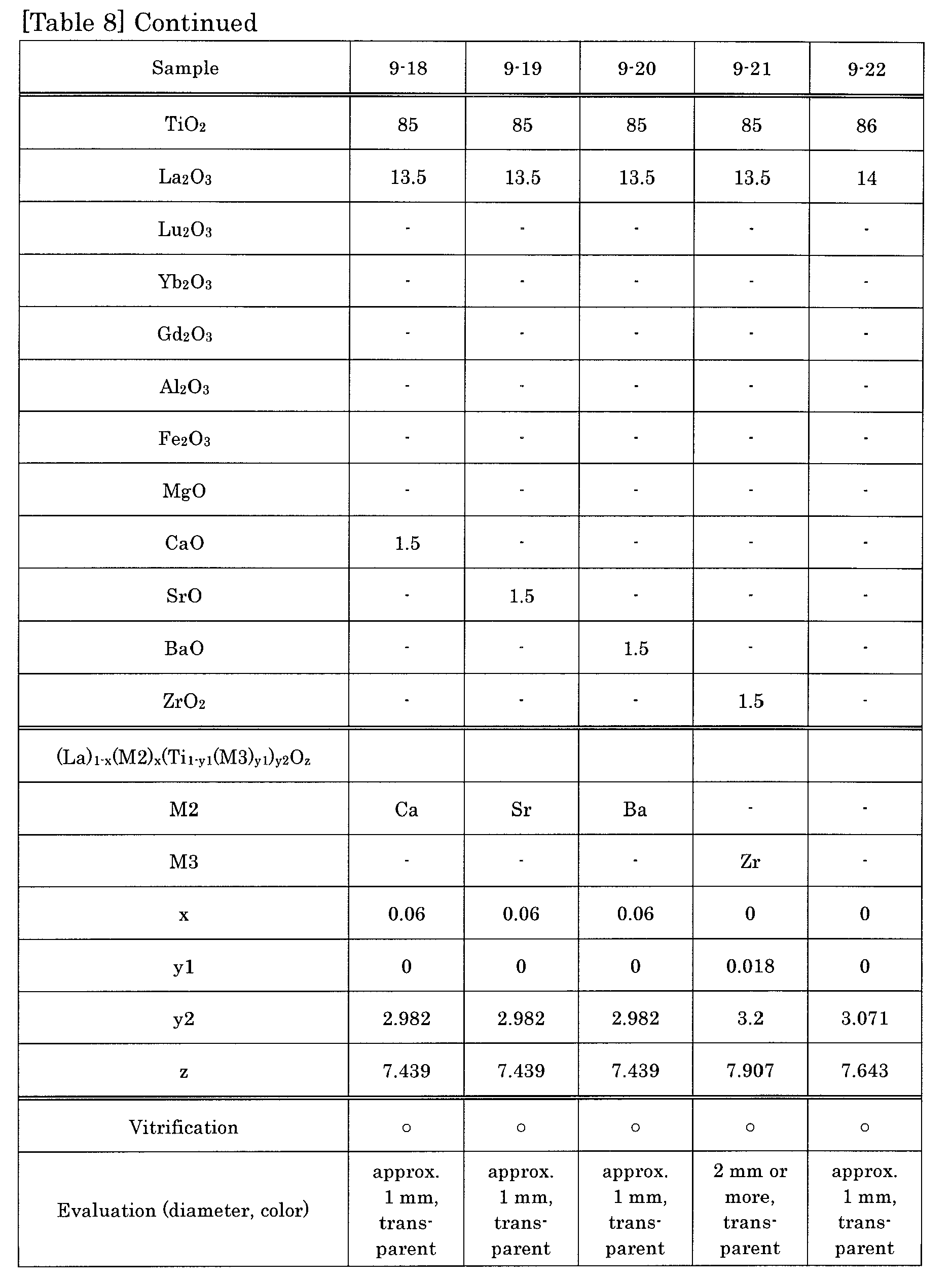
[Table 9] Sample 9-23 9-24 9-25 TiO2 87.5 87.5 85 La2O3 8.75 11.25 12 Lu2O3 3.75 - - Yb2O3 - 1.25 - Sc2O3 - - - Y2O3 - - - Ga2O3 - - - ZrO2 - - 3 Nb2O5 - - - SuO - - - (La)1-x(M2)x(Ti1-y1(M3)y1)y2Oz M2 Lu Yb - M3 - - Zr x 0.17 0.13 0 y1 0 0 0.017 y2 4.268 3.431 3.6 z 8.5 8.5 8.833 Vitrification × × × Evaluation - - - - The results shown in Table 7 and Table 8 confirmed that the vitrification of the lanthanum-titanium-containing oxide glass is possible even when the titanium in the composition is partly substituted with other elements (M3), and when the lanthanum in the composition is partly substituted with other elements (M2).
- The results shown in Table 9 confirmed that vitrification is difficult when the sum of the Ti content and the content of the Ti-substituting element (M3) in the composition is too large.
- In this example, titanium-containing oxide glass samples represented by the formulae SmTi2.25O6 (x = 0, y1 = 0, y2 = 2.25, z = 6), CeTi2.25O6.5 (x = 0, y1 = 0, y2 = 2.25, z = 6.5), PrTi2.25O6.3 (x = 0, y1 = 0, y2 = 2.25, z = 6.3) were prepared according to the method of Example 6.
FIG. 28A, FIG. 28B, and FIG. 28C show optical micrographs of the titanium-containing oxide glasses. As shown inFIG. 28A, FIG. 28B, and FIG. 28C , vitrification also was possible with the compositions of this example. The glass of the composition SmTi2.25O6 shown inFIG. 28A was pale green in color, and had a diameter of 1 mm or less. The glass of the composition CeTi2.25O6.5 shown inFIG. 28B was black in color, and had a diameter of 1 mm or less. The glass of the composition PrTi2.25O6.3 shown inFIG. 28C was green in color, and had a diameter of 1 mm or less. - The present invention provides a titanium-containing oxide glass and a method for production thereof that can produce a conventionally unavailable bulk glass having a high refractive index in the visible light range. Further, with a producing method of the present invention, a bulk glass having a high refractive index can be produced conveniently in a short time period. The present invention is therefore suitable for optical parts such as a lens.
Claims (11)
- A titanium-containing oxide glass of a bulk form essentially having a composition represented by the formula (Ml)1-x(M2)x(Ti1-y1(M3)y1)y2Oz,
wherein M1 being one element selected from Ba, La, Ce, Pr, Nd, Sm, Eu, Gd, Tb, Dy, Ho, Er, Tm, Yb, Lu, Na, and Ca,
M2 being at least one element selected from Mg, Ba, Ca, Sr, La, Ce, Pr, Nd, Sm, Eu, Gd, Tb, Dy, Ho, Er, Tm, Yb, Lu, Na, Sc, Y, Hf, Bi, and Ag,
M3 being at least one element selected from V, Cr, Mn, Fe, Co, Ni, Cu, Zn, Zr, Nb, Mo, Ru, Rh, Pd, Al, Si, P, Ga, Ge, In, Sn, Sb, and Te, and
x, y1, y2, and z satisfying:



- The titanium-containing oxide glass according to claim 1, wherein M1 is one element selected from Ba, La, Ce, Pr, Nd, Sm, and Ca.
- The titanium-containing oxide glass according to claim 2, wherein M1 is one element selected from Ba, La, Nd, and Ca.
- The titanium-containing oxide glass according to claim 1,
wherein M1 is Ba, and
wherein x, y1, y2, and z satisfy:


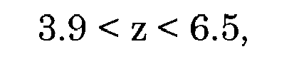


- The titanium-containing oxide glass according to claim 1,
wherein M1 is Ba,
wherein M2 is at least one element selected from La, Ce, Pr, Nd, Sm, Eu, Gd, Tb, Dy, Ho, Er, Tm, Yb, and Lu, and
wherein x, y1, y2, and z satisfy:


and
- The titanium-containing oxide glass according to claim 1, wherein M1 is La, and wherein M3 is Zr.
- The titanium-containing oxide glass according to claim 1, wherein the glass has a refractive index of 2.0 or more in a visible light range.
- The titanium-containing oxide glass according to claim 1, wherein the glass is spherical.
- The titanium-containing oxide glass according to claim 8, wherein the glass is a sphere having a minimum diameter of 0.1 mm or more.
- A method for producing a titanium-containing oxide glass of claim 1, the method comprising:(a) heating and melting a raw material adjusted to have a predetermined composition, with the raw material being levitated in air; and(b) cooling the raw material after melting.
- The method according to claim 10, further comprising maintaining the raw material in a molten state for a predetermined time period, after the step (a) and before the step (b).
Applications Claiming Priority (2)
| Application Number | Priority Date | Filing Date | Title |
|---|---|---|---|
| JP2006250111A JP4953234B2 (en) | 2006-09-14 | 2006-09-14 | Titanium-based oxide glass and method for producing the same |
| PCT/JP2007/067854 WO2008032789A1 (en) | 2006-09-14 | 2007-09-13 | Titanium-containing oxide glass and method for production thereof |
Publications (2)
| Publication Number | Publication Date |
|---|---|
| EP2062860A1 true EP2062860A1 (en) | 2009-05-27 |
| EP2062860A4 EP2062860A4 (en) | 2013-12-04 |
Family
ID=39183843
Family Applications (1)
| Application Number | Title | Priority Date | Filing Date |
|---|---|---|---|
| EP07807261.8A Withdrawn EP2062860A4 (en) | 2006-09-14 | 2007-09-13 | TITANIUM-CONTAINING OXIDE GLASS AND PROCESS FOR PRODUCING THE SAME |
Country Status (8)
| Country | Link |
|---|---|
| US (2) | US7960300B2 (en) |
| EP (1) | EP2062860A4 (en) |
| JP (1) | JP4953234B2 (en) |
| KR (1) | KR101376813B1 (en) |
| CN (1) | CN101516795B (en) |
| CA (1) | CA2663641C (en) |
| TW (1) | TWI396673B (en) |
| WO (1) | WO2008032789A1 (en) |
Cited By (1)
| Publication number | Priority date | Publication date | Assignee | Title |
|---|---|---|---|---|
| CN102002361A (en) * | 2010-11-15 | 2011-04-06 | 四川理工学院 | Titanium dioxide matrix up-conversion luminescent material excited by multi-wavelength laser at low power |
Families Citing this family (29)
| Publication number | Priority date | Publication date | Assignee | Title |
|---|---|---|---|---|
| JP2008189492A (en) * | 2007-02-02 | 2008-08-21 | Japan Aerospace Exploration Agency | OPTICAL ELEMENT, TITANIUM OXIDE GLASS USED FOR THE SAME, AND LIGHT EMITTING METHOD AND LIGHT AMPLIFICATION METHOD USING TITANIUM OXIDE GLASS |
| WO2010071202A1 (en) * | 2008-12-18 | 2010-06-24 | 日本板硝子株式会社 | Glass, and glass processing method |
| CN101747055B (en) * | 2009-12-25 | 2012-05-09 | 陕西科技大学 | Low-temperature sintered magnetoelectric composite medium thick film material and preparation method thereof |
| JP5674233B2 (en) * | 2010-02-01 | 2015-02-25 | 日本電気硝子株式会社 | Mixed raw material for glass production and method for producing glass article |
| US9166222B2 (en) | 2010-11-02 | 2015-10-20 | Envia Systems, Inc. | Lithium ion batteries with supplemental lithium |
| CN102432183B (en) * | 2011-09-08 | 2014-02-26 | 中国科学院过程工程研究所 | A nano-micron titanium oxide glass sphere and its preparation method |
| JP2017154972A (en) * | 2012-12-28 | 2017-09-07 | 日本電気硝子株式会社 | Manufacturing method of glass material |
| JP6385662B2 (en) * | 2012-12-28 | 2018-09-05 | 日本電気硝子株式会社 | Manufacturing method of glass material |
| WO2015125794A1 (en) * | 2014-02-21 | 2015-08-27 | 旭硝子株式会社 | Light-guiding element and video display device |
| CN104030573B (en) * | 2014-06-12 | 2017-02-15 | 中国科学院过程工程研究所 | Colorless niobium oxide glass and preparation method and application thereof |
| JP6507799B2 (en) * | 2014-06-13 | 2019-05-08 | 日本電気硝子株式会社 | Method of manufacturing glass material and manufacturing apparatus of glass material |
| US10773987B2 (en) | 2014-07-14 | 2020-09-15 | Nippon Electric Glass Co., Ltd. | Glass material manufacturing method and glass material manufacturing device |
| JP6628021B2 (en) * | 2015-02-12 | 2020-01-08 | 日本電気硝子株式会社 | Optical glass and manufacturing method thereof |
| JP6681013B2 (en) * | 2015-04-07 | 2020-04-15 | 日本電気硝子株式会社 | Optical glass and manufacturing method thereof |
| CN107250067B (en) | 2015-06-10 | 2020-06-16 | 日本电气硝子株式会社 | Manufacturing method of glass material, manufacturing apparatus of glass material, and glass material |
| CN107250066A (en) * | 2015-06-10 | 2017-10-13 | 日本电气硝子株式会社 | Method for producing glass material |
| US10351464B2 (en) * | 2015-06-22 | 2019-07-16 | Canon Kabushiki Kaisha | Method for manufacturing glass, method for manufacturing lens, and melting apparatus |
| JP6701557B2 (en) * | 2016-01-28 | 2020-05-27 | 日本電気硝子株式会社 | Optical glass and manufacturing method thereof |
| JP6699293B2 (en) * | 2016-03-30 | 2020-05-27 | 日本電気硝子株式会社 | Glass material manufacturing method and manufacturing apparatus |
| CN105906191B (en) * | 2016-04-21 | 2023-06-13 | 中国建材国际工程集团有限公司 | Production method and device of glass microspheres |
| JP6942542B2 (en) * | 2016-07-06 | 2021-09-29 | キヤノン株式会社 | Glass manufacturing method, lens manufacturing method and melting equipment |
| CN109562980B (en) * | 2016-08-26 | 2022-05-06 | 国立大学法人东京大学 | Optical glass, optical elements and optical devices composed of optical glass |
| JP7076981B2 (en) * | 2017-10-25 | 2022-05-30 | キヤノン株式会社 | Manufacturing method of optical glass, optical element, optical equipment and optical glass |
| CN108191213B (en) * | 2017-12-06 | 2021-01-05 | 霖鼎光学(上海)有限公司 | Preparation method of composite fluorescent glass cover |
| JP7202778B2 (en) * | 2017-12-21 | 2023-01-12 | セイコーインスツル株式会社 | Barium dititanate-based ceramics and piezoelectric elements |
| JP6660607B2 (en) * | 2019-03-25 | 2020-03-11 | 日本電気硝子株式会社 | Optical glass and manufacturing method thereof |
| JP7530034B2 (en) * | 2019-04-05 | 2024-08-07 | 日本電気硝子株式会社 | Decorative glass articles |
| CN110304831B (en) * | 2019-07-22 | 2021-11-30 | 中国科学院上海光学精密机械研究所 | Dy-Ag co-doped silicate anti-sputtering plate glass and preparation method thereof |
| WO2024219109A1 (en) * | 2023-04-19 | 2024-10-24 | 株式会社ニコン | Glass composition, and optical element and optical device using same |
Family Cites Families (19)
| Publication number | Priority date | Publication date | Assignee | Title |
|---|---|---|---|---|
| US3293051A (en) * | 1963-08-22 | 1966-12-20 | Cataphote Corp | High titanate glass beads |
| DE1771079B1 (en) | 1968-03-30 | 1971-12-30 | Jenaer Glaswerk Schott & Gen | COUNTER-REDUCTION AND STABILIZATION OF STABLE GLASSES FOR REFLEX PEARLS WITH CRUCIAL VALUES AT LEAST EQUAL LARGE OR EQUAL 2.2 |
| US4082427A (en) * | 1974-07-02 | 1978-04-04 | Fukuoka Tokushu Garasu Kabushiki Kaisha | High refractive index glass compositions |
| JPS5415919A (en) * | 1977-06-07 | 1979-02-06 | Fukuoka Tokushiyu Garasu Kk | Glass having high refractive index |
| JPS5431415A (en) * | 1977-08-15 | 1979-03-08 | Toshiba Kasei Kougiyou Kk | High refractive index glass for use as glass beads |
| JPS5440814A (en) * | 1977-09-06 | 1979-03-31 | Toshiba Kasei Kougiyou Kk | High refractive index glass for use as glass beads |
| JPS59164650A (en) * | 1983-03-10 | 1984-09-17 | Toshiba Glass Co Ltd | Glass bead having high refractive index |
| CN86106629A (en) * | 1986-09-27 | 1988-04-06 | 中国科学院上海光学精密机械研究所 | high refractive index glass |
| CN1292358A (en) * | 1999-06-24 | 2001-04-25 | 中国科学院光电技术研究所 | Lead-free high-refractive-index micro-bead glass |
| JP2001048586A (en) | 1999-08-03 | 2001-02-20 | Nisshin Steel Co Ltd | Light reflecting glass bead and its production |
| DE60223550T2 (en) * | 2001-08-02 | 2008-10-23 | 3M Innovative Properties Co., St. Paul | METHOD FOR PRODUCING OBJECTS FROM GLASS AND GLASS CERAMIC ARTICLES PRODUCED THEREOF |
| JP2004083344A (en) | 2002-08-27 | 2004-03-18 | Ishizuka Glass Co Ltd | Environmentally friendly optical glass |
| US6967011B1 (en) * | 2002-12-02 | 2005-11-22 | The United States Of America As Represented By The United States Department Of Energy | Method for synthesizing extremely high-temperature melting materials |
| JP3941871B2 (en) | 2003-08-01 | 2007-07-04 | 独立行政法人 宇宙航空研究開発機構 | Method for producing barium titanium oxide ceramic material by containerless solidification method |
| JP2005104768A (en) * | 2003-09-30 | 2005-04-21 | Nippon Electric Glass Co Ltd | Retroreflective glass bead and method for producing the same |
| JP3882847B2 (en) * | 2003-12-19 | 2007-02-21 | 株式会社村田製作所 | Ferroelectric glass ceramics and manufacturing method thereof |
| JP4013226B2 (en) | 2004-01-29 | 2007-11-28 | 独立行政法人 宇宙航空研究開発機構 | Method for producing barium titanium oxide single crystal material piece by containerless solidification method |
| JP4789086B2 (en) * | 2005-03-08 | 2011-10-05 | 独立行政法人 宇宙航空研究開発機構 | Production method of barium titanium oxide glass by containerless solidification method |
| US7513941B2 (en) * | 2005-11-14 | 2009-04-07 | 3M Innovative Properties Company | Pavement marking, reflective elements, and methods of making micospheres |
-
2006
- 2006-09-14 JP JP2006250111A patent/JP4953234B2/en not_active Expired - Fee Related
-
2007
- 2007-09-13 KR KR1020097006741A patent/KR101376813B1/en not_active Expired - Fee Related
- 2007-09-13 CN CN2007800342331A patent/CN101516795B/en not_active Expired - Fee Related
- 2007-09-13 CA CA2663641A patent/CA2663641C/en not_active Expired - Fee Related
- 2007-09-13 WO PCT/JP2007/067854 patent/WO2008032789A1/en not_active Ceased
- 2007-09-13 US US12/310,944 patent/US7960300B2/en not_active Expired - Fee Related
- 2007-09-13 EP EP07807261.8A patent/EP2062860A4/en not_active Withdrawn
- 2007-09-14 TW TW096134356A patent/TWI396673B/en not_active IP Right Cessation
-
2011
- 2011-03-21 US US13/052,584 patent/US8030232B2/en not_active Expired - Fee Related
Cited By (2)
| Publication number | Priority date | Publication date | Assignee | Title |
|---|---|---|---|---|
| CN102002361A (en) * | 2010-11-15 | 2011-04-06 | 四川理工学院 | Titanium dioxide matrix up-conversion luminescent material excited by multi-wavelength laser at low power |
| CN102002361B (en) * | 2010-11-15 | 2013-04-03 | 四川理工学院 | Titanium dioxide matrix up-conversion luminescent material excited by multi-wavelength laser at low power |
Also Published As
| Publication number | Publication date |
|---|---|
| WO2008032789A1 (en) | 2008-03-20 |
| TW200819406A (en) | 2008-05-01 |
| JP4953234B2 (en) | 2012-06-13 |
| CA2663641C (en) | 2015-01-13 |
| CA2663641A1 (en) | 2008-03-20 |
| CN101516795A (en) | 2009-08-26 |
| KR20090051114A (en) | 2009-05-20 |
| US20100003514A1 (en) | 2010-01-07 |
| CN101516795B (en) | 2013-03-27 |
| JP2008069047A (en) | 2008-03-27 |
| KR101376813B1 (en) | 2014-03-20 |
| EP2062860A4 (en) | 2013-12-04 |
| US20110167870A1 (en) | 2011-07-14 |
| US7960300B2 (en) | 2011-06-14 |
| TWI396673B (en) | 2013-05-21 |
| US8030232B2 (en) | 2011-10-04 |
Similar Documents
| Publication | Publication Date | Title |
|---|---|---|
| US7960300B2 (en) | Titanium-containing oxide glass and method for production thereof | |
| EP2535321A2 (en) | Fluorophosphate glass, glass material for press molding, optical element blank, optical element and methods of manufacturing the same | |
| WO2010137276A1 (en) | Glass | |
| JP5116616B2 (en) | Fluorophosphate glass, glass material for press molding, optical element blank, optical element, and production method thereof | |
| US8642490B2 (en) | Fluorophosphate glass, precision press molding preform, optical element blank, optical element and method of manufacturing the same | |
| EP2377827A1 (en) | Optical glass, preform for precision press molding, optical element, and method for manufacturing optical element | |
| US20090247387A1 (en) | Fluorophosphate glass, precision press molding preform, optical element blank, optical element and methods of manufacturing the same | |
| EP2394968A1 (en) | Optical glass, preform for precision press molding, and optical element | |
| KR20110035950A (en) | Optical glass, preforms for precision press molding, optical elements and methods of manufacturing the same | |
| KR20150031419A (en) | Glass and optical element production method | |
| KR102077390B1 (en) | Optical glass and optical element | |
| WO2010071143A1 (en) | Glass | |
| WO2010071202A1 (en) | Glass, and glass processing method | |
| JP5224979B2 (en) | Preform lot and optical element manufacturing method | |
| Zhou et al. | Development of tellurium oxide and lead-bismuth oxide glasses for mid-wave infra-red transmission optics | |
| EP2864262A1 (en) | Silica and fluoride doped heavy metal oxide glasses for visible to mid-wave infrared radiation transmitting optics and preparation thereof | |
| JP7250434B2 (en) | Optical glass, optical element, optical equipment, method for manufacturing optical glass, and method for manufacturing optical element | |
| JP5443415B2 (en) | Fluorophosphate glass, glass material for press molding, optical element blank, optical element, and production method thereof | |
| JP5695444B2 (en) | Preform lot and optical element manufacturing method | |
| JPWO2010071144A1 (en) | Glass | |
| Shah et al. | Effect of Na2O/K2O substitution on thermophysical properties of PbO based phosphate glasses | |
| JP7043175B2 (en) | Manufacturing method of optical glass, optical element, optical equipment and optical glass | |
| Uthayakumar et al. | Effect of immersion liquids on physical properties of Pr3+-ions doped lithium zinc borate glasses | |
| JP6617801B2 (en) | Manufacturing method of glass material and glass material |
Legal Events
| Date | Code | Title | Description |
|---|---|---|---|
| PUAI | Public reference made under article 153(3) epc to a published international application that has entered the european phase |
Free format text: ORIGINAL CODE: 0009012 |
|
| 17P | Request for examination filed |
Effective date: 20090316 |
|
| AK | Designated contracting states |
Kind code of ref document: A1 Designated state(s): AT BE BG CH CY CZ DE DK EE ES FI FR GB GR HU IE IS IT LI LT LU LV MC MT NL PL PT RO SE SI SK TR |
|
| AX | Request for extension of the european patent |
Extension state: AL BA HR MK RS |
|
| RBV | Designated contracting states (corrected) |
Designated state(s): DE FR GB |
|
| DAX | Request for extension of the european patent (deleted) | ||
| A4 | Supplementary search report drawn up and despatched |
Effective date: 20131106 |
|
| RIC1 | Information provided on ipc code assigned before grant |
Ipc: G02B 6/32 20060101ALI20131030BHEP Ipc: G02B 1/02 20060101ALI20131030BHEP Ipc: C03C 3/21 20060101ALI20131030BHEP Ipc: C03B 40/04 20060101ALI20131030BHEP Ipc: C03B 1/02 20060101ALI20131030BHEP Ipc: C03C 12/00 20060101ALI20131030BHEP Ipc: C03C 3/253 20060101ALI20131030BHEP Ipc: C03C 3/12 20060101AFI20131030BHEP Ipc: C03B 19/10 20060101ALI20131030BHEP |
|
| 17Q | First examination report despatched |
Effective date: 20140327 |
|
| STAA | Information on the status of an ep patent application or granted ep patent |
Free format text: STATUS: THE APPLICATION IS DEEMED TO BE WITHDRAWN |
|
| 18D | Application deemed to be withdrawn |
Effective date: 20171125 |