EP2062328B1 - Instrument d'acquisition spatiale a reflecteur(s) deployable(s) et a compacite elevee - Google Patents
Instrument d'acquisition spatiale a reflecteur(s) deployable(s) et a compacite elevee Download PDFInfo
- Publication number
- EP2062328B1 EP2062328B1 EP07803405.5A EP07803405A EP2062328B1 EP 2062328 B1 EP2062328 B1 EP 2062328B1 EP 07803405 A EP07803405 A EP 07803405A EP 2062328 B1 EP2062328 B1 EP 2062328B1
- Authority
- EP
- European Patent Office
- Prior art keywords
- support
- acquisition instrument
- elements
- reflector
- deployable
- Prior art date
- Legal status (The legal status is an assumption and is not a legal conclusion. Google has not performed a legal analysis and makes no representation as to the accuracy of the status listed.)
- Active
Links
- 230000007246 mechanism Effects 0.000 claims description 32
- 230000003287 optical effect Effects 0.000 description 6
- 230000015572 biosynthetic process Effects 0.000 description 3
- 238000001514 detection method Methods 0.000 description 3
- 230000008878 coupling Effects 0.000 description 2
- 238000010168 coupling process Methods 0.000 description 2
- 238000005859 coupling reaction Methods 0.000 description 2
- 238000010304 firing Methods 0.000 description 2
- 235000015842 Hesperis Nutrition 0.000 description 1
- 235000012633 Iberis amara Nutrition 0.000 description 1
- 230000000295 complement effect Effects 0.000 description 1
- 238000013500 data storage Methods 0.000 description 1
- 230000001419 dependent effect Effects 0.000 description 1
- 230000002349 favourable effect Effects 0.000 description 1
- 238000013139 quantization Methods 0.000 description 1
- 238000003786 synthesis reaction Methods 0.000 description 1
- 230000008646 thermal stress Effects 0.000 description 1
Images

Classifications
-
- H—ELECTRICITY
- H01—ELECTRIC ELEMENTS
- H01Q—ANTENNAS, i.e. RADIO AERIALS
- H01Q1/00—Details of, or arrangements associated with, antennas
- H01Q1/27—Adaptation for use in or on movable bodies
- H01Q1/28—Adaptation for use in or on aircraft, missiles, satellites, or balloons
- H01Q1/288—Satellite antennas
-
- B—PERFORMING OPERATIONS; TRANSPORTING
- B64—AIRCRAFT; AVIATION; COSMONAUTICS
- B64G—COSMONAUTICS; VEHICLES OR EQUIPMENT THEREFOR
- B64G1/00—Cosmonautic vehicles
- B64G1/10—Artificial satellites; Systems of such satellites; Interplanetary vehicles
- B64G1/1021—Earth observation satellites
-
- B—PERFORMING OPERATIONS; TRANSPORTING
- B64—AIRCRAFT; AVIATION; COSMONAUTICS
- B64G—COSMONAUTICS; VEHICLES OR EQUIPMENT THEREFOR
- B64G1/00—Cosmonautic vehicles
- B64G1/22—Parts of, or equipment specially adapted for fitting in or to, cosmonautic vehicles
- B64G1/222—Parts of, or equipment specially adapted for fitting in or to, cosmonautic vehicles for deploying structures between a stowed and deployed state
- B64G1/2221—Parts of, or equipment specially adapted for fitting in or to, cosmonautic vehicles for deploying structures between a stowed and deployed state characterised by the manner of deployment
- B64G1/2222—Folding
-
- B—PERFORMING OPERATIONS; TRANSPORTING
- B64—AIRCRAFT; AVIATION; COSMONAUTICS
- B64G—COSMONAUTICS; VEHICLES OR EQUIPMENT THEREFOR
- B64G1/00—Cosmonautic vehicles
- B64G1/22—Parts of, or equipment specially adapted for fitting in or to, cosmonautic vehicles
- B64G1/66—Arrangements or adaptations of apparatus or instruments, not otherwise provided for
-
- G—PHYSICS
- G02—OPTICS
- G02B—OPTICAL ELEMENTS, SYSTEMS OR APPARATUS
- G02B23/00—Telescopes, e.g. binoculars; Periscopes; Instruments for viewing the inside of hollow bodies; Viewfinders; Optical aiming or sighting devices
- G02B23/02—Telescopes, e.g. binoculars; Periscopes; Instruments for viewing the inside of hollow bodies; Viewfinders; Optical aiming or sighting devices involving prisms or mirrors
- G02B23/06—Telescopes, e.g. binoculars; Periscopes; Instruments for viewing the inside of hollow bodies; Viewfinders; Optical aiming or sighting devices involving prisms or mirrors having a focussing action, e.g. parabolic mirror
-
- G—PHYSICS
- G02—OPTICS
- G02B—OPTICAL ELEMENTS, SYSTEMS OR APPARATUS
- G02B7/00—Mountings, adjusting means, or light-tight connections, for optical elements
- G02B7/18—Mountings, adjusting means, or light-tight connections, for optical elements for prisms; for mirrors
- G02B7/182—Mountings, adjusting means, or light-tight connections, for optical elements for prisms; for mirrors for mirrors
- G02B7/183—Mountings, adjusting means, or light-tight connections, for optical elements for prisms; for mirrors for mirrors specially adapted for very large mirrors, e.g. for astronomy, or solar concentrators
-
- H—ELECTRICITY
- H01—ELECTRIC ELEMENTS
- H01Q—ANTENNAS, i.e. RADIO AERIALS
- H01Q15/00—Devices for reflection, refraction, diffraction or polarisation of waves radiated from an antenna, e.g. quasi-optical devices
- H01Q15/14—Reflecting surfaces; Equivalent structures
- H01Q15/16—Reflecting surfaces; Equivalent structures curved in two dimensions, e.g. paraboloidal
- H01Q15/161—Collapsible reflectors
- H01Q15/162—Collapsible reflectors composed of a plurality of rigid panels
-
- H—ELECTRICITY
- H01—ELECTRIC ELEMENTS
- H01Q—ANTENNAS, i.e. RADIO AERIALS
- H01Q19/00—Combinations of primary active antenna elements and units with secondary devices, e.g. with quasi-optical devices, for giving the antenna a desired directional characteristic
- H01Q19/10—Combinations of primary active antenna elements and units with secondary devices, e.g. with quasi-optical devices, for giving the antenna a desired directional characteristic using reflecting surfaces
- H01Q19/18—Combinations of primary active antenna elements and units with secondary devices, e.g. with quasi-optical devices, for giving the antenna a desired directional characteristic using reflecting surfaces having two or more spaced reflecting surfaces
- H01Q19/19—Combinations of primary active antenna elements and units with secondary devices, e.g. with quasi-optical devices, for giving the antenna a desired directional characteristic using reflecting surfaces having two or more spaced reflecting surfaces comprising one main concave reflecting surface associated with an auxiliary reflecting surface
- H01Q19/193—Combinations of primary active antenna elements and units with secondary devices, e.g. with quasi-optical devices, for giving the antenna a desired directional characteristic using reflecting surfaces having two or more spaced reflecting surfaces comprising one main concave reflecting surface associated with an auxiliary reflecting surface with feed supported subreflector
Definitions
- the invention relates to the field of spatial data acquisition, and more specifically space acquisition instruments which are embedded in spacecraft, such as for example acquisition satellites, and whose diameter greatly exceeds that of the rockets (or launchers) that must transport them in space, for example in an orbit.
- space acquisition instrument means an instrument comprising a primary reflector of large (or even very large) diameter and a secondary reflector jointly charged to reflect electromagnetic waves towards spatial acquisition means, mounted on the same structure as that to which the primary reflector is attached or mounted on another spacecraft positioned finely relative to that which carries the primary reflector, in the context of a formation flight.
- Instruments of the aforementioned type are used in some space acquisition missions, such as those intended to observe the Earth or the sky from high orbits, geostationary (“GEO"), Molnya or L2, or those dedicated to observation large field of astronomical objects.
- GEO geostationary
- Molnya Molnya or L2
- the future JWST telescope for "James Webb Space Telescope" is an example.
- the primary reflector of the instrument When the primary reflector of the instrument has a diameter which exceeds that of the rocket cap which is to carry it into space, it shall be compacted (or folded) by means of an appropriate mechanism during the firing phase ( or launch), then unpacked (or deployed, or unfolded) once in orbit through the mechanism and deployment strategy.
- the invention therefore aims to improve the situation.
- a spatial acquisition instrument comprising a deployable primary reflector, a secondary reflector and acquisition means responsible for acquiring data from the electromagnetic waves which are reflected by the primary and secondary reflectors.
- the subject of the invention is a spatial acquisition instrument, comprising a deployable primary reflector, a secondary reflector and acquisition means suitable for acquiring data from electromagnetic waves reflected by said primary and secondary reflectors according to the invention. claim 1.
- This instrument is characterized by the subject of the characterizing part of claim 1.
- the invention also proposes a spacecraft equipped with at least one support platform and at least one spatial acquisition instrument of the type shown above and secured to the support platform.
- the invention is particularly well suited, although not exclusively, to telescope (for optical applications) or antenna (for microwave applications) acquisition instruments, intended to be implanted in space vehicles, such as, for example satellites.
- the object of the invention is to provide a space acquisition instrument intended to be mounted on a spacecraft (to be transported in space), provided with a deployable primary reflector of (very) large diameter coupled to a mechanism deployment of reduced complexity, and having a high compactness.
- the spacecraft on which is (or must be) mounted the spatial acquisition instrument is an observation satellite.
- the instrument according to the invention can be installed on any type of spacecraft intended to carry out a mission of data acquisition in space.
- the spacecraft here an observation satellite
- GEO geostationary orbit
- the spatial acquisition instrument is intended to acquire image data. This is for example a telescope.
- the spatial acquisition instrument can therefore for example also be an antenna for a microwave application.
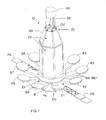
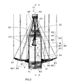
- An instrument according to the invention comprises a support (or carrier structure) SS, a deployable primary reflector, a secondary reflector RS, possibly deployable, and acquisition means MA (see FIG. figure 2 ).
- acquisition means here means all the elements that intervene in the data acquisition chain downstream of the secondary reflector RS. They thus group together the means of collection of the electromagnetic waves (or sensors) M, the combination of reflective surfaces, which is used to convey the electromagnetic waves reflected by the secondary reflector RS towards the collection focal plane (or detection) where are located the collection means M, the data processing means MT and the possible storage memory MY.
- the support SS is a structure of axial type, that is to say having a longitudinal extension along an axis XX greater than its transverse extension in a plane perpendicular to the axis XX, which is limited by the internal diameter of the CO cap of the rocket (or launcher).
- This support SS is at least partially hollow in order to define a reception zone Z3 in which is housed at least a part of the acquisition means MA.
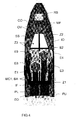
- the support SS has a cross-sectional view (see figure 3 ) a general shape of hexagonal type. This form is advantageous because it gives the support a high mechanical stability. But, any other form can be considered.
- the support SS is (intended to be) secured to a support platform PL of the observation satellite EO, to which are for example also secured solar panels (see figure 1 ).
- the primary reflector consists of at least two deployable reflective elements Ei which, when deployed in a final position, together define a reflecting surface.
- the nine elements Ei are intended, once deployed in their final position, to be placed on the periphery of the support SS, substantially equidistant from each other. But, this is not mandatory.
- the elements Ei of the primary reflector are charged mirrors, once deployed in their final position, to reflect photons (electromagnetic wave quantization) in the direction of the secondary reflector RS.
- the elements Ei can be of any form. Moreover, the elements Ei are not all necessarily identical, nor necessarily placed in the final position at the same distance from the axis XX.
- the primary reflector consists of non-joined elements Ei (once deployed), as is the case in the nonlimiting example illustrated on the Figures 1 to 4 it has a so-called "diluted" configuration.
- the elements Ei of the primary reflector are coupled to the support SS, at a first zone Z1, via a first mechanism MC1, here partially materialized by articulated arms BA (for example).
- This first mechanism MC1 can be partially housed in the support SS, or, as illustrated on the figures 1 and 2 it can be secured to the periphery of the support SS, for example via an interface IF such as a structural ring.
- the first coupling zone Z1 is for example located, as illustrated, at a first end of the support SS. But this is not obligatory.
- the first mechanism MC1 is responsible for deploying the elements Ei of the primary reflector between a folded initial position (materialized on the figures 3 and 4 ) and the final position deployed (materialized on the figures 1 and 2 ).
- the first mechanism MC1 is responsible for maintaining before deployment elements Ei in an initial position in which they are folded towards the support SS.
- the reflective faces of the elements Ei are all oriented towards the support SS. But, this is not mandatory. Indeed, these reflective faces may also be oriented towards the outside, or some reflecting faces may be oriented towards the support SS and some others to the outside. It can even be envisaged that some reflecting faces are initially placed obliquely. In the illustrated example, in the initial position (folded) the nine elements Ei are placed near the support SS on two different levels.
- the elements E2, E4, E6 and E8 are placed at a higher level and the elements E1, E3, E5, E7 and E9 are placed at a lower level, because of the impossibility of storing all the elements Ei on the same level because of their dimensions.
- certain elements Ei are initially placed against the support SS by means of articulated arms BA oriented towards the top of the support SS, whereas the other elements Ei are placed against the platform PL by means of articulated arms BA downwards.
- the first mechanism MC1 may for example be responsible for maintaining after deployment the elements Ei in a final position in which they are spaced radially from the support SS (and therefore the axis XX), their reflecting faces then being oriented towards the reflector secondary RS.
- the articulated arms BA which support the elements Ei can for example start by radially spreading the elements Ei of the support SS, by rotation, then they position the elements Ei in their final position, by translation. Any other first mechanism MC1 can be considered, regardless of the number of degrees of freedom.
- the first mechanism MC1 may comprise arms having one or more joints.
- the secondary reflector RS consists of at least one reflecting element charged with reflecting the electromagnetic waves (here photons) coming from the primary reflector towards the acquisition means MA.
- this element is a mirror.
- the secondary reflector RS is coupled to the support SS at a second zone Z2 remote from the first zone Z1.
- This second coupling zone Z2 is for example located, as illustrated, at a second end of the support SS. But this is not obligatory.
- This secondary reflector RS can be fixedly secured to the support SS via an attachment means MF (for example consisting of rigid arms as shown in the figures). It is then constantly placed in a fixed position with respect to the means M for collecting the electromagnetic waves of the acquisition means MA, that is to say during and after the launch phase (or transport in space).
- an attachment means MF for example consisting of rigid arms as shown in the figures.
- the instrument IO may comprise a second mechanism (not shown) secured to the support SS and the secondary reflector RS, and responsible for moving (or even deploying) the latter between a initial position and an extended end position in which it is placed in a fixed position relative to the collection means of the acquisition means MA.
- This second mechanism may be partially housed in the support SS or secured to the periphery of the latter.
- the second mechanism is loaded, on the one hand, to maintain before deployment the secondary reflector RS in an initial position in which it is placed against the second end of the support SS (or within it). ci), and secondly, to bring it during deployment in a final position remote from the support SS to maintain it.
- the acquisition means MA are housed at least partially inside the support SS, for example between its first Z1 and second Z2 zones (end) where are respectively coupled the main reflector and the secondary reflector RS .
- This positioning inside the support SS makes it possible to considerably reduce the bulk of the combination of reflective surfaces MO, which is used to convey the electromagnetic waves reflected by the secondary reflector RS towards the collection focal plane (or detection) where located the collection means M, and reduce the size of the elements of the combination of reflective surfaces MO. This results in a gain in volume and mass which facilitates the setting in orbit of the instrument IO when its main reflector must have a (very) large diameter once deployed.
- the latter comprises in its second zone Z2 an OV opening of dimension adapted to the needs.
- acquisition means MA Any type of acquisition means MA may be considered, depending on the application.
- the acquisition means MA which are installed in the support SS comprise at least a part of the combination of reflective surfaces MO, materialized on the figure 2 , by way of nonlimiting example, by three reflecting mirrors M1, M2 and M3 (of any type). These mirror mirrors M1, M2 and M3 are responsible for sending at the level of the focal plane of collection (or detection), where are placed the collection means M, the electromagnetic waves (here photons) which have been reflected by the secondary receiver RS.
- the collection means M for example sensors (here photonic), are also housed in the support SS.
- the processing means MT which are responsible for converting the signals delivered by the sensors M into data, for example digital, can also be accommodated in the medium SS.
- the possible data storage memory MY which may be provided for storing the data delivered by the processing means MT.
- processing means MT and the possible memory MY may be installed in a place of the spacecraft EO which is remote from the support SS, for example because of thermal stresses, or even on another spacecraft in the case of a formation flight.
- the IO instrument is a telescope with optical aperture synthesis, Korsch type. It comprises in addition to the primary and secondary reflectors RS, complementary optical means (or elements with reflective surfaces) MO, consisting of three reflecting mirrors M1 to M3.
- the first reflecting mirror M1 is responsible for reflecting towards the second reflecting mirror M2 the photons reflected by the secondary reflector RS.
- the second reflecting mirror M2 is responsible for reflecting to the third reflecting mirror M3 the photons reflected by the first reflecting mirror M1.
- the third reflecting mirror M3 (of plane type) is responsible for reflecting towards the collection means M the photons reflected by the second reflecting mirror M2.
- the arrangement presented above is particularly advantageous because it allows to have the axis of view of the IO telescope parallel to the launch axis of the spacecraft EO, which is favorable mechanically at the time of firing. In addition, it offers a mode of attachment of the RS secondary reflector very stable mechanically.
- the entirety of the acquisition means (combination of reflective surfaces, means of collection in the focal plane, data processing means and memory of storage) is housed in the support of the primary and secondary reflectors.
- the invention is not limited to this embodiment. It concerns indeed all the embodiments in which the support houses at least part of the acquisition means, and in particular at least part of the combination of reflecting surfaces, which forms part of these acquisition means, and the means of collection. Therefore, the support can accommodate all or part of the combination of reflecting surfaces, as well as the collection means and possibly the associated additional means (data processing means and storage memory).
Landscapes
- Physics & Mathematics (AREA)
- Engineering & Computer Science (AREA)
- Remote Sensing (AREA)
- Astronomy & Astrophysics (AREA)
- General Physics & Mathematics (AREA)
- Aviation & Aerospace Engineering (AREA)
- Optics & Photonics (AREA)
- Life Sciences & Earth Sciences (AREA)
- Sustainable Development (AREA)
- Electromagnetism (AREA)
- Aerials With Secondary Devices (AREA)
- Telescopes (AREA)
Applications Claiming Priority (2)
| Application Number | Priority Date | Filing Date | Title |
|---|---|---|---|
| FR0653701A FR2905804B1 (fr) | 2006-09-13 | 2006-09-13 | Instrument d'acquisition spatiale a reflecteur(s) deployable(s) et a compacite elevee |
| PCT/EP2007/059541 WO2008031826A1 (fr) | 2006-09-13 | 2007-09-11 | Instrument d'acquisition spatiale a reflecteur(s) deployable(s) et a compacite elevee |
Publications (2)
| Publication Number | Publication Date |
|---|---|
| EP2062328A1 EP2062328A1 (fr) | 2009-05-27 |
| EP2062328B1 true EP2062328B1 (fr) | 2014-07-16 |
Family
ID=37908089
Family Applications (1)
| Application Number | Title | Priority Date | Filing Date |
|---|---|---|---|
| EP07803405.5A Active EP2062328B1 (fr) | 2006-09-13 | 2007-09-11 | Instrument d'acquisition spatiale a reflecteur(s) deployable(s) et a compacite elevee |
Country Status (4)
| Country | Link |
|---|---|
| EP (1) | EP2062328B1 (es) |
| ES (1) | ES2501442T3 (es) |
| FR (1) | FR2905804B1 (es) |
| WO (1) | WO2008031826A1 (es) |
Families Citing this family (3)
| Publication number | Priority date | Publication date | Assignee | Title |
|---|---|---|---|---|
| JP5276952B2 (ja) * | 2008-11-05 | 2013-08-28 | サカセ・アドテック株式会社 | 伸展構造物 |
| US20230194849A1 (en) * | 2021-08-02 | 2023-06-22 | Arizona Board Of Regents On Behalf Of The University Of Arizona | Versatile space telescope for quantum key distribution |
| CN113589517B (zh) * | 2021-08-11 | 2023-05-02 | 哈尔滨工业大学 | 大型太空望远镜可分离模块化子镜结构与在轨更换方法 |
Family Cites Families (4)
| Publication number | Priority date | Publication date | Assignee | Title |
|---|---|---|---|---|
| US3540048A (en) * | 1966-10-19 | 1970-11-10 | Nasa | Deep space-monitor communication satellite system |
| US5255006A (en) * | 1991-08-29 | 1993-10-19 | Space Systems/Loral, Inc. | Collapsible apparatus for forming a dish shaped surface |
| JP3763428B2 (ja) * | 1996-05-21 | 2006-04-05 | 三菱電機株式会社 | 複反射鏡アンテナ装置 |
| US6768582B1 (en) * | 2002-08-09 | 2004-07-27 | Goodrich Corporation | System for deploying the petals of a sectored mirror of an optical space telescope |
-
2006
- 2006-09-13 FR FR0653701A patent/FR2905804B1/fr not_active Expired - Fee Related
-
2007
- 2007-09-11 WO PCT/EP2007/059541 patent/WO2008031826A1/fr active Application Filing
- 2007-09-11 ES ES07803405.5T patent/ES2501442T3/es active Active
- 2007-09-11 EP EP07803405.5A patent/EP2062328B1/fr active Active
Also Published As
| Publication number | Publication date |
|---|---|
| ES2501442T3 (es) | 2014-10-01 |
| WO2008031826A1 (fr) | 2008-03-20 |
| EP2062328A1 (fr) | 2009-05-27 |
| FR2905804B1 (fr) | 2010-10-22 |
| FR2905804A1 (fr) | 2008-03-14 |
Similar Documents
| Publication | Publication Date | Title |
|---|---|---|
| EP3313734B1 (fr) | Satellite à corps principal cylindrique, empilement comprenant un tel satellite et ensemble de lancement pour un tel satellite | |
| EP2716549B1 (fr) | Satellite à modules de charge utile déployables | |
| EP1676776B1 (fr) | Dispositif de support d'éléments d'un équipement spatial, à lames flexibles déployables | |
| EP2468629B1 (fr) | Grandes structures rigides déployables | |
| EP3174794B2 (fr) | Satellite comprenant un instrument optique de prise de vue | |
| EP2468630B1 (fr) | Structure deployable formant une antenne equipee d'un generateur solaire pour un satellite | |
| EP2758310B1 (fr) | Baie propulsive | |
| EP2429900B1 (fr) | Systeme comportant une sonde spatiale mere formant un vehicule spatial porteur et une pluralite de sondes spatiales filles | |
| FR2974348A1 (fr) | Dispositif de protection d'un instrument optique d'un satellite | |
| FR2746365A1 (fr) | Perfectionnements aux satellites d'observation ou de telecommunication | |
| EP2983991A1 (fr) | Système de satellites comportant deux satellites fixés l'un à l'autre et procédé pour leur mise en orbite | |
| EP2062328B1 (fr) | Instrument d'acquisition spatiale a reflecteur(s) deployable(s) et a compacite elevee | |
| EP3259188B1 (fr) | Satellite artificiel | |
| CA3141789C (fr) | Vehicule spatial, lanceur et empilement de vehicules spatiaux | |
| FR2780819A1 (fr) | Reflecteur d'antenne elastiquement deformable pour engin spatial | |
| FR2728229A1 (fr) | Bouclier de freinage pour engin spatial et satellite ainsi equipe | |
| EP3959141B1 (fr) | Structure déployable de grande dimension | |
| WO2007028923A1 (fr) | Reflecteur deployable en forme de triangle de reuleaux, pour un instrument d'observation spatiale | |
| FR2972859A1 (fr) | Dispositif de commutation de reflecteurs pour une antenne a faisceau commutable | |
| FR2746364A1 (fr) | Satellite d'observation radar ou de telecommunication |
Legal Events
| Date | Code | Title | Description |
|---|---|---|---|
| PUAI | Public reference made under article 153(3) epc to a published international application that has entered the european phase |
Free format text: ORIGINAL CODE: 0009012 |
|
| 17P | Request for examination filed |
Effective date: 20090303 |
|
| AK | Designated contracting states |
Kind code of ref document: A1 Designated state(s): AT BE BG CH CY CZ DE DK EE ES FI FR GB GR HU IE IS IT LI LT LU LV MC MT NL PL PT RO SE SI SK TR |
|
| AX | Request for extension of the european patent |
Extension state: AL BA HR MK RS |
|
| 17Q | First examination report despatched |
Effective date: 20100330 |
|
| DAX | Request for extension of the european patent (deleted) | ||
| REG | Reference to a national code |
Ref country code: DE Ref legal event code: R079 Ref document number: 602007037672 Country of ref document: DE Free format text: PREVIOUS MAIN CLASS: H01Q0001280000 Ipc: B64G0001100000 |
|
| GRAP | Despatch of communication of intention to grant a patent |
Free format text: ORIGINAL CODE: EPIDOSNIGR1 |
|
| RIC1 | Information provided on ipc code assigned before grant |
Ipc: B64G 1/66 20060101ALI20140213BHEP Ipc: B64G 1/22 20060101ALI20140213BHEP Ipc: H01Q 15/16 20060101ALI20140213BHEP Ipc: G02B 23/06 20060101ALI20140213BHEP Ipc: H01Q 1/28 20060101ALI20140213BHEP Ipc: H01Q 19/19 20060101ALI20140213BHEP Ipc: G02B 7/183 20060101ALI20140213BHEP Ipc: B64G 1/10 20060101AFI20140213BHEP |
|
| INTG | Intention to grant announced |
Effective date: 20140303 |
|
| GRAS | Grant fee paid |
Free format text: ORIGINAL CODE: EPIDOSNIGR3 |
|
| GRAA | (expected) grant |
Free format text: ORIGINAL CODE: 0009210 |
|
| AK | Designated contracting states |
Kind code of ref document: B1 Designated state(s): AT BE BG CH CY CZ DE DK EE ES FI FR GB GR HU IE IS IT LI LT LU LV MC MT NL PL PT RO SE SI SK TR |
|
| REG | Reference to a national code |
Ref country code: GB Ref legal event code: FG4D Free format text: NOT ENGLISH |
|
| REG | Reference to a national code |
Ref country code: CH Ref legal event code: EP |
|
| REG | Reference to a national code |
Ref country code: IE Ref legal event code: FG4D Free format text: LANGUAGE OF EP DOCUMENT: FRENCH |
|
| REG | Reference to a national code |
Ref country code: AT Ref legal event code: REF Ref document number: 677450 Country of ref document: AT Kind code of ref document: T Effective date: 20140815 |
|
| REG | Reference to a national code |
Ref country code: DE Ref legal event code: R096 Ref document number: 602007037672 Country of ref document: DE Effective date: 20140821 |
|
| REG | Reference to a national code |
Ref country code: ES Ref legal event code: FG2A Ref document number: 2501442 Country of ref document: ES Kind code of ref document: T3 Effective date: 20141001 |
|
| REG | Reference to a national code |
Ref country code: NL Ref legal event code: VDEP Effective date: 20140716 |
|
| REG | Reference to a national code |
Ref country code: AT Ref legal event code: MK05 Ref document number: 677450 Country of ref document: AT Kind code of ref document: T Effective date: 20140716 |
|
| REG | Reference to a national code |
Ref country code: LT Ref legal event code: MG4D |
|
| PG25 | Lapsed in a contracting state [announced via postgrant information from national office to epo] |
Ref country code: PT Free format text: LAPSE BECAUSE OF FAILURE TO SUBMIT A TRANSLATION OF THE DESCRIPTION OR TO PAY THE FEE WITHIN THE PRESCRIBED TIME-LIMIT Effective date: 20141117 Ref country code: GR Free format text: LAPSE BECAUSE OF FAILURE TO SUBMIT A TRANSLATION OF THE DESCRIPTION OR TO PAY THE FEE WITHIN THE PRESCRIBED TIME-LIMIT Effective date: 20141017 Ref country code: FI Free format text: LAPSE BECAUSE OF FAILURE TO SUBMIT A TRANSLATION OF THE DESCRIPTION OR TO PAY THE FEE WITHIN THE PRESCRIBED TIME-LIMIT Effective date: 20140716 Ref country code: LT Free format text: LAPSE BECAUSE OF FAILURE TO SUBMIT A TRANSLATION OF THE DESCRIPTION OR TO PAY THE FEE WITHIN THE PRESCRIBED TIME-LIMIT Effective date: 20140716 Ref country code: BG Free format text: LAPSE BECAUSE OF FAILURE TO SUBMIT A TRANSLATION OF THE DESCRIPTION OR TO PAY THE FEE WITHIN THE PRESCRIBED TIME-LIMIT Effective date: 20141016 Ref country code: SE Free format text: LAPSE BECAUSE OF FAILURE TO SUBMIT A TRANSLATION OF THE DESCRIPTION OR TO PAY THE FEE WITHIN THE PRESCRIBED TIME-LIMIT Effective date: 20140716 |
|
| PG25 | Lapsed in a contracting state [announced via postgrant information from national office to epo] |
Ref country code: AT Free format text: LAPSE BECAUSE OF FAILURE TO SUBMIT A TRANSLATION OF THE DESCRIPTION OR TO PAY THE FEE WITHIN THE PRESCRIBED TIME-LIMIT Effective date: 20140716 Ref country code: IS Free format text: LAPSE BECAUSE OF FAILURE TO SUBMIT A TRANSLATION OF THE DESCRIPTION OR TO PAY THE FEE WITHIN THE PRESCRIBED TIME-LIMIT Effective date: 20141116 Ref country code: NL Free format text: LAPSE BECAUSE OF FAILURE TO SUBMIT A TRANSLATION OF THE DESCRIPTION OR TO PAY THE FEE WITHIN THE PRESCRIBED TIME-LIMIT Effective date: 20140716 Ref country code: LV Free format text: LAPSE BECAUSE OF FAILURE TO SUBMIT A TRANSLATION OF THE DESCRIPTION OR TO PAY THE FEE WITHIN THE PRESCRIBED TIME-LIMIT Effective date: 20140716 Ref country code: CY Free format text: LAPSE BECAUSE OF FAILURE TO SUBMIT A TRANSLATION OF THE DESCRIPTION OR TO PAY THE FEE WITHIN THE PRESCRIBED TIME-LIMIT Effective date: 20140716 Ref country code: PL Free format text: LAPSE BECAUSE OF FAILURE TO SUBMIT A TRANSLATION OF THE DESCRIPTION OR TO PAY THE FEE WITHIN THE PRESCRIBED TIME-LIMIT Effective date: 20140716 |
|
| REG | Reference to a national code |
Ref country code: DE Ref legal event code: R097 Ref document number: 602007037672 Country of ref document: DE |
|
| PG25 | Lapsed in a contracting state [announced via postgrant information from national office to epo] |
Ref country code: RO Free format text: LAPSE BECAUSE OF FAILURE TO SUBMIT A TRANSLATION OF THE DESCRIPTION OR TO PAY THE FEE WITHIN THE PRESCRIBED TIME-LIMIT Effective date: 20140716 Ref country code: DK Free format text: LAPSE BECAUSE OF FAILURE TO SUBMIT A TRANSLATION OF THE DESCRIPTION OR TO PAY THE FEE WITHIN THE PRESCRIBED TIME-LIMIT Effective date: 20140716 Ref country code: EE Free format text: LAPSE BECAUSE OF FAILURE TO SUBMIT A TRANSLATION OF THE DESCRIPTION OR TO PAY THE FEE WITHIN THE PRESCRIBED TIME-LIMIT Effective date: 20140716 Ref country code: SK Free format text: LAPSE BECAUSE OF FAILURE TO SUBMIT A TRANSLATION OF THE DESCRIPTION OR TO PAY THE FEE WITHIN THE PRESCRIBED TIME-LIMIT Effective date: 20140716 Ref country code: LU Free format text: LAPSE BECAUSE OF FAILURE TO SUBMIT A TRANSLATION OF THE DESCRIPTION OR TO PAY THE FEE WITHIN THE PRESCRIBED TIME-LIMIT Effective date: 20140911 Ref country code: CZ Free format text: LAPSE BECAUSE OF FAILURE TO SUBMIT A TRANSLATION OF THE DESCRIPTION OR TO PAY THE FEE WITHIN THE PRESCRIBED TIME-LIMIT Effective date: 20140716 Ref country code: MC Free format text: LAPSE BECAUSE OF FAILURE TO SUBMIT A TRANSLATION OF THE DESCRIPTION OR TO PAY THE FEE WITHIN THE PRESCRIBED TIME-LIMIT Effective date: 20140716 |
|
| REG | Reference to a national code |
Ref country code: CH Ref legal event code: PL |
|
| PLBE | No opposition filed within time limit |
Free format text: ORIGINAL CODE: 0009261 |
|
| STAA | Information on the status of an ep patent application or granted ep patent |
Free format text: STATUS: NO OPPOSITION FILED WITHIN TIME LIMIT |
|
| REG | Reference to a national code |
Ref country code: IE Ref legal event code: MM4A |
|
| 26N | No opposition filed |
Effective date: 20150417 |
|
| PG25 | Lapsed in a contracting state [announced via postgrant information from national office to epo] |
Ref country code: BE Free format text: LAPSE BECAUSE OF NON-PAYMENT OF DUE FEES Effective date: 20140930 |
|
| PG25 | Lapsed in a contracting state [announced via postgrant information from national office to epo] |
Ref country code: CH Free format text: LAPSE BECAUSE OF NON-PAYMENT OF DUE FEES Effective date: 20140930 Ref country code: LI Free format text: LAPSE BECAUSE OF NON-PAYMENT OF DUE FEES Effective date: 20140930 |
|
| PG25 | Lapsed in a contracting state [announced via postgrant information from national office to epo] |
Ref country code: IE Free format text: LAPSE BECAUSE OF NON-PAYMENT OF DUE FEES Effective date: 20140911 |
|
| PG25 | Lapsed in a contracting state [announced via postgrant information from national office to epo] |
Ref country code: SI Free format text: LAPSE BECAUSE OF FAILURE TO SUBMIT A TRANSLATION OF THE DESCRIPTION OR TO PAY THE FEE WITHIN THE PRESCRIBED TIME-LIMIT Effective date: 20140716 |
|
| PG25 | Lapsed in a contracting state [announced via postgrant information from national office to epo] |
Ref country code: MT Free format text: LAPSE BECAUSE OF FAILURE TO SUBMIT A TRANSLATION OF THE DESCRIPTION OR TO PAY THE FEE WITHIN THE PRESCRIBED TIME-LIMIT Effective date: 20140716 |
|
| PG25 | Lapsed in a contracting state [announced via postgrant information from national office to epo] |
Ref country code: TR Free format text: LAPSE BECAUSE OF FAILURE TO SUBMIT A TRANSLATION OF THE DESCRIPTION OR TO PAY THE FEE WITHIN THE PRESCRIBED TIME-LIMIT Effective date: 20140716 Ref country code: HU Free format text: LAPSE BECAUSE OF FAILURE TO SUBMIT A TRANSLATION OF THE DESCRIPTION OR TO PAY THE FEE WITHIN THE PRESCRIBED TIME-LIMIT; INVALID AB INITIO Effective date: 20070911 |
|
| REG | Reference to a national code |
Ref country code: FR Ref legal event code: PLFP Year of fee payment: 10 |
|
| REG | Reference to a national code |
Ref country code: FR Ref legal event code: PLFP Year of fee payment: 11 |
|
| REG | Reference to a national code |
Ref country code: FR Ref legal event code: PLFP Year of fee payment: 12 |
|
| PGFP | Annual fee paid to national office [announced via postgrant information from national office to epo] |
Ref country code: IT Payment date: 20230829 Year of fee payment: 17 Ref country code: GB Payment date: 20230817 Year of fee payment: 17 |
|
| PGFP | Annual fee paid to national office [announced via postgrant information from national office to epo] |
Ref country code: FR Payment date: 20230821 Year of fee payment: 17 Ref country code: DE Payment date: 20230816 Year of fee payment: 17 |
|
| PGFP | Annual fee paid to national office [announced via postgrant information from national office to epo] |
Ref country code: ES Payment date: 20231009 Year of fee payment: 17 |