EP2061257A2 - Image display apparatus and method for displaying image - Google Patents
Image display apparatus and method for displaying image Download PDFInfo
- Publication number
- EP2061257A2 EP2061257A2 EP08019681A EP08019681A EP2061257A2 EP 2061257 A2 EP2061257 A2 EP 2061257A2 EP 08019681 A EP08019681 A EP 08019681A EP 08019681 A EP08019681 A EP 08019681A EP 2061257 A2 EP2061257 A2 EP 2061257A2
- Authority
- EP
- European Patent Office
- Prior art keywords
- light
- laser light
- laser
- unit
- display apparatus
- Prior art date
- Legal status (The legal status is an assumption and is not a legal conclusion. Google has not performed a legal analysis and makes no representation as to the accuracy of the status listed.)
- Granted
Links
- 238000000034 method Methods 0.000 title claims abstract description 23
- 230000003287 optical effect Effects 0.000 claims description 13
- 230000005855 radiation Effects 0.000 claims description 4
- 230000008569 process Effects 0.000 abstract description 12
- 238000010586 diagram Methods 0.000 description 24
- 230000008859 change Effects 0.000 description 9
- 230000010287 polarization Effects 0.000 description 9
- 238000001514 detection method Methods 0.000 description 8
- 230000006870 function Effects 0.000 description 6
- 239000003086 colorant Substances 0.000 description 5
- 230000007246 mechanism Effects 0.000 description 5
- 230000004044 response Effects 0.000 description 5
- 230000000694 effects Effects 0.000 description 4
- 238000006243 chemical reaction Methods 0.000 description 2
- 230000010355 oscillation Effects 0.000 description 2
- 230000007423 decrease Effects 0.000 description 1
- 230000001747 exhibiting effect Effects 0.000 description 1
- 239000000463 material Substances 0.000 description 1
- 238000002310 reflectometry Methods 0.000 description 1
- 230000001360 synchronised effect Effects 0.000 description 1
Images









Classifications
-
- H—ELECTRICITY
- H04—ELECTRIC COMMUNICATION TECHNIQUE
- H04N—PICTORIAL COMMUNICATION, e.g. TELEVISION
- H04N9/00—Details of colour television systems
- H04N9/12—Picture reproducers
- H04N9/31—Projection devices for colour picture display, e.g. using electronic spatial light modulators [ESLM]
- H04N9/3141—Constructional details thereof
- H04N9/315—Modulator illumination systems
- H04N9/3155—Modulator illumination systems for controlling the light source
-
- H—ELECTRICITY
- H04—ELECTRIC COMMUNICATION TECHNIQUE
- H04N—PICTORIAL COMMUNICATION, e.g. TELEVISION
- H04N9/00—Details of colour television systems
- H04N9/12—Picture reproducers
- H04N9/31—Projection devices for colour picture display, e.g. using electronic spatial light modulators [ESLM]
- H04N9/3129—Projection devices for colour picture display, e.g. using electronic spatial light modulators [ESLM] scanning a light beam on the display screen
-
- H—ELECTRICITY
- H04—ELECTRIC COMMUNICATION TECHNIQUE
- H04N—PICTORIAL COMMUNICATION, e.g. TELEVISION
- H04N9/00—Details of colour television systems
- H04N9/12—Picture reproducers
- H04N9/31—Projection devices for colour picture display, e.g. using electronic spatial light modulators [ESLM]
- H04N9/3191—Testing thereof
- H04N9/3194—Testing thereof including sensor feedback
Definitions
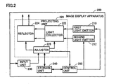
- FIG. 2 is a block diagram showing configurations of functions of image display apparatus 200.
- Image display apparatus 200 includes a first light emitter 210, a second light emitter 212, a projecting unit 220, an input unit 230, a storage unit 240, and a control unit 250.
- Projecting unit 220 includes a light collector 222, a reflector 224, and an adjuster 226.
- First light emitter 210 is configured to emit a first laser light having a certain wavelength.
- Second light emitter 212 is configured to emit a second laser light having a wavelength different from the certain wavelength.
- the laser light emitted from first light emitter 210 and second light emitter 212 enters light collector 222.
- Light collector 222 causes the laser lights to exit to reflector 224 in a certain direction.
- Storage unit 240 stores parameters (e.g., data for specifying the angle of reflector 224) that are used when adjuster 226 drives.
- storage unit 240 is configured as a non-volatile memory.
- Control unit 250 is configured to control the amounts of light emission from first light emitter 210 and second light emitter 212, based on an operation for adjusting the projection direction of the light.
- Control unit 250 is implemented as a processor or other arithmetic and control unit.
- Front-end FPGA 310 includes a data/gradation converter 314, a timing controller 311, a data controller 312, and a bit data converter 313.
- Digital signal processor 320 includes a mirror servo block 321 and a converter 322.
- red/blue LD 362 is such that a red LD and a blue LD are integrally formed, red/blue LD 362 may be separately formed.
- Data/gradation converter 314 converts the data outputted from bit data converter 313, into color gradation for displaying the data as three colors of G, R, and B and sends out the converted data to laser control circuits 351, 352, and 353.
- converter 322 transmits a signal sent from mirror servo block 321, to CPU 341.
- converter 322 generates a signal including an instruction provided to driver 373 and a state of driver 373 and sends out the signal to CPU 341.
- step S410 CPU 341 detects that power to projector 100 is turned on.
- step S412 CPU 341 first oscillates lasers at a safe level.
- step S414 CPU 341 maintains the oscillation at the safe level for a certain period of time and alerts a user of projector 100 to prevent laser lights from unexpectedly entering the eyes when a switch is turned on.
- CPU341 may gradually increase laser oscillation output to a steady-state level in a certain period of time.
- step S470 CPU 341 returns the signal values of green LD 361 and red/blue LD 362, which are controlled by laser control circuits 351, 352, and 353, to a normal level. More specifically, CPU 341 sends out an instruction to return the signal values to the normal level, to timing controller 311. Timing controller 311 transmits the instruction to data/gradation converter 314 through bit data converter 313. When data/gradation converter 314 provides signals based on the instruction respectively to laser control circuits 351, 352, and 353, the signal values are returned to the normal level. Thereafter, the laser light emitted from green LD 361 and the laser light emitted from red/blue LD 362 have normal output levels.
- the switch of projector 100 is set to ON.
- CPU 341 detects the ON, CPU 341 starts a normal light emission operation. More specifically, CPU 341 provides a light emission instruction to timing controller 311 such that the amount of the light obtains a preset steady-state level L(1). Based on the light emission instruction, timing controller 311 provides a signal for driving laser control circuits 351, 352, and 353, through bit data converter 313 and data/gradation converter 314.
- green LD 361 and red/blue LD 362 emit laser lights of the respective colors based on control of laser control circuits 351, 352, and 353, the amount of the light to be measured gradually increases. The amount of light reaches steady-state level L(1) at time t(1). The steady-state state continues from time t(1) to t(2).
- an operation for adjusting the radiation direction of the laser light is detected.
- the operation is, for example, an operation for adjusting the tilt of two-axis galvanometer mirror 372
- the operation may also include other operations for adjusting an internal mechanism.
- projector 100 detects the operation, projector 100 reduces the output levels of laser lights to a safe level. By doing so, even when a user performs an operation while projector 100 outputs laser lights, safety of the user can be maintained.
- the laser light transmitted through hologram element 652 projects spots for detecting parallelism in photodetector 654.
- Photodetector 654 adjusts the parallelism of the laser light. The adjustment is performed, for example, such that the sizes of the spots (the diameters of circles to be projected, etc.) match each other.
- projector 600 can suppress output of the laser light projected from projection lens 670 and accordingly the safety can be enhanced.
- FIG. 7 is a diagram showing an external appearance of projector 700.
- Projector 700 includes a laser exit aperture 710 and a photodetector 720. It is preferable that photodetector 720 be disposed on the same surface as the disposition surface of laser exit aperture 710. On the other hand, it is preferable that photodetector 720 be disposed at a location where the laser light radiated from laser exit aperture 710 is not directly detected.
- Laser 950 outputs the laser light according to a control signal from controller 940.
- laser 950 includes an infrared laser and two-wavelength lasers of red and blue.
- Lens 960 focuses the laser light outputted from laser 950 in a certain direction and output the laser light.
- the laser light transmitted through lens 960 is reflected by mirror 970 and projected outside projector 700 through laser exit aperture 710.
- step S 1830 the processor drives the red laser diode to radiate red laser light on the entire surface of the screen and calculates an amount of light B0 based on the detected amount of the light.
- step S 1850 the processor drives the green laser diode to radiate green laser light on the entire surface of the screen and calculates an amount of light D0 based on the detected amount of the light.
- step S1860 the processor prepares image data. More specifically, the processor reads image data (for three colors of R G, and B composing an image) used to show an image on the screen from the non-volatile memory and stores the image data in a work area of a volatile memory.
- image data for three colors of R G, and B composing an image
- step S 1870 the processor calculates a display area for each color for the case in which an image is projected for each color, and calculates assumed incremental amounts of light B1, C1, and D1.
- An image display apparatus is different from the image display apparatuses according to the foregoing embodiments in that the apparatus has a function of suppressing output of the laser light when detecting movement thereof.
- the movement includes, for example, a change in the location of the image display apparatus, an operation for adjusting the projection direction, or an operation for adjusting the size or shape of a projection surface.
- step S1320 processor 910 determines whether there has been an input from angular velocity sensor 1110. If processor 910 determines that there has been an input from angular velocity sensor 1110 (YES in step S 1320), then processor 910 returns control to step S1310. By this, laser 950 continues the laser light output at the first output level. On the other hand, if processor 910 determines that there has been no input from angular velocity sensor 1110 (NO in step S1320), then processor 910 switches control to step S1330.
- oscillating unit 1400 can be operated by a user of projector 1100 to adjust the projection direction of the laser light.
- processor 910 can detect an operation performed by the user.
Landscapes
- Engineering & Computer Science (AREA)
- Multimedia (AREA)
- Signal Processing (AREA)
- Physics & Mathematics (AREA)
- Optics & Photonics (AREA)
- Projection Apparatus (AREA)
- Transforming Electric Information Into Light Information (AREA)
- Mechanical Optical Scanning Systems (AREA)
- Control Of Indicators Other Than Cathode Ray Tubes (AREA)
Abstract
Description
- The present invention relates to an apparatus and a method for displaying an image, and more particularly, to an image display apparatus and method for projecting an image by laser light.
- As a projector that is one of image display apparatuses, a project is known. For example, Japanese Patent Laying-Open No.
2006-276446 2006-133401 2004-101622 2004-341210 - When a projector using a laser as a light source is used, there is a possibility that laser light may enter the eyes of a person. For example, according to a technique disclosed in Japanese Patent Laying-Open No.
2004-341210 - The present invention is made to solve problems such as those described above, and therefore, an object of the present invention is to provide an image display apparatus and method that can prevent the laser light from entering the eyes of a person.
- An image display apparatus according to one aspect of the present invention includes: a first light-emitting unit configured to emit a first laser light; a second light-emitting unit configured to emit a second laser light having a wavelength different from a wavelength of the first laser light; a reflecting unit disposed to reflect the first laser light and the second laser light; an input unit configured to accept an input performed on the image display apparatus; an adjusting unit configured to adjust, based on the input, a projection direction of lights reflected by the reflecting unit or a size or shape of a projection surface; and a control unit configured to control amounts of light emission from the first light-emitting unit and the second light-emitting unit, based on an operation for adjusting the projection direction of the light.
- An image display apparatus according to another aspect of the present invention includes: a light-emitting unit configured to radiate laser light; a photodetector configured to detect light; a storage unit configured to store a first amount of the light detected by the photodetector when the light-emitting unit does not radiate the laser light at a predetermined certain amount of the light, a second amount of the light detected by the photodetector when the light-emitting unit radiates the laser light, and a third amount of the light detected by the photodetector when the light-emitting unit radiates the laser light to project an image; and a control unit configured to control an operation of the image display apparatus. The control unit is configured to: calculate a fourth amount of the light at which light reception is assumed by projecting the image, based on image data based on which the image is formed, the first amount of the light, and the second amount of the light; and suppress an output of the laser light when the difference between the third amount of the light and the fourth amount of the light is greater than or equal to a preset value.
- An image display apparatus according to still another aspect of the present invention includes: a light-emitting unit configured to radiate laser light; a detecting unit configured to detect movement of the image display apparatus; and a control unit configured to control radiation by the light-emitting unit. The control unit is configured to: cause, after start-up of the image display apparatus, the light-emitting unit to output the laser light at a predetermined first level; cause the light-emitting unit to continue the output at the first level for a predetermined period of time after the start-up of the image display apparatus or while the movement of the image display apparatus is detected based on an output from the detecting unit; and raise the output by the light-emitting unit to a preset second level when the predetermined period of time has elapsed after the movement of the image display apparatus is no longer detected.
- A method for displaying an image according to yet another aspect of the present invention includes the steps of: emitting a first laser light and a second laser light having a wavelength different from a wavelength of the first laser light; adjusting a projection direction of the reflected light of the first laser light and the second laser light or a size or shape of a projection surface; and controlling amounts of the light emission of a light source of the first laser light and a light source of the second laser light based on an operation for adjusting the projection direction of the light.
- The foregoing and other objects, features, aspects and advantages of the present invention will become more apparent from the following detailed description of the present invention when taken in conjunction with the accompanying drawings.
-
-
Fig. 1 is a diagram showing a state in which aprojector 100 which is one mode of an image display apparatus according to the present invention is set up. -
Fig. 2 is a block diagram showing configurations of functions of animage display apparatus 200 according to the present invention. -
Fig. 3 is a block diagram showing a hardware configuration ofprojector 100. -
Fig. 4 is a flowchart showing a part of an operation performed by aCPU 341 included inprojector 100. -
Fig. 5 is a timing chart showing a change in the amount of light after power toprojector 100 is turned on. -
Fig. 6 is a block diagram showing a hardware configuration of aprojector 600 according to a variant of the first embodiment of the present invention. -
Fig. 7 is a diagram showing an external appearance of aprojector 700 according to a second embodiment of the present invention. -
Fig. 8 is a diagram showing a scene where a user is present betweenprojector 700 and an image projected onto a wall. -
Fig. 9 is a block diagram showing the main hardware configuration ofprojector 700. -
Fig. 10 is a flowchart showing a summary of a process performed by aprocessor 910 included inprojector 700. -
Fig. 11 is a flowchart showing a part of a process performed by a processor. -
Fig. 12 is a diagram (part 1) schematically showing a configuration of aprojector 1100 according to a third embodiment of the present invention. -
Fig. 13 is a diagram (part 2) schematically showing a configuration ofprojector 1100. -
Fig. 14 is a flowchart showing a part of the main operation performed by aprocessor 910 included inprojector 1100 according to the third embodiment of the present invention. -
Fig. 15 is a diagram showing a part of a hardware configuration ofprojector 1100. -
Fig. 16 is a diagram showing a state in which aprojector 1500 is set to an externally projectable state. -
Fig. 17 is a diagram (part 1) showing a state in which afoldable projector 1600 is folded. -
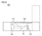
Fig. 18 is a diagram (part 2) showing a state in whichfoldable projector 1600 is folded. - With reference to the drawings, embodiments of the present invention will be described below. In the following description, the same elements are denoted by the same reference numerals. The names and functions of such elements are also the same. Thus, detailed description thereof is not repeated.
- With reference to
Fig. 1 , a use mode of an image display apparatus according to the present invention will be described.Fig. 1 is a diagram showing a state in which aprojector 100 which is one mode of an image display apparatus is set up.Projector 100 is of a portable size, for example, but may be a stationary projector. -
Projector 100 is disposed on a table 120.Projector 100 projects animage 132 for presentation onto awall 130 serving as a screen. Also,projector 100 projects animage 122 onto a top surface of table 120 so that a user ofprojector 100 can seeimage 122. The size ofimage 122 is normally smaller than that ofimage 132. In one aspect,projector 100 includes a CCD (Charge Coupled Device)sensor 110. Note thatCCD sensor 110 is not an essential configuration inprojector 100 according to the present embodiment. - With reference to
Fig. 2 , a configuration of animage display apparatus 200 according to the present invention will be described.Fig. 2 is a block diagram showing configurations of functions ofimage display apparatus 200.Image display apparatus 200 includes afirst light emitter 210, asecond light emitter 212, aprojecting unit 220, aninput unit 230, astorage unit 240, and acontrol unit 250.Projecting unit 220 includes a light collector 222, areflector 224, and anadjuster 226. -
First light emitter 210 is configured to emit a first laser light having a certain wavelength.Second light emitter 212 is configured to emit a second laser light having a wavelength different from the certain wavelength. The laser light emitted fromfirst light emitter 210 andsecond light emitter 212 enters light collector 222. Light collector 222 causes the laser lights to exit toreflector 224 in a certain direction. - Reflector 224 is configured to reflect the first laser light and the second laser light. More specifically,
reflector 224 reflects the first laser light and the second laser light toward an exit aperture (not shown) ofimage display apparatus 200. In one aspect,reflector 224 includes a galvanometer mirror. Preferably, the galvanometer mirror can adjust two axes. -
Input unit 230 is configured to accept an input of an operation performed onimage display apparatus 200. Wheninput unit 230 accepts an input of an operation,input unit 230 sends out a signal according to the input toadjuster 226. In one aspect,input unit 230 is implemented as buttons, a touch panel, or other switches. -
Adjuster 226 is configured to adjust the projection direction of the light reflected byreflector 224 or the size or shape of a projection surface, based on the input sent frominput unit 230. Note that all of the above-described items (projection direction, size, and shape) are not always included as adjustment targets, and any of the items may selectively serve as an adjustment target. In one aspect,adjuster 226 functions as an actuator configured to drivereflector 224. In one aspect,adjuster 226 includes a lens, a beam splitter that splits a first laser light and a second laser light transmitted through the lens, a hologram element disposed to receive laser light obtained through the split by the beam splitter, and a detector configured to detect light transmitted through the hologram element. At this time,control unit 250 suppresses the amount of the light emission of the laser light outputted fromfirst light emitter 210 and secondlight emitter 212, based on the drive ofreflector 224. - In another aspect,
adjuster 226 is configured to make an optical path of a first laser light substantially parallel to an optical path of a second laser light.Control unit 250 suppresses the output levels of the first laser light and the second laser light based on the drive ofadjuster 226 such as that described above. -
Storage unit 240 stores parameters (e.g., data for specifying the angle of reflector 224) that are used whenadjuster 226 drives. In one aspect,storage unit 240 is configured as a non-volatile memory. -
Control unit 250 is configured to control the amounts of light emission fromfirst light emitter 210 and secondlight emitter 212, based on an operation for adjusting the projection direction of the light.Control unit 250 is implemented as a processor or other arithmetic and control unit. - In one aspect,
control unit 250 suppresses the amounts of light emission emitted fromfirst light emitter 210 and secondlight emitter 212 to a predetermined amount of light emission or less. - In one aspect, when
control unit 250 detects an operation for adjusting the projection direction of lights,control unit 250 suppresses the amounts of light emission fromfirst light emitter 210 and secondlight emitter 212 for a predetermined period of time. - Preferably, when
control unit 250 detects completion of an operation for adjusting the projection direction of the light or the size or shape of a projection surface,control unit 250 controlsfirst light emitter 210 and secondlight emitter 212 such that the amounts of light emission fromfirst light emitter 210 and secondlight emitter 212 become those obtained before performing the adjustment operation. - Next, with reference to
Fig. 3 , a specific configuration ofprojector 100 which is an example ofimage display apparatus 200 will be described.Fig. 3 is a block diagram showing a hardware configuration ofprojector 100. -
Projector 100 includes a front-end FPGA (Field Programmable Gate Array) 310, adigital signal processor 320, anoperation panel 330, a back-end block 340, an SDRAM (Synchronous Dynamic Random Access Memory) 344, avideo RAM 345,laser control circuits blue LD 362, apolarization beam splitter 363, adetector 370, agalvanometer mirror 372, and adriver 373.Driver 373 includes, for example, a driver motor, a coil, etc. - Front-
end FPGA 310 includes a data/gradation converter 314, atiming controller 311, adata controller 312, and abit data converter 313.Digital signal processor 320 includes amirror servo block 321 and aconverter 322. Although red/blue LD 362 is such that a red LD and a blue LD are integrally formed, red/blue LD 362 may be separately formed. -
Operation panel 330 is provided on a front surface or side surface of a casing ofprojector 100.Operation panel 330 includes, for example, a display apparatus (not shown) that displays operation content; and switches (e.g., plus/minus buttons) that accept an operation input performed onprojector 100. Whenoperation panel 330 accepts an operation,operation panel 330 sends out a signal according to the operation to aCPU 341 of back-end block 340. - An image signal provided from an external source of
projector 100 is inputted to avideo interface 342. In one aspect,projector 100 includes anexternal interface 343.External interface 343 accepts, for example, a load of anSD card 380.External interface 343 reads data fromSD card 380 and the data is stored inSDRAM 344 orvideo RAM 345. -
CPU 341 controls projection of video obtained based on a signal inputted toprojector 100 throughvideo interface 342 orexternal interface 343, based on an operation input provided tooperation panel 330. More specifically, byCPU 341 performing mutual communication withtiming controller 311 of front-end FPGA 310,CPU 341 controls display of video obtained based on image data that is temporarily stored invideo RAM 345. - In front-
end FPGA 310,timing controller 311 reads data stored invideo RAM 345 throughdata controller 312 based on an instruction sent fromCPU 341.Data controller 312 sends out the read data to bitdata converter 313.Bit data converter 313 sends out the data to data/gradation converter 314 based on an instruction from timingcontroller 311.Bit data converter 313 converts image data provided from an external source, into a format that conforms to a format for projection by the laser light emission. - Data/gradation converter 314 converts the data outputted from
bit data converter 313, into color gradation for displaying the data as three colors of G, R, and B and sends out the converted data tolaser control circuits - On the other hand,
timing controller 311 controls drive of two-axis galvanometer mirror 372 withdigital signal processor 320. More specifically,timing controller 311 sends out an instruction to mirrorservo block 321 to drivedriver 373. In response to the instruction,driver 373 changes the position and tilt of two-axis galvanometer mirror 372. -
Converter 322 performs A/D (Analog to Digital) conversion of a signal sent fromCCD sensor 110, based on a signal sent from timingcontroller 311 and sends out digital data obtained after the conversion toCPU 341. For example, whenCCD sensor 110 shoots a subject present within a shootable range thereof, an image signal of the subject is sent toCPU 341. When a setting for displaying an image shot byCCD sensor 110 is valid,CPU 341 sends an instruction totiming controller 311 to display an image based on data corresponding to the image signal. - Also,
converter 322 transmits a signal sent frommirror servo block 321, toCPU 341. For example,converter 322 generates a signal including an instruction provided todriver 373 and a state ofdriver 373 and sends out the signal toCPU 341. -
Laser control circuit 351 controls drive ofgreen LD 361 based on a signal sent from data/gradation converter 314. Similarly,laser control circuits Green LD 361 and red/blue LD 362 emit laser light according to their respective control. -
Polarization beam splitter 363 is disposed on an optical path of a laser light emitted fromgreen LD 361.Polarization beam splitter 363 transmitsgreen LD 361. Also,polarization beam splitter 363 partially transmits and partially reflects red/blue LD 362.Detector 370 is disposed on optical paths of the laser light emitted from red/blue LD 362. The laser light transmitted throughpolarization beam splitter 363 is collected in a certain area through alens 371 and reflected by two-axis galvanometer mirror 372. The reflected light is projected outsideprojector 100. At this time, two-axis galvanometer mirror 372 changes the tilt thereof by drive ofdriver 373. - Next, with reference to
Fig. 4 , a control structure ofprojector 100 according to the present embodiment will be described.Fig. 4 is a flowchart showing a part of an operation performed byCPU 341 included inprojector 100. - In step S410,
CPU 341 detects that power toprojector 100 is turned on. In step S412,CPU 341 first oscillates lasers at a safe level. In step S414,CPU 341 maintains the oscillation at the safe level for a certain period of time and alerts a user ofprojector 100 to prevent laser lights from unexpectedly entering the eyes when a switch is turned on. Alternatively, CPU341 may gradually increase laser oscillation output to a steady-state level in a certain period of time. - Then, in step S420,
CPU 341 detects, based on a signal sent fromoperation panel 330, that an input for adjusting the reflection direction, etc., of two-axis galvanometer mirror 372 has been performed. At this time,CPU 341 does not need to wait for the certain period of time in step S414 to elapse and even during the process in step S414,CPU 341 can move to the process in step S420. - In step S430,
CPU 341 sends an instruction to reduce output from the lasers, to timingcontroller 311 ofFPGA 310. In step S440,CPU 341 sends an instruction totiming controller 311 to set signal values of the lasers respectively controlled bylaser control circuits - In step S450,
CPU 341 determines whether a certain period of time has elapsed since an operation input is no longer performed onoperation panel 330. IfCPU 341 determines that a certain period of time has elapsed since an operation input is no longer performed (YES in step S450), then CPU341 switches control to step S470. If not (NO in step S450), thenCPU 341 switches control to step S460. - In step S460,
CPU 341 stands by the process for a certain period of time. For example,CPU 341 suspends the process for a period of time that is pre-specified for standby. - In step S470,
CPU 341 returns the signal values ofgreen LD 361 and red/blue LD 362, which are controlled bylaser control circuits CPU 341 sends out an instruction to return the signal values to the normal level, to timingcontroller 311.Timing controller 311 transmits the instruction to data/gradation converter 314 throughbit data converter 313. When data/gradation converter 314 provides signals based on the instruction respectively tolaser control circuits green LD 361 and the laser light emitted from red/blue LD 362 have normal output levels. - With reference to
Fig. 5 , a change in the amount of the light whenprojector 100 according to the present embodiment is used will be described.Fig. 5 is a timing chart showing a change in the amount of the light after power toprojector 100 is turned on. - At
time 0, the switch ofprojector 100 is set to ON. WhenCPU 341 detects the ON,CPU 341 starts a normal light emission operation. More specifically,CPU 341 provides a light emission instruction totiming controller 311 such that the amount of the light obtains a preset steady-state level L(1). Based on the light emission instruction,timing controller 311 provides a signal for drivinglaser control circuits bit data converter 313 and data/gradation converter 314. Whengreen LD 361 and red/blue LD 362 emit laser lights of the respective colors based on control oflaser control circuits - At time t(2), a user of
projector 100 operatesoperation panel 330 to attempt to adjust the reflection direction of two-axis galvanometer mirror 372. Based on a signal fromoperation panel 330,CPU 341 detects the operation (step S420). In response to the detection,CPU 341 sends an instruction to reduce output from the lasers, to front-end FPGA 310 (step S430). -
Laser control circuits green LD 361 and red/blue LD 362 and reduce the power of the laser light to be outputted. As a result, the amount of the light detected gradually decreases from time t(2) and at time t(3) the amount of the light is reduced to an amount of the light L(2) that is a safe level. The state of the amount of the light L(2) continues for a while. The state of the amount of the light L(2) continues, for example, at least from time t(3) to time t(4). - Thereafter, when a preset safe time has elapsed from time t(4) and then time t(5) is reached,
CPU 341 provides an instruction to bring the laser output to a steady-state level, to front-end FPGA 310.Laser control circuits green LD 361 and red/blue LD 362 and thereby raise laser light output. As a result, the amount of the light detected gradually increases. At time t(6), the amount of the light reaches the amount of the light L(1) that is the steady-state level. Thereafter,projector 100 can project video at a normal amount of light. - In the above-described manner, according to
projector 100 according to the first embodiment of the present invention, an operation for adjusting the radiation direction of the laser light is detected. When the operation is, for example, an operation for adjusting the tilt of two-axis galvanometer mirror 372, the operation may also include other operations for adjusting an internal mechanism. Whenprojector 100 detects the operation,projector 100 reduces the output levels of laser lights to a safe level. By doing so, even when a user performs an operation whileprojector 100 outputs laser lights, safety of the user can be maintained. - A variant of the embodiment of the present invention will be described below. A
projector 600 according to the present variant is different fromprojector 100 according to the foregoing embodiment in thatprojector 600 has a function of adjusting the amount of the light while adjusting the parallelism of the laser light of respective colors. - With reference to
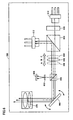
Fig. 6 , a specific configuration ofprojector 600 according to the present variant will be described.Fig. 6 is a block diagram showing a hardware configuration ofprojector 600.Projector 600 includes aninfrared laser 610, a two-wavelength laser 612, a second-harmonic generator 620, apolarization beam splitter 630, acollimate lens 642, abeam splitter 650, ahologram element 652, aphotodetector 654, a two-axis galvanometer mirror 660, and aprojection lens 670. Note thatcollimate lenses Fig. 6 show collimate lens 642 being moved from a position B to a position A or position C for focus adjustment. In the present variant, whenprojector 600 is in an initial state, the position B corresponds to an initial position ofcollimate lens 642. - A laser light outputted from
infrared laser 610 enterspolarization beam splitter 630 through second-harmonic generator 620. On the other hand, when red and blue laser light outputted from two-wavelength laser 612 enterpolarization beam splitter 630, the red and blue laser light is reflected bypolarization beam splitter 630 so as to be parallel to the laser light emitted frominfrared laser 610. Each laser light enterscollimate lens 642. - The laser light transmitted through
collimate lens 642 entersbeam splitter 650.Beam splitter 650 reflects the laser light outputted from two-wavelength laser 612 towardhologram element 652.Hologram element 652 is configured, for example, such that a pattern exhibiting a lens effect is decentered, whereby a convex lens effect occurs with + primary light and a concave lens effect occurs with - primary light and thus light spots are formed at different locations. - The laser light transmitted through
hologram element 652 projects spots for detecting parallelism inphotodetector 654.Photodetector 654 adjusts the parallelism of the laser light. The adjustment is performed, for example, such that the sizes of the spots (the diameters of circles to be projected, etc.) match each other. - On the other hand, the laser light transmitted through
beam splitter 650 is reflected by two-axis galvanometer mirror 660. The reflected light entersprojection lens 670. - In such a configuration, the output level of each laser light can be suppressed based on a detection result obtained by
photodetector 654. Specifically, a controller (not shown) included inprojector 600 detects, based on a signal fromphotodetector 654, that an operation for adjusting the parallelism of the laser light is performed. The signal is outputted in response to an operation performed on a switch ofprojector 600. Based on the detection, the controller provides an instruction to reduce the laser light output to a safe level L(2) such as that described in the first embodiment, toinfrared laser 610 and two-wavelength laser 612. - As a result, when an adjustment for the parallelism of the laser light is made by a user of
projector 600,projector 600 can suppress output of the laser light projected fromprojection lens 670 and accordingly the safety can be enhanced. - Next, a second embodiment of the present invention will be described. An image display apparatus according to the present embodiment is different from the image display apparatus according to the foregoing first embodiment in that the apparatus can suppress output when a person is detected between the apparatus and a projected image.
- With reference to
Fig. 7 , a configuration of aprojector 700 according to the second embodiment of the present invention will be described.Fig. 7 is a diagram showing an external appearance ofprojector 700.Projector 700 includes alaser exit aperture 710 and aphotodetector 720. It is preferable thatphotodetector 720 be disposed on the same surface as the disposition surface oflaser exit aperture 710. On the other hand, it is preferable thatphotodetector 720 be disposed at a location where the laser light radiated fromlaser exit aperture 710 is not directly detected. - With reference to
Fig. 8 , a use mode ofprojector 700 according to the present embodiment will be described.Fig. 8 is a diagram showing a scene where a user is present betweenprojector 700 and an image projected onto a wall.Projector 700 is projecting animage 810 onto a screen. Normally, it is not desirable that a person be present betweenprojector 700 andimage 810 but here it is assumed that aperson 820 is present in such an area. In this case,projector 700 detects, byphotodetector 720, a change in the amount of the light on a projection surface and suppresses the laser light output according to the change. - With reference to
Fig. 9 , a specific configuration ofprojector 700 according to the second embodiment of the present invention will be described.Fig. 9 is a block diagram showing a main hardware configuration ofprojector 700. -
Projector 700 includes aprocessor 910, amemory 930, acontroller 940, alaser 950, alens 960, and amirror 970, in addition tolaser exit aperture 710 andphotodetector 720.Photodetector 720 detects an amount of the light on a projection surface ofprojector 700. A result of the detection is sent toprocessor 910. -
Processor 910 controls an operation ofprojector 700 based on a signal provided from an external source or when a preset condition is satisfied. In one aspect,processor 910 controls the light emission bylaser 950, based on a detection result of an amount of the light sent fromphotodetector 720. - More specifically,
processor 910 determines whether an output level change bylaser 950 is required, based on a comparison of data that is stored in advance inmemory 930 with data representing an amount of the light sent fromphotodetector 720. For example, when a detected amount of the light is smaller than a first amount of the light that is stored in advance inmemory 930 as a setting value, there is a possibility that a person may be present in front of the screen. In this case,processor 910 determines that there is a person on optical path of the laser light and thus provides an instruction to reduce output fromlaser 950, tocontroller 940. - Alternatively, there may be a case in which a detected amount of the light is larger than a second amount of the light that is stored in advance in
memory 930 as a setting value. In this case, it can be considered that there is a person near the laser exit aperture. In this case, too,processor 910 provides an instruction to reduce output fromlaser 950, tocontroller 940. -
Controller 940 controls drive oflaser 950 based on an instruction sent fromprocessor 910. The levels of drive controlled bycontroller 940 include, for example, a normal level and a level lower than normal. -
Laser 950 outputs the laser light according to a control signal fromcontroller 940. In one aspect,laser 950 includes an infrared laser and two-wavelength lasers of red and blue. -
Lens 960 focuses the laser light outputted fromlaser 950 in a certain direction and output the laser light. The laser light transmitted throughlens 960 is reflected bymirror 970 and projected outsideprojector 700 throughlaser exit aperture 710. - Next, with reference to
Fig. 10 , a control structure ofprojector 700 will be described.Fig. 10 is a flowchart showing a schematic process performed byprocessor 910. - In step S1010,
processor 910 ofprojector 700 detects, usingphotodetector 720, an amount of light aroundprojector 700 in a state in which the laser light is not emitted fromlaser 950, and saves the detected amount of the light (first amount of light) inmemory 930. - In step S1020,
processor 910 causeslaser 950 to emit the laser light to project a white screen, detects an amount of thelight using photodetector 720, and saves the detected amount of the light (hereinafter, the second amount of light) inmemory 930. - In step S1030,
processor 910 projects an actual image, detects an amount of the light obtained at thattime using photodetector 720, and saves the detected amount of the light (hereinafter, the third amount of light) inmemory 930. - In step S1040,
processor 910 calculates an amount of the light (hereinafter, the fourth amount of light) at which light reception is assumed, from image data for displaying the image, the first amount of the light, and the second amount of the light. - In step S1050,
processor 910 determines whether the difference between the third amount of the light and the fourth amount of the light is greater than or equal to a preset value. Ifprocessor 910 determines that the difference between the third amount of the light and the fourth amount of the light is greater than or equal to a preset value (YES in step S1050), thenprocessor 910 switches control to step S 1060. If not (NO in step S1050), thenprocessor 910 returns control to step S1030. - In step S1060,
processor 910 sends out an instruction to reduce the laser light output fromlaser 950 to a preset certain value, tocontroller 940. Alternatively,processor 910 instructscontroller 940 to stop the output fromlaser 950. Thereafter,laser 950 emits the light in a mode in which the output is reduced to the certain value, or stops laser light output itself. - Now, with reference to
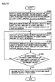
Fig. 11 , estimation of the amount of the light reception by the projectors according to the embodiments of the present invention will be described.Fig. 11 is a flowchart showing a part of a process performed by a processor included in each projector. - In step S1810, the processor detects start-up of the projector. At this point, the laser diodes (LDs) remain off.
- In step S 1820, the processor reads, through a photoreceiver, a light reception intensity (amount of light A) obtained before driving the laser diodes. By this, the amount of the light of a projector setup environment before the laser light is radiated is measured.
- In step S 1830, the processor drives the red laser diode to radiate red laser light on the entire surface of the screen and calculates an amount of light B0 based on the detected amount of the light. In this case, the processor calculates the amount of light B0 using, for example, the equation "amount of light B0 = detected amount - amount of light A".
- In step S 1840, the processor drives the blue laser diode to radiate blue laser light on the entire surface of the screen and calculates an amount of light C0 based on a detected amount of the light. In this case, the processor calculates the amount of light C0 using, for example, the equation "amount of light C0 = detected amount - amount of light A".
- In
step S 1850, the processor drives the green laser diode to radiate green laser light on the entire surface of the screen and calculates an amount of light D0 based on the detected amount of the light. In this case, the processor calculates the amount of light D0 using, for example, the equation "amount of light D0 = detected amount - amount of light A". Note that the order of steps S 1830 toS 1850 is not limited to that described above. - In step S1860, the processor prepares image data. More specifically, the processor reads image data (for three colors of R G, and B composing an image) used to show an image on the screen from the non-volatile memory and stores the image data in a work area of a volatile memory.
- In step S 1870, the processor calculates a display area for each color for the case in which an image is projected for each color, and calculates assumed incremental amounts of light B1, C1, and D1. The calculation of display areas is performed based on the brightnesses of the respective colors composing the image. For example, the processor calculates the assumed incremental amount of light B1 using equation "B1 = amount of light B0 × display area for red". Also, the processor calculates the assumed incremental amount of light C1 using equation "C1 = amount of light C0 × display area for blue". The processor calculates the assumed incremental amount of light D1 using equation "D1 = amount of light D0 × display area for green".
- In step S 1880, the processor compares the total sum of the amount of light A and the assumed amounts of B1, C1, and D1 with the amount of the light actually detected. Then, if the ratio of the total sum to the detected amount of the light is within the range of a preset value α, then the processor determines that there is no obstacle. In this case, the projector continues radiation of laser lights. On the other hand, if the processor determines that the ratio is not within the range of the preset value, then the processor determines that there is an obstacle. In this case, the processor reduces the output levels of the laser light to a preset level or temporarily stops the laser light output itself.
- In the above-described manner,
projector 700 according to the second embodiment of the present invention detects the presence of a person on the optical path of the laser light according to the detected amount of light. When the presence of a person is detected, the laser light is suppressed to minimum output (e.g., several lumens). By this, the eyes of a person present nearprojector 700 can be protected. - A process in
Fig. 10 performed byprocessor 910 includes projection of a white screen onto the entire surface and saving of an amount of light inmemory 930 in step S 1020. Some screen surfaces may have a color filter effect or may partially have different reflectivities. Therefore, by dividing the process in step S1020, an amount of light may be stored inmemory 930 for each color of RGB or the screen may be divided into multiple areas to radiate the laser light on the areas in turn and save amounts of the light inmemory 930, whereby determination accuracy can be increased when performing a comparison upon actual projection. - Next, a third embodiment of the present invention will be described. An image display apparatus according to the present embodiment is different from the image display apparatuses according to the foregoing embodiments in that the apparatus has a function of suppressing output of the laser light when detecting movement thereof. The movement includes, for example, a change in the location of the image display apparatus, an operation for adjusting the projection direction, or an operation for adjusting the size or shape of a projection surface.
- With reference to
Figs. 12 and13 , a configuration of aprojector 1100 which is one mode of the image display apparatus according to the third embodiment of the present invention will be described.Fig. 12 is a diagram schematically showingprojector 1100.Projector 1100 includes anangular velocity sensor 1110 and alaser exit aperture 1120. - With reference to
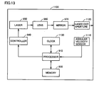
Fig. 13 ,projector 1100 includes aprocessor 910, amemory 930, aclock 1130, acontroller 940, alaser 950, alens 960, and amirror 970, in addition toangular velocity sensor 1110 andlaser exit aperture 1120. -
Angular velocity sensor 1110 detects movement ofprojector 1100 and sends out a result of the detection toprocessor 910.Processor 910 controls the operation ofprojector 1100 according to an output fromangular velocity sensor 1110.Clock 1130 measures time inprojector 1100.Processor 910 switches the mode of laser light output fromlaser 950, based on time information sent fromclock 1130 and an output fromangular velocity sensor 1110. - Next, with reference to
Fig. 14 , a control structure ofprojector 1100 according to the third embodiment of the present invention will be described.Fig. 14 is a flowchart showing a part of the main operation performed byprocessor 910. - In step S 1310,
processor 910 causeslaser 950 to output laser light at a pre-specified first output level. The first level is specified, for example, to provide a minimum amount of the light at which a projection location, focus, etc., can be checked. - In step S1320,
processor 910 determines whether there has been an input fromangular velocity sensor 1110. Ifprocessor 910 determines that there has been an input from angular velocity sensor 1110 (YES in step S 1320), thenprocessor 910 returns control to step S1310. By this,laser 950 continues the laser light output at the first output level. On the other hand, ifprocessor 910 determines that there has been no input from angular velocity sensor 1110 (NO in step S1320), thenprocessor 910 switches control to step S1330. - In step S1330,
processor 910 causes the output fromlaser 950 to be maintained at the first output level for a predetermined certain period of time, using time information sent fromclock 1130. - In step S 1340,
processor 910 increases the output fromlaser 950 to a second output level for a preset second certain period of time, based on time data sent fromclock 1130. - With reference to
FIG. 15 , a detailed configuration ofprojector 1100 will be described.Fig. 15 is a diagram showing a part of a hardware configuration ofprojector 1100. -
Projector 1100 includes anoscillating unit 1400, aprism 1410, a two-axis galvanometer mirror 1420, amirror 1440, acollimate lens 1450, abeam splitter 1460, a red/blue laser 1470, and agreen laser 1480. Laser light outputted from red/blue laser 1470 andgreen laser 1480 passes throughbeam splitter 1460 andcollimate lens 1440 and then is reflected bymirror 1440. The reflected light is reflected by two-axis galvanometer mirror 1420. The reflected light passes throughprism 1410 and is polarized and outputted. - In such a configuration, oscillating
unit 1400 can be operated by a user ofprojector 1100 to adjust the projection direction of the laser light. Hence, by providing anangle sensor 1110 inside oscillatingunit 1400,processor 910 can detect an operation performed by the user. - A fourth embodiment of the present invention will be described below. An image display apparatus according to the present embodiment has a mechanism for projecting an image onto a screen built in the image display apparatus itself, in addition to a mechanism for projecting an image onto an external screen, as in a normal projector. Such an image display apparatus detects an operation performed by a user and suppresses or temporarily stops the laser light output.
- With reference to
Fig. 16 , aprojector 1500 which is an example of the image display apparatus according to the fourth embodiment of the present invention will be described.Fig. 16 is a diagram showing a state in whichprojector 1500 is set to an externally projectable state.Projector 1500 includescasings Casings Projector 1500 includes anangular velocity sensor 1510 and alaser exit aperture 1520. -
Casing 1502 is attached tocasing 1504 so as to be rotatable about an axis in a longitudinal direction. Similarly,casings casing 1506. - When a user of
projector 1500 changes the position ofcasing 1502 to adjust the projection direction of the laser light,angular velocity sensor 1510 detects the movement ofcasing 1502. In response to the detection, a processor (not shown) included inprojector 1500 suppresses the laser light output to a safe level or temporarily stops the output. By this, the eyes of the user offoldable projector 1500 can be protected. - With reference to
Figs. 17 and18 , aprojector 1600 according to a variant of the present embodiment will be described.Figs. 17 and18 are diagrams showing a state in whichfoldable projector 1600 is folded.Projector 1600 has a mechanism for projecting an image onto a screen built inprojector 1600, in addition to a mechanism for projecting an image onto an external screen by externally radiating the laser light. The built-in screen is implemented by, for example, using a translucent plastic plate as a material of one surface of a casing. - As shown in
Fig. 17 ,projector 1600 includes anangular velocity sensor 1610 and ascreen 1620.Screen 1620 is provided on one surface of acasing 1602. As shown inFig. 18 ,projector 1600 further includes alaser exit aperture 1710, amirror 1720, and aphotodetector 1730.Mirror 1720 is implemented as a plane mirror. Alternatively, in another aspect, a surface ofmirror 1720 may be curved. -
Projector 1600 displays an image onscreen 1620 when being folded. More specifically, whenprojector 1600 is in a state of being properly folded, the laser light coming out oflaser exit aperture 1710 is reflected bymirror 1720. - When
projector 1600 is in a state in whichprojector 1600 is properly folded and the laser light does not leak outside, a built-in processor (not shown) determines to project the laser light ontoscreen 1620. Even when an operator ofprojector 1600 presses a button to adjust an image size or gives a shake to the casing, whereby theangular velocity sensor 1610 detects the shake, the laser light output is not suppressed or stopped. Whenprojector 1600 is folded, this determination is made based on, for example, the fact thatphotodetector 1730 does not detect light. - By doing so, while safety in a state in which
projector 1600 is open is maintained, the projection of an image in a folded state can be implemented. In addition, whenprojector 1600 is in a state of being folded and safety thereof is maintained, it becomes unnecessary to suppress or stop the laser light. - In the above-described manner, the projectors according to the embodiments of the present invention temporarily reduce the laser light output levels to a safe level in response to the detection of an operation for adjusting the projection direction of the laser light. Accordingly, the laser light is prevented from entering the eyes of a person present near the projector.
- Although the present invention has been described and illustrated in detail, it is clearly understood that the same is by way of illustration and example only and is not to be taken by way of limitation, the scope of the present invention being interpreted by the terms of the appended claims.
Claims (15)
- An image display apparatus (200) comprising:a first light-emitting unit (210) configured to emit a first laser light;a second light-emitting unit (212) configured to emit a second laser light having a wavelength different from a wavelength of said first laser light;a reflecting unit (224) disposed to reflect said first laser light and said second laser light;an input unit (230) configured to accept an input performed on said image display apparatus;an adjusting unit (226) configured to adjust, based on said input, a projection direction of the light reflected by said reflecting unit or a size or shape of a projection surface; anda control unit (250) configured to control amounts of the light emission from said first light-emitting unit and said second light-emitting unit, based on an operation for adjusting said projection direction of the light.
- The image display apparatus according to claim 1, wherein
said adjusting unit includes a driving unit (373) configured to drive said reflecting unit; and
said control unit is configured to control said amounts of the light emission based on drive of said reflecting unit. - The image display apparatus according to claim 1, wherein
said adjusting unit includes an optical path adjusting unit configured to make an optical path of said first laser light substantially parallel to an optical path of said second laser light, and
said control unit is configured to control said amounts of the light emission based on drive of said optical path adjusting unit. - The image display apparatus according to claim 3, wherein
said optical path adjusting unit includes:a lens (371);a beam splitter (650) to split said first laser light and said second laser light transmitted through said lens;a hologram element (652) disposed to receive laser light split by said beam splitter; anda detector (654) configured to detect the light transmitted through said hologram element. - The image display apparatus according to any one of claims 1 to 4, wherein said control unit is configured to suppress amounts of the light emission from said first light-emitting unit and said second light-emitting unit, to a predetermined amount of light emission or less.
- The image display apparatus according to any one of claims 1 to 5, wherein said control unit is configured to suppress amounts of the light emission from said first light-emitting unit and said second light-emitting unit for a predetermined period of time when detecting an operation for adjusting said projection direction of the light or size or shape of a projection surface.
- The image display apparatus according to any one of claims 1 to 6, wherein said control unit is configured to control said first light-emitting unit and said second light-emitting unit when detecting completion of an operation for adjusting said projection direction of the light or size or shape of a projection surface, such that amounts of the light emission from said first light-emitting unit and said second light-emitting unit become those obtained before performing the adjustment operation.
- The image display apparatus according to any one of claims 1 to 7, wherein said reflecting unit includes a galvanometer mirror (372).
- An image display apparatus (700) comprising:a light-emitting unit (950) configured to radiate laser light;a photodetector (720) configured to detect light;a storage unit (930) configured to store a first amount of the light detected by said photodetector when said light-emitting unit does not radiate the laser light at a predetermined certain amount of the light; a second amount of the light detected by said photodetector when said light-emitting unit radiates the laser light; and a third amount of the light detected by said photodetector when said light-emitting unit radiates the laser light to project an image; anda control unit (910) configured to control an operation of said image display apparatus, whereinsaid control unit is configured to:calculate a fourth amount of the light at which light reception is assumed by projecting said image, based on image data based on which said image is formed, said first amount of the light, and said second amount of the light; andsuppress an output of said laser light when the difference between said third amount of light and said fourth amount of light is greater than or equal to a preset value.
- An image display apparatus (1100) comprising:a light-emitting unit (950) configured to radiate laser light;a detecting unit (1110) configured to detect movement of said image display apparatus; anda control unit (910) configured to control radiation by said light-emitting unit, whereinsaid control unit is configured to:cause, after start-up of said image display apparatus, said light-emitting unit to output said laser light at a predetermined first level;cause said light-emitting unit to continue the output at said first level for a predetermined period of time after the start-up of said image display apparatus or while the movement of said image display apparatus is detected based on an output from said detecting unit; andraise the output by said light-emitting unit to a preset second level when said predetermined period of time has elapsed after the movement of said image display apparatus is no longer detected.
- A method for displaying an image comprising the steps of:emitting a first laser light and a second laser light having a wavelength different from a wavelength of said first laser light (S412);adjusting a projection direction of reflected light of said first laser light and said second laser light or a size or shape of a projection surface (S420); andcontrolling amounts of the light emission of a light source of said first laser light and a light source of said second laser light based on an operation for adjusting said projection direction of lights (S430).
- The method according to claim 11, wherein
said step of adjusting includes the step of making an optical path of said first laser light substantially parallel to an optical path of said second laser light. - The method according to claim 11 or 12, wherein
said step of controlling includes the step of suppressing amounts of the light emission from the light source of said first laser light and the light source of said second laser light, to a predetermined amount of the light emission or less. - The method according to any one of claims 11 to 13, wherein
said step of controlling includes the step of suppressing said amounts of the light emission for a predetermined period of time when an operation for adjusting said projection direction of the light or size or shape of a projection surface is detected. - The method according to any one of claims 11 to 14, wherein
said step of controlling includes the step of controlling the light source of said first laser light and the light source of said second laser light when the completion of an operation for adjusting said projection direction of the light or size or shape of a projection surface is detected, such that said amounts of the light emission become those obtained before performing the adjustment operation.
Applications Claiming Priority (1)
| Application Number | Priority Date | Filing Date | Title |
|---|---|---|---|
| JP2007295734A JP5157381B2 (en) | 2007-11-14 | 2007-11-14 | Image display device |
Publications (3)
| Publication Number | Publication Date |
|---|---|
| EP2061257A2 true EP2061257A2 (en) | 2009-05-20 |
| EP2061257A3 EP2061257A3 (en) | 2011-05-04 |
| EP2061257B1 EP2061257B1 (en) | 2015-01-07 |
Family
ID=40279026
Family Applications (1)
| Application Number | Title | Priority Date | Filing Date |
|---|---|---|---|
| EP08019681.9A Expired - Fee Related EP2061257B1 (en) | 2007-11-14 | 2008-11-11 | Image display apparatus and method for displaying image |
Country Status (4)
| Country | Link |
|---|---|
| US (1) | US8123367B2 (en) |
| EP (1) | EP2061257B1 (en) |
| JP (1) | JP5157381B2 (en) |
| CN (1) | CN101435979B (en) |
Cited By (1)
| Publication number | Priority date | Publication date | Assignee | Title |
|---|---|---|---|---|
| WO2012084544A1 (en) * | 2010-12-22 | 2012-06-28 | Osram Ag | Projection device for projecting at least one image onto a projection surface and corresponding method for operating a projection device |
Families Citing this family (18)
| Publication number | Priority date | Publication date | Assignee | Title |
|---|---|---|---|---|
| US8436789B2 (en) * | 2009-01-16 | 2013-05-07 | Microsoft Corporation | Surface puck |
| JP5348036B2 (en) * | 2010-03-19 | 2013-11-20 | 船井電機株式会社 | Display device |
| JP5488908B2 (en) * | 2010-06-14 | 2014-05-14 | カシオ計算機株式会社 | projector |
| JP5474698B2 (en) * | 2010-07-29 | 2014-04-16 | 三洋電機株式会社 | Light source device and projection display device |
| JP5703631B2 (en) | 2010-08-26 | 2015-04-22 | セイコーエプソン株式会社 | projector |
| WO2012122679A1 (en) * | 2011-03-16 | 2012-09-20 | Chen Chih-Hsiao | Human eyes safety protection system of a laser projection system |
| CN102681312B (en) * | 2011-03-16 | 2015-06-24 | 宏瞻科技股份有限公司 | Human eye safety protection system of laser projection system |
| DE102011081008A1 (en) * | 2011-08-16 | 2013-02-21 | Robert Bosch Gmbh | Laser projection device and method |
| JP5982787B2 (en) * | 2011-11-02 | 2016-08-31 | 株式会社リコー | projector |
| CN103179728A (en) * | 2011-12-22 | 2013-06-26 | 深圳富泰宏精密工业有限公司 | System and method for controlling laser lamps for browsing slides |
| US20150002822A1 (en) * | 2012-03-08 | 2015-01-01 | Shigeo Hamamura | Projectors |
| JP6135389B2 (en) * | 2012-09-19 | 2017-05-31 | 船井電機株式会社 | Image display device and optical component |
| JP6375672B2 (en) * | 2014-01-21 | 2018-08-22 | セイコーエプソン株式会社 | Position detecting apparatus and position detecting method |
| CN106033257B (en) * | 2015-03-18 | 2019-05-31 | 联想(北京)有限公司 | A kind of control method and device |
| JP6828747B2 (en) * | 2016-09-21 | 2021-02-10 | 日本電気株式会社 | Projection system, projection method and program |
| DE102017200719A1 (en) | 2017-01-18 | 2018-07-19 | Robert Bosch Gmbh | Lichtaussendesystem |
| EP3637171B1 (en) * | 2018-10-09 | 2024-11-27 | TriLite Technologies GmbH | Apparatus for projecting a light spot |
| CN112118431B (en) * | 2019-06-20 | 2022-03-25 | 青岛海信激光显示股份有限公司 | Projection method and device |
Citations (4)
| Publication number | Priority date | Publication date | Assignee | Title |
|---|---|---|---|---|
| JP2004101622A (en) | 2002-09-05 | 2004-04-02 | Seiko Epson Corp | Projector, projector control method and control program |
| JP2004341210A (en) | 2003-04-07 | 2004-12-02 | Seiko Epson Corp | projector |
| JP2006133401A (en) | 2004-11-04 | 2006-05-25 | Olympus Corp | Projector and its light reducing method |
| JP2006276446A (en) | 2005-03-29 | 2006-10-12 | Brother Ind Ltd | Projection device |
Family Cites Families (12)
| Publication number | Priority date | Publication date | Assignee | Title |
|---|---|---|---|---|
| JPS5227636A (en) * | 1975-08-27 | 1977-03-02 | Olympus Optical Co Ltd | Screen microscope |
| JPH05134315A (en) * | 1991-11-11 | 1993-05-28 | Canon Inc | Projection display device |
| DE19640404A1 (en) * | 1996-09-30 | 1998-04-09 | Ldt Gmbh & Co | Device for displaying images |
| JP4717232B2 (en) * | 2001-03-14 | 2011-07-06 | キヤノン株式会社 | Projector device |
| US7924349B2 (en) * | 2002-05-15 | 2011-04-12 | Microvision, Inc. | Arrangement for and method of projecting an image with linear scan lines |
| JP4366631B2 (en) * | 2002-06-10 | 2009-11-18 | ソニー株式会社 | Image projection apparatus and image projection method |
| KR100947147B1 (en) * | 2002-06-10 | 2010-03-12 | 소니 주식회사 | Image projection device and image projection method |
| US7030353B2 (en) * | 2003-12-31 | 2006-04-18 | Symbol Technologies,Inc. | Method and apparatus for controllably reducing power delivered by a laser projection display |
| JP2005352172A (en) * | 2004-06-10 | 2005-12-22 | Sony Corp | Image projection apparatus and control method thereof |
| WO2006098402A1 (en) * | 2005-03-17 | 2006-09-21 | Brother Kogyo Kabushiki Kaisha | Projector |
| WO2007034875A1 (en) * | 2005-09-21 | 2007-03-29 | Matsushita Electric Industrial Co., Ltd. | Image projection device |
| US7901084B2 (en) * | 2005-11-02 | 2011-03-08 | Microvision, Inc. | Image projector with display modes |
-
2007
- 2007-11-14 JP JP2007295734A patent/JP5157381B2/en not_active Expired - Fee Related
-
2008
- 2008-11-11 EP EP08019681.9A patent/EP2061257B1/en not_active Expired - Fee Related
- 2008-11-12 US US12/269,524 patent/US8123367B2/en active Active
- 2008-11-13 CN CN200810173330.5A patent/CN101435979B/en active Active
Patent Citations (4)
| Publication number | Priority date | Publication date | Assignee | Title |
|---|---|---|---|---|
| JP2004101622A (en) | 2002-09-05 | 2004-04-02 | Seiko Epson Corp | Projector, projector control method and control program |
| JP2004341210A (en) | 2003-04-07 | 2004-12-02 | Seiko Epson Corp | projector |
| JP2006133401A (en) | 2004-11-04 | 2006-05-25 | Olympus Corp | Projector and its light reducing method |
| JP2006276446A (en) | 2005-03-29 | 2006-10-12 | Brother Ind Ltd | Projection device |
Cited By (1)
| Publication number | Priority date | Publication date | Assignee | Title |
|---|---|---|---|---|
| WO2012084544A1 (en) * | 2010-12-22 | 2012-06-28 | Osram Ag | Projection device for projecting at least one image onto a projection surface and corresponding method for operating a projection device |
Also Published As
| Publication number | Publication date |
|---|---|
| CN101435979B (en) | 2013-08-14 |
| US20090122275A1 (en) | 2009-05-14 |
| US8123367B2 (en) | 2012-02-28 |
| JP2009122365A (en) | 2009-06-04 |
| JP5157381B2 (en) | 2013-03-06 |
| CN101435979A (en) | 2009-05-20 |
| EP2061257A3 (en) | 2011-05-04 |
| EP2061257B1 (en) | 2015-01-07 |
Similar Documents
| Publication | Publication Date | Title |
|---|---|---|
| EP2061257B1 (en) | Image display apparatus and method for displaying image | |
| US8011790B2 (en) | Image display apparatus having casings foldable relative to each other | |
| US7070283B2 (en) | Projection apparatus, projection method and recording medium recording the projection method | |
| KR100785146B1 (en) | Projector apparatus, projection method, and recording medium storing projection method | |
| JP6413236B2 (en) | Projector, projection system, and projector control method | |
| US20100060552A1 (en) | Head mount display | |
| JP2001075170A (en) | Projection device and its safety device | |
| JP2009294650A (en) | Projection image display device | |
| US8333477B2 (en) | Projector having operating panel and independently disposed adjustment panel | |
| WO2009031094A1 (en) | Laser scanning projection device with eye detection unit | |
| US20090219493A1 (en) | Projection type display apparatus and method of controlling the same | |
| JP2008268181A (en) | projector | |
| US8096666B2 (en) | Laser projector performing laser raster scan using a scanning mirror | |
| JP4867148B2 (en) | Projection apparatus, projection control method, and program | |
| JP4725021B2 (en) | Projection apparatus and light source control method for projection apparatus | |
| JP4480387B2 (en) | Projector, projector focus automatic adjustment system, projector focus automatic adjustment method | |
| JP5125561B2 (en) | Projection apparatus and projection control method | |
| JP2009115984A (en) | Projection apparatus, projection method, and program | |
| US8773669B2 (en) | Optical device | |
| JP2016090989A (en) | Lighting device and control method thereof | |
| JP2015001670A (en) | Illumination device, imaging device, camera system, and control method | |
| WO2010073914A1 (en) | Projection device | |
| JP2010160423A (en) | Projector | |
| JPH06265961A (en) | Camera remote control device |
Legal Events
| Date | Code | Title | Description |
|---|---|---|---|
| PUAI | Public reference made under article 153(3) epc to a published international application that has entered the european phase |
Free format text: ORIGINAL CODE: 0009012 |
|
| AK | Designated contracting states |
Kind code of ref document: A2 Designated state(s): AT BE BG CH CY CZ DE DK EE ES FI FR GB GR HR HU IE IS IT LI LT LU LV MC MT NL NO PL PT RO SE SI SK TR |
|
| AX | Request for extension of the european patent |
Extension state: AL BA MK RS |
|
| PUAL | Search report despatched |
Free format text: ORIGINAL CODE: 0009013 |
|
| AK | Designated contracting states |
Kind code of ref document: A3 Designated state(s): AT BE BG CH CY CZ DE DK EE ES FI FR GB GR HR HU IE IS IT LI LT LU LV MC MT NL NO PL PT RO SE SI SK TR |
|
| AX | Request for extension of the european patent |
Extension state: AL BA MK RS |
|
| 17P | Request for examination filed |
Effective date: 20111104 |
|
| AKX | Designation fees paid |
Designated state(s): DE FR GB |
|
| GRAP | Despatch of communication of intention to grant a patent |
Free format text: ORIGINAL CODE: EPIDOSNIGR1 |
|
| INTG | Intention to grant announced |
Effective date: 20140616 |
|
| GRAS | Grant fee paid |
Free format text: ORIGINAL CODE: EPIDOSNIGR3 |
|
| GRAA | (expected) grant |
Free format text: ORIGINAL CODE: 0009210 |
|
| AK | Designated contracting states |
Kind code of ref document: B1 Designated state(s): DE FR GB |
|
| REG | Reference to a national code |
Ref country code: GB Ref legal event code: FG4D |
|
| REG | Reference to a national code |
Ref country code: DE Ref legal event code: R096 Ref document number: 602008036200 Country of ref document: DE Effective date: 20150226 |
|
| REG | Reference to a national code |
Ref country code: DE Ref legal event code: R097 Ref document number: 602008036200 Country of ref document: DE |
|
| PLBE | No opposition filed within time limit |
Free format text: ORIGINAL CODE: 0009261 |
|
| STAA | Information on the status of an ep patent application or granted ep patent |
Free format text: STATUS: NO OPPOSITION FILED WITHIN TIME LIMIT |
|
| 26N | No opposition filed |
Effective date: 20151008 |
|
| REG | Reference to a national code |
Ref country code: DE Ref legal event code: R119 Ref document number: 602008036200 Country of ref document: DE |
|
| GBPC | Gb: european patent ceased through non-payment of renewal fee |
Effective date: 20151111 |
|
| REG | Reference to a national code |
Ref country code: FR Ref legal event code: ST Effective date: 20160729 |
|
| PG25 | Lapsed in a contracting state [announced via postgrant information from national office to epo] |
Ref country code: GB Free format text: LAPSE BECAUSE OF NON-PAYMENT OF DUE FEES Effective date: 20151111 Ref country code: DE Free format text: LAPSE BECAUSE OF NON-PAYMENT OF DUE FEES Effective date: 20160601 |
|
| PG25 | Lapsed in a contracting state [announced via postgrant information from national office to epo] |
Ref country code: FR Free format text: LAPSE BECAUSE OF NON-PAYMENT OF DUE FEES Effective date: 20151130 |