EP2061206B1 - An electronic control unit, a communication system and method - Google Patents
An electronic control unit, a communication system and method Download PDFInfo
- Publication number
- EP2061206B1 EP2061206B1 EP08019645A EP08019645A EP2061206B1 EP 2061206 B1 EP2061206 B1 EP 2061206B1 EP 08019645 A EP08019645 A EP 08019645A EP 08019645 A EP08019645 A EP 08019645A EP 2061206 B1 EP2061206 B1 EP 2061206B1
- Authority
- EP
- European Patent Office
- Prior art keywords
- communication
- relay
- electronic control
- plug
- control unit
- Prior art date
- Legal status (The legal status is an assumption and is not a legal conclusion. Google has not performed a legal analysis and makes no representation as to the accuracy of the status listed.)
- Expired - Fee Related
Links
Images


Classifications
-
- H—ELECTRICITY
- H04—ELECTRIC COMMUNICATION TECHNIQUE
- H04L—TRANSMISSION OF DIGITAL INFORMATION, e.g. TELEGRAPHIC COMMUNICATION
- H04L67/00—Network arrangements or protocols for supporting network services or applications
- H04L67/50—Network services
- H04L67/56—Provisioning of proxy services
- H04L67/565—Conversion or adaptation of application format or content
-
- H—ELECTRICITY
- H04—ELECTRIC COMMUNICATION TECHNIQUE
- H04L—TRANSMISSION OF DIGITAL INFORMATION, e.g. TELEGRAPHIC COMMUNICATION
- H04L67/00—Network arrangements or protocols for supporting network services or applications
- H04L67/01—Protocols
- H04L67/12—Protocols specially adapted for proprietary or special-purpose networking environments, e.g. medical networks, sensor networks, networks in vehicles or remote metering networks
-
- H—ELECTRICITY
- H04—ELECTRIC COMMUNICATION TECHNIQUE
- H04L—TRANSMISSION OF DIGITAL INFORMATION, e.g. TELEGRAPHIC COMMUNICATION
- H04L67/00—Network arrangements or protocols for supporting network services or applications
- H04L67/50—Network services
- H04L67/56—Provisioning of proxy services
-
- H—ELECTRICITY
- H04—ELECTRIC COMMUNICATION TECHNIQUE
- H04L—TRANSMISSION OF DIGITAL INFORMATION, e.g. TELEGRAPHIC COMMUNICATION
- H04L69/00—Network arrangements, protocols or services independent of the application payload and not provided for in the other groups of this subclass
- H04L69/08—Protocols for interworking; Protocol conversion
Definitions
- the present invention relates to an electronic control unit and a communication unit capable of connecting a plurality of communication networks formed in a vehicle with each other, and a communication system connected with the electronic control unit and the communication unit and to a respective method.
- EP 1 482 698 A2 discloses a gateway device, which processes only really necessary information for gatewaying and thereby prevents unnecessary increases in communication traffic on a communication bus to which data is sent through the gatewaying. Furthermore, when it is judged that the contents of received data concern a command that does not need gatewaying, the processing for gatewaying is inhibited. When it is judges that contents of the received data show information that should be processed for gatewaying only when there is a change in the contents, the contents are compared with the latest contents of the same kind of information stored in a memory, to determine whether there is a change in the contents, and the processing for gatewaying is inhibited when it is determined that there is no change.
- US 2005/0004735 discloses systems for performing proxy control functions in an environment including one or more work machines. Such systems may leverage one or more gateways to serve as a proxy for one or more distinct modules.
- a gateway located in a work machine, may be programmed with proxy logic that performs functions associated with certain modules used in a work machine environment. The gateway may monitor a data link and retrieve broadcasted messages. The gateway may route a retrieved message, using a mapping structure, to the appropriate proxy logic that performs functions associated with the destination module.
- EP 1 718 008 A2 discloses a gateway apparatus that controls a forwarding process of frame data between multiple communication channels.
- the gateway apparatus includes a search engine that is respectively provided for each of the multiple communication channels to route the frame data between the multiple communication channels, and a first storage portion that is respectively provided for each of the multiple communication channels to temporarily stores the frame data routed.
- the communication system as above is separated into a plurality of communication buses and these plurality of communication buses are connected via a relay device such as a gateway to construct a multiplexed communication system (see, for example, Japanese Unexamined Patent Publication No. 2000-78179 , Japanese Unexamined Patent Publication No. 2003-17581 and Japanese Unexamined Patent Publication No. 2002-271994 ).
- Japanese Unexamined Patent Publication No. 2000-78179 and Japanese Unexamined Patent Publication No. 2003-17581 disclose an electrical connection box capable of connecting a plurality of communication networks. According to the above documents, by installing a gateway circuit for connecting a plurality of communication networks with the electrical connection box, communication is conducted by one relaying by the electrical connection box without via another wiring harness even if the protocols of units connected with a wiring harness connected with the electrical connection box differ and communication is conducted among these units.
- Japanese Unexamined Patent Publication No. 2003-17581 also discloses a construction enabling CAM communication between the communication bus and the electrical connection box by providing the electrical connection box with a CAN communication function as an automotive communication protocol.
- a relay device which was unnecessary at an initial stage of development, may possibly become necessary at a later stage of development or conversely a relay, which was necessary at an initial stage of development, may possibly become unnecessary at a later stage due to an increase or decrease in the number of ECUs, a revision in communication specifications during the development of the communication system.
- the relay device becomes unnecessary at the later stage of development, wires and an installation place for the relay device may be wasted.
- the relay device is wasted without being used, which increases cost on the contrary.
- an object of the present invention is to provide an electronic control unit, a communication unit and a communication system and method capable of preventing an increase in development cost resulting from the addition or deletion of a relay device even in the case of an increase or decrease in the number of ECUs, a revision in communication specifications or the like during the development of the communication system.
- an electronic control unit having a gateway function for connecting a plurality of communication networks formed in a vehicle with each other and performing functions allotted beforehand by transmitting and receiving signals via the communication networks, comprising:
- the relay unit for converting different protocols is connected via the plug-in connecting portion to convert the protocols of signals inputted to and/or outputted from the communication line using the relay unit in the case of performing the gateway function.
- the relay unit can be added to or deleted from the communication system without requiring a design change of the communication system or the like through the plug-in connection of the relay unit or the cancellation of such connection.
- Another aspect of the present invention is directed to a communication unit for connecting a plurality of communication networks formed in a vehicle, comprising:
- the relay unit for converting different protocols is connected with the electronic control unit via the plug-in connecting portion to convert the protocols of signals inputted to and/or outputted from the communication line using the relay unit in the case of performing the gateway function.
- the relay unit can be added to or deleted from the communication system without requiring a design change of the communication system or the like through the plug-in connection of the relay unit or the cancellation of such connection.
- the relay unit includes first and second input/output portions to be plug-in connected with the plug-in connecting portion, and a relay circuit portion connected between the first and second input/output portions for converting the protocol of a signal inputted from one of the first and second input/output portions and outputting the signal having the protocol converted to the other input/output portion.
- the second input/output portion is connected either to the communication network different from the one, to which the electronic control unit belongs, or to an electronic control unit different from the electronic control unit or to both.
- the new communication network can be added and connected without laying a new communication bus by connecting the relay unit with the electronic control unit. Further, even if the ECUs belonging to the communication network run out due to a change in control contents, a new ECU can be added to the communication network by connecting the relay unit with the electronic control unit.
- the electronic control unit preferably further comprises a power supply circuit portion connected with a power supply line for supplying a power supply voltage to the electronic control unit and adapted to supply a part of the power supply voltage supplied from the power supply line to the relay unit via the plug-in connecting portion when the relay unit is plug-in connected with the plug-in connecting portion.
- Still another aspect of the present invention is directed to a communication system, comprising:
- the relay unit for converting different protocols is connected with the electronic control unit via the plug-in connecting portion to convert the protocols of signals inputted to and outputted from the communication line using the relay unit in the case of performing the gateway function.
- the relay unit can be added to or deleted from the communication system without requiring a design change of the communication system or the like through the plug-in connection of the relay unit or the cancellation of such connection.
- Still another aspect of the present invention is directed to a communication method, comprising the following steps:
- an electronic control unit, a communication unit and a communication system capable of preventing an increase in development cost resulting from the addition or deletion of a relay device even in the case of an increase in the number of ECUs, a revision in communication specifications or the like during the development of the communication system.
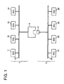
- FIG. 1 is a block diagram showing a schematic construction of a communicaton system according to the embodiment of the present invention.
- a communication network 1 is a standard communication network system, which is less likely to be changed during a development or at the time of a model change, and connects a relay electronic control unit (ECU) 3 and electronic control units ECUs 11 to 14 to each other via a communication bus 10 as shown in FIG. 1 .
- ECU relay electronic control unit
- the ECUs 11 to 14 are, for example, a brake ECU for controlling the orientation and/or braking of a vehicle, a steering ECU for controlling an assist force at the time of steering, a transmission ECU for changing a transmission gear ratio according to speed and engine speed, and/or a suspension ECU for controlling damping forces of shock absorbers, bushes and the like and the spring constants and the like of springs.
- the relay ECU 3 is, for example, a body control ECU provided with a door lock function for controlling the unlocking and locking of one or more doors and/or an illumination control function for controlling the dimming of an interior lamp.
- the relay ECU 3 has a plug-in structure so that a relay unit (relay device) 4 provided with a gateway function for communication protocol conversion can be mounted according to needs.
- the relay ECU 3 and the ECUs 11 to 14 supply power and transmit and receive signals via a wiring harness (not shown) as a preferred bundle of wires assembled with connectors such as terminals and housings, joints, junk blocks, protection devices such as fuses, and one or more covering parts such as tapes and corrugated tubes, wherein the communication bus 10 is also assembled into the wiring harness.
- a wiring harness (not shown) as a preferred bundle of wires assembled with connectors such as terminals and housings, joints, junk blocks, protection devices such as fuses, and one or more covering parts such as tapes and corrugated tubes, wherein the communication bus 10 is also assembled into the wiring harness.
- a communication network 2 is a communication network system suitable for an increase or decrease in the number of ECUs and a revision in communication specifications and connects a relay unit 4 and ECUs 21 to 24 to each other via a communication bus 20.
- the ECUs 21 to 24 are, for example, a security ECU for theft prevention, an air conditioning control ECU for rear seats, and/or an entertainment function ECU and the like, which are suitably ECUs to be added or deleted according to needs.
- relay ECU 3 and the relay unit 4 as characteristic parts of the present invention are described. First of all, the relay ECU 3 is described with reference to FIG. 2 .
- FIG. 2 is a block diagram showing schematic constructions of the relay ECU 3 and the relay unit 4 according to this embodiment.
- the relay ECU 3 according to this embodiment includes one or more circuit connecting portions 31, 33, at least one harness protecting portion 32, at least one controller 34, at least one power supply circuit portion 35, at least one communication circuit portion 36, one or more connectors 37a, 37b and 37c, and/or at least one power supply terminal 38a and/or a communication terminal 38b.
- a wiring harness 51 is connected with the connector 37a
- a wiring harness 52 is connected with the connector 37b
- a wiring harness 53 is connected with the connector 37c.
- the circuit connecting portion 31 is connected between the connectors 37a and 37b for branch connection between wirings included in the wiring harness 51 and those included in the wiring harness 52.
- the harness protecting portion 32 including at least one fuse or protecting circuit for protecting the wiring harnesses 51, 52 is also connected between the connectors 37a and 37b.
- the circuit connecting portion 33 is connected between the connectors 37a and 37c to connect and disconnect wirings included in the wiring harness 51 and those included in the wiring harness 53.
- the controller 34 includes, for example, a microcomputer, receives the supply of operating power from the power supply circuit portion 35, is connected with the communication circuit portion 36 for communication with other ECU(s) and controls the circuit connecting portion 33.
- the controller 34 preferably also simultaneously controls various circuits (not shown) installed in or connected with the relay ECU 3 to realize controls allotted to the relay ECU 3.
- the relay ECU 3 is a body control ECU connected with the communication network 1, various circuits necessary to realize the door lock function for controlling the unlocking and locking of doors, the illumination control function for controlling the dimming of the interior lamp and the like are installed in or connected with the relay ECU 3.
- the power supply circuit portion 35 is connected between the connector 37c and the power supply terminal 38a, converts a power supply voltage supplied from a power supply line 15 included in the wiring harness 53 into a voltage suitable for the operation of an electronic circuit element such as the microcomputer and supplies the resulting voltage to the power supply terminal 38a.
- the power supply voltage supplied from the power supply circuit portion 35 preferably is also supplied to the respective parts of the relay ECU 3 such as the controller 34 to be used for the operations of the respective parts.
- the communication circuit portion 36 is connected between the connector 37c and the communication terminal 38b for transmitting and receiving signals between the communication bus 10 included in the wiring harness 53 and the communication terminal 38b, and causes signals inputted to the relay ECU 3 via the communication bus 10 to be outputted from the communication terminal 38b while causing signals inputted from the communication terminal 38b to be outputted to the communication bus 10.
- the power supply terminal 38a and the communication terminal 38b are or comprise one or more male terminals and arranged on (preferably the bottom surface of) a recessed portion 39 of the relay ECU 3.
- the recessed portion 39 is capable of plug-in connection with a projected portion 44 of the relay unit 4, and a power supply terminal (female terminal) 42a and a communication terminal (female terminal) 42b of the relay unit 4 arranged on the upper surface of the projected portion 44 are respectively connected with the power supply terminal 38a and the communication terminal 38b of the relay ECU 3 by the plug-in connection of the recessed portion 39 and the projected portion 44.
- the relay ECU 3 can be plug-in connected with the relay unit 4 by being provided with the recessed portion 39 capable of plug-in connection with the projected portion 44 of the relay unit 4.
- the respective terminals of the relay ECU 3 and the relay unit 4 are sufficient to be connectable with each other and it does not matter which ones are male terminals and which ones are female terminals.
- the relay unit 4 includes at least one relay circuit portion 41, the power supply terminal 42a and the communication terminal 42b, which are or comprise one or more female terminals, and a communication terminal 43b, which is or comprises at least one male terminal.
- the relay circuit portion 41 is or is to be connected with the power supply terminal 42a and the communication terminals 42b, 43b.
- the relay circuit portion 41 is or comprises a circuit for realizing a gateway function of the relay unit 4, converts the protocol of a signal inputted from the communication terminal 42b and outputs the resulting signal from the communication terminal 43b, and/or preferably converts the protocol of a signal inputted from the communication terminal 43b and outputs the resulting signal from the communication terminal 42b.
- a power supply voltage necessary for the operation of the relay circuit portion 41 is, for example, supplied via the power supply terminal 42a.
- the power supply terminal 42a is or is to be connected with the power supply terminal 38a of the relay ECU 3 by the plug-in connection of the projected portion 44 and the recessed portion 39 of the relay ECU 3, and the power supply voltage supplied from the power supply circuit portion 35 of the relay ECU 3 preferably is supplied to the relay circuit portion 41 via the power supply terminals 38a and 42a.
- the relay circuit portion 41 may be operated by a power supply voltage supplied from the power supply terminal 42a and may supply a part of the supplied power supply voltage to the outside from the relay unit 4 via the power supply terminal 43a.
- a power supply line 26 of the communication network 2 is connected with the power supply terminal 43a.
- the relay ECU 3 and the relay unit 4 preferably can supply the power supply voltage supplied from the power supply line 15 of the communication network 1 to the power supply line 26 of the communication network 2.
- FIGS. 5(a) and 5(b) are diagrams showing a case where three communication networks are connected. As shown in FIGS. 5(a) and 5(b) , a relay ECU 3a and a relay unit 4a are plug-in connected and the relay ECU 3a and a relay unit 4b are plug-in connected between three communication networks 6, 7 and 8.
- FIGS. 6(a) and 6(b) are diagrams showing a case where a new ECU is added and connected to one communication network.
- a relay ECU 3b and a relay unit 4c are plug-in connected in a communication network 9.
- an electronic control unit has a gateway function for connecting a plurality of communication networks formed in a vehicle with each other and performs functions allotted beforehand by transmitting and/or receiving signals via the communication networks.
- the electronic control unit includes at least one plug-in connecting portion 39 to be plug-in connected with at least one relay unit 4 for converting protocols applied to the respective communication networks, thereby connecting the relay unit 4 with a communication bus 10, in the case of performing the gateway function, and at least one communication circuit portion 36 for transmitting and/or receiving signals between the communication bus 10 and the relay unit 4 when the relay unit 4 is plug-in connected with the plug-in connecting portion 39.
Description
- The present invention relates to an electronic control unit and a communication unit capable of connecting a plurality of communication networks formed in a vehicle with each other, and a communication system connected with the electronic control unit and the communication unit and to a respective method.
- There has been conventionally known a communication system in which a plurality of electronic control units (ECUs) for controlling parts of a vehicle are connected via a communication bus to enable mutual data communication. In recent years, with the multiplexing and speeding-up of vehicle communication, a cooperation control among the ECUs has become easier in such a communication system. Specifically, it became possible to connect many ECUs with one communication bus to increase the number of combinations of ECUs for data transfer.
-
EP 1 482 698 A2 discloses a gateway device, which processes only really necessary information for gatewaying and thereby prevents unnecessary increases in communication traffic on a communication bus to which data is sent through the gatewaying. Furthermore, when it is judged that the contents of received data concern a command that does not need gatewaying, the processing for gatewaying is inhibited. When it is judges that contents of the received data show information that should be processed for gatewaying only when there is a change in the contents, the contents are compared with the latest contents of the same kind of information stored in a memory, to determine whether there is a change in the contents, and the processing for gatewaying is inhibited when it is determined that there is no change. -
US 2005/0004735 discloses systems for performing proxy control functions in an environment including one or more work machines. Such systems may leverage one or more gateways to serve as a proxy for one or more distinct modules. A gateway, located in a work machine, may be programmed with proxy logic that performs functions associated with certain modules used in a work machine environment. The gateway may monitor a data link and retrieve broadcasted messages. The gateway may route a retrieved message, using a mapping structure, to the appropriate proxy logic that performs functions associated with the destination module. -
EP 1 718 008 A2 discloses a gateway apparatus that controls a forwarding process of frame data between multiple communication channels. The gateway apparatus includes a search engine that is respectively provided for each of the multiple communication channels to route the frame data between the multiple communication channels, and a first storage portion that is respectively provided for each of the multiple communication channels to temporarily stores the frame data routed. - According to known technology, the communication system as above is separated into a plurality of communication buses and these plurality of communication buses are connected via a relay device such as a gateway to construct a multiplexed communication system (see, for example, Japanese Unexamined Patent Publication No.
2000-78179 2003-17581 2002-271994 - Japanese Unexamined Patent Publication No.
2000-78179 2003-17581 - Japanese Unexamined Patent Publication No.
2003-17581 - However, the following problem was present in the case of utilizing the electrical connection boxes disclosed in the above documents as a relay device of a multiplexed communication system for vehicle.
- Specifically, in the multiplexed communication system for vehicle, a relay device, which was unnecessary at an initial stage of development, may possibly become necessary at a later stage of development or conversely a relay, which was necessary at an initial stage of development, may possibly become unnecessary at a later stage due to an increase or decrease in the number of ECUs, a revision in communication specifications during the development of the communication system.
- If a new relay device becomes necessary at the later stage of development, there is no place for installing the new relay device in many cases. Even if an installation place could be ensured, the communication bus and the wiring harness including the communication bus need to be laid again, with the result that the installation of the new relay device is often difficult.
- On the other hand, if the relay device becomes unnecessary at the later stage of development, wires and an installation place for the relay device may be wasted. Particularly, in the case of incorporating the relay device into an ECU having another function for cost reduction or other reasons instead of realizing the relay device as an independent device, the relay device is wasted without being used, which increases cost on the contrary.
- In view of the above problems, an object of the present invention is to provide an electronic control unit, a communication unit and a communication system and method capable of preventing an increase in development cost resulting from the addition or deletion of a relay device even in the case of an increase or decrease in the number of ECUs, a revision in communication specifications or the like during the development of the communication system.
- This object is solved according to the invention by the features of the independent claims. Preferred embodiments of the invention are subject of the dependent claims.
- According to one aspect of the present invention there is provided an electronic control unit having a gateway function for connecting a plurality of communication networks formed in a vehicle with each other and performing functions allotted beforehand by transmitting and receiving signals via the communication networks, comprising:
- at least one plug-in connecting portion connected with a communication line for carrying signals transmitted from and/or received by the electronic control unit and to be plug-in connected with a relay unit for converting protocols applied to the respective communication networks, thereby connecting the relay unit with the communication line, when the electronic control unit performs the gateway function, and
- at least one communication circuit portion for transmitting and/or receiving signals between the communication line and the relay unit when the relay unit is plug-in connected with the plug-in connecting portion.
- In the above electronic control unit, the relay unit for converting different protocols is connected via the plug-in connecting portion to convert the protocols of signals inputted to and/or outputted from the communication line using the relay unit in the case of performing the gateway function. Thus, even if it becomes necessary to add or delete the relay unit due to an increase in the number of the ECUs, a revision in communication specifications or the like during the development of a communication system, the relay unit can be added to or deleted from the communication system without requiring a design change of the communication system or the like through the plug-in connection of the relay unit or the cancellation of such connection.
- It is preferable to further comprise a power supply circuit portion connected with a power supply line for supplying a power supply voltage to the electronic control unit and adapted to supply a part of the power supply voltage supplied from the power supply line to the relay unit via the plug-in connecting portion when the relay unit is plug-in connected with the plug-in connecting portion.
- In this case, since the power supply voltage necessary for the operation of the relay unit can be supplied from a power supply control unit, it is not necessary to provide a new power supply line for supplying the power supply voltage to the relay unit, thereby reducing development cost.
- Another aspect of the present invention is directed to a communication unit for connecting a plurality of communication networks formed in a vehicle, comprising:
- an electronic control unit having a gateway function for connecting the plurality of communication networks with each other and performing functions allotted beforehand by transmitting and receiving signals via the communication networks,
- at least one relay unit for converting protocols applied to the respective communication networks for the mutual connection of the communication networks,
- at least one plug-in connecting portion connected with a communication line for carrying signals transmitted from and/or received by the electronic control unit and to be plug-in connected with the relay unit, thereby connecting the relay unit with the communication line, when the electronic control unit performs the gateway function, and
- at least one communication circuit portion for transmitting and/or receiving signals between the communication line and the relay unit when the relay unit is plug-in connected with the plug-in connecting portion.
- In the above communication unit, the relay unit for converting different protocols is connected with the electronic control unit via the plug-in connecting portion to convert the protocols of signals inputted to and/or outputted from the communication line using the relay unit in the case of performing the gateway function. Thus, even if it becomes necessary to add or delete the relay unit due to an increase in the number of the ECUs, a revision in communication specifications or the like during the development of a communication system, the relay unit can be added to or deleted from the communication system without requiring a design change of the communication system or the like through the plug-in connection of the relay unit or the cancellation of such connection.
- It is preferable that the relay unit includes first and second input/output portions to be plug-in connected with the plug-in connecting portion, and a relay circuit portion connected between the first and second input/output portions for converting the protocol of a signal inputted from one of the first and second input/output portions and outputting the signal having the protocol converted to the other input/output portion. Further preferably, the second input/output portion is connected either to the communication network different from the one, to which the electronic control unit belongs, or to an electronic control unit different from the electronic control unit or to both.
- In this case, even if it becomes necessary to add a new communication network as the communication specifications are revised, the new communication network can be added and connected without laying a new communication bus by connecting the relay unit with the electronic control unit. Further, even if the ECUs belonging to the communication network run out due to a change in control contents, a new ECU can be added to the communication network by connecting the relay unit with the electronic control unit.
- The electronic control unit preferably further comprises a power supply circuit portion connected with a power supply line for supplying a power supply voltage to the electronic control unit and adapted to supply a part of the power supply voltage supplied from the power supply line to the relay unit via the plug-in connecting portion when the relay unit is plug-in connected with the plug-in connecting portion.
- In this case, since the power supply voltage necessary for the operation of the relay unit can be supplied from a power supply control unit, it is not necessary to provide a new power supply line for supplying the power supply voltage to the relay unit, thereby reducing development cost.
- Still another aspect of the present invention is directed to a communication system, comprising:
- a plurality of communication networks formed in a vehicle,
- an electronic control unit having a gateway function for connecting the communication networks with each other and performing functions allotted beforehand by transmitting and receiving signals via the communication networks,
- at least one relay unit for converting protocols applied to the respective communication networks for the mutual connection of the communication networks,
- at least one plug-in connecting portion connected with a communication line for carrying signals transmitted from and/or received by the electronic control unit and to be plug-in connected with the relay unit, thereby connecting the relay unit with the communication line, when the electronic control unit performs the gateway function, and
- at least one communication circuit portion for transmitting and/or receiving signals between the communication line and the relay unit when the relay unit is plug-in connected with the plug-in connecting portion.
- In the above communication system, the relay unit for converting different protocols is connected with the electronic control unit via the plug-in connecting portion to convert the protocols of signals inputted to and outputted from the communication line using the relay unit in the case of performing the gateway function. Thus, even if it becomes necessary to add or delete the relay unit due to an increase in the number of the ECUs, a revision in communication specifications or the like during the development of the communication system, the relay unit can be added to or deleted from the communication system without requiring a design change of the communication system or the like through the plug-in connection of the relay unit or the cancellation of such connection.
- Still another aspect of the present invention is directed to a communication method, comprising the following steps:
- providing a plurality of communication networks formed in a vehicle,
- connecting the communication networks with each other by means of an electronic control unit having a gateway function and performing functions allotted beforehand by transmitting and/or receiving signals via the communication network),
- converting protocols applied to the respective communication networks for the mutual connection of the communication networks by means of at least one relay unit,
- connecting at least one plug-in connecting portion with a communication line for carrying signals transmitted from and/or received by the electronic control unit and plug-in connecting the plug-in connecting portion with the relay unit, thereby connecting the relay unit with the communication line, when the electronic control unit performs the gateway function, and
- transmitting and/or receiving signals between the communication line and the relay unit by means of at least one communication circuit portion when the relay unit is plug-in connected with the plug-in connecting portion.
- According to the above, there can be provided an electronic control unit, a communication unit and a communication system capable of preventing an increase in development cost resulting from the addition or deletion of a relay device even in the case of an increase in the number of ECUs, a revision in communication specifications or the like during the development of the communication system.
- These and other objects, features and advantages of the present invention will become more apparent upon reading of the following detailed description of preferred embodiments and accompanying drawings. It should be understood that even though embodiments are separately described, single features thereof may be combined to additional embodiments.
-
FIG. 1 is a block diagram showing a schematic construction of a communication system according to one embodiment of the invention, -
FIG. 2 is a block diagram showing schematic constructions of a relay ECU and a relay unit according to the embodiment of the invention, -
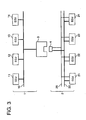
FIG. 3 is a block diagram showing another schematic construction of a communication system according to the embodiment of the invention, -
FIG. 4 is a block diagram showing other schematic constructions of a relay ECU and a relay unit according to the embodiment of the invention, -
FIGS. 5 are diagrams showing a case where three communication networks are connected, whereinFIG. 5(a) shows a state before connection andFIG. 5(b) shows a state after connection, and -
FIGS. 6 are diagrams showing a case where a new ECU is added and connected to one communication system, whereinFIG. 6(a) shows a state before connection andFIG. 6(b) shows a state after connection. - Hereinafter, one preferred embodiment of the present invention is described with reference to the accompanying drawings. In the following description of the drawings, same or similar elements are identified by same or similar reference numerals and are not repeatedly described in some cases.
-
FIG. 1 is a block diagram showing a schematic construction of a communicaton system according to the embodiment of the present invention. In the communication system according to this embodiment, a communication network 1 is a standard communication network system, which is less likely to be changed during a development or at the time of a model change, and connects a relay electronic control unit (ECU) 3 and electroniccontrol units ECUs 11 to 14 to each other via acommunication bus 10 as shown inFIG. 1 . - The
ECUs 11 to 14 are, for example, a brake ECU for controlling the orientation and/or braking of a vehicle, a steering ECU for controlling an assist force at the time of steering, a transmission ECU for changing a transmission gear ratio according to speed and engine speed, and/or a suspension ECU for controlling damping forces of shock absorbers, bushes and the like and the spring constants and the like of springs. - The
relay ECU 3 is, for example, a body control ECU provided with a door lock function for controlling the unlocking and locking of one or more doors and/or an illumination control function for controlling the dimming of an interior lamp. - The
relay ECU 3 has a plug-in structure so that a relay unit (relay device) 4 provided with a gateway function for communication protocol conversion can be mounted according to needs. - The
relay ECU 3 and theECUs 11 to 14 supply power and transmit and receive signals via a wiring harness (not shown) as a preferred bundle of wires assembled with connectors such as terminals and housings, joints, junk blocks, protection devices such as fuses, and one or more covering parts such as tapes and corrugated tubes, wherein thecommunication bus 10 is also assembled into the wiring harness. - A
communication network 2 is a communication network system suitable for an increase or decrease in the number of ECUs and a revision in communication specifications and connects arelay unit 4 andECUs 21 to 24 to each other via acommunication bus 20. TheECUs 21 to 24 are, for example, a security ECU for theft prevention, an air conditioning control ECU for rear seats, and/or an entertainment function ECU and the like, which are suitably ECUs to be added or deleted according to needs. - Next, the
relay ECU 3 and therelay unit 4 as characteristic parts of the present invention are described. First of all, therelay ECU 3 is described with reference toFIG. 2 . -
FIG. 2 is a block diagram showing schematic constructions of therelay ECU 3 and therelay unit 4 according to this embodiment. As shown inFIG. 2 , therelay ECU 3 according to this embodiment includes one or morecircuit connecting portions harness protecting portion 32, at least onecontroller 34, at least one powersupply circuit portion 35, at least onecommunication circuit portion 36, one ormore connectors power supply terminal 38a and/or acommunication terminal 38b. - In the
relay ECU 3 according to this embodiment, awiring harness 51 is connected with theconnector 37a, awiring harness 52 is connected with theconnector 37b and awiring harness 53 is connected with theconnector 37c. Thecircuit connecting portion 31 is connected between theconnectors wiring harness 51 and those included in thewiring harness 52. Theharness protecting portion 32 including at least one fuse or protecting circuit for protecting the wiring harnesses 51, 52 is also connected between theconnectors circuit connecting portion 33 is connected between theconnectors wiring harness 51 and those included in thewiring harness 53. - The
controller 34 includes, for example, a microcomputer, receives the supply of operating power from the powersupply circuit portion 35, is connected with thecommunication circuit portion 36 for communication with other ECU(s) and controls thecircuit connecting portion 33. Thecontroller 34 preferably also simultaneously controls various circuits (not shown) installed in or connected with therelay ECU 3 to realize controls allotted to therelay ECU 3. For example, if therelay ECU 3 is a body control ECU connected with the communication network 1, various circuits necessary to realize the door lock function for controlling the unlocking and locking of doors, the illumination control function for controlling the dimming of the interior lamp and the like are installed in or connected with therelay ECU 3. - The power
supply circuit portion 35 is connected between theconnector 37c and thepower supply terminal 38a, converts a power supply voltage supplied from apower supply line 15 included in thewiring harness 53 into a voltage suitable for the operation of an electronic circuit element such as the microcomputer and supplies the resulting voltage to thepower supply terminal 38a. The power supply voltage supplied from the powersupply circuit portion 35 preferably is also supplied to the respective parts of therelay ECU 3 such as thecontroller 34 to be used for the operations of the respective parts. - The
communication circuit portion 36 is connected between theconnector 37c and thecommunication terminal 38b for transmitting and receiving signals between thecommunication bus 10 included in thewiring harness 53 and thecommunication terminal 38b, and causes signals inputted to therelay ECU 3 via thecommunication bus 10 to be outputted from thecommunication terminal 38b while causing signals inputted from thecommunication terminal 38b to be outputted to thecommunication bus 10. - As shown in
FIG. 2 , thepower supply terminal 38a and thecommunication terminal 38b are or comprise one or more male terminals and arranged on (preferably the bottom surface of) a recessedportion 39 of therelay ECU 3. The recessedportion 39 is capable of plug-in connection with a projectedportion 44 of therelay unit 4, and a power supply terminal (female terminal) 42a and a communication terminal (female terminal) 42b of therelay unit 4 arranged on the upper surface of the projectedportion 44 are respectively connected with thepower supply terminal 38a and thecommunication terminal 38b of therelay ECU 3 by the plug-in connection of the recessedportion 39 and the projectedportion 44. In this way, therelay ECU 3 can be plug-in connected with therelay unit 4 by being provided with the recessedportion 39 capable of plug-in connection with the projectedportion 44 of therelay unit 4. The respective terminals of therelay ECU 3 and therelay unit 4 are sufficient to be connectable with each other and it does not matter which ones are male terminals and which ones are female terminals. - Next, the
relay unit 4 is described with reference toFIG. 2 . - As shown in
FIG. 2 , therelay unit 4 according to this embodiment includes at least onerelay circuit portion 41, thepower supply terminal 42a and thecommunication terminal 42b, which are or comprise one or more female terminals, and acommunication terminal 43b, which is or comprises at least one male terminal. - In the
relay unit 4 according to this embodiment, therelay circuit portion 41 is or is to be connected with thepower supply terminal 42a and thecommunication terminals relay circuit portion 41 is or comprises a circuit for realizing a gateway function of therelay unit 4, converts the protocol of a signal inputted from thecommunication terminal 42b and outputs the resulting signal from thecommunication terminal 43b, and/or preferably converts the protocol of a signal inputted from thecommunication terminal 43b and outputs the resulting signal from thecommunication terminal 42b. In this way, various signals can be transmitted and received between theECUs 11 to 14 and therelay ECU 3 of the communication network 1 and therelay unit 4 and theECUs 21 to 24 of thecommunication network 2, and the respective ECUs can realize the allotted functions in cooperation with the functions of the ECUs connected with the different communication network. - A power supply voltage necessary for the operation of the
relay circuit portion 41 is, for example, supplied via thepower supply terminal 42a. Thepower supply terminal 42a is or is to be connected with thepower supply terminal 38a of therelay ECU 3 by the plug-in connection of the projectedportion 44 and the recessedportion 39 of therelay ECU 3, and the power supply voltage supplied from the powersupply circuit portion 35 of therelay ECU 3 preferably is supplied to therelay circuit portion 41 via thepower supply terminals - As shown in
FIGS. 3 and4 , therelay circuit portion 41 may be operated by a power supply voltage supplied from thepower supply terminal 42a and may supply a part of the supplied power supply voltage to the outside from therelay unit 4 via thepower supply terminal 43a. In therelay unit 4 ofFIGS. 3 and4 , apower supply line 26 of thecommunication network 2 is connected with thepower supply terminal 43a. Thus, therelay ECU 3 and therelay unit 4 preferably can supply the power supply voltage supplied from thepower supply line 15 of the communication network 1 to thepower supply line 26 of thecommunication network 2. - Although the relay ECU and the relay unit for relaying between the two
communication networks 1, 2 are described in this embodiment, the embodiment is not limited to this.FIGS. 5(a) and 5(b) are diagrams showing a case where three communication networks are connected. As shown inFIGS. 5(a) and 5(b) , arelay ECU 3a and arelay unit 4a are plug-in connected and therelay ECU 3a and arelay unit 4b are plug-in connected between three communication networks 6, 7 and 8. By doing so, various signals can be transmitted and received between ECUs 1 to 3 of the communication network 6,ECUs 4, 5 of the communication network 7 and ECUs 6, 7 of the communication network 8, and the respective ECUS can realize allotted functions in cooperation with functions of the ECUs connected with the different communication networks. - The relay ECU and the relay unit of this embodiment are also applicable in the case of adding and/or connecting at least one new ECU for executing the same or similar control as the preinstalled ECU to one communication network.
FIGS. 6(a) and 6(b) are diagrams showing a case where a new ECU is added and connected to one communication network. As shown inFIGS. 6(a) and 6(b) , arelay ECU 3b and arelay unit 4c are plug-in connected in a communication network 9. By doing so, even if it becomes necessary to extend a communication bus through the addition or the like of a new ECU at a later stage of the development of a communication system, the new ECU can be added utilizing existing power supply and signal communication. Therefore, cost increase resulting from the extension of the communication bus can be suppressed without requiring a drastic change, for example, in wiring. - Accordingly, to provide an electronic control unit, a communication unit and a communication system capable of preventing an increase in development cost resulting from the addition or deletion of a relay device, an electronic control unit has a gateway function for connecting a plurality of communication networks formed in a vehicle with each other and performs functions allotted beforehand by transmitting and/or receiving signals via the communication networks. The electronic control unit includes at least one plug-in connecting
portion 39 to be plug-in connected with at least onerelay unit 4 for converting protocols applied to the respective communication networks, thereby connecting therelay unit 4 with acommunication bus 10, in the case of performing the gateway function, and at least onecommunication circuit portion 36 for transmitting and/or receiving signals between thecommunication bus 10 and therelay unit 4 when therelay unit 4 is plug-in connected with the plug-in connectingportion 39. - The embodiment of the present invention disclosed this time is merely an example and the present invention is not limited to this. The scope of the present invention is indicated not by the disclosed contents, but by the appended claims, and is intended to embrace meaning equivalent to the appended claims and all changes within the scope of the claims.
-
- 1, 2, 6, 7, 8, 9 ...
- communication network
- 3, 3a, 3b ...
- relay ECU
- 4, 4a, 4b, 4c ...
- relay unit
- 10, 20...
- communication bus
- 11, 12, 13, 14, 21, 22, 23, 24 ...
- ECU
- 15, 26...
- power supply line
- 31, 33...
- circuit connecting portion
- 32 ...
- harness protecting portion
- 34 ...
- controller
- 35 ...
- power supply circuit portion
- 36 ...
- communication circuit portion
- 37a, 37b, 37c ...
- connector
- 38a, 42a, 43a ...
- power supply terminals
- 38b, 42b, 43b ...
- communication terminal
- 39 ...
- recessed portion
- 41 ...
- relay circuit portion
- 44 ...
- projected portion
- 51,52,53 ...
- wiring harness
Claims (6)
- An electronic control unit having a gateway function for connecting a plurality of communication networks (1, 2, 6, 7, 8, 9) formed in a vehicle with each other, and wherein the electronic control unit performs control functions allotted beforehand by transmitting and/or receiving signals via the communication networks (1, 2, 6, 7, 8, 9), characterized by comprising
at least one plug-in connecting portion (39) connected with a communication line (10) for carrying signals transmitted from and/or received by the electronic control unit and to be plug-in connected with a relay unit (4) having a relay circuit portion (41) for converting protocols applied to the respective communication networks (1, 2, 6, 7, 8, 9), thereby connecting the relay unit (4) with the communication line (10), when the electronic control unit performs the gateway function, wherein the relay unit (4) includes first and second communication terminals (42b, 43b), the first communication terminal (42b) to be plug-in connected with the plug-in connecting portion (39), and the relay circuit portion (41) connected between the first and second communication terminals (42b, 43b) for converting the protocol of a signal inputted from one (42b) of the first and second communication terminals (42b, 43b) and outputting the signal having the protocol converted to the other communication terminal (43b) and
at least one communication circuit portion (36) for transmitting and/or receiving signals between the communication line (10) and the relay unit (4) when the relay unit (4) is plug-in connected with the plug-in connecting portion (39). - An electronic control unit according to claim 1. further comprising a power supply circuit portion (35) connected with a power supply line for supplying a power supply voltage to the electronic control unit and the power supply voltage supplied from the power supply circuit portion (35) is supplied to the relay circuit portion (41) via power supply terminals (38a; 42a) when the relay unit (4) is plug-in connected with the plug-in connecting portion (39).
- An electronic control unit according to claim 1 or 2, wherein
the relay unit (4) is connected to the electronic control unit for converting protocols applied to the respective communication networks (1, 2, 6, 7, 8, 9) for the mutual connection of the communication networks (1, 2, 6, 7, 8, 9). - An electronic control unit according to claim 3, wherein the second communication terminal (43b) is connected to the communication network different from the one, to which the electronic control unit belongs, and/or to an electronic control unit different from the electronic control unit.
- A communication system, comprising:a plurality of communication networks (1, 2, 6, 7, 8, 9) formed in a vehicle,an electronic control unit according to claim 1 or 2, andat least one relay unit (4) for converting protocols applied to the respective communication networks (1, 2, 6, 7, 8, 9) for the mutual connection of the communication networks (1, 2, 6, 7, 8, 9).
- A communication method, comprising the following steps:providing a plurality of communication networks (1, 2, 6, 7, 8, 9) formed in a vehicle,connecting the communication networks (1, 2, 6, 7, 8, 9) with each other by means of an electronic control unit having a gateway function, and wherein the electronic control unit performs control functions allotted beforehand by transmitting and/or receiving signals via the communication networks (1, 2, 6, 7, 8, 9), characterized byconverting protocols applied to the respective communication networks (1, 2, 6, 7, 8, 9) for the mutual connection of the communication networks (1, 2, 6, 7, 8, 9) by means of at least one relay unit (4) having a relay circuit portion (41),connecting at least one plug-in connecting portion (39) with a communication line (10) for carrying signals transmitted from and/or received by the electronic control unit and plug-in connecting the plug-in connecting portion (39) with the relay unit (4), thereby connecting the relay unit (4) with the communication line (10), when the electronic control unit performs the gateway function, andtransmitting and/or receiving signals between the communication line (10) and the relay unit (4) by means of at least one communication circuit portion (36) when the relay unit (4) is plug-in connected with the plug-in connecting portion (39) whereinthe relay unit (4) includes first and second communication terminals (42b, 43b), the first communication terminal (42b) to be plug-in connected with the plug-in connecting portion (39), and the relay circuit portion (41) connected between the first and second communication terminals (42b, 43b) for converting the protocol of a signal inputted from one (42b) of the communication terminals (42b, 43b) and outputting the signal having the protocol converted to the other communication terminal (43b).
Applications Claiming Priority (1)
| Application Number | Priority Date | Filing Date | Title |
|---|---|---|---|
| JP2007295151A JP4924373B2 (en) | 2007-11-14 | 2007-11-14 | Communication unit and communication system |
Publications (2)
| Publication Number | Publication Date |
|---|---|
| EP2061206A1 EP2061206A1 (en) | 2009-05-20 |
| EP2061206B1 true EP2061206B1 (en) | 2011-04-06 |
Family
ID=40351861
Family Applications (1)
| Application Number | Title | Priority Date | Filing Date |
|---|---|---|---|
| EP08019645A Expired - Fee Related EP2061206B1 (en) | 2007-11-14 | 2008-11-10 | An electronic control unit, a communication system and method |
Country Status (4)
| Country | Link |
|---|---|
| US (1) | US9100450B2 (en) |
| EP (1) | EP2061206B1 (en) |
| JP (1) | JP4924373B2 (en) |
| DE (1) | DE602008005985D1 (en) |
Cited By (1)
| Publication number | Priority date | Publication date | Assignee | Title |
|---|---|---|---|---|
| RU2735582C1 (en) * | 2017-05-08 | 2020-11-03 | Вебасто Се | Programmable connector |
Families Citing this family (3)
| Publication number | Priority date | Publication date | Assignee | Title |
|---|---|---|---|---|
| JP2011093374A (en) * | 2009-10-28 | 2011-05-12 | Yazaki Corp | Wire harness, and electronic equipment control system |
| US10909785B2 (en) | 2017-03-06 | 2021-02-02 | Trimark Corporation | Base control module for vehicles |
| JP2020050048A (en) * | 2018-09-25 | 2020-04-02 | 株式会社オートネットワーク技術研究所 | Relay device system |
Family Cites Families (26)
| Publication number | Priority date | Publication date | Assignee | Title |
|---|---|---|---|---|
| JPH06276571A (en) * | 1993-01-22 | 1994-09-30 | Furukawa Electric Co Ltd:The | Multiple transmission device |
| JP3043274B2 (en) * | 1996-04-23 | 2000-05-22 | 株式会社ハーネス総合技術研究所 | In-vehicle electronic control unit |
| EP1482698A3 (en) | 1997-10-24 | 2006-03-22 | Fujitsu Ten Limited | Communication gateway device |
| JP2000078179A (en) | 1998-08-27 | 2000-03-14 | Fujikura Ltd | Electric connection box for automobile |
| US6147938A (en) * | 1998-09-11 | 2000-11-14 | Mazda Motor Corporation | Vehicle electronic system |
| US6711138B1 (en) * | 1999-09-30 | 2004-03-23 | Conexant Systems, Inc. | Digital subscriber line/home phoneline network router |
| JP2002271944A (en) | 2001-03-09 | 2002-09-20 | Auto Network Gijutsu Kenkyusho:Kk | Electric connection box |
| GB0120686D0 (en) * | 2001-08-24 | 2001-10-17 | Intuwave Ltd | Data packet router for a wireless communication device |
| JP3669327B2 (en) | 2001-12-13 | 2005-07-06 | 住友電気工業株式会社 | Electrical junction box for vehicle and in-vehicle gateway |
| ITTO20020028A1 (en) | 2002-01-10 | 2003-07-10 | Magneti Marelli Sistemi Elettr | INTEGRATED ELECTRONIC CONTROL UNIT FOR VEHICLES. |
| US8086365B2 (en) * | 2002-07-29 | 2011-12-27 | Robert Bosch Gmbh | Prioritization method of information transmitters, particularly for executing the coordinated drive train control of a motor vehicle |
| US7983820B2 (en) * | 2003-07-02 | 2011-07-19 | Caterpillar Inc. | Systems and methods for providing proxy control functions in a work machine |
| JP3982762B2 (en) * | 2004-10-26 | 2007-09-26 | 三菱電機株式会社 | In-vehicle electronic control unit |
| DE102004060301A1 (en) * | 2004-12-15 | 2006-06-22 | Robert Bosch Gmbh | Method for initializing an electronic system comprising a plurality of plug-ins |
| JP2006182138A (en) * | 2004-12-27 | 2006-07-13 | Toyota Motor Corp | Data recording system |
| JP2006333438A (en) * | 2005-04-28 | 2006-12-07 | Fujitsu Ten Ltd | Gateway apparatus and routing method |
| JP2006352553A (en) * | 2005-06-16 | 2006-12-28 | Nissan Motor Co Ltd | On-vehicle communication system and on-vehicle gateway device |
| US20070228826A1 (en) * | 2006-03-31 | 2007-10-04 | Jordan Patrick D | Modular, extensible electrical and communication systems, methods, and devices |
| JP5028852B2 (en) | 2006-04-25 | 2012-09-19 | 株式会社デンソー | Vehicle communication system |
| JP5095130B2 (en) * | 2006-05-26 | 2012-12-12 | 株式会社オートネットワーク技術研究所 | Relay connection unit |
| US8014915B2 (en) * | 2006-06-21 | 2011-09-06 | Sungkyunkwan University Foundation For Corporate Collaboration | Vehicle management system and method using ECU |
| US20080163312A1 (en) * | 2006-12-28 | 2008-07-03 | Meca Communications, Inc. | System and method for providing content relating to a communication |
| JP4880035B2 (en) * | 2007-04-05 | 2012-02-22 | 株式会社オートネットワーク技術研究所 | In-vehicle relay connection unit |
| JP2010187423A (en) * | 2007-04-25 | 2010-08-26 | Toyota Motor Corp | Controller for vehicle |
| JP5107608B2 (en) * | 2007-05-16 | 2012-12-26 | 矢崎総業株式会社 | Relay connector unit and electronic device communication system |
| JP5527270B2 (en) * | 2011-04-12 | 2014-06-18 | 株式会社デンソー | In-vehicle electronic control unit |
-
2007
- 2007-11-14 JP JP2007295151A patent/JP4924373B2/en not_active Expired - Fee Related
-
2008
- 2008-11-05 US US12/265,055 patent/US9100450B2/en not_active Expired - Fee Related
- 2008-11-10 EP EP08019645A patent/EP2061206B1/en not_active Expired - Fee Related
- 2008-11-10 DE DE602008005985T patent/DE602008005985D1/en active Active
Cited By (1)
| Publication number | Priority date | Publication date | Assignee | Title |
|---|---|---|---|---|
| RU2735582C1 (en) * | 2017-05-08 | 2020-11-03 | Вебасто Се | Programmable connector |
Also Published As
| Publication number | Publication date |
|---|---|
| US20090125162A1 (en) | 2009-05-14 |
| EP2061206A1 (en) | 2009-05-20 |
| DE602008005985D1 (en) | 2011-05-19 |
| JP2009124364A (en) | 2009-06-04 |
| JP4924373B2 (en) | 2012-04-25 |
| US9100450B2 (en) | 2015-08-04 |
Similar Documents
| Publication | Publication Date | Title |
|---|---|---|
| WO2017222071A1 (en) | Vehicle circuit structure | |
| US8935454B2 (en) | Connectors transmitting/receiving an input/output signal as a communication signal, communication harness with the connectors, and the communication system with the connectors | |
| US8688323B2 (en) | Wire harness and electronic device control system | |
| JP5022740B2 (en) | Relay connector unit, wire harness assembly, and electronic device control system | |
| JPH07507909A (en) | Automotive communication system | |
| JP2006347258A (en) | Car-mounted adapter for communication and wire harness for automobile | |
| WO2017146208A1 (en) | Vehicular wire harness structure | |
| EP2061206B1 (en) | An electronic control unit, a communication system and method | |
| JP3669327B2 (en) | Electrical junction box for vehicle and in-vehicle gateway | |
| EP0507428B1 (en) | Multipath transmission system | |
| WO2007032488A1 (en) | Car-mounted load drive control system | |
| KR20110047301A (en) | A vehicle integrated control system | |
| CN111147338A (en) | Interface design method from vehicle-mounted wired network to wireless network | |
| WO1994026558A1 (en) | Vehicle communication/control system | |
| JP2012105502A (en) | Wire harness | |
| JP2006192970A (en) | On-vehicle communication connector and on-vehicle communication system | |
| US20050210298A1 (en) | Method for controlling a plurality of units networked to give a network, and network comprising a plurality of networked units | |
| US6909952B2 (en) | Device for controlling/regulating the operational sequences in a motor vehicle | |
| US20070223180A1 (en) | Intrinsically Safe Data Transmission Device | |
| KR101165854B1 (en) | Self-Diagnosis System For MOST System | |
| JP2005335622A (en) | In-vehicle device and communication device | |
| WO2023228769A1 (en) | In-vehicle device | |
| WO2023167004A1 (en) | Onboard connection system and onboard system design method | |
| WO2021256228A1 (en) | Relay device | |
| JP2006347257A (en) | Car-mounted communication system |
Legal Events
| Date | Code | Title | Description |
|---|---|---|---|
| PUAI | Public reference made under article 153(3) epc to a published international application that has entered the european phase |
Free format text: ORIGINAL CODE: 0009012 |
|
| 17P | Request for examination filed |
Effective date: 20081120 |
|
| AK | Designated contracting states |
Kind code of ref document: A1 Designated state(s): AT BE BG CH CY CZ DE DK EE ES FI FR GB GR HR HU IE IS IT LI LT LU LV MC MT NL NO PL PT RO SE SI SK TR |
|
| AX | Request for extension of the european patent |
Extension state: AL BA MK RS |
|
| 17Q | First examination report despatched |
Effective date: 20090717 |
|
| AKX | Designation fees paid |
Designated state(s): DE |
|
| GRAP | Despatch of communication of intention to grant a patent |
Free format text: ORIGINAL CODE: EPIDOSNIGR1 |
|
| RTI1 | Title (correction) |
Free format text: AN ELECTRONIC CONTROL UNIT, A COMMUNICATION SYSTEM AND METHOD |
|
| GRAS | Grant fee paid |
Free format text: ORIGINAL CODE: EPIDOSNIGR3 |
|
| GRAA | (expected) grant |
Free format text: ORIGINAL CODE: 0009210 |
|
| AK | Designated contracting states |
Kind code of ref document: B1 Designated state(s): DE |
|
| REF | Corresponds to: |
Ref document number: 602008005985 Country of ref document: DE Date of ref document: 20110519 Kind code of ref document: P |
|
| REG | Reference to a national code |
Ref country code: DE Ref legal event code: R096 Ref document number: 602008005985 Country of ref document: DE Effective date: 20110519 |
|
| PLBE | No opposition filed within time limit |
Free format text: ORIGINAL CODE: 0009261 |
|
| STAA | Information on the status of an ep patent application or granted ep patent |
Free format text: STATUS: NO OPPOSITION FILED WITHIN TIME LIMIT |
|
| 26N | No opposition filed |
Effective date: 20120110 |
|
| REG | Reference to a national code |
Ref country code: DE Ref legal event code: R097 Ref document number: 602008005985 Country of ref document: DE Effective date: 20120110 |
|
| PGFP | Annual fee paid to national office [announced via postgrant information from national office to epo] |
Ref country code: DE Payment date: 20161101 Year of fee payment: 9 |
|
| REG | Reference to a national code |
Ref country code: DE Ref legal event code: R119 Ref document number: 602008005985 Country of ref document: DE |
|
| PG25 | Lapsed in a contracting state [announced via postgrant information from national office to epo] |
Ref country code: DE Free format text: LAPSE BECAUSE OF NON-PAYMENT OF DUE FEES Effective date: 20180602 |