EP2060854A1 - Cooking oven with improved heating assembly - Google Patents
Cooking oven with improved heating assembly Download PDFInfo
- Publication number
- EP2060854A1 EP2060854A1 EP07120942A EP07120942A EP2060854A1 EP 2060854 A1 EP2060854 A1 EP 2060854A1 EP 07120942 A EP07120942 A EP 07120942A EP 07120942 A EP07120942 A EP 07120942A EP 2060854 A1 EP2060854 A1 EP 2060854A1
- Authority
- EP
- European Patent Office
- Prior art keywords
- heating element
- side portions
- central portion
- cooking oven
- baffle
- Prior art date
- Legal status (The legal status is an assumption and is not a legal conclusion. Google has not performed a legal analysis and makes no representation as to the accuracy of the status listed.)
- Granted
Links
- 238000010438 heat treatment Methods 0.000 title claims abstract description 103
- 238000010411 cooking Methods 0.000 title claims abstract description 57
- 244000241796 Christia obcordata Species 0.000 claims 1
- 238000002485 combustion reaction Methods 0.000 description 3
- 230000009977 dual effect Effects 0.000 description 2
- 125000001475 halogen functional group Chemical class 0.000 description 2
- WYTGDNHDOZPMIW-RCBQFDQVSA-N alstonine Natural products C1=CC2=C3C=CC=CC3=NC2=C2N1C[C@H]1[C@H](C)OC=C(C(=O)OC)[C@H]1C2 WYTGDNHDOZPMIW-RCBQFDQVSA-N 0.000 description 1
- 238000005485 electric heating Methods 0.000 description 1
- 239000000463 material Substances 0.000 description 1
- 239000002245 particle Substances 0.000 description 1
- 230000002093 peripheral effect Effects 0.000 description 1
Images


Classifications
-
- F—MECHANICAL ENGINEERING; LIGHTING; HEATING; WEAPONS; BLASTING
- F24—HEATING; RANGES; VENTILATING
- F24C—DOMESTIC STOVES OR RANGES ; DETAILS OF DOMESTIC STOVES OR RANGES, OF GENERAL APPLICATION
- F24C15/00—Details
- F24C15/32—Arrangements of ducts for hot gases, e.g. in or around baking ovens
- F24C15/322—Arrangements of ducts for hot gases, e.g. in or around baking ovens with forced circulation
- F24C15/325—Arrangements of ducts for hot gases, e.g. in or around baking ovens with forced circulation electrically-heated
Definitions
- heating element 30 When mounted on wall 12 of the cooking chamber, heating element 30 is associated to a fan, not shown, which is located in the area defined by central body of the butterfly, so that curved central portion 32 follows the outline of said fan. Therefore, air sucked from the cooking chamber is directed first toward heating element 30, then to side portions 34, 36, to maximise heat exchange.
- the centre of the fan is also the centre of curved portion 32.
- a traditional tubular heating element provided with circular shape can be combined with the butterfly shaped element 30.
- restrictions 53, 55, of side portions 54, 56 join central portion 52, whose size is larger than that of restrictions 53, 55, with a profile that is asymmetrical with respect to a longitudinal axis Y extending through the centre of baffle 16.
- restriction 53 of side portion 54 has a lower profile 53a substantially circular, and an upper profile 53b substantially linear.
- restriction 55 of side portion 56 has a lower profile 55a substantially linear, and an upper profile 55b substantially circular.
- heating assembly 14 is to generate a forced flow of air from chamber 10 into assembly 14 through holes 18 and then back to chamber 14 through holes 19, 19', whereby air re-introduced into chamber 10 is heated.
Landscapes
- Engineering & Computer Science (AREA)
- Chemical & Material Sciences (AREA)
- Combustion & Propulsion (AREA)
- Mechanical Engineering (AREA)
- General Engineering & Computer Science (AREA)
- Electric Stoves And Ranges (AREA)
Abstract
Description
- The present invention relates to a cooking oven with an improved heating assembly. More particularly, the invention relates to a convection cooking oven with an improved heating assembly comprising a heating element associated to a fan and an air distribution baffle located within the cooking chamber.
- Convection ovens comprising electrical heating elements and a fan to circulate hot air within an oven cavity or cooking chamber are known in the art.
-
US 2006/0027560 Al discloses a cooking oven comprising an oven cavity equipped with upper and lower electric heaters and with a convection fan on the rear plate of the oven cavity to circulate hot air through the oven cavity. The function of the convection fan is to keep the temperature in the oven cavity uniform. No heating element associated directly with the convection fan or mounted in the vicinity thereof is disclosed. -
US 6,872,926 B1 discloses a rapid cook oven with dual flow fan assembly comprising an oven air inlet, a fresh air inlet, a mixing chamber, and a combustion chamber in which an electric heating element is housed. The heating element is a coiled wire that takes the form of a halo disposed about the periphery of a dual flow fan within the combustion chamber. Air discharge ports are provided at the bottom and upper portions of fan assembly. The "halo" shape of the heating element disclosed in this document is such that heat is generated in a restricted zone of the combustion chamber, which makes difficult an efficient heat removal and precise control of the temperature of the cooking chamber over a wide temperature range. - Therefore, the need is felt for a cooking oven that is highly efficient in heating the cooking chamber and that provides for a better control of the temperature of the heating element.
- It is therefore the overall object of the present invention to disclose a cooking oven comprising a heating assembly designed to ensure sufficient heating and efficient heat transfer to the cooking chamber.
- It is a further object of the present invention to disclose a cooking oven having a heating assembly with one or more heating elements designed to provide a desired heating power.
- The aforesaid and other objects of the invention, as it will appear from the following description, are achieved by a cooking oven comprising a convection cooking chamber in which a heating assembly is mounted, said heating assembly comprising a baffle, a fan and at least an electrical heating element, said baffle being provided with air inlets and air outlets in communication with said cooking chamber, characterized in that:
- said electrical heating element includes a curved central portion and elongated curved side portions extending from said central portion;
- said baffle comprises a substantially circular central portion located over said fan and said curved central portion of said electrical heating element, and side portions located over said elongated side portion of said heating element;
- said central portion of said baffle is provided with air inlets and said side portions of said baffle are provided with air outlets;
- According to another aspect of the invention, said heating assembly has a butterfly-like shape, with a circular central portion and wing-like side portions extending from said central portion with respect to a central longitudinal axis.
- According to a further aspect of the invention, said side portions of said baffle are formed with restrictions in the vicinity of said central portion of said baffle.
- According to a further aspect of the invention, said restrictions of side portions of said baffle are asymmetrical with respect to a longitudinal axis extending through the centre of said baffle.
- Some embodiments of the invention will now be described by way of example with reference to the attached drawings, wherein:
-
Fig. 1 is a schematic perspective view of a cooking chamber of an oven with a heating assembly according to the invention; -
Fig. 2 is a perspective view of a first embodiment of a heating element to the invention; -
Fig. 3 is a perspective view of a second embodiment of a heating element according to the invention; -
Fig. 3A is a perspective view of an alternative implementation of the heating element described inFig. 3 ; -
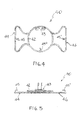
Fig. 4 is a front view of a third embodiment of a heating element according to of the invention; -
Fig. 5 is a top view of the heating element ofFig. 4 ; -
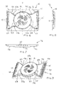
Fig. 6 is a front view of an embodiment of a baffle according to the invention; -
Fig. 7 is a top view of the baffle ofFig. 6 ; -
Fig. 8 is a side view of the baffle ofFig. 6 -
Fig. 9 is a schematic perspective view of the baffle ofFig. 6 . - With reference to
Fig. 1 , aconvection cooking chamber 10 of a cooking oven is schematically represented without front wall or front door. A heating assembly generally designated with 14 is mounted on rearvertical wall 12 ofchamber 10.Heating assembly 14 comprises abaffle 16, behind which a fan (not shown) and at least an electrical heating element are located, as it will be discussed in the following description and shown inFigures 2-5 . Baffle 16 is provided withair inlets 18 andair outlets 19, 19', in communication withcooking chamber 10. The combination of a fan and one or more electrical heating elements generates a forced flow of air fromchamber 10 intoassembly 14 and then back tochamber 14, whereby air re-introduced intochamber 10 is heated. -
Fig. 2 shows a first embodiment of an electrical heating element according to the invention. In such embodiment anelectrical heating element 20 includes a curvedcentral portion 22 having approximately a semi-circular shape, and two elongated andcurved side portions central portion 22. The overall shape ofelement 20 is that of a serpentine with a larger central loop and smaller side loops.End plates heating element 20 are fixed torear wall 12 ofcooking chamber 10, to provide mechanical support and allow electrical connection toelement 22. - When mounted on
wall 12 of the cooking chamber,heating element 20 is associated to a fan, not shown, which is located in the area defined by the central loop, so that curvedcentral portion 22 follows the outline of the corresponding portion of said fan, so that air sucked by the fan from the cooking chamber is directed first toward thecentral portion 22 ofheating element 20, then towardside portions curved portion 22. -
Fig. 3 shows a second embodiment of an electrical heating element according to the invention. In such embodiment anelectrical heating element 30 results from combining twoelements 20 in a mirror-like fashion to form a closed structure consisting of a single elongated heating element whose ends are connected to oneend plate 33. The structure ofheating element 30 includes a curvedcentral portion 32 having approximately a circular shape and two elongated andcurved side portions element 30 is that of a butterfly with a large circular central body and smaller wings.Plate 33 located inportion 34 of the heating element is fixed torear wall 12 ofcooking chamber 10, to provide mechanical support and allow for electrical connection toelement 30. Bracket 35, 35'support side portion 36 ofheating element 30. -
Fig. 3A shows an alternative implementation of the heating element described inFig. 3 . - In such embodiment an
electrical heating element 30 results from combining two elements 20A, 20B in a mirror-like fashion to form a single structure consisting of anelongated heating element 30 whose ends are connected to twoend plates 33A and 33B. The overall shape ofelement 30 is that of a butterfly with a large circular central body and smaller wings.Plates 33A and 33B, located inportions rear wall 12 ofcooking chamber 10, to provide mechanical support and allow for electrical connection toelement 30. - Each of the single heating elements 20A, 20B can be dimensioned to supply either the same or different power of the mirrored element (respectively 20B and 20A) or, driven to supply different power levels according to the heating performances that need to be obtained in the
oven cavity 10. Each of the single heating elements 20A, 20B can be activated separately o jointly with the mirrored element, respectively 20B or 20A, for a better control of the heating power and consequently of the temperature into the oven cavity. - When mounted on
wall 12 of the cooking chamber,heating element 30 is associated to a fan, not shown, which is located in the area defined by central body of the butterfly, so that curvedcentral portion 32 follows the outline of said fan. Therefore, air sucked from the cooking chamber is directed first towardheating element 30, then toside portions curved portion 32. A traditional tubular heating element provided with circular shape (not shown), can be combined with the butterfly shapedelement 30. -
Fig. 4 and 5 show a third embodiment of an electrical heating element according to the invention. In such embodiment anelectrical heating element 40 results from combining a butterfly heating element with aring 42, to form to a single-wire structure. The butterfly part ofheating element 40 comprises two elongated andcurved side portions portion 42 like the wings of a butterfly. Aplate 43 located in thecentral ring portion 42 of the heating element is fixed torear wall 12 ofcooking chamber 10, to provide mechanical support and allow for electrical connection toelement 40.Bracket side portions central portion 42 ofheating element 40, respectively. - When mounted on
wall 12 of the cooking chamber,heating element 40 is associated to a fan, not shown, which is located in the area defined by central ring-portion, so that central ring-portion 42 follows the outline of said fan. Therefore, air sucked from the cooking chamber is directed towardheating element 40, to maximise heat exchange. Preferably, the centre of the fan is also the centre of central ring-portion 42. - Preferably,
heating elements -
Figures 6-9 show an embodiment of a baffle designated generally with 16, which has the also the function to protect the heating element and the fan described above from particles of food, oil and the like present in the cooking chamber.Baffle 16 is fixed torear wall 12 of acooking chamber 10 by fastening means such as screws (not shown) housed inholes 51 of aback plate portion 50.Baffle 16 is shaped with a large portion raised fromback plate portion 50, whose height is shown in particular inFig. 7 and 8 , and that allows to house the fan and the heating element described above. The raised portion has approximately a butterfly shape, and comprises a substantially circularcentral portion 52 andside portions restrictions central portion 52. The overall shape of the raised portion ofbaffle 16 is that of a butterfly, with wings that widen fromrestrictions external ends Central portion 52 is designed to be operatively located over the fan and the central portion of the heating element described above in connection toFigures 2-5 .Side portions baffle 16 are designed to be located over thecorresponding side portions heating element 20; or thecorresponding side portions heating element 30; or thecorresponding side portions heating element 40.Central portion 52 ofbaffle 16 is provided withair inlets 18, andside portions baffle 16 are provided withair outlets 19, 19', located on said widened external ends 57, 59 ofside portions air outlets 60 are provided also in the peripheral edge ofcentral portion 52. - According to a preferred aspect of the invention,
restrictions side portions central portion 52, whose size is larger than that ofrestrictions baffle 16. Referring more particularly toFigure 6 and 9 ,restriction 53 ofside portion 54 has alower profile 53a substantially circular, and anupper profile 53b substantially linear. On the contrary,restriction 55 ofside portion 56 has alower profile 55a substantially linear, and an upper profile 55b substantially circular. - The function of
heating assembly 14, as mentioned above, is to generate a forced flow of air fromchamber 10 intoassembly 14 throughholes 18 and then back tochamber 14 throughholes 19, 19', whereby air re-introduced intochamber 10 is heated. - The butterfly shape of
baffle 16encircling heating element separate elements 20, is such that air is effectively circulated withinassembly 14 fromholes 18 toholes 19, 19'. This feature allows to use heating elements of considerable length, which extends with elongated side portions from a central portion, thanks to their curved or serpentine shape. Also, the relative position of fan and heating elements and the superimposed position ofbaffle 16 is such that incoming air flows over the full extension of the heating element, which favours heat exchange. - In particular,
restrictions baffle 16 and therear wall 12 of the cooking chamber in which air flow is redirected to be distributed evenly, thereby avoiding unevenness in air velocity and allowing a more uniformly distributed heat exchange. - Further, the asymmetrical profile of
restrictions side portions restrictions - Also, the possibility to use heating elements of different length and power helps to controlling the amount and speed of heating of the cooking chamber. For instance, a single heating element like
element 20, 20A, 20B can typically supply a power up to 700 W. Elements like 30 or 40 can typically supply a power up to 2800 W. - The convection cooking oven according to the invention is thus capable to provide efficient and effective cooking of food items, combined with high versatility with respect to choice of desired power of the heating element.
- It is clear from the description above that other embodiments of the cooking oven according to the invention are possible within the same inventive concept.
Claims (16)
- Cooking oven comprising a convection cooking chamber (10) in which a heating assembly (14) is mounted, said heating assembly comprising a baffle (16), a fan and at least an electrical heating element (20; 20A; 20B; 30; 40), said baffle (16) being provided with air inlets (18) and air outlets (19, 19') in communication with said cooking chamber (10), characterized in that:- said electrical heating element (20; 20A; 20B; 30; 40) includes a curved central portion (22; 32; 42) and elongated side portions (24, 26; 34,36; 44,46) extending from said central portion;- said baffle (16) comprises a central portion (52) located over said fan and said central portion (22; 32; 42) of said heating element (20; 20A; 30; 40), and side portions (54,56) located over said elongated side portions (24,26; 34,36; 44,46) of said electrical heating element (20; 20A; 30; 40);- said air inlets (18) are provided in said central portion (52) of said baffle (16) and said air outlets (19,19') are provided in said side portions (54,56) of said baffle (16);whereby a forced air flow is generated from said air inlets (18) to said air outlets (19,19') to operatively remove heat from said central (22; 32; 42) and side (24,26; 34,36; 44,46) portions of said heating element (20; 30; 40).
- Cooking oven according to claim 1, characterized in that side portions (54,56) of said baffle (16) are formed with restrictions (53,55) in the vicinity of said central portion (52).
- Cooking oven according to claim 2, characterized in that said baffle (16) of said heating assembly (14) has a butterfly-like shape, with a substantially circular central portion (52) and wing-like side portions (54,56) extending from said restrictions (53,55) to widened external ends (57,59).
- Cooking oven according to claim 3, characterized in that said air outlets (19,19') are located on said widened external ends (57,59) of said baffle (16).
- Cooking oven according to claim 1, characterized in that said curved central portion (22) of said electrical heating element (20, 20A, 20B) is of a substantially semi-circular shape.
- Cooking oven according to claim 5, characterized in that said curved central portion of a substantially semi-circular shape (22) of said electrical heating element (20, 20A, 20B) is mounted coaxially to said fan within said heating assembly (14).
- Cooking oven according to claim 1, characterized in that said curved side portions (24,26) extending laterally from said central portion (22) of said heating element (20, 20A, 20B) are provided with terminal plates (23, 25, 33A, 33B), each of which is located at one side of said central portion (22).
- Cooking oven according to claim 1, characterized in that said central portion (32) of said electrical heating element (30) is substantially of a circular shape.
- Cooking oven according to claim 8, characterized in that the overall shape of said heating element (30) is substantially that of a butterfly, said curved side portions (34, 36) having narrow bends extending laterally from central portion (32) like butterfly wings.
- Cooking oven according to claim 9, characterized in that the ends of said curved side portions (34,36) are provided with one terminal plate (33) and are closed to each other at one side of heating element (30).
- Cooking oven according to claim 1, characterized in that said central portion of said heating element (40) comprises a ring (42) and said curved side portions (44, 46) extending laterally from said ring (42).
- Cooking oven according to claim 11, characterized in that the ends of said heating element (40) are provided with one terminal plate (43) and are closed to each other in correspondence of said central ring (42) of said heating element (40).
- Cooking oven according to claim 2, characterized in that said restrictions (53,55) of said side portions (54,56) are asymmetrical with respect to a longitudinal axis (Y) extending through the centre of said baffle (16).
- Cooking oven according to claim 13, characterized in that the lower profile (53a) of restriction (53) of one (54) of said side portions (54,56) is substantially circular, and the lower profile (55a) of the opposed restriction (55) of said side portions (54,56) is substantially linear.
- Cooking oven according to claim 13, characterized in that the upper profile (53b) of restriction (53) of one (54) of said side portions (54,56) is substantially linear, and the upper profile (55b) of the opposed restriction (55) of said side portions (54,56) is substantially circular.
- Cooking oven according to claim 13-15, characterized in that the lower profile (53a) of restriction (53) of one of said side portions (54) is substantially circular, the lower profile (55a) of the opposed restriction (55) of said side portions is substantially linear, the upper profile (53b) of restriction (53) being substantially linear and the upper profile (55b) of opposed restriction (55) being substantially circular, whereby air flow is delivered in the direction (A,A').
Priority Applications (2)
| Application Number | Priority Date | Filing Date | Title |
|---|---|---|---|
| EP20070120942 EP2060854B1 (en) | 2007-11-19 | 2007-11-19 | Cooking oven with improved heating assembly |
| ES07120942T ES2379493T3 (en) | 2007-11-19 | 2007-11-19 | Kitchen oven with improved heating set |
Applications Claiming Priority (1)
| Application Number | Priority Date | Filing Date | Title |
|---|---|---|---|
| EP20070120942 EP2060854B1 (en) | 2007-11-19 | 2007-11-19 | Cooking oven with improved heating assembly |
Publications (2)
| Publication Number | Publication Date |
|---|---|
| EP2060854A1 true EP2060854A1 (en) | 2009-05-20 |
| EP2060854B1 EP2060854B1 (en) | 2012-02-01 |
Family
ID=40459590
Family Applications (1)
| Application Number | Title | Priority Date | Filing Date |
|---|---|---|---|
| EP20070120942 Ceased EP2060854B1 (en) | 2007-11-19 | 2007-11-19 | Cooking oven with improved heating assembly |
Country Status (2)
| Country | Link |
|---|---|
| EP (1) | EP2060854B1 (en) |
| ES (1) | ES2379493T3 (en) |
Cited By (4)
| Publication number | Priority date | Publication date | Assignee | Title |
|---|---|---|---|---|
| WO2016124789A3 (en) * | 2015-02-06 | 2016-10-27 | Michael James Mcintyre | Cooking apparatus and air delivery and circulation device therefore |
| US11454403B2 (en) * | 2018-09-04 | 2022-09-27 | Whirlpool Corporation | Double oven gas with fan |
| EP4224072A1 (en) * | 2022-02-02 | 2023-08-09 | Whirlpool Corporation | System and method for improved convection airflow in a cooking appliance |
| USD1033127S1 (en) | 2022-02-02 | 2024-07-02 | Whirlpool Corporation | Circulation cover for a convection oven |
Families Citing this family (1)
| Publication number | Priority date | Publication date | Assignee | Title |
|---|---|---|---|---|
| US11852349B2 (en) | 2021-03-11 | 2023-12-26 | Electrolux Home Products, Inc. | Convection heating element |
Citations (12)
| Publication number | Priority date | Publication date | Assignee | Title |
|---|---|---|---|---|
| US3828760A (en) * | 1973-05-23 | 1974-08-13 | Lca Corp | Oven |
| GB1553675A (en) * | 1976-08-31 | 1979-09-26 | Reed International Ltd | Ovens and their method of operation |
| JPS58200935A (en) | 1982-05-19 | 1983-11-22 | Matsushita Electric Ind Co Ltd | heating device |
| JPS5921925A (en) * | 1982-07-26 | 1984-02-04 | Matsushita Electric Ind Co Ltd | heating device |
| US4484063A (en) * | 1980-02-25 | 1984-11-20 | Rival Manufacturing Company | Convection oven |
| US4722683A (en) * | 1986-03-14 | 1988-02-02 | Vulcan-Hart Corporation | Rethermalization oven |
| US5235962A (en) * | 1992-09-08 | 1993-08-17 | Maytag Corporation | Forced circulation oven door |
| US5485780A (en) * | 1993-02-26 | 1996-01-23 | Food Automation Service Techniques, Inc. | Rotisserie oven |
| DE19831087A1 (en) | 1998-07-10 | 2000-01-13 | Bsh Bosch Siemens Hausgeraete | Oven with blower assisted circulation promoting more uniform heating and browning even at lower air flow rates |
| US6872926B1 (en) | 2004-02-25 | 2005-03-29 | Maytag Corporation | Rapid cook oven with dual flow fan assembly |
| US20060027560A1 (en) | 2004-08-09 | 2006-02-09 | Lg Electronics Inc. | Convection part for electric oven range |
| US20060272632A1 (en) | 2005-06-01 | 2006-12-07 | Maytag Corp. | Airflow system for a convection oven |
-
2007
- 2007-11-19 ES ES07120942T patent/ES2379493T3/en active Active
- 2007-11-19 EP EP20070120942 patent/EP2060854B1/en not_active Ceased
Patent Citations (12)
| Publication number | Priority date | Publication date | Assignee | Title |
|---|---|---|---|---|
| US3828760A (en) * | 1973-05-23 | 1974-08-13 | Lca Corp | Oven |
| GB1553675A (en) * | 1976-08-31 | 1979-09-26 | Reed International Ltd | Ovens and their method of operation |
| US4484063A (en) * | 1980-02-25 | 1984-11-20 | Rival Manufacturing Company | Convection oven |
| JPS58200935A (en) | 1982-05-19 | 1983-11-22 | Matsushita Electric Ind Co Ltd | heating device |
| JPS5921925A (en) * | 1982-07-26 | 1984-02-04 | Matsushita Electric Ind Co Ltd | heating device |
| US4722683A (en) * | 1986-03-14 | 1988-02-02 | Vulcan-Hart Corporation | Rethermalization oven |
| US5235962A (en) * | 1992-09-08 | 1993-08-17 | Maytag Corporation | Forced circulation oven door |
| US5485780A (en) * | 1993-02-26 | 1996-01-23 | Food Automation Service Techniques, Inc. | Rotisserie oven |
| DE19831087A1 (en) | 1998-07-10 | 2000-01-13 | Bsh Bosch Siemens Hausgeraete | Oven with blower assisted circulation promoting more uniform heating and browning even at lower air flow rates |
| US6872926B1 (en) | 2004-02-25 | 2005-03-29 | Maytag Corporation | Rapid cook oven with dual flow fan assembly |
| US20060027560A1 (en) | 2004-08-09 | 2006-02-09 | Lg Electronics Inc. | Convection part for electric oven range |
| US20060272632A1 (en) | 2005-06-01 | 2006-12-07 | Maytag Corp. | Airflow system for a convection oven |
Cited By (7)
| Publication number | Priority date | Publication date | Assignee | Title |
|---|---|---|---|---|
| WO2016124789A3 (en) * | 2015-02-06 | 2016-10-27 | Michael James Mcintyre | Cooking apparatus and air delivery and circulation device therefore |
| CN107249334A (en) * | 2015-02-06 | 2017-10-13 | M·J·麦金太尔 | Cooking equipment and its air delivery and circulation |
| US10415836B2 (en) | 2015-02-06 | 2019-09-17 | Michael James McIntyre | Cooking apparatus and air delivery and circulation device therefore |
| US11454403B2 (en) * | 2018-09-04 | 2022-09-27 | Whirlpool Corporation | Double oven gas with fan |
| EP4224072A1 (en) * | 2022-02-02 | 2023-08-09 | Whirlpool Corporation | System and method for improved convection airflow in a cooking appliance |
| USD1033127S1 (en) | 2022-02-02 | 2024-07-02 | Whirlpool Corporation | Circulation cover for a convection oven |
| US12590707B2 (en) | 2022-02-02 | 2026-03-31 | Whirlpool Corporation | System and method for improved convection airflow in a cooking appliance |
Also Published As
| Publication number | Publication date |
|---|---|
| EP2060854B1 (en) | 2012-02-01 |
| ES2379493T3 (en) | 2012-04-26 |
Similar Documents
| Publication | Publication Date | Title |
|---|---|---|
| KR102908724B1 (en) | air fryer | |
| US7411160B2 (en) | Airflow system for a convection oven | |
| CN102216690B (en) | Oven with dual fan convection performance distributor | |
| US7102105B2 (en) | Electric oven | |
| EP1714084B1 (en) | An owen | |
| EP3620722B1 (en) | Gas convection oven | |
| EP2467646B1 (en) | Oven | |
| US20130284161A1 (en) | Oven appliance with features for selecting convection air flow direction | |
| EP2060854B1 (en) | Cooking oven with improved heating assembly | |
| WO2006025133A1 (en) | Heating cooking apparatus | |
| CN216293794U (en) | Countertop cooking system | |
| US6069344A (en) | Convection feature for use in ovens | |
| KR100672475B1 (en) | Multi Duct Convection Microwave Oven | |
| KR101411760B1 (en) | Electric oven | |
| CN110652226B (en) | Baking appliance | |
| CN101203714A (en) | Oven with uniform hot air flow in the preparation area | |
| KR100727875B1 (en) | Oven | |
| CN109984628B (en) | Oven fan system | |
| CN214760665U (en) | Culinary art cavity structures and electric oven with air is fried function | |
| CN215077686U (en) | Protective cover for fan and cooking device | |
| KR200155505Y1 (en) | Microwave Oven Tray | |
| CN218096121U (en) | Cooking device with side hot air fan and integrated kitchen | |
| CN213421190U (en) | Electromagnetic oven | |
| CN223830904U (en) | Cooking utensil | |
| JP3823033B2 (en) | Cooking equipment |
Legal Events
| Date | Code | Title | Description |
|---|---|---|---|
| PUAI | Public reference made under article 153(3) epc to a published international application that has entered the european phase |
Free format text: ORIGINAL CODE: 0009012 |
|
| AK | Designated contracting states |
Kind code of ref document: A1 Designated state(s): AT BE BG CH CY CZ DE DK EE ES FI FR GB GR HU IE IS IT LI LT LU LV MC MT NL PL PT RO SE SI SK TR |
|
| AX | Request for extension of the european patent |
Extension state: AL BA HR MK RS |
|
| 17P | Request for examination filed |
Effective date: 20091021 |
|
| 17Q | First examination report despatched |
Effective date: 20091120 |
|
| AKX | Designation fees paid |
Designated state(s): DE ES FR GB IT |
|
| GRAP | Despatch of communication of intention to grant a patent |
Free format text: ORIGINAL CODE: EPIDOSNIGR1 |
|
| GRAS | Grant fee paid |
Free format text: ORIGINAL CODE: EPIDOSNIGR3 |
|
| GRAA | (expected) grant |
Free format text: ORIGINAL CODE: 0009210 |
|
| AK | Designated contracting states |
Kind code of ref document: B1 Designated state(s): DE ES FR GB IT |
|
| REG | Reference to a national code |
Ref country code: GB Ref legal event code: FG4D |
|
| REG | Reference to a national code |
Ref country code: DE Ref legal event code: R096 Ref document number: 602007020386 Country of ref document: DE Effective date: 20120329 |
|
| REG | Reference to a national code |
Ref country code: ES Ref legal event code: FG2A Ref document number: 2379493 Country of ref document: ES Kind code of ref document: T3 Effective date: 20120426 |
|
| PLBE | No opposition filed within time limit |
Free format text: ORIGINAL CODE: 0009261 |
|
| STAA | Information on the status of an ep patent application or granted ep patent |
Free format text: STATUS: NO OPPOSITION FILED WITHIN TIME LIMIT |
|
| 26N | No opposition filed |
Effective date: 20121105 |
|
| REG | Reference to a national code |
Ref country code: DE Ref legal event code: R097 Ref document number: 602007020386 Country of ref document: DE Effective date: 20121105 |
|
| REG | Reference to a national code |
Ref country code: FR Ref legal event code: PLFP Year of fee payment: 9 |
|
| REG | Reference to a national code |
Ref country code: FR Ref legal event code: PLFP Year of fee payment: 10 |
|
| PGFP | Annual fee paid to national office [announced via postgrant information from national office to epo] |
Ref country code: ES Payment date: 20161011 Year of fee payment: 10 |
|
| REG | Reference to a national code |
Ref country code: FR Ref legal event code: PLFP Year of fee payment: 11 |
|
| REG | Reference to a national code |
Ref country code: FR Ref legal event code: PLFP Year of fee payment: 12 |
|
| PG25 | Lapsed in a contracting state [announced via postgrant information from national office to epo] |
Ref country code: ES Free format text: LAPSE BECAUSE OF NON-PAYMENT OF DUE FEES Effective date: 20171120 |
|
| PGFP | Annual fee paid to national office [announced via postgrant information from national office to epo] |
Ref country code: GB Payment date: 20210930 Year of fee payment: 15 |
|
| PGFP | Annual fee paid to national office [announced via postgrant information from national office to epo] |
Ref country code: FR Payment date: 20211109 Year of fee payment: 15 Ref country code: DE Payment date: 20210929 Year of fee payment: 15 |
|
| PGFP | Annual fee paid to national office [announced via postgrant information from national office to epo] |
Ref country code: IT Payment date: 20211012 Year of fee payment: 15 |
|
| REG | Reference to a national code |
Ref country code: DE Ref legal event code: R119 Ref document number: 602007020386 Country of ref document: DE |
|
| GBPC | Gb: european patent ceased through non-payment of renewal fee |
Effective date: 20221119 |
|
| PG25 | Lapsed in a contracting state [announced via postgrant information from national office to epo] |
Ref country code: IT Free format text: LAPSE BECAUSE OF NON-PAYMENT OF DUE FEES Effective date: 20221119 Ref country code: GB Free format text: LAPSE BECAUSE OF NON-PAYMENT OF DUE FEES Effective date: 20221119 Ref country code: DE Free format text: LAPSE BECAUSE OF NON-PAYMENT OF DUE FEES Effective date: 20230601 |
|
| PG25 | Lapsed in a contracting state [announced via postgrant information from national office to epo] |
Ref country code: FR Free format text: LAPSE BECAUSE OF NON-PAYMENT OF DUE FEES Effective date: 20221130 |