EP2060812A2 - Rolling bearing - Google Patents
Rolling bearing Download PDFInfo
- Publication number
- EP2060812A2 EP2060812A2 EP08019296A EP08019296A EP2060812A2 EP 2060812 A2 EP2060812 A2 EP 2060812A2 EP 08019296 A EP08019296 A EP 08019296A EP 08019296 A EP08019296 A EP 08019296A EP 2060812 A2 EP2060812 A2 EP 2060812A2
- Authority
- EP
- European Patent Office
- Prior art keywords
- rolling
- cage
- bearing
- hydrophilic
- ball
- Prior art date
- Legal status (The legal status is an assumption and is not a legal conclusion. Google has not performed a legal analysis and makes no representation as to the accuracy of the status listed.)
- Granted
Links
- 238000005096 rolling process Methods 0.000 title claims description 79
- GWEVSGVZZGPLCZ-UHFFFAOYSA-N Titan oxide Chemical compound O=[Ti]=O GWEVSGVZZGPLCZ-UHFFFAOYSA-N 0.000 claims abstract description 19
- OGIDPMRJRNCKJF-UHFFFAOYSA-N titanium oxide Inorganic materials [Ti]=O OGIDPMRJRNCKJF-UHFFFAOYSA-N 0.000 claims abstract description 19
- 239000000463 material Substances 0.000 claims description 45
- 239000007787 solid Substances 0.000 claims description 29
- 239000000314 lubricant Substances 0.000 claims description 28
- XLYOFNOQVPJJNP-UHFFFAOYSA-N water Substances O XLYOFNOQVPJJNP-UHFFFAOYSA-N 0.000 claims description 21
- 238000005461 lubrication Methods 0.000 claims description 9
- 230000000717 retained effect Effects 0.000 claims description 4
- 230000001050 lubricating effect Effects 0.000 description 14
- CURLTUGMZLYLDI-UHFFFAOYSA-N Carbon dioxide Chemical compound O=C=O CURLTUGMZLYLDI-UHFFFAOYSA-N 0.000 description 4
- 239000004734 Polyphenylene sulfide Substances 0.000 description 4
- 230000000694 effects Effects 0.000 description 4
- 239000012530 fluid Substances 0.000 description 4
- 239000004973 liquid crystal related substance Substances 0.000 description 4
- 229920002530 polyetherether ketone Polymers 0.000 description 4
- 229920000069 polyphenylene sulfide Polymers 0.000 description 4
- 229920005989 resin Polymers 0.000 description 4
- 239000011347 resin Substances 0.000 description 4
- 239000000126 substance Substances 0.000 description 4
- 150000001875 compounds Chemical class 0.000 description 3
- CWQXQMHSOZUFJS-UHFFFAOYSA-N molybdenum disulfide Chemical compound S=[Mo]=S CWQXQMHSOZUFJS-UHFFFAOYSA-N 0.000 description 3
- 229910052982 molybdenum disulfide Inorganic materials 0.000 description 3
- -1 polypropylene Polymers 0.000 description 3
- OKTJSMMVPCPJKN-UHFFFAOYSA-N Carbon Chemical compound [C] OKTJSMMVPCPJKN-UHFFFAOYSA-N 0.000 description 2
- KRHYYFGTRYWZRS-UHFFFAOYSA-M Fluoride anion Chemical compound [F-] KRHYYFGTRYWZRS-UHFFFAOYSA-M 0.000 description 2
- 239000004696 Poly ether ether ketone Substances 0.000 description 2
- 239000004743 Polypropylene Substances 0.000 description 2
- JUPQTSLXMOCDHR-UHFFFAOYSA-N benzene-1,4-diol;bis(4-fluorophenyl)methanone Chemical compound OC1=CC=C(O)C=C1.C1=CC(F)=CC=C1C(=O)C1=CC=C(F)C=C1 JUPQTSLXMOCDHR-UHFFFAOYSA-N 0.000 description 2
- 229910002092 carbon dioxide Inorganic materials 0.000 description 2
- 239000001569 carbon dioxide Substances 0.000 description 2
- 238000011109 contamination Methods 0.000 description 2
- 239000010439 graphite Substances 0.000 description 2
- 229910002804 graphite Inorganic materials 0.000 description 2
- 125000002887 hydroxy group Chemical group [H]O* 0.000 description 2
- 229920001155 polypropylene Polymers 0.000 description 2
- 230000002195 synergetic effect Effects 0.000 description 2
- ITRNXVSDJBHYNJ-UHFFFAOYSA-N tungsten disulfide Chemical compound S=[W]=S ITRNXVSDJBHYNJ-UHFFFAOYSA-N 0.000 description 2
- 238000005406 washing Methods 0.000 description 2
- BQCIDUSAKPWEOX-UHFFFAOYSA-N 1,1-Difluoroethene Chemical compound FC(F)=C BQCIDUSAKPWEOX-UHFFFAOYSA-N 0.000 description 1
- 229910052582 BN Inorganic materials 0.000 description 1
- PZNSFCLAULLKQX-UHFFFAOYSA-N Boron nitride Chemical compound N#B PZNSFCLAULLKQX-UHFFFAOYSA-N 0.000 description 1
- RBHQDBUESIRMHB-UHFFFAOYSA-N C=C.C=C.C=C.C=C.C=C.F Chemical group C=C.C=C.C=C.C=C.C=C.F RBHQDBUESIRMHB-UHFFFAOYSA-N 0.000 description 1
- DHBDWLUINDGVOJ-UHFFFAOYSA-N ClCCCl.F.F.F Chemical compound ClCCCl.F.F.F DHBDWLUINDGVOJ-UHFFFAOYSA-N 0.000 description 1
- PYVHTIWHNXTVPF-UHFFFAOYSA-N F.F.F.F.C=C Chemical group F.F.F.F.C=C PYVHTIWHNXTVPF-UHFFFAOYSA-N 0.000 description 1
- FYYHWMGAXLPEAU-UHFFFAOYSA-N Magnesium Chemical compound [Mg] FYYHWMGAXLPEAU-UHFFFAOYSA-N 0.000 description 1
- 239000002033 PVDF binder Substances 0.000 description 1
- 239000004813 Perfluoroalkoxy alkane Substances 0.000 description 1
- SCKXCAADGDQQCS-UHFFFAOYSA-N Performic acid Chemical compound OOC=O SCKXCAADGDQQCS-UHFFFAOYSA-N 0.000 description 1
- 239000004952 Polyamide Substances 0.000 description 1
- BQCADISMDOOEFD-UHFFFAOYSA-N Silver Chemical compound [Ag] BQCADISMDOOEFD-UHFFFAOYSA-N 0.000 description 1
- 239000004809 Teflon Substances 0.000 description 1
- 229920006362 Teflon® Polymers 0.000 description 1
- 229920006026 co-polymeric resin Polymers 0.000 description 1
- 239000011248 coating agent Substances 0.000 description 1
- 238000000576 coating method Methods 0.000 description 1
- 229920001577 copolymer Polymers 0.000 description 1
- 229920001038 ethylene copolymer Polymers 0.000 description 1
- 229920000840 ethylene tetrafluoroethylene copolymer Polymers 0.000 description 1
- PCHJSUWPFVWCPO-UHFFFAOYSA-N gold Chemical compound [Au] PCHJSUWPFVWCPO-UHFFFAOYSA-N 0.000 description 1
- 229910052737 gold Inorganic materials 0.000 description 1
- 239000010931 gold Substances 0.000 description 1
- 239000011133 lead Substances 0.000 description 1
- 239000007788 liquid Substances 0.000 description 1
- 229910052749 magnesium Inorganic materials 0.000 description 1
- 239000011777 magnesium Substances 0.000 description 1
- QLOAVXSYZAJECW-UHFFFAOYSA-N methane;molecular fluorine Chemical compound C.FF QLOAVXSYZAJECW-UHFFFAOYSA-N 0.000 description 1
- 239000010445 mica Substances 0.000 description 1
- 229910052618 mica group Inorganic materials 0.000 description 1
- 239000000203 mixture Substances 0.000 description 1
- 229910052961 molybdenite Inorganic materials 0.000 description 1
- 239000005011 phenolic resin Substances 0.000 description 1
- 229920002493 poly(chlorotrifluoroethylene) Polymers 0.000 description 1
- 229920002647 polyamide Polymers 0.000 description 1
- 239000005023 polychlorotrifluoroethylene (PCTFE) polymer Substances 0.000 description 1
- 229920001721 polyimide Polymers 0.000 description 1
- 239000009719 polyimide resin Substances 0.000 description 1
- 229920001343 polytetrafluoroethylene Polymers 0.000 description 1
- 239000004810 polytetrafluoroethylene Substances 0.000 description 1
- 229920002981 polyvinylidene fluoride Polymers 0.000 description 1
- 238000007789 sealing Methods 0.000 description 1
- 229910052709 silver Inorganic materials 0.000 description 1
- 239000004332 silver Substances 0.000 description 1
- TXEYQDLBPFQVAA-UHFFFAOYSA-N tetrafluoromethane Chemical compound FC(F)(F)F TXEYQDLBPFQVAA-UHFFFAOYSA-N 0.000 description 1
Images
Classifications
-
- F—MECHANICAL ENGINEERING; LIGHTING; HEATING; WEAPONS; BLASTING
- F16—ENGINEERING ELEMENTS AND UNITS; GENERAL MEASURES FOR PRODUCING AND MAINTAINING EFFECTIVE FUNCTIONING OF MACHINES OR INSTALLATIONS; THERMAL INSULATION IN GENERAL
- F16C—SHAFTS; FLEXIBLE SHAFTS; ELEMENTS OR CRANKSHAFT MECHANISMS; ROTARY BODIES OTHER THAN GEARING ELEMENTS; BEARINGS
- F16C33/00—Parts of bearings; Special methods for making bearings or parts thereof
- F16C33/30—Parts of ball or roller bearings
- F16C33/58—Raceways; Race rings
- F16C33/62—Selection of substances
-
- F—MECHANICAL ENGINEERING; LIGHTING; HEATING; WEAPONS; BLASTING
- F16—ENGINEERING ELEMENTS AND UNITS; GENERAL MEASURES FOR PRODUCING AND MAINTAINING EFFECTIVE FUNCTIONING OF MACHINES OR INSTALLATIONS; THERMAL INSULATION IN GENERAL
- F16C—SHAFTS; FLEXIBLE SHAFTS; ELEMENTS OR CRANKSHAFT MECHANISMS; ROTARY BODIES OTHER THAN GEARING ELEMENTS; BEARINGS
- F16C33/00—Parts of bearings; Special methods for making bearings or parts thereof
- F16C33/30—Parts of ball or roller bearings
- F16C33/32—Balls
-
- F—MECHANICAL ENGINEERING; LIGHTING; HEATING; WEAPONS; BLASTING
- F16—ENGINEERING ELEMENTS AND UNITS; GENERAL MEASURES FOR PRODUCING AND MAINTAINING EFFECTIVE FUNCTIONING OF MACHINES OR INSTALLATIONS; THERMAL INSULATION IN GENERAL
- F16C—SHAFTS; FLEXIBLE SHAFTS; ELEMENTS OR CRANKSHAFT MECHANISMS; ROTARY BODIES OTHER THAN GEARING ELEMENTS; BEARINGS
- F16C33/00—Parts of bearings; Special methods for making bearings or parts thereof
- F16C33/30—Parts of ball or roller bearings
- F16C33/38—Ball cages
- F16C33/44—Selection of substances
-
- F—MECHANICAL ENGINEERING; LIGHTING; HEATING; WEAPONS; BLASTING
- F16—ENGINEERING ELEMENTS AND UNITS; GENERAL MEASURES FOR PRODUCING AND MAINTAINING EFFECTIVE FUNCTIONING OF MACHINES OR INSTALLATIONS; THERMAL INSULATION IN GENERAL
- F16C—SHAFTS; FLEXIBLE SHAFTS; ELEMENTS OR CRANKSHAFT MECHANISMS; ROTARY BODIES OTHER THAN GEARING ELEMENTS; BEARINGS
- F16C33/00—Parts of bearings; Special methods for making bearings or parts thereof
- F16C33/30—Parts of ball or roller bearings
- F16C33/38—Ball cages
- F16C33/44—Selection of substances
- F16C33/445—Coatings
-
- F—MECHANICAL ENGINEERING; LIGHTING; HEATING; WEAPONS; BLASTING
- F16—ENGINEERING ELEMENTS AND UNITS; GENERAL MEASURES FOR PRODUCING AND MAINTAINING EFFECTIVE FUNCTIONING OF MACHINES OR INSTALLATIONS; THERMAL INSULATION IN GENERAL
- F16C—SHAFTS; FLEXIBLE SHAFTS; ELEMENTS OR CRANKSHAFT MECHANISMS; ROTARY BODIES OTHER THAN GEARING ELEMENTS; BEARINGS
- F16C33/00—Parts of bearings; Special methods for making bearings or parts thereof
- F16C33/30—Parts of ball or roller bearings
- F16C33/66—Special parts or details in view of lubrication
- F16C33/6637—Special parts or details in view of lubrication with liquid lubricant
- F16C33/6688—Lubricant compositions or properties, e.g. viscosity
- F16C33/6692—Liquids other than oil, e.g. water, refrigerants, liquid metal
-
- F—MECHANICAL ENGINEERING; LIGHTING; HEATING; WEAPONS; BLASTING
- F16—ENGINEERING ELEMENTS AND UNITS; GENERAL MEASURES FOR PRODUCING AND MAINTAINING EFFECTIVE FUNCTIONING OF MACHINES OR INSTALLATIONS; THERMAL INSULATION IN GENERAL
- F16C—SHAFTS; FLEXIBLE SHAFTS; ELEMENTS OR CRANKSHAFT MECHANISMS; ROTARY BODIES OTHER THAN GEARING ELEMENTS; BEARINGS
- F16C19/00—Bearings with rolling contact, for exclusively rotary movement
- F16C19/02—Bearings with rolling contact, for exclusively rotary movement with bearing balls essentially of the same size in one or more circular rows
- F16C19/04—Bearings with rolling contact, for exclusively rotary movement with bearing balls essentially of the same size in one or more circular rows for radial load mainly
- F16C19/06—Bearings with rolling contact, for exclusively rotary movement with bearing balls essentially of the same size in one or more circular rows for radial load mainly with a single row or balls
-
- F—MECHANICAL ENGINEERING; LIGHTING; HEATING; WEAPONS; BLASTING
- F16—ENGINEERING ELEMENTS AND UNITS; GENERAL MEASURES FOR PRODUCING AND MAINTAINING EFFECTIVE FUNCTIONING OF MACHINES OR INSTALLATIONS; THERMAL INSULATION IN GENERAL
- F16C—SHAFTS; FLEXIBLE SHAFTS; ELEMENTS OR CRANKSHAFT MECHANISMS; ROTARY BODIES OTHER THAN GEARING ELEMENTS; BEARINGS
- F16C2210/00—Fluids
- F16C2210/10—Fluids water based
-
- F—MECHANICAL ENGINEERING; LIGHTING; HEATING; WEAPONS; BLASTING
- F16—ENGINEERING ELEMENTS AND UNITS; GENERAL MEASURES FOR PRODUCING AND MAINTAINING EFFECTIVE FUNCTIONING OF MACHINES OR INSTALLATIONS; THERMAL INSULATION IN GENERAL
- F16C—SHAFTS; FLEXIBLE SHAFTS; ELEMENTS OR CRANKSHAFT MECHANISMS; ROTARY BODIES OTHER THAN GEARING ELEMENTS; BEARINGS
- F16C33/00—Parts of bearings; Special methods for making bearings or parts thereof
- F16C33/30—Parts of ball or roller bearings
- F16C33/66—Special parts or details in view of lubrication
- F16C33/6696—Special parts or details in view of lubrication with solids as lubricant, e.g. dry coatings, powder
Definitions
- the present invention relates to a rolling bearing. More particularly, the present invention relates to a rolling bearing used in an environment in which water, steam or chemical fluid containing water is scattering. Especially, the present invention relates to a rolling bearing preferably used for a liquid crystal device or a washing device.
- the rolling bearing in an environment in which water or liquid containing water is scattering, it is used under the condition of no lubrication or alternatively it is used being lubricated by solid lubricant.
- the rolling bearing is used under the condition of no lubrication. Even in the case where the rolling bearing is lubricated by solid lubricant, since the solid lubricant functions as lubricant when it is abraded. Therefore, when all the solid lubricant has been abraded, the lubricating function is lost. See, for example, JP-A-9-42296 .
- An object of the present invention is to provide a rolling bearing capable of being positively lubricated over a long period of time in an environment in which water, steam or chemical fluid containing water is scattering.
- a rolling bearing of the present invention comprises: a bearing ring; a rolling element; and a cage, wherein at least one of the raceway surface of the bearing ring, the rolling contact surface of the rolling element and the guide face of the pocket of the cage for guiding the rolling element has a hydrophilic layer made of material having a hydrophilic property, and lubrication is made with water retained by the hydrophilic layer.
- Examples of the material having the hydrophilic property are: titanium oxide, material containing titanium oxide, polyoxysilyl compound and material having a hydroxyl group such as polypropylene.
- At least one of the raceway surface of the bearing ring, the rolling contact surface of the rolling element and the guide face of the pocket of the cage has a hydrophilic layer made of material having a hydrophilic property. Therefore, it is possible to retain scattering water by this hydrophilic layer. Accordingly, it is possible to lubricate the rolling bearing by the thus retained water.
- the hydrophilic layer and a portion, which comes into sliding contact with the hydrophilic layer can be always lubricated by water. Therefore, the hydrophilic layer and the portion, which comes into sliding contact with the hydrophilic layer, can be put into an excellent lubricating condition at all times while the rolling bearing is being used.
- the contamination attached to the hydrophilic layer can be dissolved into carbon dioxide by the photocatalystic action of titanium oxide. Accordingly, the hydrophilic layer can be washed and maintained in a clean condition.
- no hydrophilic layer is provided in a portion of the raceway surface of the bearing ring and the rolling contact surface of the rolling element. This portion has a solid lubricating layer made of solid lubricant.
- no hydrophilic layer is provided in a portion of the raceway surface of the bearing ring and the rolling contact surface of the rolling element.
- This portion has a solid lubricating layer made of solid lubricant. Therefore, until the solid lubricant is abraded away, all the raceway surface of the bearing ring and the rolling contact surface of the rolling element can be lubricated in a good condition.
- the cage is made of material added with solid lubricant or made of fluororesin having a lubrication property.
- the lubricating property can be greatly enhanced beyond estimation as compared with a rolling bearing, the cage of which is made of material to which the solid lubricant is added, or material of fluororesin having a lubricating property.
- the hydrophilic layer and the portion, which comes into sliding contact with the hydrophilic layer can be always lubricated by water. Therefore, the hydrophilic layer and the portion, which comes into sliding contact with the hydrophilic layer, can be put into an excellent lubricating condition at all times while the rolling bearing is being used.
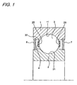
- Fig. 1 is a schematic sectional view in the axial direction of a ball bearing which is the first embodiment of the rolling bearing of the present invention.
- This ball bearing pivotally supports a drive shaft of a liquid crystal device and is installed in an environment in which water is being scattered outside the ball bearing.
- This ball bearing includes: an outer ring 1 which is a bearing ring; an inner ring 2 which is a bearing ring; a plurality of balls 3 which are rolling elements; a cage 4 for holding the balls 3; a first shielding plate 6; and a second shielding plate 7.
- the outer ring 1 includes: a raceway groove 11 which is formed on an inner circumferential face of the outer ring 1 and used as a raceway surface; a first shielding plate attaching groove, the shape of which is annular; and a second shielding plate attaching groove, the shape of which is annular.
- the raceway groove 11 is located in a central portion in the axial direction on the inner circumferential face.
- the first shielding plate attaching groove is located in one end portion in the axial direction on the inner circumferential face.
- the second shielding plate attaching groove is located in the other end portion in the axial direction on the inner circumferential face.
- the inner ring 2 includes a raceway groove 21 which is a raceway surface and formed in a central portion on the outer circumferential face.
- the plurality of balls 3 are arranged between the raceway groove 11 of the outer ring 1 and the raceway groove 21 of the inner ring 2 in the circumferential direction at regular intervals being held by the cage 4.
- the cage 4 is made of PEEK resin (polyether etherketon) or PPS resin (polyphenylene sulfide).
- the cage 4 includes a pocket 25 for accommodating the balls 3.
- the balls 3 are guided by the ball guide face 28 of the pocket 25.
- the first shielding plate 6 airtightly closes one opening in the axial direction between the outer ring 1 and the inner ring 2.
- One end portion outward in the radial direction of the first shielding plate 6 is fixed into the first shielding plate attaching groove.
- the other end portion inward in the radial direction is opposed to the outer circumferential face of the inner ring 2 while leaving a small gap in the radial direction.
- the other end portion inward in the radial direction of the first shielding plate 6 and a portion on the outer circumferential face of the inner ring 2, which is opposed to this other end portion in the radial direction, form a labyrinth seal.
- the second shielding plate 7 airtightly closes one opening in the axial direction between the outer ring 1 and the inner ring 2.
- One end portion outward in the radial direction of the second shielding plate 7 is fixed into the second shielding plate attaching groove.
- the other end portion inward in the radial direction is opposed to the outer circumferential face of the inner ring 2 while leaving a small gap in the radial direction.
- the other end portion inward in the radial direction of the second shielding plate 7 and a portion on the outer circumferential face of the inner ring 2, which is opposed to this other end portion in the radial direction form a labyrinth seal. Inside the ball bearing, water, which has passed through the labyrinth seal, are scattering at the time of using the ball bearing.
- the raceway groove 11 of the outer ring 1, the raceway groove 21 of the inner ring 2, the surface (the rolling contact surface) of each ball 3 and all the surface of the cage 4 are coated with titanium oxide which is an example of the hydrophilic material.
- the surfaces of the raceway groove 11 of the outer ring 1, the raceway groove 21 of the inner ring 1, each ball 3 and cage 4 have hydrophilic layers (not shown) made of titanium oxide.
- the raceway grooves 11, 21 of the inner and outer rings 1, 2, the surfaces of the balls 3 (the rolling contact surfaces) and the ball guide face 28 of the pocket 25 of the cage 4 have hydrophilic layers made of titanium oxide having a hydrophilic property.
- water is scattering in the ball bearing. Therefore, it is possible to retain the scattering water by this hydrophilic layer.
- titanium oxide is used as material having a hydrophilic property.
- a compound material containing titanium oxide, polyoxysilyl compound and material having a hydroxyl group such as polypropylene is used as hydrophilic material.
- any material may be used.
- the raceway grooves 11, 21 of the inner and outer rings 1, 2, the rolling contact surfaces of the balls 3 and all the surface of the cage 4 are coated with titanium oxide which is an example of the hydrophilic material.
- at least one of the raceway surface of the bearing ring, the rolling contact surface of the rolling element and the guide surface of the pocket of the cage for guiding the rolling element may be coated with titanium oxide.
- the lubricating property of at least one of the raceway surface of the bearing ring, the rolling contact surface of the rolling element and the guide surface of the pocket of the cage for guiding the rolling element, which are coated with hydrophilic material can be made excellent over a long period of time.
- the rolling element is the ball 3.
- the rolling element may be a cylindrical roller, a tapered roller or a spherical roller, that is, the rolling element may be a rolling element except for a ball.
- the shielding plates 6, 7 are arranged on both sides in the axial direction between the outer ring 1 and the inner ring 2, that is, one shielding plate is arranged on each side.
- the seal device is not limited to the shielding plate but the seal device may be a seal device having a sliding contact lip formed out of a core bar and an elastic portion.
- the seal device is not limited to the outer ring fixing type described in the present embodiment but the seal device may be of the inner ring fixing type.
- the seal member may be arranged only on one side in the axial direction between the outer ring and the inner ring. A portion between the inner and the outer ring may not be airtightly closed by the seal device.
- titanium oxide is employed as hydrophilic material.
- the contamination attached to the hydrophilic layer can be dissolved into carbon dioxide by the photocatalystic action of titanium oxide. Accordingly, in this case, the hydrophilic layer can be washed and maintained in a clean condition.
- all the surface of the cage 4 is coated with hydrophilic material. Further, in the ball bearing of the first embodiment, as shown in Fig. 1 , at the time of using the ball bearing, the cage 4 is located leaving an interval with respect to the outer ring 1 and the inner ring 2. Therefore, an end face outward in the radial direction of the cage 4, which is shown by the reference numeral 30 in Fig. 1 , that is, a portion not coming into sliding contact with other members is not necessarily coated with hydrophilic material. However, when all the surface of the cage is coated with hydrophilic material, it is possible to execute coating simply and quickly as compared with a case in which a portion of the surface of the cage is coated with hydrophilic material.
- the ball bearing of the present invention is mounted on a drive shaft of a liquid crystal device.
- the rolling bearing of the present invention can be mounted on not only the liquid crystal device but also any device such as a washing device used in an environment in which water, steam or chemical fluid containing water is scattering outside the bearing.
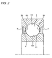
- Fig. 2 is a schematic sectional view in the axial direction of a ball bearing which is the second embodiment of the rolling bearing of the present invention.
- This ball bearing of the second embodiment is different from that of the first embodiment as follows.
- the raceway groove 111 of the outer ring 101 and the raceway groove 121 of the inner ring 102 are not coated with hydrophilic material such as titanium oxide but coated with solid lubricant.
- the other constitution is the same as that of the ball bearing of the first embodiment.
- Examples of the above solid lubricant are: graphite, graphite fluoride, carbon fluoride, hexagonal boron nitride, mica fluoride, gold, silver, lead, magnesium, tungsten disulfide, molybdenum disulfide, graphite, tetrafluoride ethylene, Teflon, PFA, MoS 2 , WS 2 and mixtures of them.
- the rolling contact surface of the ball 3 and the ball guide surface 28 of the pocket of the cage 4 are coated with titanium oxide having a hydrophilic property.
- the raceway grooves 111, 121 of the inner and outer rings 101, 102 and a portion not having a hydrophilic property of the rolling contact surface of the ball 3, that is, the raceway grooves 111, 121 of the inner and outer rings 101, 102 are coated with the solid lubricant.
- At least one of the raceway grooves of the inner and outer ring, the rolling contact surface of the ball and the guide surface of the pocket of the cage may be coated with a hydrophilic material.
- a hydrophilic material A case in which only the raceway grooves of the inner and outer rings are coated with hydrophilic material is excluded and a case in which all are coated with hydrophilic material is also excluded.
- members not coated with hydrophilic material in the raceway grooves of the inner and outer rings and the rolling contact face of the ball may be coated with solid lubricant.
- At least one of the raceway grooves of the inner and outer ring, the rolling contact surface of the ball and the guide surface of the pocket of the cage may be coated with a hydrophilic material.
- a hydrophilic material A case in which only the raceway grooves of the inner and outer rings are coated with hydrophilic material is excluded and a case in which all are coated with hydrophilic material is also excluded.
- members not coated with hydrophilic material in the raceway grooves of the inner and outer rings, the rolling contact face of the ball and the ball guide face of the pocket of the cage may be coated with solid lubricant. Due to the foregoing, all of the raceway grooves of the inner and outer ring, the rolling contact surface of the ball and the guide surface of the pocket of the cage can be preferably lubricated.
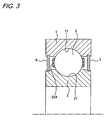
- Fig. 3 is a schematic sectional view in the axial direction of a ball bearing which is the third embodiment of the rolling bearing of the present invention.
- the ball bearing of the third embodiment is different from that of the first embodiment as follows.
- a surface of the cage 204 is not coated with hydrophilic material.
- the ball bearing of the third embodiment employs a cage 204 made of material to which solid lubricant is added or alternatively the ball bearing of the third embodiment employs a cage 204 made of fluororesin having a lubricating property.
- examples of the material to which the solid lubricant is added are: polyamide, polyimide and phenol resin containing the solid lubricant such as molybdenum disulfide enumerated in the second embodiment.
- fluororesin having a lubricating property examples include: tetraethlylene fluoride (polytetrafluoroethylene), teraethylene fluoride-hexapropylenefluoride copolymer (FEP), tetraethylene fluoride-perfluoroalkylvinylether copolymer resin (PFA), tetraethylene fluoride-ethylene copolymer (ETFE), trifluoride ethylenechloride (PCTFE) and vinylidene fluoride (PVDF).
- polytetraethlylene fluoride polytetrafluoroethylene
- FEP teraethylene fluoride-hexapropylenefluoride copolymer
- PFA tetraethylene fluoride-perfluoroalkylvinylether copolymer resin
- ETFE tetraethylene fluoride-ethylene copolymer
- PCTFE trifluoride ethylenechloride
- PVDF vinylidene fluoride
- the cage 204 is made of material, to which solid lubricant is added, or fluororesin having a property of lubrication. Therefore, when the ball 3 is rolled at the time of using the ball bearing, the solid lubricant or the fluororesin is transferred onto the rolling contact surface of the ball 3 or the raceway surfaces of the inner and outer rings 1, 2. Therefore, a lubricant film is formed in a portion to which the solid lubricant or the fluororesin has been transferred.
- the lubrication property can be remarkably enhanced beyond estimation as compared with the rolling bearing, the cage of which is made of the material to which the solid lubricant is added or made of the fluororesin having a lubricating property.
- the hydrophilic material is not coated on the cage at all.
- a portion of the surface of the cage (for example, only the rolling element guide surface of the cage) may be coated with hydrophilic material such as titanium oxide.
- the present invention includes a rolling bearing in which the material of the cage is changed from PEEK resin (polyether etherketon) or PPS resin (polyphenylene sulfide) to the material to which the solid lubricant is added or to the fluororesin having a lubricating property in the rolling bearing of the first embodiment, the rolling bearing of the variation of the first embodiment, the second embodiment or the rolling bearing the variation of the second embodiment.
- PEEK resin polyether etherketon
- PPS resin polyphenylene sulfide
Landscapes
- Engineering & Computer Science (AREA)
- General Engineering & Computer Science (AREA)
- Mechanical Engineering (AREA)
- Rolling Contact Bearings (AREA)
Abstract
Description
- The present invention relates to a rolling bearing. More particularly, the present invention relates to a rolling bearing used in an environment in which water, steam or chemical fluid containing water is scattering. Especially, the present invention relates to a rolling bearing preferably used for a liquid crystal device or a washing device.
- Conventionally, in the case where the rolling bearing is used in an environment in which water or liquid containing water is scattering, it is used under the condition of no lubrication or alternatively it is used being lubricated by solid lubricant.
- However, it is clear that the rolling bearing is used under the condition of no lubrication. Even in the case where the rolling bearing is lubricated by solid lubricant, since the solid lubricant functions as lubricant when it is abraded. Therefore, when all the solid lubricant has been abraded, the lubricating function is lost. See, for example,
JP-A-9-42296 - An object of the present invention is to provide a rolling bearing capable of being positively lubricated over a long period of time in an environment in which water, steam or chemical fluid containing water is scattering.
- In order to accomplish the above object, a rolling bearing of the present invention comprises: a bearing ring; a rolling element; and a cage, wherein
at least one of the raceway surface of the bearing ring, the rolling contact surface of the rolling element and the guide face of the pocket of the cage for guiding the rolling element has a hydrophilic layer made of material having a hydrophilic property, and
lubrication is made with water retained by the hydrophilic layer. - Examples of the material having the hydrophilic property are: titanium oxide, material containing titanium oxide, polyoxysilyl compound and material having a hydroxyl group such as polypropylene.
- According to the present invention, at least one of the raceway surface of the bearing ring, the rolling contact surface of the rolling element and the guide face of the pocket of the cage has a hydrophilic layer made of material having a hydrophilic property. Therefore, it is possible to retain scattering water by this hydrophilic layer. Accordingly, it is possible to lubricate the rolling bearing by the thus retained water.
- Accordingly, when this rolling bearing is used in an environment in which water, steam or chemical fluid containing water is scattering, the hydrophilic layer and a portion, which comes into sliding contact with the hydrophilic layer, can be always lubricated by water. Therefore, the hydrophilic layer and the portion, which comes into sliding contact with the hydrophilic layer, can be put into an excellent lubricating condition at all times while the rolling bearing is being used.
- In the case of a constitution in which titanium oxide or material containing titanium oxide is used as hydrophilic material and further no sealing member is provided in the rolling bearing, that is, in an environment in which the sunlight and ultraviolet rays can intrude into the rolling bearing, the contamination attached to the hydrophilic layer can be dissolved into carbon dioxide by the photocatalystic action of titanium oxide. Accordingly, the hydrophilic layer can be washed and maintained in a clean condition.
- In one embodiment, no hydrophilic layer is provided in a portion of the raceway surface of the bearing ring and the rolling contact surface of the rolling element. This portion has a solid lubricating layer made of solid lubricant.
- According to the above embodiment, no hydrophilic layer is provided in a portion of the raceway surface of the bearing ring and the rolling contact surface of the rolling element. This portion has a solid lubricating layer made of solid lubricant. Therefore, until the solid lubricant is abraded away, all the raceway surface of the bearing ring and the rolling contact surface of the rolling element can be lubricated in a good condition.
- In one embodiment, the cage is made of material added with solid lubricant or made of fluororesin having a lubrication property.
- According to the above embodiment, by the synergistic effect of the lubricating actions of the hydrophilic layer and the cage, the lubricating property can be greatly enhanced beyond estimation as compared with a rolling bearing, the cage of which is made of material to which the solid lubricant is added, or material of fluororesin having a lubricating property.
- According to the rolling element of the present invention, the hydrophilic layer and the portion, which comes into sliding contact with the hydrophilic layer, can be always lubricated by water. Therefore, the hydrophilic layer and the portion, which comes into sliding contact with the hydrophilic layer, can be put into an excellent lubricating condition at all times while the rolling bearing is being used.
-
-
Fig. 1 is a schematic sectional view showing a ball bearing of the first embodiment of the present invention. -
Fig. 2 is a schematic sectional view showing a ball bearing of the second embodiment of the present invention. -
Fig. 3 is a schematic sectional view showing a ball bearing of the third embodiment of the present invention. - An embodiment of the present invention will be explained in detail, referring to the drawings.
-
Fig. 1 is a schematic sectional view in the axial direction of a ball bearing which is the first embodiment of the rolling bearing of the present invention. - This ball bearing pivotally supports a drive shaft of a liquid crystal device and is installed in an environment in which water is being scattered outside the ball bearing.
- This ball bearing includes: an
outer ring 1 which is a bearing ring; aninner ring 2 which is a bearing ring; a plurality ofballs 3 which are rolling elements; acage 4 for holding theballs 3; afirst shielding plate 6; and asecond shielding plate 7. - The
outer ring 1 includes: araceway groove 11 which is formed on an inner circumferential face of theouter ring 1 and used as a raceway surface; a first shielding plate attaching groove, the shape of which is annular; and a second shielding plate attaching groove, the shape of which is annular. Theraceway groove 11 is located in a central portion in the axial direction on the inner circumferential face. The first shielding plate attaching groove is located in one end portion in the axial direction on the inner circumferential face. The second shielding plate attaching groove is located in the other end portion in the axial direction on the inner circumferential face. - The
inner ring 2 includes araceway groove 21 which is a raceway surface and formed in a central portion on the outer circumferential face. - The plurality of
balls 3 are arranged between theraceway groove 11 of theouter ring 1 and theraceway groove 21 of theinner ring 2 in the circumferential direction at regular intervals being held by thecage 4. Thecage 4 is made of PEEK resin (polyether etherketon) or PPS resin (polyphenylene sulfide). Thecage 4 includes apocket 25 for accommodating theballs 3. Theballs 3 are guided by theball guide face 28 of thepocket 25. - The
first shielding plate 6 airtightly closes one opening in the axial direction between theouter ring 1 and theinner ring 2. One end portion outward in the radial direction of thefirst shielding plate 6 is fixed into the first shielding plate attaching groove. On the other hand, the other end portion inward in the radial direction is opposed to the outer circumferential face of theinner ring 2 while leaving a small gap in the radial direction. The other end portion inward in the radial direction of thefirst shielding plate 6 and a portion on the outer circumferential face of theinner ring 2, which is opposed to this other end portion in the radial direction, form a labyrinth seal. - The
second shielding plate 7 airtightly closes one opening in the axial direction between theouter ring 1 and theinner ring 2. One end portion outward in the radial direction of thesecond shielding plate 7 is fixed into the second shielding plate attaching groove. On the other hand, the other end portion inward in the radial direction is opposed to the outer circumferential face of theinner ring 2 while leaving a small gap in the radial direction. The other end portion inward in the radial direction of thesecond shielding plate 7 and a portion on the outer circumferential face of theinner ring 2, which is opposed to this other end portion in the radial direction, form a labyrinth seal. Inside the ball bearing, water, which has passed through the labyrinth seal, are scattering at the time of using the ball bearing. - The raceway groove 11 of the
outer ring 1, the raceway groove 21 of theinner ring 2, the surface (the rolling contact surface) of eachball 3 and all the surface of thecage 4 are coated with titanium oxide which is an example of the hydrophilic material. In other words, the surfaces of theraceway groove 11 of theouter ring 1, the raceway groove 21 of theinner ring 1, eachball 3 andcage 4 have hydrophilic layers (not shown) made of titanium oxide. - According to the ball bearing of the first embodiment described above, the raceway grooves 11, 21 of the inner and
outer rings ball guide face 28 of thepocket 25 of thecage 4 have hydrophilic layers made of titanium oxide having a hydrophilic property. At the time of using the ball bearing, water is scattering in the ball bearing. Therefore, it is possible to retain the scattering water by this hydrophilic layer. By the thus retained water, it is possible to lubricate theraceway grooves outer rings pocket 25 of thecage 4. Therefore, seizure of the sliding portion can be positively prevented over a long period of time. - In the ball bearing of the first embodiment described above, titanium oxide is used as material having a hydrophilic property. However, in the present invention, it is possible to use a compound material containing titanium oxide, polyoxysilyl compound and material having a hydroxyl group such as polypropylene as hydrophilic material. In this rolling bearing, as long as the material is hydrophilic, any material may be used.
- According to the ball bearing of the first embodiment described above, the
raceway grooves outer rings balls 3 and all the surface of thecage 4 are coated with titanium oxide which is an example of the hydrophilic material. However, in the present invention, at least one of the raceway surface of the bearing ring, the rolling contact surface of the rolling element and the guide surface of the pocket of the cage for guiding the rolling element may be coated with titanium oxide. In this case, the lubricating property of at least one of the raceway surface of the bearing ring, the rolling contact surface of the rolling element and the guide surface of the pocket of the cage for guiding the rolling element, which are coated with hydrophilic material, can be made excellent over a long period of time. - In the ball bearing of the first embodiment described above, the rolling element is the
ball 3. However, in the present invention, the rolling element may be a cylindrical roller, a tapered roller or a spherical roller, that is, the rolling element may be a rolling element except for a ball. - In the ball bearing of the first embodiment described above, the
shielding plates outer ring 1 and theinner ring 2, that is, one shielding plate is arranged on each side. However, in the present invention, the seal device is not limited to the shielding plate but the seal device may be a seal device having a sliding contact lip formed out of a core bar and an elastic portion. In the present invention, the seal device is not limited to the outer ring fixing type described in the present embodiment but the seal device may be of the inner ring fixing type. The seal member may be arranged only on one side in the axial direction between the outer ring and the inner ring. A portion between the inner and the outer ring may not be airtightly closed by the seal device. - In this connection, in the case where the seal device is arranged only on one side in the axial direction between the outer and the inner ring and in the case where no seal device is provided between the outer and the inner ring, titanium oxide is employed as hydrophilic material. Further, in the case of an environment in which the sunlight or ultraviolet rays intrude into between the inner and the outer ring, the contamination attached to the hydrophilic layer can be dissolved into carbon dioxide by the photocatalystic action of titanium oxide. Accordingly, in this case, the hydrophilic layer can be washed and maintained in a clean condition.
- In the ball bearing of the first embodiment, all the surface of the
cage 4 is coated with hydrophilic material. Further, in the ball bearing of the first embodiment, as shown inFig. 1 , at the time of using the ball bearing, thecage 4 is located leaving an interval with respect to theouter ring 1 and theinner ring 2. Therefore, an end face outward in the radial direction of thecage 4, which is shown by thereference numeral 30 inFig. 1 , that is, a portion not coming into sliding contact with other members is not necessarily coated with hydrophilic material. However, when all the surface of the cage is coated with hydrophilic material, it is possible to execute coating simply and quickly as compared with a case in which a portion of the surface of the cage is coated with hydrophilic material. For example, in the case of a rolling bearing, in which the cage comes into slide contact with a circumferential face of the bearing ring, such as a rolling bearing in which the cage is guided by a raceway shoulder portion of the outer ring or the inner ring, when all the surface of the cage is coated with hydrophilic material, it is possible to prevent the seizure of the cage and the circumferential surface of the inner ring or the outer ring by which the cage is guided. - In the present embodiment, the ball bearing of the present invention is mounted on a drive shaft of a liquid crystal device. However, the rolling bearing of the present invention can be mounted on not only the liquid crystal device but also any device such as a washing device used in an environment in which water, steam or chemical fluid containing water is scattering outside the bearing.
-
Fig. 2 is a schematic sectional view in the axial direction of a ball bearing which is the second embodiment of the rolling bearing of the present invention. - Like reference numerals are used to indicate like components in the ball bearings of the first and the second embodiment and the duplicate explanations are omitted here. In the ball bearing of the second embodiment, concerning the same operational effects as those of the ball bearing of the first embodiment and concerning the variation, the explanations are omitted here. Only the constitution and the operational effects different from those of the ball bearing of the first embodiment and the variation will be explained here.
- This ball bearing of the second embodiment is different from that of the first embodiment as follows. The
raceway groove 111 of theouter ring 101 and theraceway groove 121 of theinner ring 102 are not coated with hydrophilic material such as titanium oxide but coated with solid lubricant. The other constitution is the same as that of the ball bearing of the first embodiment. - Examples of the above solid lubricant are: graphite, graphite fluoride, carbon fluoride, hexagonal boron nitride, mica fluoride, gold, silver, lead, magnesium, tungsten disulfide, molybdenum disulfide, graphite, tetrafluoride ethylene, Teflon, PFA, MoS2, WS2 and mixtures of them.
- According to the ball bearing of the second embodiment described above, the
raceway grooves outer rings ball 3, that is, theraceway grooves outer rings raceway grooves outer rings raceway grooves outer rings balls 3 can be excellently lubricated. - In the ball bearing of the second embodiment described above, the rolling contact surface of the
ball 3 and the ball guidesurface 28 of the pocket of thecage 4 are coated with titanium oxide having a hydrophilic property. On the other hand, theraceway grooves outer rings ball 3, that is, theraceway grooves outer rings - However, in the present invention, at least one of the raceway grooves of the inner and outer ring, the rolling contact surface of the ball and the guide surface of the pocket of the cage may be coated with a hydrophilic material. (A case in which only the raceway grooves of the inner and outer rings are coated with hydrophilic material is excluded and a case in which all are coated with hydrophilic material is also excluded.) At the same time, members not coated with hydrophilic material in the raceway grooves of the inner and outer rings and the rolling contact face of the ball may be coated with solid lubricant.
- In the present invention, at least one of the raceway grooves of the inner and outer ring, the rolling contact surface of the ball and the guide surface of the pocket of the cage may be coated with a hydrophilic material. (A case in which only the raceway grooves of the inner and outer rings are coated with hydrophilic material is excluded and a case in which all are coated with hydrophilic material is also excluded.) At the same time, members not coated with hydrophilic material in the raceway grooves of the inner and outer rings, the rolling contact face of the ball and the ball guide face of the pocket of the cage may be coated with solid lubricant. Due to the foregoing, all of the raceway grooves of the inner and outer ring, the rolling contact surface of the ball and the guide surface of the pocket of the cage can be preferably lubricated.
-
Fig. 3 is a schematic sectional view in the axial direction of a ball bearing which is the third embodiment of the rolling bearing of the present invention. - Like reference numerals are used to indicate like components in the ball bearings of the first and the third embodiment and the duplicate explanations are omitted here. In the ball bearing of the third embodiment, concerning the same operational effects as those of the ball bearing of the first embodiment and concerning the variation, the explanations are omitted here. Only the constitution and the operational effects different from those of the ball bearing of the first embodiment and the variation will be explained here.
- The ball bearing of the third embodiment is different from that of the first embodiment as follows. In ball bearing of the third embodiment, a surface of the
cage 204 is not coated with hydrophilic material. On the other hand, the ball bearing of the third embodiment employs acage 204 made of material to which solid lubricant is added or alternatively the ball bearing of the third embodiment employs acage 204 made of fluororesin having a lubricating property. - In this case, examples of the material to which the solid lubricant is added are: polyamide, polyimide and phenol resin containing the solid lubricant such as molybdenum disulfide enumerated in the second embodiment.
- Examples of the fluororesin having a lubricating property are: tetraethlylene fluoride (polytetrafluoroethylene), teraethylene fluoride-hexapropylenefluoride copolymer (FEP), tetraethylene fluoride-perfluoroalkylvinylether copolymer resin (PFA), tetraethylene fluoride-ethylene copolymer (ETFE), trifluoride ethylenechloride (PCTFE) and vinylidene fluoride (PVDF).
- According to the ball bearing of the third embodiment, the
cage 204 is made of material, to which solid lubricant is added, or fluororesin having a property of lubrication. Therefore, when theball 3 is rolled at the time of using the ball bearing, the solid lubricant or the fluororesin is transferred onto the rolling contact surface of theball 3 or the raceway surfaces of the inner andouter rings - In the third embodiment described above, the hydrophilic material is not coated on the cage at all. However, in the present invention, a portion of the surface of the cage (for example, only the rolling element guide surface of the cage) may be coated with hydrophilic material such as titanium oxide.
- In this connection, of course, the present invention includes a rolling bearing in which the material of the cage is changed from PEEK resin (polyether etherketon) or PPS resin (polyphenylene sulfide) to the material to which the solid lubricant is added or to the fluororesin having a lubricating property in the rolling bearing of the first embodiment, the rolling bearing of the variation of the first embodiment, the second embodiment or the rolling bearing the variation of the second embodiment.
Claims (4)
- A rolling bearing comprising:a bearing ring; a rolling element; and a cage,wherein at least one of a raceway surface of the bearing ring, a rolling contact surface of the rolling element and a guide face of a pocket of the cage for guiding the rolling element has a hydrophilic layer made of a material having a hydrophilic property, andlubrication is made with water retained by the hydrophilic layer.
- The rolling bearing according to claim 1, wherein the raceway surface of the bearing ring or the rolling contact surface of the rolling element includes a portion not having the hydrophilic layer and said portion includes a solid lubrication layer made of a solid lubricant.
- The rolling bearing according to claim 1, wherein the cage is made of a material added with solid lubricant or made of fluororesin having a lubrication property.
- The rolling bearing according to claim 1, wherein at least one of the raceway surface of the bearing ring, the rolling contact surface of the rolling element and the guide face of the pocket of the cage is coated with titanium oxide.
Applications Claiming Priority (1)
| Application Number | Priority Date | Filing Date | Title |
|---|---|---|---|
| JP2007295631A JP5272381B2 (en) | 2007-11-14 | 2007-11-14 | Rolling bearing |
Publications (3)
| Publication Number | Publication Date |
|---|---|
| EP2060812A2 true EP2060812A2 (en) | 2009-05-20 |
| EP2060812A3 EP2060812A3 (en) | 2012-12-05 |
| EP2060812B1 EP2060812B1 (en) | 2015-01-07 |
Family
ID=40398199
Family Applications (1)
| Application Number | Title | Priority Date | Filing Date |
|---|---|---|---|
| EP08019296.6A Not-in-force EP2060812B1 (en) | 2007-11-14 | 2008-11-04 | Rolling bearing |
Country Status (3)
| Country | Link |
|---|---|
| US (1) | US8113717B2 (en) |
| EP (1) | EP2060812B1 (en) |
| JP (1) | JP5272381B2 (en) |
Families Citing this family (3)
| Publication number | Priority date | Publication date | Assignee | Title |
|---|---|---|---|---|
| US8380362B2 (en) * | 2009-07-10 | 2013-02-19 | The Boeing Company | Systems and methods for remotely collaborative vehicles |
| DE102009036856A1 (en) * | 2009-08-10 | 2011-02-17 | Magna Steyr Fahrzeugtechnik Ag & Co. Kg | Electric machine with anti-electric shock protected rolling bearing and geared motor with such |
| US9528592B2 (en) | 2012-06-26 | 2016-12-27 | Kinetech Power Company Llc | Solid-lubricated bearing assembly |
Citations (1)
| Publication number | Priority date | Publication date | Assignee | Title |
|---|---|---|---|---|
| JPH0942296A (en) | 1995-07-31 | 1997-02-10 | Nippon Seiko Kk | Corrosion resistant rolling bearing |
Family Cites Families (30)
| Publication number | Priority date | Publication date | Assignee | Title |
|---|---|---|---|---|
| JPH0637897B2 (en) * | 1985-08-23 | 1994-05-18 | 光洋精工株式会社 | Rolling bearing |
| JPH01210618A (en) * | 1988-02-16 | 1989-08-24 | Shizuo Kashima | Bearing coated with ceramics |
| US5066145A (en) * | 1989-06-29 | 1991-11-19 | Tribology Systems, Inc. | Solid-lubricated bearing assembly |
| US5112146A (en) * | 1991-07-17 | 1992-05-12 | Rockwell International Corporation | Functionally gradated rolling element bearing races |
| US5520467A (en) * | 1993-09-09 | 1996-05-28 | Ngk Ltd. | Rolling bearing for use in molten metal |
| JPH0784085A (en) * | 1993-09-20 | 1995-03-31 | Toshiba Corp | Thrust bearing device for internal pump |
| JP3785198B2 (en) * | 1993-12-27 | 2006-06-14 | 株式会社ジェイテクト | Rolling bearing |
| NL9302277A (en) * | 1993-12-28 | 1995-07-17 | Skf Ind Trading & Dev | Water-repellent filter seal. |
| NL9401234A (en) * | 1994-07-27 | 1996-03-01 | Skf Ind Trading & Dev | Roller bearing with a low friction lining. |
| JPH08232961A (en) * | 1995-02-28 | 1996-09-10 | Nippon Seiko Kk | Rolling bearing |
| JPH11125257A (en) * | 1997-08-19 | 1999-05-11 | Nippon Seiko Kk | Rolling bearing device |
| JPH11190335A (en) * | 1997-12-26 | 1999-07-13 | Matsushita Electric Ind Co Ltd | Bearing device and sliding device with excellent slidability |
| NL1009170C2 (en) * | 1998-05-14 | 1999-11-16 | Skf Eng & Res Centre Bv | Coated rolling bearing. |
| JP3761718B2 (en) * | 1998-06-19 | 2006-03-29 | 株式会社ジェイテクト | Rolling bearing |
| JP2000035043A (en) * | 1998-07-16 | 2000-02-02 | Nippon Seiko Kk | Rolling bearing |
| JP2000240666A (en) * | 1998-09-08 | 2000-09-05 | Nsk Ltd | Rolling bearing |
| JP2001087361A (en) * | 1999-09-27 | 2001-04-03 | Max Co Ltd | Photocatalyst type air cleaner |
| JP2002054637A (en) * | 2000-03-30 | 2002-02-20 | Nsk Ltd | Rolling device |
| WO2002008623A1 (en) * | 2000-07-18 | 2002-01-31 | Nsk Ltd. | Rolling apparatus |
| JP3981801B2 (en) * | 2000-08-14 | 2007-09-26 | 日本精工株式会社 | Lubricating oil-containing polymer and rolling bearing |
| JP2002327756A (en) * | 2001-04-27 | 2002-11-15 | Ntn Corp | Solid lubricated rolling bearing |
| JP3988478B2 (en) * | 2002-02-15 | 2007-10-10 | 株式会社ジェイテクト | Rolling bearing |
| JP2004084873A (en) * | 2002-08-28 | 2004-03-18 | Nsk Ltd | Rolling device |
| JP2005069439A (en) * | 2003-08-27 | 2005-03-17 | Yoshiteru Kitahama | Roller bearing and bearing device |
| JP2005097401A (en) * | 2003-09-24 | 2005-04-14 | Matsushita Electric Ind Co Ltd | Sliding coating and its manufacturing method |
| JP2005188651A (en) * | 2003-12-25 | 2005-07-14 | Yamada Seisakusho Co Ltd | Mechanical seal in water pump |
| JP2006046432A (en) * | 2004-08-03 | 2006-02-16 | Koyo Seiko Co Ltd | Rolling sliding member and rolling device equipped therewith |
| JP4484051B2 (en) * | 2004-10-04 | 2010-06-16 | 株式会社ジェイテクト | Rolling bearing |
| JP2006220240A (en) * | 2005-02-14 | 2006-08-24 | Ishikawajima Harima Heavy Ind Co Ltd | Cryogenic ultra high speed rolling bearing |
| JP4536667B2 (en) * | 2006-02-13 | 2010-09-01 | 公立大学法人高知工科大学 | Bearing structure with controlled flow correction factor |
-
2007
- 2007-11-14 JP JP2007295631A patent/JP5272381B2/en not_active Expired - Fee Related
-
2008
- 2008-11-04 US US12/289,784 patent/US8113717B2/en not_active Expired - Fee Related
- 2008-11-04 EP EP08019296.6A patent/EP2060812B1/en not_active Not-in-force
Patent Citations (1)
| Publication number | Priority date | Publication date | Assignee | Title |
|---|---|---|---|---|
| JPH0942296A (en) | 1995-07-31 | 1997-02-10 | Nippon Seiko Kk | Corrosion resistant rolling bearing |
Also Published As
| Publication number | Publication date |
|---|---|
| EP2060812B1 (en) | 2015-01-07 |
| JP5272381B2 (en) | 2013-08-28 |
| EP2060812A3 (en) | 2012-12-05 |
| US20090123100A1 (en) | 2009-05-14 |
| JP2009121581A (en) | 2009-06-04 |
| US8113717B2 (en) | 2012-02-14 |
Similar Documents
| Publication | Publication Date | Title |
|---|---|---|
| JP2628526B2 (en) | Rolling bearing device | |
| CN106979232B (en) | roller bearing | |
| JP5774395B2 (en) | Rolling bearing device | |
| JP5598075B2 (en) | Rolling bearing device | |
| US20100183759A1 (en) | Roller for Pelleting Mill | |
| EP2060812B1 (en) | Rolling bearing | |
| CN108626251B (en) | rolling bearing | |
| JP2016166625A (en) | Rolling bearing with filter | |
| JP2009121581A5 (en) | ||
| CN105387080A (en) | bearing | |
| JP2012007686A (en) | Rolling bearing device | |
| JP2006207613A (en) | Sealing device for rolling bearing and sealed rolling bearing | |
| CN218325835U (en) | Cartridge seal assemblies and rolling bearings | |
| US3247935A (en) | One-way brake assembly and seal means therefor | |
| JP2008500499A (en) | Spinner-Upper roller for draft mechanism | |
| AU2002329686A1 (en) | Seal and bearing assembly | |
| JPH084773A (en) | Solid lubricating rolling bearing | |
| CN203835972U (en) | Rolling bearing | |
| US20250320897A1 (en) | Cassette seal and rolling bearing | |
| JP2006200733A (en) | Rolling bearing | |
| JP2012172776A (en) | Sealed bearing device | |
| JP2025049974A (en) | BALL BEARING AND METHOD FOR APPLYING GREASE TO BALL BEARING | |
| JP2007127251A (en) | Double-row self-aligning roller bearing | |
| CN110273922B (en) | ball bearing | |
| JPH07190075A (en) | Solid lubrication rolling bearing |
Legal Events
| Date | Code | Title | Description |
|---|---|---|---|
| PUAI | Public reference made under article 153(3) epc to a published international application that has entered the european phase |
Free format text: ORIGINAL CODE: 0009012 |
|
| AK | Designated contracting states |
Kind code of ref document: A2 Designated state(s): AT BE BG CH CY CZ DE DK EE ES FI FR GB GR HR HU IE IS IT LI LT LU LV MC MT NL NO PL PT RO SE SI SK TR |
|
| AX | Request for extension of the european patent |
Extension state: AL BA MK RS |
|
| PUAL | Search report despatched |
Free format text: ORIGINAL CODE: 0009013 |
|
| AK | Designated contracting states |
Kind code of ref document: A3 Designated state(s): AT BE BG CH CY CZ DE DK EE ES FI FR GB GR HR HU IE IS IT LI LT LU LV MC MT NL NO PL PT RO SE SI SK TR |
|
| AX | Request for extension of the european patent |
Extension state: AL BA MK RS |
|
| RIC1 | Information provided on ipc code assigned before grant |
Ipc: F16C 33/44 20060101ALI20121030BHEP Ipc: F16C 33/66 20060101AFI20121030BHEP |
|
| 17P | Request for examination filed |
Effective date: 20130605 |
|
| RBV | Designated contracting states (corrected) |
Designated state(s): AT BE BG CH CY CZ DE DK EE ES FI FR GB GR HR HU IE IS IT LI LT LU LV MC MT NL NO PL PT RO SE SI SK TR |
|
| AKX | Designation fees paid |
Designated state(s): DE FR |
|
| 17Q | First examination report despatched |
Effective date: 20131121 |
|
| GRAP | Despatch of communication of intention to grant a patent |
Free format text: ORIGINAL CODE: EPIDOSNIGR1 |
|
| INTG | Intention to grant announced |
Effective date: 20140728 |
|
| GRAS | Grant fee paid |
Free format text: ORIGINAL CODE: EPIDOSNIGR3 |
|
| GRAA | (expected) grant |
Free format text: ORIGINAL CODE: 0009210 |
|
| AK | Designated contracting states |
Kind code of ref document: B1 Designated state(s): DE FR |
|
| REG | Reference to a national code |
Ref country code: DE Ref legal event code: R096 Ref document number: 602008036199 Country of ref document: DE Effective date: 20150219 |
|
| REG | Reference to a national code |
Ref country code: DE Ref legal event code: R097 Ref document number: 602008036199 Country of ref document: DE |
|
| PLBE | No opposition filed within time limit |
Free format text: ORIGINAL CODE: 0009261 |
|
| STAA | Information on the status of an ep patent application or granted ep patent |
Free format text: STATUS: NO OPPOSITION FILED WITHIN TIME LIMIT |
|
| 26N | No opposition filed |
Effective date: 20151008 |
|
| REG | Reference to a national code |
Ref country code: FR Ref legal event code: ST Effective date: 20160729 |
|
| PG25 | Lapsed in a contracting state [announced via postgrant information from national office to epo] |
Ref country code: FR Free format text: LAPSE BECAUSE OF NON-PAYMENT OF DUE FEES Effective date: 20151130 |
|
| PGFP | Annual fee paid to national office [announced via postgrant information from national office to epo] |
Ref country code: DE Payment date: 20201020 Year of fee payment: 13 |
|
| REG | Reference to a national code |
Ref country code: DE Ref legal event code: R119 Ref document number: 602008036199 Country of ref document: DE |
|
| PG25 | Lapsed in a contracting state [announced via postgrant information from national office to epo] |
Ref country code: DE Free format text: LAPSE BECAUSE OF NON-PAYMENT OF DUE FEES Effective date: 20220601 |