EP2060763A2 - Glitch Detector and Method of Detecting Glitch Events - Google Patents
Glitch Detector and Method of Detecting Glitch Events Download PDFInfo
- Publication number
- EP2060763A2 EP2060763A2 EP08167857A EP08167857A EP2060763A2 EP 2060763 A2 EP2060763 A2 EP 2060763A2 EP 08167857 A EP08167857 A EP 08167857A EP 08167857 A EP08167857 A EP 08167857A EP 2060763 A2 EP2060763 A2 EP 2060763A2
- Authority
- EP
- European Patent Office
- Prior art keywords
- valve
- current
- glitch
- actuator
- detector
- Prior art date
- Legal status (The legal status is an assumption and is not a legal conclusion. Google has not performed a legal analysis and makes no representation as to the accuracy of the status listed.)
- Granted
Links
Images





Classifications
-
- F—MECHANICAL ENGINEERING; LIGHTING; HEATING; WEAPONS; BLASTING
- F02—COMBUSTION ENGINES; HOT-GAS OR COMBUSTION-PRODUCT ENGINE PLANTS
- F02D—CONTROLLING COMBUSTION ENGINES
- F02D41/00—Electrical control of supply of combustible mixture or its constituents
- F02D41/20—Output circuits, e.g. for controlling currents in command coils
-
- F—MECHANICAL ENGINEERING; LIGHTING; HEATING; WEAPONS; BLASTING
- F02—COMBUSTION ENGINES; HOT-GAS OR COMBUSTION-PRODUCT ENGINE PLANTS
- F02D—CONTROLLING COMBUSTION ENGINES
- F02D41/00—Electrical control of supply of combustible mixture or its constituents
- F02D41/20—Output circuits, e.g. for controlling currents in command coils
- F02D2041/202—Output circuits, e.g. for controlling currents in command coils characterised by the control of the circuit
- F02D2041/2055—Output circuits, e.g. for controlling currents in command coils characterised by the control of the circuit with means for determining actual opening or closing time
-
- F—MECHANICAL ENGINEERING; LIGHTING; HEATING; WEAPONS; BLASTING
- F02—COMBUSTION ENGINES; HOT-GAS OR COMBUSTION-PRODUCT ENGINE PLANTS
- F02D—CONTROLLING COMBUSTION ENGINES
- F02D41/00—Electrical control of supply of combustible mixture or its constituents
- F02D41/20—Output circuits, e.g. for controlling currents in command coils
- F02D2041/202—Output circuits, e.g. for controlling currents in command coils characterised by the control of the circuit
- F02D2041/2058—Output circuits, e.g. for controlling currents in command coils characterised by the control of the circuit using information of the actual current value
-
- F—MECHANICAL ENGINEERING; LIGHTING; HEATING; WEAPONS; BLASTING
- F02—COMBUSTION ENGINES; HOT-GAS OR COMBUSTION-PRODUCT ENGINE PLANTS
- F02D—CONTROLLING COMBUSTION ENGINES
- F02D2250/00—Engine control related to specific problems or objectives
- F02D2250/14—Timing of measurement, e.g. synchronisation of measurements to the engine cycle
-
- F—MECHANICAL ENGINEERING; LIGHTING; HEATING; WEAPONS; BLASTING
- F02—COMBUSTION ENGINES; HOT-GAS OR COMBUSTION-PRODUCT ENGINE PLANTS
- F02D—CONTROLLING COMBUSTION ENGINES
- F02D41/00—Electrical control of supply of combustible mixture or its constituents
- F02D41/30—Controlling fuel injection
- F02D41/38—Controlling fuel injection of the high pressure type
- F02D41/40—Controlling fuel injection of the high pressure type with means for controlling injection timing or duration
- F02D41/402—Multiple injections
-
- H—ELECTRICITY
- H01—ELECTRIC ELEMENTS
- H01F—MAGNETS; INDUCTANCES; TRANSFORMERS; SELECTION OF MATERIALS FOR THEIR MAGNETIC PROPERTIES
- H01F7/00—Magnets
- H01F7/06—Electromagnets; Actuators including electromagnets
- H01F7/08—Electromagnets; Actuators including electromagnets with armatures
- H01F7/18—Circuit arrangements for obtaining desired operating characteristics, e.g. for slow operation, for sequential energisation of windings, for high-speed energisation of windings
- H01F7/1844—Monitoring or fail-safe circuits
- H01F2007/1855—Monitoring or fail-safe circuits using a stored table to deduce one variable from another
-
- H—ELECTRICITY
- H01—ELECTRIC ELEMENTS
- H01F—MAGNETS; INDUCTANCES; TRANSFORMERS; SELECTION OF MATERIALS FOR THEIR MAGNETIC PROPERTIES
- H01F7/00—Magnets
- H01F7/06—Electromagnets; Actuators including electromagnets
- H01F7/08—Electromagnets; Actuators including electromagnets with armatures
- H01F7/18—Circuit arrangements for obtaining desired operating characteristics, e.g. for slow operation, for sequential energisation of windings, for high-speed energisation of windings
- H01F7/1844—Monitoring or fail-safe circuits
- H01F2007/1866—Monitoring or fail-safe circuits with regulation loop
-
- H—ELECTRICITY
- H01—ELECTRIC ELEMENTS
- H01F—MAGNETS; INDUCTANCES; TRANSFORMERS; SELECTION OF MATERIALS FOR THEIR MAGNETIC PROPERTIES
- H01F7/00—Magnets
- H01F7/06—Electromagnets; Actuators including electromagnets
- H01F7/08—Electromagnets; Actuators including electromagnets with armatures
- H01F7/18—Circuit arrangements for obtaining desired operating characteristics, e.g. for slow operation, for sequential energisation of windings, for high-speed energisation of windings
- H01F2007/1888—Circuit arrangements for obtaining desired operating characteristics, e.g. for slow operation, for sequential energisation of windings, for high-speed energisation of windings using pulse width modulation
Definitions
- the present invention relates to a glitch detector and method of detecting glitch events. More particularly, the present invention relates to the detection of valve movement of a valve in a fuel injector of an engine system by the detection and analysis of discontinuities ("glitches") in the current through a control actuator of the valve.
- actuator controlled valves e.g. solenoid valves
- solenoid valves are used to control the flow of fuel within the injector, and hence, timing, pressure and quantity of fuel injected into the engine cylinders.
- a single solenoid valve - known as the "Spill Valve” - is used to control the point at which fuel pressure within the injector volume begins to increase. If the valve is open, fuel will be allowed to "spill” to low pressure (the fuel tank). Alternatively, if the valve is closed, the mass of fuel within the injector will undergo pressurisation due to the advancing cam-driven plunger reducing the injector volume. Injection of fuel into the engine's cylinder occurs once the fuel pressure within the injector becomes greater than the spring pressure which holds the injector needle closed against its seat, resulting in "injector needle lift".
- EUIs Electronic Unit Injectors
- EUPs Electronic Unit Pumps
- NOP Nozzle Opening Pressure
- a secondary solenoid valve is used to regulate the control pressure applied to the back of the injector needle and, hence, NOP can exceed the needle spring pressure (i.e. variable NOP).
- This solenoid valve is known as the "Needle Control Valve”. It is a "three-way” valve, in that it exposes the port, the pressure of which is to be controlled, to either a high control pressure (when de-energised) or a drain pressure (when energised).
- This invention refers to the control of both single and twin valve injection systems.
- Valve movement is facilitated by means of an actuator which comprises an electromagnetic stator (a series of coil windings wound around a stator core), through which a current is passed to activate an armature.
- An electromagnetic stator a series of coil windings wound around a stator core
- a valve pin is directly attached to the armature, and subsequent movement of the armature/valve assembly is used to control flow of fuel within the injector.
- the valve pin is held in the open position by a return spring, therefore any electromagnetic force induced by the solenoid coil is working against the spring to close the valve.
- the control of the solenoid valve is divided into two general categories, a so called “pull-in” phase and a “hold phase”.
- the armature of the solenoid-controlled valve is caused to close by the application of a first current level through the solenoid coil.
- a second, lower current level is supplied to the solenoid coil to keep the valve closed.
- the driving current provided during the pull-in phase is supplied by a capacitor.
- the capacitor and associated circuitry provide a further voltage supply means (in addition to the battery) and are hereinafter collectively referred to as the "boost circuit".
- the driving current provided during the hold phase is supplied by applying the standard battery voltage across the solenoid coil in order to provide the second current level.
- a so-called “chopping circuit” controls the application of the battery voltage so that the required drive current supplied to the actuator throughout the injection is between defined upper and lower hold thresholds.
- the chopping circuit may constantly apply the battery voltage to the solenoid coil during the entire hold phase of injection in order to maintain the driving current to the solenoid between the desired threshold levels.
- control system may detect changes in valve performance through the detection of changes in the current profile of the coil used to drive valve motion.
- the current seen on a coil has a characteristic profile due to the induction effect of a decaying magnetic field and a valve moving through that field affects the current profile (this effect is generally termed back EMF).
- this effect is generally termed back EMF.
- the valve when the valve reaches the end of its travel, it will stop moving or bounce off of its seat/stop and this change can be detected as a discontinuity, or "glitch", in the current profile.
- the change in current profile corresponds to the valve meeting its stop and the valve at this point in its actuated state, it follows that what is being detected correlates with the physical events triggered by the actuated valve. Therefore, the change in the characteristic profile of the current provides an effective way to measure the start of injection or pressure rise without reference to external sensors.
- a glitch detection system that is able to reliably and efficiently detect the changes in the current profile can then relate the change in the current profile to physical events such as the start/end of pressure and start/end of injection (delivery). This gives initial performance benefits as well as allowing the system to self correct if there are changes in valve response. It follows that one of the main disadvantages of the system without glitch is that there is no way to control the injector timing to compensate for any changes that occur over the life of the system. It is known that the injector components can undergo two significant changes after installation, namely the bedding in period and wear caused during normal operation. These two conditions mean that the injector performance deviates from the factory set values over its service lifetime.
- Glitch windows may also have the problem that the window position has an influence on the position of the current discontinuity that is recorded.
- any detection routine must be able to rapidly and efficiently evaluate the available data and make a glitch decision in the shortest possible time.
- the detection criteria must be mathematically as simple as possible and be paired with a sufficiently powerful CPU to reduce the negative impacts of having the glitch window in the wrong position.
- a decision on the glitch status should be decided on a shot to shot basis for the best performance benefits.
- glitch window is a deviation from the natural current decay by forced voltage application, there will always be a measured (i.e. non zero) current associated with it.
- a key difficulty in prior art glitch detection systems is discriminating between a valid glitch event and a non valid event. In other words, the detection routine must be able to distinguish the difference between a natural current decay profile and a profile with the effects of a change in motion by the armature.
- a glitch detector for detecting valve movement of a valve in a fuel injector of an engine system, the valve comprising an electromagnetic actuator which is arranged to move the valve between first and second valve positions during a valve cycle and the engine system comprising sensing means for sensing a current through the actuator.
- the detector comprises control means arranged to control the sensing means; inputs for receiving from the sensing means data related to the current through the actuator; a processor arranged to analyse the received data for current discontinuities; outputs for outputting a valve movement signal (e.g. glitch detect signal) in dependence upon the current discontinuities determined by the processor.
- the control means is arranged to enable the sensing means during a finite sampling window and is further arranged (i) to move the sampling window from a first window position for a first injection event to a progressively later window position for one or more subsequent injection events, (ii) to calculate a new sampling window position on the basis of a valve movement signal output for at least two of the preceding window positions, and (iii) to feedback the new sampling window position for a subsequent injection event.
- the present invention provides a glitch detector in which the current through the actuator of a valve in an engine is received from a sensing means and then analysed for discontinuities in the current profile which indicates the presence of a glitch event.
- a control means is arranged to enable the sensing means only during a finite sampling window. Once a current discontinuity has been identified the detector can output a glitch detect signal, which may be a timing signal indicating the end of valve movement. If the detector is able to compare the discrete timing signal to known/expected valve operation then the detector may be able to determine unexpected valve operation.
- the detector may output an error signal that the vehicle's engine control unit (ECU) records or an error signal for display on the dashboard of the vehicle. If the detector is linked to or part of a valve control system then the output signal may be a control signal for adapting the firing characteristics of the injector.
- ECU engine control unit
- Subsequent injection events are preferably either (i) successive injection events or (ii) one of pilot, main or post injection events within successive injection cycles.
- the new sampling window position is calculated as a median position of at least two of the preceding window positions for which a glitch detect signal is output. It may be preferable to calculate the new sampling window position as a median position of three of the preceding window positions.
- the processor is arranged to analyse the current through the actuator during the sampling window and to look for and identify discontinuities in the current flow. Such discontinuities can be linked to, for example, the valve reaching its stop and so the processor is effectively able to determine valve movements in dependence upon measured current discontinuities.
- the sensing means may not directly sense the current through the actuator and may instead sense a parameter that is related to the current through the actuator.
- the drive circuit may comprise a resistor in series with the actuator and the sensing means may measure the voltage across the resistor.
- the sensing means is arranged to sample the current parameter at a plurality of sample points during the sampling window.
- the sensing means may measure the current through a sensing resistor.
- the sensing means may be arranged to sense the current through the actuator.
- the sensing means may comprise a sensing resistor and the data received at the inputs may be related to the current through the sensing resistor or the voltage across the sensing resistor.
- the valve cycle may comprise a pull-in region during which a first voltage potential is applied across the actuator so that the valve is caused to move from a first state to a second state and a hold region during which a second voltage potential or series of pulses at a second voltage potential is applied across the actuator.
- control means may be arranged to enable the sensing means between the pull-in and hold regions of the valve cycle.
- the control means may also be arranged to enable the sensing means after the hold region of the valve cycle. It is noted that these two enablement positions correspond to the points within the valve cycle when the valves within the engine are expected to reach one of their two operating positions.
- control means may conveniently be arranged to output a control signal to one or more control switches in order to isolate the actuator from a power supply and to open a current path comprising the actuator and the current sensing means. It is noted that at the back end of the valve cycle, i.e. after the hold phase, the current through the actuator will fall towards zero. In order to detect the movement of the valve the control means may open a current path that is inactive during the pull-in and hold phases such that a current (which includes the effects from the back EMF in the system) flows through the sensing means/drive circuit.
- control means may be arranged to progressively move the sampling window away from the end of the hold region in successive injection events.
- Effective glitch detection must include as small as possible a processing overhead for noise control. Using a method that relies solely on maxima detection in the current profile is ineffective since every sample will have a maximum that may or may not correspond to a valid glitch event. Using a threshold on the maxima is similarly ineffective since this does not allow for the range of possible valve/coil response patterns.
- the detector may be arranged to analyse the received data by determining the second derivative of the current through the actuator with respect to time.
- the processor may be arranged to determine the presence of a current discontinuity if a maxima or minima is detected in the second derivative of the current through the actuator.
- the second derivative may be calculated based on a differential process for which input data points are non-consecutive. This provides a processing advantage because a mathematical implementation based on a differential implementation is numerically one of the fastest operations that can be performed by a CPU.
- the received data are input to an analysis routine of the processor in the form of integer values having no units, thereby to minimise data handling and manipulation requirements.
- the processor may be arranged to determine the presence of a current discontinuity if the second derivative of the current through the actuator exceeds a threshold value. This enables the detector to "filter out” transient effects within the current profile.
- the second derivative of the current through the actuator should also exceed the threshold value for a set period of time in order for the detector to determine the presence of a current discontinuity. This also helps filter out transient spikes in the profile.
- a method of detecting valve movement of a valve in a fuel injector of an engine system comprising an electromagnetic actuator which is arranged to move the valve between first and second positions during a valve cycle, the method comprising sampling the current through the actuator during a finite sampling window, analyzing the sampled current for current discontinuities, and determining valve movements in dependence upon the current discontinuities.
- the method further comprises moving the sampling window from a first window position for a first injection event to a progressively later window position for one or more subsequent injection events, calculating a new sampling window position on the basis of a valve movement signal (e.g. glitch detect signal) output for at least two of the preceding window positions, and feeding back the new sampling window position for a subsequent injection event.
- a valve movement signal e.g. glitch detect signal
- a glitch detector for detecting valve movement of a valve in a fuel injector of an engine system, the valve comprising an electromagnetic actuator which is arranged to move the valve between first and second positions during a valve cycle.
- the detector comprises inputs for receiving data related to the current through the actuator; a processor arranged to analyse the received data for current discontinuities by determining the second derivative with respect to time of the current through the actuator; and outputs for outputting a valve movement signal (e.g. glitch detect signal) in dependence upon the current discontinuities determined by the processor.
- the processor may be further arranged to calculate the second derivative based on a differential process for which input data points are non-consecutive.
- a method of detecting valve movement of a valve in a fuel injector of an engine system comprising an electromagnetic actuator which is arranged to move the valve between first and second positions during a valve cycle, the method comprising: sampling the current through the actuator in order to determine current data; analyzing the sampled current data for current discontinuities and outputting a valve movement signal in dependence upon the current discontinuities.
- the current data is analysed by determining the second derivative with respect to time of the current through the actuator.
- the second derivative may be calculated based on a differential process for which input data points are non-consecutive.
- This process of differentiation provides a substantially more efficient method than the prior art, in terms of processing and memory resources.
- the method may be further improved by using non-unit delimited input data in the differential process.
- the present invention extends to a carrier medium for carrying a computer readable code for controlling a controller or engine control unit to carry out the method of the second or fourth aspects of the invention and to an engine control unit for a vehicle comprising a detector according to the first or third aspects of the invention.
- Figure 1 is a simple representative sketch showing a voltage waveform V that is applied across an actuator and two current profiles I 1 and I 2 .
- the first current profile I 1 shows the current that flows through the actuator coils as a result of back EMF when there are no sudden changes in the motion of the valve. It can be seen that the current profile is smooth.
- the present invention is concerned with the identification of these types of glitch in the current through the actuator and with the minimisation of the problems associated with known glitch detection methods.
- Figure 2 is a representation of a simple drive circuit 2 for a coil-based actuator 4, i.e. an electromagnetically controlled coil and a glitch detector 6 in accordance with an embodiment of the present invention.
- the circuit comprises a power supply 8 (in this case 50V), a solenoid actuator 4 and a sensing means 10 which comprises a sensing resistor 12.
- a power supply 8 in this case 50V
- a solenoid actuator 4 connects the power supply 8 to the sensing resistor 12 and actuator 4.
- Cross circuit connections 18, 20 are provided each of which comprises a diode 22, 24 to restrict the direction of allowable current flow.
- the glitch detector 6 comprises inputs 26 for receiving data related to the current through the actuator 4, processing means 28, control means 30 for controlling switches 14 and 16 and output means 32 for outputting a valve movement signal.
- the voltage across the sensing resistor can be measured and therefore the current through the solenoid determined.
- the power supply and controllable switches 14 and 16 may be controlled by, for example, an engine control unit (ECU) (not shown in Figure 2 ).
- ECU engine control unit
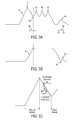
- FIG. 3a A typical current profile 40 representing the current through the actuator 4 during a single combustion cycle is shown in Figure 3a.
- Figure 3b shows the corresponding valve movement 42 as the current varies.
- valve and drive circuit The operation of the valve and drive circuit will now be described with reference to Figures 2 and 3 .
- both switches, 14 and 16 are closed.
- the current through the actuator 4 then rises from zero up to a maximum peak value 44.
- This phase of the injection cycle is referred to as the "pull-in” phase (or alternatively as the "front end").
- switch 14 is opened and the current begins to decay naturally. During this current decay the valve moves such that injection commences. As the current falls to a certain level, switch 14 is repeatedly opened and closed (or “chopped") in order to maintain injection through the activated valve. This chopping is shown by a number of smaller peak values 46, 48, 50 in the current profile. This phase of the injection cycle is known as the "hold" phase.
- switch 16 may be re-opened such that a current path is formed. Due to the effects of the valve moving through the magnetic field created by the actuator coil, a back EMF is set up that either re-enforces the current or partially cancels the current (depending on the direction of motion of the valve). This period of EMF-related current and normal current superposition is shown in Figure 3a (between 52 and 54).
- Figure 3b shows the corresponding valve lift during the current events. When the valve reaches its stop there will be a discontinuity or glitch 56 in the current profile which corresponds to feature 58 in Figure 3a/3b . (It is noted that the valve depicted in Figure 3b undergoes a "bounce" event 59. This type of event can occur in cases of rapid valve timing changes where the valve may effectively bounce).
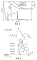
- Figure 4 shows the effect the glitch window may potentially have on the movement of the valve. It is noted that Figure 4 shows a sample window 80 that is too early relative to the movement of the valve.
- the current profile at the end of the hold phase is shown in more detail in Figure 4 .
- a sampling window is also shown during which a current (which includes the effects from the back EMF in the system) flows through the drive circuit.
- the current profile 70 during the sampling window has a characteristic shape.
- a first valve lift line 72 is shown which indicates that the valve should reach its stop position shortly after the end of the sampling window.
- a second valve movement trace 74 depicting the actual valve movement is also shown. This second trace 74 illustrates the effects of the current in reenergising the drive circuit of the valve. It can be seen that the sampling window has the effect of delaying the valve.
- sampling window and method of glitch detection in accordance with a first embodiment of the present invention is shown in Figure 5 .
- the sampling window is not fixed at a certain point in the combustion cycle of the engine but is instead capable of being swept in time between different cycles.
- sampling window locations are depicted relating to a specific injection event (e.g. pre-injection, main injection or post injection) within subsequent injection cycles. It is also noted that the five sampling window locations are arranged to be progressively moved away from the end of the hold region in successive injection cycles. This is done in order to ensure that the first glitch event is detected and to mitigate against the possibility of a secondary glitch event (caused by valve bounce as described) above being misclassified as the primary glitch event.
- a specific injection event e.g. pre-injection, main injection or post injection
- the five sampling window locations are arranged to be progressively moved away from the end of the hold region in successive injection cycles. This is done in order to ensure that the first glitch event is detected and to mitigate against the possibility of a secondary glitch event (caused by valve bounce as described) above being misclassified as the primary glitch event.
- the window 80 starts in an initial position (Position 1), which may be a fixed period of time after the end of the hold period. In this position the current profile 82 resembles the profile of Figure 4 in which the current slowly builds to a maximum at the end of the sampling window before falling away to zero. From the valve movement trace 84 shown in Figure 5 it can be seen that the sampling window's initial position is too early and has missed the "glitch point" 86 (i.e. the valve stop).
- sampling window 80 has been advanced to a later time (Position 2).
- the profile 88 has now changed and the maximum 90 in the current profile is now seen to be located part way through the sampling window 80 (as opposed to at the end of the sampling window as in the first position). It is clear that the sampling window has "found" the glitch 86.
- the sampling window 80 has been moved past the first glitch event 86.
- the current profile 96 in Position 4 shows no evidence of a current discontinuity but the current profile 98 in Position 5 shows a further discontinuity 100 which represents a secondary valve stop event 102 (it is noted that in cases of rapid valve timing changes the valve may effectively bounce and so there will be a secondary glitch event).
- the glitch event that is detected corresponds to a discrete timing point (i.e. the sharp/discontinuous end of valve movement). Therefore, once the glitch event has been detected, the detector may output a valve movement signal to, for example, the vehicle's ECU that comprises this discrete timing point.
- Figure 5 describes the use of an adaptive sampling window 80 at the back end of the injection cycle. It is however noted that the same principle may be applied to a sampling window at the front end of the injection cycle. An example of such a sampling window is depicted in Figure 3c and is discussed in more detail below. It is noted that in this case the sampling window 80/sample points 66 may be moved in time until the front end glitch event is detected.
- a suitable processing algorithm may be used to identify the presence of a glitch.
- moving the sampling window 80 at the front end of the injection cycle allows the same algorithm to be used for both types of detection since ultimately the algorithm will only see a limited number of samples. This improves both the memory usage and data handling requirements.
- the following further benefits are also noted with respect to a front end sampling window:
- FIGS 6 to 8 show further, more detailed examples of an adaptive sampling window 80 in accordance with the first embodiment of the present invention and are considered in conjunction with Figure 4 described above.
- Figure 4 represents the initial position of the adaptive sampling window. As shown in Figure 4 the window extends from approximately 0.25 milliseconds from the end of the hold phase to 0.75 milliseconds after the end of the hold phase.
- Valve movement (both normal motion 72 and window affected valve motion 74) is again marked on Figure 6 and it can be seen that the window 80 ends just as the valve would (if the sampling window were not affecting valve motion) be approaching its stop position. However, because of the re-energising effect of the window drive circuit the valve movement is again delayed.
- the current profile now shows a discontinuity (glitch) 112 at around 0.8 milliseconds after the end of the hold phase.
- an injection cycle may include more than one injection event, in which case a glitch window "sweep" takes place for each of the like-injection events over consecutive injection cycles.
- an example injection cycle includes a pilot injection (or pre-injection), a main injection and a post injection.
- the current profile for three injection cycles is shown, together with the position of the moving glitch window for each event.
- the pre-injection has a glitch window position A1
- the main injection has a glitch window position A2
- the post injection has a glitch window position A3.
- the pre-injection has a glitch window position B1
- the main injection has a glitch window position B2
- the post injection has a glitch window position B3
- the pre-injection has a glitch window position C1
- the main injection has a glitch window position C2 and the post injection has a glitch window position C3.
- a single valve cycle i.e. where the valve moves from an initial position to an activated position and then returns to its initial position
- corresponding to the pre-injection event of injection cycle 1 is indicated by the box X.
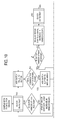
- Figure 10 illustrates a flow diagram of the glitch window sweep algorithm that is carried out for each injection event type of an injection cycle.
- the routine includes the following steps:
- An initial window position A1 is set for the pre-injection and, if a glitch is detected, the glitch position is input to a data buffer.
- the window position is moved through a window step to position B1 (as shown in Figure 9 ) and, if a glitch is detected, that position is stored in the data buffer.
- position B1 as shown in Figure 9
- this is taken as an indication that a genuine valve stop event has been detected and these three glitch detection times are transferred to the first three elements of a median data array.
- This sequence of events continues for the pre-injection events of consecutive injection cycles (third, fourth, fifth injection cycles...), incrementing the window position by the window step for each cycle.
- the sequence of events is continued until such time as the glitch window has moved to a maximum window position or until the median array has become full. If the maximum window position has been reached, this signifies that the sweep has completed but without the required number of consecutive glitch events having been detected (referred to as "a result").
- a valid glitch timing point is determined as the median of the values in the median array.
- the value of the maximum window position can be set in software to any convenient value, although for speed of operation (iterations of the sweep process) it is best to keep this value to the minimum required.
- this window position may then be used to adjust the main waveform parameters.
- a given valve may perform at any opening speed and the main control waveform for the valve may be adjusted such that the corresponding physical event occurs at the required time. Since changing the main control waveform constitutes a change in operating conditions, the sweep process may also need to be re-iterated. In practice it may be useful to have programmatic damping on the number and size of adjustments to the main waveform to avoid unnecessary iteration of the sweep process.
- the glitch window position is adapted based on preceding glitch detection events, the key feature being that feedback from the glitch detection process is needed to determine the next window position.
- the detection of three consecutive glitch detection events may be taken as an indication that a genuine valve stop event has been detected, but subsequent glitch detection events may be added to the median data buffer before the median value calculation is carried out.
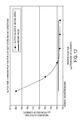
- Figures 11 and 12 show the result of the median glitch position calculation for a series of six glitch events for transient and steady state engine operating conditions, respectively.
- a more accurate selection of glitch window position is selected which has the least impact the glitch detect measurement.
- This feature is particularly useful for dealing with a wide range of operating conditions (both static and transient) which need not be known beforehand, as well as coping with a variety of valve configurations including pressure driven valves operating at high speeds (i.e. valves for which the basic timing parameters are affected by operating conditions).
- the first embodiment of the present invention relates to an adaptive window that may be used to detect glitch events in the operation of an electromagnetically controlled valve.
- One method of analysis for determining the location of a glitch event is to record and plot the position (in time) of the current maximum.
- the location of a glitch event is determined by looking for "bunching" in the position of the current maximum, for example as the window is moved between successive positions (in different engine operating cycles) the temporal location of the current maximum is expected to change by a known amount. As the glitch event is approached the maximum will move relatively less (compared to readings taken before the sampling window reached the glitch point) and so the measured current maximum positions will get closer to one another. The presence of the glitch event can then be inferred.
- the above analysis technique is potentially susceptible to mis-detection of the glitch event due to noise and other anomalies in the measured current profile.
- the signal processing required to implement the above technique may also place significant processing loading on the processor used to manipulate the sampled data.
- the second embodiment of the present invention therefore provides an analysis implementation that reduces calculation overhead and reduces the need for signal processing.
- the second embodiment of the present invention takes the sampled raw current data and calculates the first and second derivatives of the current values with respect to time.
- the reason behind going to the second differential is that looking for a maximum by examination of the raw data alone leads to mis-detection, as every sample will have a maximum and using a threshold above which the maximum is defined means that samples close to the glitch points would still falsely trigger.
- the second differential method ensures that the sample has passed through a genuine maximum.
- the third differential of the current values may be determined and analysed to determine where the third differential crosses zero. This further differential is used to avoid false detection caused by brief spikes or noise over the threshold limits.
- differentials in the detection routine gives a good detection response over a range of possible valve current signatures.
- Using differentials of the form outlined below also has the advantage of adding some filtering to the raw data and in this way increases the tolerance of the algorithm to sources of outside electrical noise as would be expected in the application environment.
- This method of differential implementation also has the benefit of faster calculation because it is based on the mathematical difference between values which is numerically one of the fastest operations that can be performed by a CPU. This reduces the calculation overhead and eliminates the need for further signal processing.
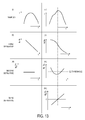
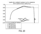
- Figure 13 shows (from top to bottom): graph (i) - the sampled current data for the current profile without a glitch event; graph (ii) - the first derivative of the current profile; graph - (iii) the second derivative of the current profile.
- Figure 13 shows (from top to bottom): graph (iv) - the sampled current data for the current profile with a glitch event; graph (v) - the first derivative of the current profile; graph (vi) - the second derivative of the current profile; graph (vii) - the third derivative of the current profile.
- the third derivative of the current profile may be calculated to confirm the location of the glitch (see graph (vii)), the glitch being located at the zero crossing point of the third derivative.
- the rules and criteria for successful detection according to the second embodiment of the present invention are designed to be simple and robust on the basis of the values of the differential arrays.
- the second differential must be greater than a given threshold (the d2 threshold) and the third differential (d3) must cross zero in the same range of points that are above the d2 threshold.
- d2 threshold a given threshold
- d3 the third differential
- d3 zero crossing method means that even in areas of high d2 values (i.e. over the d2 threshold) only actual maxima will be detected.
- This benefit of the d3 system means that the broadest possible range of values is tested for possible glitch characteristics. It also means that relatively low values of d2 threshold can be used which ensures the largest range of different valve responses can be analyzed at the same settings (i.e. it maximizes the variation that can be handled between units).
- first bounce the initial impact of the valve upon its stop
- second bounce after the first bounce, the valve motion returns to its original course and again impacts the stop but with reduced force and speed
- other bounce events The ability to detect the various bounce events has benefits for development and analysis in the motion of the valve can be studied in a more detailed way.
- a second major benefit to being able to collect bounce data is using this as an alternative to first bounce glitch for timing control purposes. For example if the valve hitting its stop is rapid enough then there can be insufficient time for the corresponding fluid event to occur (such as pressurization due to restricted flow around the valve seat).
- the second bounce may be a better predictor for the physical event as the valve is moving slower as it approaches its stop.
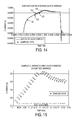
- Figure 15 shows the sampled data points 122 only with the magnitude of the current sample marked for each data point. Each data point has also been numbered as 1 through 25.
- the parameter of differential spacing may be used to control the amount of filtering or 'smoothing' that is imposed on the data.
- ds is defined as the number of spaces between sampled points which is used in the differential process.
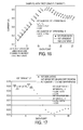
- Figure 16 shows the data samples of Figure 15 with a differential spacing of 5.
- the measure of gradient reduces to y ds + n - y n .
- the derivative calculation becomes a difference of 2 numbers extracted from an array for the y and the x component becomes a constant. In this way both the calculation complexity and the memory requirements for differential generation are reduced.
- the method is particularly well suited to embedded hardware applications which may not have access to or need floating point capabilities. Instead of looking at the difference between successive data points, the difference between data points that may be several units in time spaced from one another (i.e. non-consecutive) are examined, and it is this feature that introduces a processing benefit.
- the derivative calculation for the first two data points in Figure 16 is shown on the Figure.
- the derivative calculation can be carried out for all the data points shown in Figure 16 and the results plotted on a further graph (see Figure 17 ).
- Figure 17 shows a graph of the first derivative values calculated from the sampled current values of Figure 16 .
- the derivative calculation described above can be repeated for the data points of Figure 17 .
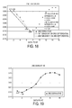
- the second derivative calculation for the first two data points in Figure 17 is shown once again on the figure and it is noted that the calculation can be carried out for all the first derivative data points in Figure 13 to produce a further graph - Figure 18 - which represents the second derivative with respect to time.
- the derivative calculation can be repeated once again on the data points of Figure 19 in order to derive the third differential of the current profile. This calculation is once again shown for the first two data points on Figure 18 and the third differential graph that results from this further calculation is shown in Figure 19 .
- the presence of a glitch event can be determined from Figure 14 by the presence of a minimum in the second differential.
- the position of this minimum provides the position of the glitch event in the injection cycle and this position may be confirmed by analysing the third differential graph of Figure 19 for the zero crossing point.
- Figures 14 to 20 are a visual illustration of the analysis process according to the second embodiment of the present invention using data extracted from the typical waveform given in Figure 14 .
- Real units of time and current are shown as an aid only.
- this data may be uncalibrated, having no units and be represented as integer values stored in memory.
- the data representations are non-unit delimited.
- the integer values may be passed directly from the sampling routine which minimizes the data handling and manipulation requirements.
- the glitch event that is detected corresponds to a discrete timing point (i.e. the sharp/discontinuous change to, or of, end of valve movement). Therefore, once the glitch event has been detected, the detector may output a valve movement signal to, for example, the vehicle's ECU that comprises this discrete timing point.
Landscapes
- Engineering & Computer Science (AREA)
- Chemical & Material Sciences (AREA)
- Combustion & Propulsion (AREA)
- Mechanical Engineering (AREA)
- General Engineering & Computer Science (AREA)
- Electrical Control Of Air Or Fuel Supplied To Internal-Combustion Engine (AREA)
- Fuel-Injection Apparatus (AREA)
- Combined Controls Of Internal Combustion Engines (AREA)
Abstract
Description
- The present invention relates to a glitch detector and method of detecting glitch events. More particularly, the present invention relates to the detection of valve movement of a valve in a fuel injector of an engine system by the detection and analysis of discontinuities ("glitches") in the current through a control actuator of the valve.
- In electronically-controlled fuel injection systems, actuator controlled valves (e.g. solenoid valves) are used to control the flow of fuel within the injector, and hence, timing, pressure and quantity of fuel injected into the engine cylinders.
- For single-valve injection systems, such as Electronic Unit Injectors (EUIs) and Electronic Unit Pumps (EUPs) a single solenoid valve - known as the "Spill Valve" - is used to control the point at which fuel pressure within the injector volume begins to increase. If the valve is open, fuel will be allowed to "spill" to low pressure (the fuel tank). Alternatively, if the valve is closed, the mass of fuel within the injector will undergo pressurisation due to the advancing cam-driven plunger reducing the injector volume. Injection of fuel into the engine's cylinder occurs once the fuel pressure within the injector becomes greater than the spring pressure which holds the injector needle closed against its seat, resulting in "injector needle lift". Fuel injection will continue until the Spill Valve re-opens, spilling fuel to low pressure, resulting in the spring forcing the injector needle to return to its closed position. In this situation, the fuel pressure necessary to lift the needle at the start of injection (known as Nozzle Opening Pressure, or NOP) is related to the force within the needle spring (i.e. spring NOP).
- In the case of twin-valve injection systems, a secondary solenoid valve is used to regulate the control pressure applied to the back of the injector needle and, hence, NOP can exceed the needle spring pressure (i.e. variable NOP). This solenoid valve is known as the "Needle Control Valve". It is a "three-way" valve, in that it exposes the port, the pressure of which is to be controlled, to either a high control pressure (when de-energised) or a drain pressure (when energised).
- Similar actuator controlled valves are used in common rail fuel injection systems too.
- This invention refers to the control of both single and twin valve injection systems.
- Valve movement is facilitated by means of an actuator which comprises an electromagnetic stator (a series of coil windings wound around a stator core), through which a current is passed to activate an armature. A valve pin is directly attached to the armature, and subsequent movement of the armature/valve assembly is used to control flow of fuel within the injector. The valve pin is held in the open position by a return spring, therefore any electromagnetic force induced by the solenoid coil is working against the spring to close the valve.
- The control of the solenoid valve is divided into two general categories, a so called "pull-in" phase and a "hold phase".
- During the pull-in phase, the armature of the solenoid-controlled valve is caused to close by the application of a first current level through the solenoid coil. During the hold phase a second, lower current level is supplied to the solenoid coil to keep the valve closed.
- The driving current provided during the pull-in phase is supplied by a capacitor. The capacitor and associated circuitry provide a further voltage supply means (in addition to the battery) and are hereinafter collectively referred to as the "boost circuit".
- The driving current provided during the hold phase is supplied by applying the standard battery voltage across the solenoid coil in order to provide the second current level. A so-called "chopping circuit" controls the application of the battery voltage so that the required drive current supplied to the actuator throughout the injection is between defined upper and lower hold thresholds.
- As the battery voltage decreases, the chopping circuit may constantly apply the battery voltage to the solenoid coil during the entire hold phase of injection in order to maintain the driving current to the solenoid between the desired threshold levels.
- In order to maintain precise fuelling using fuel injection engines it is required that either the performance of an individual injector is known or the tolerance band of a group of injectors is well known within tight limits. As a consequence this means that factory limits during production must be tight and engine testing must be sensitive enough to pick up the performance of the injector(s).
- However, no matter how good the initial set up, there will be a drift in performance over the life of the injector as components bed in or wear out. In order to address the problem of component performance drift the FIE has to have internal control systems to compensate and such control systems need to be able to detect changes in injector performance.
- For electromagnetically controlled valves as described above, the control system may detect changes in valve performance through the detection of changes in the current profile of the coil used to drive valve motion.
- The current seen on a coil has a characteristic profile due to the induction effect of a decaying magnetic field and a valve moving through that field affects the current profile (this effect is generally termed back EMF). In particular, when the valve reaches the end of its travel, it will stop moving or bounce off of its seat/stop and this change can be detected as a discontinuity, or "glitch", in the current profile.
- Since the change in current profile corresponds to the valve meeting its stop and the valve at this point in its actuated state, it follows that what is being detected correlates with the physical events triggered by the actuated valve. Therefore, the change in the characteristic profile of the current provides an effective way to measure the start of injection or pressure rise without reference to external sensors.
- A glitch detection system that is able to reliably and efficiently detect the changes in the current profile can then relate the change in the current profile to physical events such as the start/end of pressure and start/end of injection (delivery). This gives initial performance benefits as well as allowing the system to self correct if there are changes in valve response. It follows that one of the main disadvantages of the system without glitch is that there is no way to control the injector timing to compensate for any changes that occur over the life of the system. It is known that the injector components can undergo two significant changes after installation, namely the bedding in period and wear caused during normal operation. These two conditions mean that the injector performance deviates from the factory set values over its service lifetime.
- There is currently no method to track changes in the valve movement characteristics in situ. Presently the only way to compare the valve performance is by removal from the application and testing in a controlled environment with reference to initial factory data (a 'before and after' type test).
- Existing glitch detection relies on sampling either the voltage or current through the coil during a sampling window and then examining the measurements to determine when the valve has stopped moving. This method of glitch detection has a number of shortcomings and performance limitations. One of these limitations is that the glitch/sampling window actually adds energy to the system (since a voltage is artificially applied which in turn drives additional current into the system) and as such is influencing the system performance. More specifically, the extra energy can extend the time the valve is actuated by adding enough energy to effectively re-actuate the valve or lead to erratic valve timing where the force/energy balance is close to sensitive limits.
- Glitch windows may also have the problem that the window position has an influence on the position of the current discontinuity that is recorded. The closer the glitch event ("the discontinuity") is to the end of the glitch window, the more energy has entered the coil windings and as such this will tend to retard the natural progress of the valve (partial re-energisation). This means the greater the window length before the glitch event, the greater the magnitude of the imposed error.
- As a result of the effects of window position, any detection routine must be able to rapidly and efficiently evaluate the available data and make a glitch decision in the shortest possible time. This means that the detection criteria must be mathematically as simple as possible and be paired with a sufficiently powerful CPU to reduce the negative impacts of having the glitch window in the wrong position. Ideally, a decision on the glitch status should be decided on a shot to shot basis for the best performance benefits.
- Due to the operating environment in which the injectors run, there is always a degree of electrical noise (typically high frequency RF) present in the engine system. Appropriate sampling methods and hardware acquisition can reduce this noise to a minimum but a successful glitch strategy must also incorporate some form of noise filtering or rejection. Existing methods for glitch detection which include digital signal processing are either too slow (mathematically intensive) to avoid the error due to window position or they are insufficiently effective at eliminating noise induced errors.
- Since the glitch window is a deviation from the natural current decay by forced voltage application, there will always be a measured (i.e. non zero) current associated with it. A key difficulty in prior art glitch detection systems is discriminating between a valid glitch event and a non valid event. In other words, the detection routine must be able to distinguish the difference between a natural current decay profile and a profile with the effects of a change in motion by the armature.
- The difference between these two profiles can be subtle and traditionally has been difficult to determine mathematically for the wide range of different possible valve motions. This is further complicated by the range of possible coil response profiles that all give slightly different current decay shapes.
- It is therefore an object of the present invention to provide a glitch detector and an associated method of detecting valve movements that substantially overcomes or mitigates the above mentioned problems.
- According to a first aspect of the invention, there is provided a glitch detector for detecting valve movement of a valve in a fuel injector of an engine system, the valve comprising an electromagnetic actuator which is arranged to move the valve between first and second valve positions during a valve cycle and the engine system comprising sensing means for sensing a current through the actuator. The detector comprises control means arranged to control the sensing means; inputs for receiving from the sensing means data related to the current through the actuator; a processor arranged to analyse the received data for current discontinuities; outputs for outputting a valve movement signal (e.g. glitch detect signal) in dependence upon the current discontinuities determined by the processor. The control means is arranged to enable the sensing means during a finite sampling window and is further arranged (i) to move the sampling window from a first window position for a first injection event to a progressively later window position for one or more subsequent injection events, (ii) to calculate a new sampling window position on the basis of a valve movement signal output for at least two of the preceding window positions, and (iii) to feedback the new sampling window position for a subsequent injection event.
- The present invention provides a glitch detector in which the current through the actuator of a valve in an engine is received from a sensing means and then analysed for discontinuities in the current profile which indicates the presence of a glitch event. In order to reduce the effects of the glitch/sampling window adding energy to the system a control means is arranged to enable the sensing means only during a finite sampling window. Once a current discontinuity has been identified the detector can output a glitch detect signal, which may be a timing signal indicating the end of valve movement. If the detector is able to compare the discrete timing signal to known/expected valve operation then the detector may be able to determine unexpected valve operation. In such instances the detector may output an error signal that the vehicle's engine control unit (ECU) records or an error signal for display on the dashboard of the vehicle. If the detector is linked to or part of a valve control system then the output signal may be a control signal for adapting the firing characteristics of the injector.
- Subsequent injection events are preferably either (i) successive injection events or (ii) one of pilot, main or post injection events within successive injection cycles.
- In a preferred embodiment, the new sampling window position is calculated as a median position of at least two of the preceding window positions for which a glitch detect signal is output. It may be preferable to calculate the new sampling window position as a median position of three of the preceding window positions.
- The processor is arranged to analyse the current through the actuator during the sampling window and to look for and identify discontinuities in the current flow. Such discontinuities can be linked to, for example, the valve reaching its stop and so the processor is effectively able to determine valve movements in dependence upon measured current discontinuities.
- It is noted that the sensing means may not directly sense the current through the actuator and may instead sense a parameter that is related to the current through the actuator. For example, the drive circuit may comprise a resistor in series with the actuator and the sensing means may measure the voltage across the resistor.
- Preferably, in order to reduce processing requirements, the sensing means is arranged to sample the current parameter at a plurality of sample points during the sampling window.
- Conveniently, the sensing means may measure the current through a sensing resistor. Alternatively, the sensing means may be arranged to sense the current through the actuator.
- Conveniently, the sensing means may comprise a sensing resistor and the data received at the inputs may be related to the current through the sensing resistor or the voltage across the sensing resistor.
- The valve cycle may comprise a pull-in region during which a first voltage potential is applied across the actuator so that the valve is caused to move from a first state to a second state and a hold region during which a second voltage potential or series of pulses at a second voltage potential is applied across the actuator.
- Conveniently, in such a "pull-in"/"hold" arrangement, the control means may be arranged to enable the sensing means between the pull-in and hold regions of the valve cycle. The control means may also be arranged to enable the sensing means after the hold region of the valve cycle. It is noted that these two enablement positions correspond to the points within the valve cycle when the valves within the engine are expected to reach one of their two operating positions.
- In order to allow the detection of glitch events, the control means may conveniently be arranged to output a control signal to one or more control switches in order to isolate the actuator from a power supply and to open a current path comprising the actuator and the current sensing means. It is noted that at the back end of the valve cycle, i.e. after the hold phase, the current through the actuator will fall towards zero. In order to detect the movement of the valve the control means may open a current path that is inactive during the pull-in and hold phases such that a current (which includes the effects from the back EMF in the system) flows through the sensing means/drive circuit.
- Conveniently, the control means may be arranged to progressively move the sampling window away from the end of the hold region in successive injection events.
- Effective glitch detection must include as small as possible a processing overhead for noise control. Using a method that relies solely on maxima detection in the current profile is ineffective since every sample will have a maximum that may or may not correspond to a valid glitch event. Using a threshold on the maxima is similarly ineffective since this does not allow for the range of possible valve/coil response patterns.
- Therefore, in order to identify current discontinuities in the current profile, the detector (processor within the detector) may be arranged to analyse the received data by determining the second derivative of the current through the actuator with respect to time. Conveniently, the processor may be arranged to determine the presence of a current discontinuity if a maxima or minima is detected in the second derivative of the current through the actuator.
- The second derivative may be calculated based on a differential process for which input data points are non-consecutive. This provides a processing advantage because a mathematical implementation based on a differential implementation is numerically one of the fastest operations that can be performed by a CPU.
- Preferably, the received data are input to an analysis routine of the processor in the form of integer values having no units, thereby to minimise data handling and manipulation requirements.
- Alternatively, the processor may be arranged to determine the presence of a current discontinuity if the second derivative of the current through the actuator exceeds a threshold value. This enables the detector to "filter out" transient effects within the current profile. Preferably, the second derivative of the current through the actuator should also exceed the threshold value for a set period of time in order for the detector to determine the presence of a current discontinuity. This also helps filter out transient spikes in the profile.
- Conveniently, the processor may be arranged to determine the location of the current discontinuity by determining the third derivative of the current, I, with respect to time, the location of the discontinuity being equal to the time when d3I/dt3 = 0.
- According to a second aspect of the present invention, there is provided a method of detecting valve movement of a valve in a fuel injector of an engine system, the valve comprising an electromagnetic actuator which is arranged to move the valve between first and second positions during a valve cycle, the method comprising sampling the current through the actuator during a finite sampling window, analyzing the sampled current for current discontinuities, and determining valve movements in dependence upon the current discontinuities. The method further comprises moving the sampling window from a first window position for a first injection event to a progressively later window position for one or more subsequent injection events, calculating a new sampling window position on the basis of a valve movement signal (e.g. glitch detect signal) output for at least two of the preceding window positions, and feeding back the new sampling window position for a subsequent injection event.
- According to a third aspect of the present invention, there is provided a glitch detector for detecting valve movement of a valve in a fuel injector of an engine system, the valve comprising an electromagnetic actuator which is arranged to move the valve between first and second positions during a valve cycle. The detector comprises inputs for receiving data related to the current through the actuator; a processor arranged to analyse the received data for current discontinuities by determining the second derivative with respect to time of the current through the actuator; and outputs for outputting a valve movement signal (e.g. glitch detect signal) in dependence upon the current discontinuities determined by the processor. The processor may be further arranged to calculate the second derivative based on a differential process for which input data points are non-consecutive.
- According to a fourth aspect of the present invention, there is provided a method of detecting valve movement of a valve in a fuel injector of an engine system, the valve comprising an electromagnetic actuator which is arranged to move the valve between first and second positions during a valve cycle, the method comprising: sampling the current through the actuator in order to determine current data; analyzing the sampled current data for current discontinuities and outputting a valve movement signal in dependence upon the current discontinuities. The current data is analysed by determining the second derivative with respect to time of the current through the actuator. The second derivative may be calculated based on a differential process for which input data points are non-consecutive.
- This process of differentiation provides a substantially more efficient method than the prior art, in terms of processing and memory resources.
- The method may be further improved by using non-unit delimited input data in the differential process.
- The present invention extends to a carrier medium for carrying a computer readable code for controlling a controller or engine control unit to carry out the method of the second or fourth aspects of the invention and to an engine control unit for a vehicle comprising a detector according to the first or third aspects of the invention.
- It is noted that preferred features of the first aspect of the present invention may apply to the second, third and fourth aspects of the invention also.
- Another aspect of the invention provides a glitch detector for detecting valve movement of a valve in a fuel injector of an engine system, the valve comprising an electromagnetic actuator which is arranged to move the valve between first and second positions during an engine operating cycle, the engine system comprising sensing means for sensing a current through the actuator, the detector comprising: control means arranged to control the sensing means; inputs for receiving from the sensing means data related to the current through the actuator; a processor arranged to analyse the received data for current discontinuities and outputs for outputting a valve movement signal in dependence upon the current discontinuities determined by the processor wherein the control means is arranged to enable the sensing means during a finite sampling window and is arranged to move the sampling window from a first position in the engine operating cycle to a second position in the engine operating cycle.
- In order that the invention may be more readily understood, reference will now be made, by way of example, to the accompanying drawings in which:
-
Figure 1 is a sketch comparing glitch and non-glitch current waveforms; -
Figure 2 is a simple circuit schematic of a drive circuit for an electromagnetically controlled valve actuator; -
Figure 3a shows a typical current profile through an actuator during a single combustion cycle; -
Figure 3b shows the valve movement of the actuator corresponding to the current profile ofFigure 3a ; -
Figure 3c shows a sampling window between the pull-in and hold phases of a current profile; -
Figure 4 is a graph showing current/valve movement with time along with a sampling window; -
Figure 5 shows a sampling window in various positions relative to the end of the hold phase; -
Figures 6 to 8 are further graphs similar toFigure 4 depicting the sampling window in progressively later positions; -
Figure 9 shows three injection cycles, each comprising a pilot (pre), main and post injection event, to illustrate how the method of the invention is applied to injection cycles comprising more than one injection event; -
Figure 10 is a flow diagram to illustrate the method steps of an embodiment of the invention; -
Figure 11 is a graph to illustrate the negative effects of glitch window position on glitch detect time for steady state engine conditions; -
Figure 12 is a graph to illustrate the negative effects of glitch window position on glitch detect time for transient engine conditions; -
Figure 13 shows various current and current derivative graphs for a case where there is a glitch event and a case where there is no glitch event; -
Figures 14 to 20 show various current and current derivative traces with respect to time. -
Figure 1 is a simple representative sketch showing a voltage waveform V that is applied across an actuator and two current profiles I1 and I2. The first current profile I1 shows the current that flows through the actuator coils as a result of back EMF when there are no sudden changes in the motion of the valve. It can be seen that the current profile is smooth. - By contrast, in the second current profile I2 there is a discontinuity. This corresponds to a sudden change in the motion of the valve, e.g. when it reaches its stop. The present invention is concerned with the identification of these types of glitch in the current through the actuator and with the minimisation of the problems associated with known glitch detection methods.
-
Figure 2 is a representation of asimple drive circuit 2 for a coil-basedactuator 4, i.e. an electromagnetically controlled coil and aglitch detector 6 in accordance with an embodiment of the present invention. - The circuit comprises a power supply 8 (in this
case 50V), asolenoid actuator 4 and a sensing means 10 which comprises asensing resistor 12. Two controllable switches (switch 14 and switch 16) connect thepower supply 8 to thesensing resistor 12 andactuator 4.Cross circuit connections diode - The
glitch detector 6 comprisesinputs 26 for receiving data related to the current through theactuator 4, processing means 28, control means 30 for controllingswitches - The voltage across the sensing resistor can be measured and therefore the current through the solenoid determined. The power supply and
controllable switches Figure 2 ). - A typical
current profile 40 representing the current through theactuator 4 during a single combustion cycle is shown inFigure 3a. Figure 3b shows thecorresponding valve movement 42 as the current varies. - The operation of the valve and drive circuit will now be described with reference to
Figures 2 and3 . - In order to initiate injection, both switches, 14 and 16, are closed. The current through the
actuator 4 then rises from zero up to amaximum peak value 44. This phase of the injection cycle is referred to as the "pull-in" phase (or alternatively as the "front end"). - Once the current has reached its maximum value, switch 14 is opened and the current begins to decay naturally. During this current decay the valve moves such that injection commences. As the current falls to a certain level,
switch 14 is repeatedly opened and closed (or "chopped") in order to maintain injection through the activated valve. This chopping is shown by a number of smaller peak values 46, 48, 50 in the current profile. This phase of the injection cycle is known as the "hold" phase. - To terminate injection both
switches - In order to detect when the valve reaches its stop, switch 16 may be re-opened such that a current path is formed. Due to the effects of the valve moving through the magnetic field created by the actuator coil, a back EMF is set up that either re-enforces the current or partially cancels the current (depending on the direction of motion of the valve). This period of EMF-related current and normal current superposition is shown in
Figure 3a (between 52 and 54).Figure 3b shows the corresponding valve lift during the current events. When the valve reaches its stop there will be a discontinuity orglitch 56 in the current profile which corresponds to feature 58 inFigure 3a/3b . (It is noted that the valve depicted inFigure 3b undergoes a "bounce"event 59. This type of event can occur in cases of rapid valve timing changes where the valve may effectively bounce). - This "glitch detection" phase of
Figures 3a and 3b is also known as the "back end" of the combustion cycle/engine operating cycle of the engine. - It is also noted that there will be a further "glitch event" 60 that is produced as the valve first reaches its activated state (i.e. between the pull-in and hold phases).
- In any given combustion cycle there will be two
glitch events Figure 3a has been marked to show the location of twosampling windows - It is also noted that to reduce processor loading further the current through the actuator would normally be sampled at a number of defined sample points rather than continuously through the sampling window. This is illustrated in
Figure 3c in which thesampling window 62 between the pull-in and hold phases is shown in more detail and individual sampling points 66 are highlighted. -
Figure 4 shows the effect the glitch window may potentially have on the movement of the valve. It is noted thatFigure 4 shows asample window 80 that is too early relative to the movement of the valve. - The current profile at the end of the hold phase is shown in more detail in
Figure 4 . A sampling window is also shown during which a current (which includes the effects from the back EMF in the system) flows through the drive circuit. Thecurrent profile 70 during the sampling window has a characteristic shape. - The movement of the valve as the current varies is also shown in the Figure. A first
valve lift line 72 is shown which indicates that the valve should reach its stop position shortly after the end of the sampling window. A secondvalve movement trace 74 depicting the actual valve movement is also shown. Thissecond trace 74 illustrates the effects of the current in reenergising the drive circuit of the valve. It can be seen that the sampling window has the effect of delaying the valve. - To reliably detect a glitch event in such circumstances is difficult. A prior art solution is to extend the duration of the sampling window (i.e. in this "back end" example of
Figure 4 this would be activated by keepingswitch 2 closed for longer). This solution however would have the effect of delaying the valve movement even further since keepingswitch 2 open for longer means that the current input and hence magnetic field strength affecting the valve would be greater, retarding its natural motion. - A sampling window and method of glitch detection in accordance with a first embodiment of the present invention is shown in
Figure 5 . In this embodiment of the invention the sampling window is not fixed at a certain point in the combustion cycle of the engine but is instead capable of being swept in time between different cycles. - In
Figure 5 , five different sampling window locations are depicted relating to a specific injection event (e.g. pre-injection, main injection or post injection) within subsequent injection cycles. It is also noted that the five sampling window locations are arranged to be progressively moved away from the end of the hold region in successive injection cycles. This is done in order to ensure that the first glitch event is detected and to mitigate against the possibility of a secondary glitch event (caused by valve bounce as described) above being misclassified as the primary glitch event. - The
window 80 starts in an initial position (Position 1), which may be a fixed period of time after the end of the hold period. In this position thecurrent profile 82 resembles the profile ofFigure 4 in which the current slowly builds to a maximum at the end of the sampling window before falling away to zero. From thevalve movement trace 84 shown inFigure 5 it can be seen that the sampling window's initial position is too early and has missed the "glitch point" 86 (i.e. the valve stop). - In the next injection cycle the
sampling window 80 has been advanced to a later time (Position 2). Theprofile 88 has now changed and the maximum 90 in the current profile is now seen to be located part way through the sampling window 80 (as opposed to at the end of the sampling window as in the first position). It is clear that the sampling window has "found" theglitch 86. - In
Position 3, for the next injection cycle, thesampling window 80 has been moved even further forward in time. Thecurrent profile 92 is similar to that ofPosition 2 but thecurrent discontinuity 94 now appears in a slightly earlier part of the current profile. - In Positions 4 and 5, for subsequent injection cycles, the
sampling window 80 has been moved past thefirst glitch event 86. Thecurrent profile 96 inPosition 4 shows no evidence of a current discontinuity but thecurrent profile 98 inPosition 5 shows afurther discontinuity 100 which represents a secondary valve stop event 102 (it is noted that in cases of rapid valve timing changes the valve may effectively bounce and so there will be a secondary glitch event). - A few observations relating to the above discussion of the first embodiment of the invention are noted. Firstly, in
Positions glitch event 86 is actually a constant time after the end of the hold period. It is only the sampling window 80 (and thereforecurrent profile 88, 92) that has moved to a later time betweenPositions - The glitch event that is detected corresponds to a discrete timing point (i.e. the sharp/discontinuous end of valve movement). Therefore, once the glitch event has been detected, the detector may output a valve movement signal to, for example, the vehicle's ECU that comprises this discrete timing point.
-
Figure 5 describes the use of anadaptive sampling window 80 at the back end of the injection cycle. It is however noted that the same principle may be applied to a sampling window at the front end of the injection cycle. An example of such a sampling window is depicted inFigure 3c and is discussed in more detail below. It is noted that in this case thesampling window 80/sample points 66 may be moved in time until the front end glitch event is detected. - Further advantages of the adaptive sampling window according to the present embodiment of the invention are as follows:
- An adaptive window sweep allows detection of the glitch event when the individual valve characteristics are unknown. This means that the individual valve timings required for accurate and precise adjustment of waveforms can be found while the injector is running, instead of relying on factory testing. It also means that rapid valve timing changes (for example if the valve seat is damaged by debris) can be picked up and compensated for.
- The effect of energy input to the system can be minimized by moving the sampling/glitch window as far as possible from sensitive areas. For example, if the sampling window is too close to the end of the hold region, the valve may not open and the valve actuation period may be extended. Similarly, if the sampling window is too far from the end of the hold region, there is a risk of unwanted detection of secondary bounces or other artefacts.
- As the window moves past the glitch event, less energy will be returned to the magnetic flux and hence there will be a smaller imposed error due to window position.
- A moving sampling window means that the glitch event can be searched for by a series of steps from the sampling window initial position (Position 1) to the sampling window end position (Position 5). Typically the start position is offset from the end of the hold region.
- The moving sampling window allows for detection of the glitch under transient conditions without changing the major search parameters.
- The sampling window position is adapted to the different positions required for detection due to changed engine running conditions (e.g. speed/load changes).
Figure 5 gives an example of a back end sampling window sampled from a typical running condition. The minimum and maximum window positions are also adapted according to the current running conditions. This means that the effective search area can be maximized for each condition as well as avoid any problem areas. - Where the glitch position can be estimated (or is known) from a previous detection at a given condition, the adaptive window is able to jump directly to this location and begin fine tuning the position as below.
- After finding a glitch, the adaptive window is able to centre itself on the glitch position and fine tune the detection by small movements around the known glitch point. This allows for higher precision as the glitch value can then be an amalgam of several real time values.
- As described in relation to a further embodiment of the invention below, a suitable processing algorithm may be used to identify the presence of a glitch. Advantageously, by moving the
sampling window 80 at the front end of the injection cycle allows the same algorithm to be used for both types of detection since ultimately the algorithm will only see a limited number of samples. This improves both the memory usage and data handling requirements. The following further benefits are also noted with respect to a front end sampling window: - The fact that a moving sampling window is used means that a reduced number of samples are required which in turn reduces CPU and memory load for the sampling algorithm at both the front end and the back end.
- Using adaptive front end sampling means that there is better response to transient or rapidly changing engine conditions.
- Adaptive front end sampling also reduces the possibility of noise or spikes triggering a false detection since at any time only a fraction of the total current profile is being examined.
- The adaptive front end sampling window moves the region of sampled points in the current data away from the point of peak current in the same manner that the glitch window is moved away from its minimum position. The delay between the peak current in the pull-in phase and the start of sampled region is increased in an analogous way to moving the window position for the back end. A key difference is that the start of the chop region is linked to the end of the sampling window by a set delay. This means that the start of the chop region relative to the sampling window is fixed but moves away from the peak position at the same time the sampling window is moved up until the maximum sampling position is reached. Thus if a glitch is detected, the start of the chop region will occur at a set time after the glitch in order to minimize the energy loss of the coil by reducing the time when the magnetic field is in the free decay state.
-
Figures 6 to 8 show further, more detailed examples of anadaptive sampling window 80 in accordance with the first embodiment of the present invention and are considered in conjunction withFigure 4 described above. -
Figure 4 represents the initial position of the adaptive sampling window. As shown inFigure 4 the window extends from approximately 0.25 milliseconds from the end of the hold phase to 0.75 milliseconds after the end of the hold phase. - In
Figure 6 the start of thesampling window 80 has moved to approximately 0.3 milliseconds after the end of the hold phase. The end of the sampling window is now located at approximately 0.8 milliseconds. For comparison thelocation 108 of the maximum current fromFigure 4 is marked onFigure 6 and it can clearly be seen that the maximum position has moved relative toFigure 4 . - Valve movement (both
normal motion 72 and window affected valve motion 74) is again marked onFigure 6 and it can be seen that thewindow 80 ends just as the valve would (if the sampling window were not affecting valve motion) be approaching its stop position. However, because of the re-energising effect of the window drive circuit the valve movement is again delayed. - In
Figure 7 thesampling window 80 has again moved position and it now extends from approximately 0.4 milliseconds to 0.9 milliseconds after the end of the hold phase. - In this Figure it can be seen that both of the valve movement traces reach zero within the confines of the sampling window thereby indicating that the sampling window is now overlapping the stop position of the valve. The current
maximum positions Figures 4 and6 are marked onFigure 7 . - The current profile now shows a discontinuity (glitch) 112 at around 0.8 milliseconds after the end of the hold phase.
- In
Figure 8 the current maximum 114 is now clearly located within the window. For comparison the maximum fromFigure 4 is indicated on the current profile. - The above description of the first embodiment of the invention relates to "sweeping" the glitch window for successive injections within an engine operating cycle (e.g. speed/load condition). In practice, and as shown in
Figure 9 , an injection cycle may include more than one injection event, in which case a glitch window "sweep" takes place for each of the like-injection events over consecutive injection cycles. - Referring to
Figure 9 , an example injection cycle includes a pilot injection (or pre-injection), a main injection and a post injection. The current profile for three injection cycles is shown, together with the position of the moving glitch window for each event. Forinjection cycle 1, the pre-injection has a glitch window position A1, the main injection has a glitch window position A2 and the post injection has a glitch window position A3. Likewise, forinjection cycle 2 the pre-injection has a glitch window position B1, the main injection has a glitch window position B2 and the post injection has a glitch window position B3 and forinjection cycle 3 the pre-injection has a glitch window position C1, the main injection has a glitch window position C2 and the post injection has a glitch window position C3. A single valve cycle (i.e. where the valve moves from an initial position to an activated position and then returns to its initial position), corresponding to the pre-injection event ofinjection cycle 1, is indicated by the box X. -
Figure 10 illustrates a flow diagram of the glitch window sweep algorithm that is carried out for each injection event type of an injection cycle. The routine includes the following steps: - An initial window position A1 is set for the pre-injection and, if a glitch is detected, the glitch position is input to a data buffer.
- For the next pre-injection event, the window position is moved through a window step to position B1 (as shown in
Figure 9 ) and, if a glitch is detected, that position is stored in the data buffer. When three consecutive glitch detection events have been detected, this is taken as an indication that a genuine valve stop event has been detected and these three glitch detection times are transferred to the first three elements of a median data array. - This sequence of events continues for the pre-injection events of consecutive injection cycles (third, fourth, fifth injection cycles...), incrementing the window position by the window step for each cycle. The sequence of events is continued until such time as the glitch window has moved to a maximum window position or until the median array has become full. If the maximum window position has been reached, this signifies that the sweep has completed but without the required number of consecutive glitch events having been detected (referred to as "a result"). When the median array becomes full, a valid glitch timing point is determined as the median of the values in the median array.
- Where the sweep of window position completes without a result, the value of the maximum window position can be set in software to any convenient value, although for speed of operation (iterations of the sweep process) it is best to keep this value to the minimum required.
- Where a valid glitch window position is determined from the median of the values in the median array, this window position may then be used to adjust the main waveform parameters. Thus, a given valve may perform at any opening speed and the main control waveform for the valve may be adjusted such that the corresponding physical event occurs at the required time. Since changing the main control waveform constitutes a change in operating conditions, the sweep process may also need to be re-iterated. In practice it may be useful to have programmatic damping on the number and size of adjustments to the main waveform to avoid unnecessary iteration of the sweep process.
- With the window in this optimum position for subsequent injection events the impact of the window position on the glitch time is minimised and the accuracy of any further glitch times are maximised. If the glitch stops being detected at this centred position (for example if engine operating conditions change), the sweep process is restarted. The centred window position value may be stored in memory and used as the starting point for any subsequent sweep iterations to speed up the detection process. In this way the glitch window position is adapted based on preceding glitch detection events, the key feature being that feedback from the glitch detection process is needed to determine the next window position.
- The same method steps are also followed for the main- and post-injection events of the injection cycles, with the glitch positions for each being stored in a designated data buffer for that particular injection event type. A median value of glitch position is calculated once the median array is full and this value is used for subsequent injection events of that type.
- In practice it may be preferable to use more than three glitch detection events to calculate the median value. For example, the detection of three consecutive glitch detection events may be taken as an indication that a genuine valve stop event has been detected, but subsequent glitch detection events may be added to the median data buffer before the median value calculation is carried out.
- It can be seen from
Figure 11 andFigure 12 that the greatest influence of window position on detected glitch time occurs for the first few detections, so it is beneficial to add as many further detection events as possible to the median array. In this way the median value calculated will have the least bias due to early window positions. A drawback to having a large median array size is the potential to sweep past the glitch position before filling the median array. In this way the choice of median array size becomes a compromise between accuracy and robustness for any given application. For example, it may be preferable for the median value to be calculated from three consecutive glitch events and a further three glitch events (not necessarily consecutive) within the sweep (i.e. before the maximum window position is reached). By way of example,Figures 11 and12 show the result of the median glitch position calculation for a series of six glitch events for transient and steady state engine operating conditions, respectively. By continually adapting the glitch window position based on several preceding glitch detection events (e.g. by calculating the median value), a more accurate selection of glitch window position is selected which has the least impact the glitch detect measurement. This feature is particularly useful for dealing with a wide range of operating conditions (both static and transient) which need not be known beforehand, as well as coping with a variety of valve configurations including pressure driven valves operating at high speeds (i.e. valves for which the basic timing parameters are affected by operating conditions). - The first embodiment of the present invention relates to an adaptive window that may be used to detect glitch events in the operation of an electromagnetically controlled valve.
- In the second embodiment of the present invention an analysis technique for determining the presence of a discontinuity in the sampled current profile is disclosed.
- It can be seen from
Figures 4 ,6-8 that the position of the maximum in the current profile moves with thesampling window 80 until aglitch event 112 is uncovered at which point the current maximum remains fixed. - One method of analysis for determining the location of a glitch event is to record and plot the position (in time) of the current maximum. The location of a glitch event is determined by looking for "bunching" in the position of the current maximum, for example as the window is moved between successive positions (in different engine operating cycles) the temporal location of the current maximum is expected to change by a known amount. As the glitch event is approached the maximum will move relatively less (compared to readings taken before the sampling window reached the glitch point) and so the measured current maximum positions will get closer to one another. The presence of the glitch event can then be inferred.
- The above analysis technique is potentially susceptible to mis-detection of the glitch event due to noise and other anomalies in the measured current profile. The signal processing required to implement the above technique may also place significant processing loading on the processor used to manipulate the sampled data.
- The second embodiment of the present invention therefore provides an analysis implementation that reduces calculation overhead and reduces the need for signal processing.
- The second embodiment of the present invention takes the sampled raw current data and calculates the first and second derivatives of the current values with respect to time. The reason behind going to the second differential is that looking for a maximum by examination of the raw data alone leads to mis-detection, as every sample will have a maximum and using a threshold above which the maximum is defined means that samples close to the glitch points would still falsely trigger. The second differential method ensures that the sample has passed through a genuine maximum.
- In one aspect of this embodiment of the present invention the third differential of the current values may be determined and analysed to determine where the third differential crosses zero. This further differential is used to avoid false detection caused by brief spikes or noise over the threshold limits.
- The method of using differentials in the detection routine gives a good detection response over a range of possible valve current signatures. Using differentials of the form outlined below also has the advantage of adding some filtering to the raw data and in this way increases the tolerance of the algorithm to sources of outside electrical noise as would be expected in the application environment. This method of differential implementation also has the benefit of faster calculation because it is based on the mathematical difference between values which is numerically one of the fastest operations that can be performed by a CPU. This reduces the calculation overhead and eliminates the need for further signal processing.
- The second embodiment of the present invention will be described in detail with reference to
Figures 14 to 20 . InFigure 13 , however, a comparison of the analysis technique according to the second embodiment of the present invention is illustrated with respect to (i)-(iii) an idealised current profile (no glitch event) and (iv)-(vii) an idealised current profile exhibiting a glitch event. - The left hand side of
Figure 13 shows (from top to bottom): graph (i) - the sampled current data for the current profile without a glitch event; graph (ii) - the first derivative of the current profile; graph - (iii) the second derivative of the current profile. - The right hand side of
Figure 13 shows (from top to bottom): graph (iv) - the sampled current data for the current profile with a glitch event; graph (v) - the first derivative of the current profile; graph (vi) - the second derivative of the current profile; graph (vii) - the third derivative of the current profile. - In graph (i) it can be seen that the current profile is a smooth curve. The derivative of this current profile is shown in graph (ii) and is seen to be a straight line of negative gradient. The second derivative of the current profile is therefore a straight line.
- By contrast, it can be seen that the current profile in graph (iv) has a discontinuity at the marked location. The first derivative of the current profile is shown in graph (v) and due to the discontinuity it is noted that the first derivative is not a straight line as was the case in graph (ii).
- In graph (vi) the second derivative of the current profile has been taken for the glitch event current profile and it can be seen that there is a minimum in the trace (and the minimum is centred on the position of the glitch). The presence of the glitch can therefore be conveniently be determined by calculating the second derivative and analysing the second derivative for regions which exceed a threshold value. It is noted that the position of the minimum (or maximum in the case of a glitch analysis performed on the front end of the injection cycle) equates to the location of the glitch.
- The third derivative of the current profile may be calculated to confirm the location of the glitch (see graph (vii)), the glitch being located at the zero crossing point of the third derivative.
- The rules and criteria for successful detection according to the second embodiment of the present invention are designed to be simple and robust on the basis of the values of the differential arrays. The second differential must be greater than a given threshold (the d2 threshold) and the third differential (d3) must cross zero in the same range of points that are above the d2 threshold. There is an added feature that there must be a minimum number of points to be a valid range for detection of the d3 zero crossing to avoid false triggering due to spikes/noise.
- Using the d3 zero crossing method means that even in areas of high d2 values (i.e. over the d2 threshold) only actual maxima will be detected. This benefit of the d3 system means that the broadest possible range of values is tested for possible glitch characteristics. It also means that relatively low values of d2 threshold can be used which ensures the largest range of different valve responses can be analyzed at the same settings (i.e. it maximizes the variation that can be handled between units).
- Using the above method of detection also has the benefit of being able to discriminate between different valve motion events. Since the window moves linearly and the d2 threshold can be changed easily, the control of these parameters allows detection of first bounce (the initial impact of the valve upon its stop), second bounce (after the first bounce, the valve motion returns to its original course and again impacts the stop but with reduced force and speed) and other bounce events. The ability to detect the various bounce events has benefits for development and analysis in the motion of the valve can be studied in a more detailed way. A second major benefit to being able to collect bounce data is using this as an alternative to first bounce glitch for timing control purposes. For example if the valve hitting its stop is rapid enough then there can be insufficient time for the corresponding fluid event to occur (such as pressurization due to restricted flow around the valve seat).
- In this instance, the second bounce may be a better predictor for the physical event as the valve is moving slower as it approaches its stop.
- The method of differential calculation is described below in conjunction with
Figures 14 to 20 . - In
Figure 14 , acurrent profile 120 is shown. During the sampling window the current is sampled m times at equal time intervals, x (in this example m = 25), as indicated bysample points 122. -
Figure 15 shows the sampleddata points 122 only with the magnitude of the current sample marked for each data point. Each data point has also been numbered as 1 through 25. - The parameter of differential spacing (ds) may be used to control the amount of filtering or 'smoothing' that is imposed on the data. ds is defined as the number of spaces between sampled points which is used in the differential process.
Figure 16 shows the data samples ofFigure 15 with a differential spacing of 5. - As the gradient between any two points on the current sample is equivalent to the differential at a point halfway between the two, taking the gradient between points spaced ds apart gives the slope at a point halfway between the two. It follows that ds is therefore limited between ds = 1 (consecutive points, no filtering) and


form 
- The method is particularly well suited to embedded hardware applications which may not have access to or need floating point capabilities. Instead of looking at the difference between successive data points, the difference between data points that may be several units in time spaced from one another (i.e. non-consecutive) are examined, and it is this feature that introduces a processing benefit.
- The derivative calculation for the first two data points in
Figure 16 is shown on the Figure. The derivative calculation can be carried out for all the data points shown inFigure 16 and the results plotted on a further graph (seeFigure 17 ). - As noted above
Figure 17 shows a graph of the first derivative values calculated from the sampled current values ofFigure 16 . In order to obtain the second derivative of the sampled current the derivative calculation described above can be repeated for the data points ofFigure 17 . The second derivative calculation for the first two data points inFigure 17 is shown once again on the figure and it is noted that the calculation can be carried out for all the first derivative data points inFigure 13 to produce a further graph -Figure 18 - which represents the second derivative with respect to time. - The derivative calculation can be repeated once again on the data points of
Figure 19 in order to derive the third differential of the current profile. This calculation is once again shown for the first two data points onFigure 18 and the third differential graph that results from this further calculation is shown inFigure 19 . -
Figure 20 is a combined graph showing the current sampled during the glitch window and the first, second and third derivatives (i.e. a combination ofFigures 14 to 19 ). It is noted that the form of the derivative calculation described above will reduce the number of data points at each successive iteration of the process because the calculation relies on taking the difference between two data points and therefore the last five data points will, in the above example where ds = 5, not have a corresponding data point to calculate a difference value from. - It is noted that the presence of a glitch event can be determined from
Figure 14 by the presence of a minimum in the second differential. The position of this minimum provides the position of the glitch event in the injection cycle and this position may be confirmed by analysing the third differential graph ofFigure 19 for the zero crossing point. -
Figures 14 to 20 are a visual illustration of the analysis process according to the second embodiment of the present invention using data extracted from the typical waveform given inFigure 14 . Real units of time and current are shown as an aid only. In practice this data may be uncalibrated, having no units and be represented as integer values stored in memory. In other words, the data representations are non-unit delimited. The integer values may be passed directly from the sampling routine which minimizes the data handling and manipulation requirements. - As also noted above, the glitch event that is detected corresponds to a discrete timing point (i.e. the sharp/discontinuous change to, or of, end of valve movement). Therefore, once the glitch event has been detected, the detector may output a valve movement signal to, for example, the vehicle's ECU that comprises this discrete timing point.
- It will be understood that the embodiments described above are given by way of example only and are not intended to limit the invention, the scope of which is defined in the appended claims. It will also be understood that the embodiments described may be used individually or in combination.
Claims (15)
- A glitch detector (6) for detecting valve movement of a valve in a fuel injector of an engine system, the valve comprising an electromagnetic actuator (4) arranged to move the valve between first and second valve positions during a valve cycle, the engine system comprising sensing means (10) for sensing a current through the actuator, the detector comprising:control means (30) arranged to control the sensing means;inputs for receiving from the sensing means data related to the current through the actuator (4);a processor (28) arranged to analyse the received data for current discontinuities; andoutputs for outputting a valve movement signal in dependence upon the current discontinuities determined by the processor;wherein the control means is arranged to enable the sensing means during a finite sampling window (80);
and characterised in that the control means is further arranged;(i) to move the sampling window from a first window position for a first injection event to a progressively later window position for one or more subsequent injection events;(ii) to calculate a new sampling window position on the basis of a valve movement signal output for at least two of the preceding window positions; and(iii) to feedback the new sampling window position for a subsequent injection event. - A detector as claimed in Claim 1, wherein subsequent injection events are either (i) successive injection events or (ii) one of pilot (A1, B1, C1), main (A2, B2, C2) or post (A3, B3, C3) injection events within successive injection cycles.
- A detector as claimed in Claim 1 or Claim 2, wherein the new sampling window position is calculated as a median position of at least two of the preceding window positions for which a valve movement signal is output.
- A detector as claimed in any of Claims 1 to 3, wherein the sensing means (10) is arranged to sample the current at a plurality of sample points during the sampling window.
- A detector as claimed in any of Claims 1 to 4, wherein the valve cycle comprises a pull-in region during which a first voltage potential is applied across the actuator so that the valve is caused to move from a first state to a second state and a hold region during which a second voltage potential or series of pulses at a second voltage potential is applied across the actuator.
- A detector as claimed in Claim 5, wherein the control means (30) is arranged to enable the sensing means (10) either (i) between the pull-in and hold regions of the valve cycle or (ii) after the hold region of the valve cycle.
- A detector as claimed in Claim 5 or Claim 6, wherein the control means (30) is arranged to progressively move the sampling window away from the end of the hold region in successive injection cycles.
- A detector as claimed in any of Claims 1 to 7, wherein the processor (28) is arranged to analyse the received data by determining the second derivative of the current through the actuator (4) with respect to time.
- A detector as claimed in Claim 8, wherein the processor (28) is arranged to determine the presence of a current discontinuity if a maxima or minima is detected in the second derivative of the current through the actuator.
- A detector as claimed in either Claim 8 or Claim 9, wherein the processor(28) is arranged to determine the presence of a current discontinuity if the second derivative of the current through the actuator exceeds a threshold value.
- A detector as claimed in any of Claims 8 to 10, wherein the processor (28) is arranged to determine the location of the current discontinuity by determining the third derivative of the current, I, with respect to time, the location of the discontinuity being equal to the time when d3I/dt3 = 0.
- A method of detecting valve movement of a valve in a fuel injector of an engine system, the valve comprising an electromagnetic actuator (4) which is arranged to move the valve between first and second positions during a valve cycle, the method comprising:sampling the current through the actuator (4) during a finite sampling window,analyzing the sampled current for current discontinuities, anddetermining valve movements in dependence upon the current discontinuities,characterised in that the sampling window (80) is moved from a first window position for a first injection event to a progressively later window position for one or more subsequent injection events, and in that the method further comprises calculating a new sampling window position on the basis of a valve movement signal output for at least two of the preceding window positions; and feeding back the new sampling window position for a subsequent injection event.
- A glitch detector for detecting valve movement of a valve in a fuel injector of an engine system, the valve comprising an electromagnetic actuator (4) which is arranged to move the valve between first and second positions during a valve cycle, the detector comprising:inputs for receiving data related to the current through the actuator (4);a processor (28) arranged to analyse the received data for current discontinuities by determining the second derivative with respect to time of the current through the actuator; andoutputs for outputting a valve movement signal in dependence upon the current discontinuities determined by the processor;characterised in that the processor is further arranged to calculate the second derivative based on a differential process for which input data points are non-consecutive.
- A method of detecting valve movement of a valve in a fuel injector of an engine system, the valve comprising an electromagnetic actuator (4) which is arranged to move the valve between first and second positions during a valve cycle, the method comprising:sampling the current through the actuator (4) in order to determine current data;analyzing the sampled current data for current discontinuities by determining the second derivative with respect to time of the current through the actuator; andoutputting a valve movement signal in dependence upon the current discontinuities;characterised in that the method includes calculating the second derivative based on a differential process for which input data points are non-consecutive.
- A carrier medium for carrying a computer readable code for controlling a controller or engine control unit to carry out the method of Claim 12 or 14.
Priority Applications (1)
| Application Number | Priority Date | Filing Date | Title |
|---|---|---|---|
| EP08167857.5A EP2060763B1 (en) | 2007-11-15 | 2008-10-29 | Glitch Detector and Method of Detecting Glitch Events |
Applications Claiming Priority (2)
| Application Number | Priority Date | Filing Date | Title |
|---|---|---|---|
| EP07254464A EP2060762A1 (en) | 2007-11-15 | 2007-11-15 | Glitch detector and method of detecting glitch events |
| EP08167857.5A EP2060763B1 (en) | 2007-11-15 | 2008-10-29 | Glitch Detector and Method of Detecting Glitch Events |
Publications (3)
| Publication Number | Publication Date |
|---|---|
| EP2060763A2 true EP2060763A2 (en) | 2009-05-20 |
| EP2060763A3 EP2060763A3 (en) | 2015-05-20 |
| EP2060763B1 EP2060763B1 (en) | 2018-05-16 |
Family
ID=39295565
Family Applications (2)
| Application Number | Title | Priority Date | Filing Date |
|---|---|---|---|
| EP07254464A Withdrawn EP2060762A1 (en) | 2007-11-15 | 2007-11-15 | Glitch detector and method of detecting glitch events |
| EP08167857.5A Active EP2060763B1 (en) | 2007-11-15 | 2008-10-29 | Glitch Detector and Method of Detecting Glitch Events |
Family Applications Before (1)
| Application Number | Title | Priority Date | Filing Date |
|---|---|---|---|
| EP07254464A Withdrawn EP2060762A1 (en) | 2007-11-15 | 2007-11-15 | Glitch detector and method of detecting glitch events |
Country Status (3)
| Country | Link |
|---|---|
| US (1) | US7917310B2 (en) |
| EP (2) | EP2060762A1 (en) |
| JP (1) | JP2009121482A (en) |
Cited By (5)
| Publication number | Priority date | Publication date | Assignee | Title |
|---|---|---|---|---|
| WO2011151288A1 (en) * | 2010-06-02 | 2011-12-08 | Continental Automotive Gmbh | Method and device for controlling a valve |
| EP2868886A1 (en) * | 2013-10-29 | 2015-05-06 | Continental Automotive Systems US, Inc. | Method and apparatus for detecting selective catalytic reduction injector opening time |
| CN104832308A (en) * | 2013-10-29 | 2015-08-12 | 大陆汽车系统公司 | Direct injection solenoid injector opening time detection |
| GB2561549A (en) * | 2017-04-06 | 2018-10-24 | Delphi Int Operations Luxembourg Sarl | Method of detecting a doser valve opening or closing event |
| GB2564393A (en) * | 2017-07-05 | 2019-01-16 | Delphi Int Operations Luxembourg Sarl | A method of adaptively sampling data to determine the start of injection in a solenoid actuated valve |
Families Citing this family (35)
| Publication number | Priority date | Publication date | Assignee | Title |
|---|---|---|---|---|
| JP4508215B2 (en) * | 2007-05-24 | 2010-07-21 | トヨタ自動車株式会社 | Control device for internal combustion engine |
| DE102008054702A1 (en) * | 2008-12-16 | 2010-06-17 | Robert Bosch Gmbh | Method for controlling a solenoid valve of a quantity control in an internal combustion engine |
| RU2418190C2 (en) * | 2009-06-22 | 2011-05-10 | Федеральное государственное образовательное учреждение высшего профессионального образования "Челябинский государственный агроинженерный университет" | Method of diagnosing engine fuel feed system |
| JP5331663B2 (en) | 2009-11-30 | 2013-10-30 | 日立オートモティブシステムズ株式会社 | Electromagnetic fuel injection valve drive circuit |
| IT1399311B1 (en) * | 2010-04-07 | 2013-04-16 | Magneti Marelli Spa | METHOD OF DETERMINING THE CLOSING INSTANT OF AN ELECTROMAGNETIC FUEL INJECTOR |
| DE102011075521B4 (en) * | 2011-05-09 | 2013-01-31 | Continental Automotive Gmbh | Method for detecting a closing time of a valve having a coil drive and valve |
| US8813723B2 (en) * | 2011-05-20 | 2014-08-26 | GM Global Technology Operations LLC | System and method for detecting a stuck fuel injector |
| DE102011079015B4 (en) * | 2011-07-12 | 2020-03-19 | Man Energy Solutions Se | Process for machine condition monitoring |
| MX352606B (en) * | 2011-10-28 | 2017-11-29 | Deka Products Lp | Product dispensing system with pwm controlled solenoid pump. |
| RU2477384C1 (en) * | 2012-03-14 | 2013-03-10 | Федеральное государственное бюджетное образовательное учреждение высшего профессионального образования "Челябинская государственная агроинженерная академия" | Method of diagnosing engine fuel feed system electrically driven fuel pumps |
| WO2013191267A1 (en) * | 2012-06-21 | 2013-12-27 | 日立オートモティブシステムズ株式会社 | Control device for internal combustion engine |
| JP5761144B2 (en) | 2012-09-13 | 2015-08-12 | 株式会社デンソー | Fuel injection control device |
| JP5790611B2 (en) * | 2012-09-13 | 2015-10-07 | 株式会社デンソー | Fuel injection control device |
| FR3002851B1 (en) | 2013-03-07 | 2015-06-19 | Robocath | ROBOTISE CATHETERISM SYSTEM TRAINING MODULE. |
| JP6169404B2 (en) * | 2013-04-26 | 2017-07-26 | 日立オートモティブシステムズ株式会社 | Control device for solenoid valve and control device for internal combustion engine using the same |
| US20140373508A1 (en) * | 2013-06-19 | 2014-12-25 | Continental Automotive Systems, Inc. | Reductant delivery unit for automotive selective catalytic reduction with thermally optimized peak-and-hold actuation based on an injector open event |
| GB201501205D0 (en) * | 2015-01-26 | 2015-03-11 | Rolls Royce Plc | Open switch fault detection and identification in a two-level voltage source power converter |
| DE102015204686A1 (en) * | 2015-03-16 | 2016-09-22 | Robert Bosch Gmbh | Method for controlling fuel metering |
| US10012170B2 (en) | 2015-04-17 | 2018-07-03 | Continental Automotive Systems, Inc. | Method, system and apparatus for detecting injector closing time |
| CN108352242B (en) * | 2015-09-21 | 2020-11-06 | 舍弗勒技术股份两合公司 | Control unit and method for monitoring the operating state of an electromagnetic actuator |
| AU2016277616B2 (en) * | 2015-12-23 | 2021-05-27 | Schneider Electric Industries Sas | A method for detecting a fault in a recloser |
| US10444121B2 (en) * | 2016-05-03 | 2019-10-15 | Sap Se | Fault detection using event-based predictive models |
| CN106409359B (en) * | 2016-08-31 | 2018-05-01 | 中广核工程有限公司 | A kind of integrated first failure and the security function monitoring system and method for actuator supervision |
| US10401398B2 (en) | 2017-03-03 | 2019-09-03 | Woodward, Inc. | Fingerprinting of fluid injection devices |
| WO2019136489A1 (en) * | 2018-01-08 | 2019-07-11 | Broan-Nutone Llc | System and method for integrated control of supply fan |
| CN109736949B (en) * | 2018-12-20 | 2020-06-02 | 潍柴动力股份有限公司 | Detection device and detection method for fuel injection pump signal panel |
| US11230990B2 (en) | 2019-11-11 | 2022-01-25 | Caterpillar Inc. | Method and system for valve movement detection |
| KR102233163B1 (en) * | 2019-12-13 | 2021-03-29 | 주식회사 현대케피코 | Injector control method of vehicle and control apparatus thereof |
| US11268471B1 (en) | 2020-11-24 | 2022-03-08 | Caterpillar Inc. | Method and system for identification of fuel injector type |
| GB2603901B (en) * | 2021-02-15 | 2024-05-01 | Delphi Tech Ip Ltd | A method of determining closing time of needle valve of a fuel injector |
| JP7472824B2 (en) * | 2021-02-26 | 2024-04-23 | 株式会社デンソー | Fuel injection control device |
| JP2024147837A (en) * | 2021-08-23 | 2024-10-17 | 日立Astemo株式会社 | Solenoid valve control device |
| US11795886B2 (en) * | 2021-12-13 | 2023-10-24 | Caterpillar Inc. | Reduced energy waveform for energizing solenoid actuator in fuel injector valve |
| US12110832B2 (en) * | 2022-08-03 | 2024-10-08 | Caterpillar Inc. | Fuel injector control system and method |
| CN120223515B (en) * | 2025-05-26 | 2025-09-23 | 四川职业技术学院 | Remote control and fault diagnosis method and system for Internet of things equipment |
Family Cites Families (8)
| Publication number | Priority date | Publication date | Assignee | Title |
|---|---|---|---|---|
| DE3843138A1 (en) * | 1988-12-22 | 1990-06-28 | Bosch Gmbh Robert | METHOD OF CONTROLLING AND DETECTING THE MOVEMENT OF AN ARMATURE OF AN ELECTROMAGNETIC SWITCHING DEVICE |
| FR2694047B1 (en) * | 1992-07-21 | 1996-04-26 | Bosch Gmbh Robert | METHOD AND INSTALLATION FOR CONTROLLING A FUEL METERING SYSTEM CONTROLLED BY AN ELECTROMAGNETIC VALVE. |
| GB9225622D0 (en) * | 1992-12-08 | 1993-01-27 | Pi Research Ltd | Electromagnetic valves |
| DE4322199C2 (en) * | 1993-07-03 | 2003-06-18 | Bosch Gmbh Robert | Method and device for controlling an electromagnetic consumer |
| DE4420282A1 (en) * | 1994-06-10 | 1995-12-14 | Bosch Gmbh Robert | Method and device for controlling an electromagnetic consumer |
| DE19611885B4 (en) * | 1996-03-26 | 2007-04-12 | Robert Bosch Gmbh | Method and device for controlling an electromagnetic switching element |
| GB0216347D0 (en) * | 2002-07-13 | 2002-08-21 | Delphi Tech Inc | Control method |
| US7328690B2 (en) * | 2003-09-26 | 2008-02-12 | General Electric Company | Apparatus and method for accurate detection of locomotive fuel injection pump solenoid closure |
-
2007
- 2007-11-15 EP EP07254464A patent/EP2060762A1/en not_active Withdrawn
-
2008
- 2008-10-29 EP EP08167857.5A patent/EP2060763B1/en active Active
- 2008-11-12 US US12/291,672 patent/US7917310B2/en active Active
- 2008-11-14 JP JP2008292170A patent/JP2009121482A/en active Pending
Cited By (13)
| Publication number | Priority date | Publication date | Assignee | Title |
|---|---|---|---|---|
| CN103026038B (en) * | 2010-06-02 | 2015-11-25 | 大陆汽车有限公司 | For the method and apparatus of control valve |
| CN103026038A (en) * | 2010-06-02 | 2013-04-03 | 欧陆汽车有限责任公司 | Method and device for controlling a valve |
| WO2011151288A1 (en) * | 2010-06-02 | 2011-12-08 | Continental Automotive Gmbh | Method and device for controlling a valve |
| US9103458B2 (en) | 2010-06-02 | 2015-08-11 | Continental Automotive Gmbh | Method and device for controlling a valve |
| EP2884084A3 (en) * | 2013-10-29 | 2015-12-02 | Continental Automotive Systems US, Inc. | Direct injection solenoid injector opening time detection |
| CN104832308A (en) * | 2013-10-29 | 2015-08-12 | 大陆汽车系统公司 | Direct injection solenoid injector opening time detection |
| EP2868886A1 (en) * | 2013-10-29 | 2015-05-06 | Continental Automotive Systems US, Inc. | Method and apparatus for detecting selective catalytic reduction injector opening time |
| US9453488B2 (en) | 2013-10-29 | 2016-09-27 | Continental Automotive Systems, Inc. | Direct injection solenoid injector opening time detection |
| US9759116B2 (en) | 2013-10-29 | 2017-09-12 | Continental Automotive Systems, Inc. | Method and apparatus for detecting selective catalytic reduction injector opening time |
| GB2561549A (en) * | 2017-04-06 | 2018-10-24 | Delphi Int Operations Luxembourg Sarl | Method of detecting a doser valve opening or closing event |
| GB2561549B (en) * | 2017-04-06 | 2019-05-29 | Delphi Tech Ip Ltd | Method of detecting a doser valve opening or closing event |
| GB2564393A (en) * | 2017-07-05 | 2019-01-16 | Delphi Int Operations Luxembourg Sarl | A method of adaptively sampling data to determine the start of injection in a solenoid actuated valve |
| GB2564393B (en) * | 2017-07-05 | 2019-10-16 | Delphi Tech Ip Ltd | A method of adaptively sampling data to determine the start of injection in a solenoid actuated valve |
Also Published As
| Publication number | Publication date |
|---|---|
| US20090132180A1 (en) | 2009-05-21 |
| EP2060763B1 (en) | 2018-05-16 |
| EP2060763A3 (en) | 2015-05-20 |
| EP2060762A1 (en) | 2009-05-20 |
| JP2009121482A (en) | 2009-06-04 |
| US7917310B2 (en) | 2011-03-29 |
Similar Documents
| Publication | Publication Date | Title |
|---|---|---|
| EP2060763B1 (en) | Glitch Detector and Method of Detecting Glitch Events | |
| CN103518241B (en) | Improved electrical control of the actuator for determining the armature stop moment | |
| EP3417162B1 (en) | Detection of valve open time for solenoid operated fuel injectors | |
| US10712373B2 (en) | Fingerprinting of fluid injection devices | |
| US11230990B2 (en) | Method and system for valve movement detection | |
| AU2004280437B2 (en) | Apparatus and method for accurate detection of locomotive fuel injection pump solenoid closure | |
| US9903294B2 (en) | Method and device for injecting fuel into an internal combustion engine | |
| US8483933B2 (en) | Method for operating a fuel injector | |
| US9046442B2 (en) | Method and apparatus for operating an injection valve | |
| KR20130115269A (en) | Ascertaining the ballistic trajectory of an electromagnetically driven armature of a coil actuator | |
| EP1634313B1 (en) | A method of controlling the operation of a solenoid | |
| EP2514956A1 (en) | Method of controlling an electromagnetic actuator | |
| EP2455600A1 (en) | Method and apparatus for operating an injection valve | |
| EP4291766B1 (en) | A method of determining closing time of needle valve of a fuel injector | |
| JP7424240B2 (en) | injection control device | |
| JP3899660B2 (en) | Injection timing detection device |
Legal Events
| Date | Code | Title | Description |
|---|---|---|---|
| PUAI | Public reference made under article 153(3) epc to a published international application that has entered the european phase |
Free format text: ORIGINAL CODE: 0009012 |
|
| AK | Designated contracting states |
Kind code of ref document: A2 Designated state(s): AT BE BG CH CY CZ DE DK EE ES FI FR GB GR HR HU IE IS IT LI LT LU LV MC MT NL NO PL PT RO SE SI SK TR |
|
| AX | Request for extension of the european patent |
Extension state: AL BA MK RS |
|
| RAP1 | Party data changed (applicant data changed or rights of an application transferred) |
Owner name: DELPHI TECHNOLOGIES HOLDING S.A.R.L. |
|
| RAP1 | Party data changed (applicant data changed or rights of an application transferred) |
Owner name: DELPHI INTERNATIONAL OPERATIONS LUXEMBOURG S.A.R.L |
|
| RIC1 | Information provided on ipc code assigned before grant |
Ipc: F02D 41/20 20060101AFI20141218BHEP |
|
| PUAL | Search report despatched |
Free format text: ORIGINAL CODE: 0009013 |
|
| AK | Designated contracting states |
Kind code of ref document: A3 Designated state(s): AT BE BG CH CY CZ DE DK EE ES FI FR GB GR HR HU IE IS IT LI LT LU LV MC MT NL NO PL PT RO SE SI SK TR |
|
| AX | Request for extension of the european patent |
Extension state: AL BA MK RS |
|
| RIC1 | Information provided on ipc code assigned before grant |
Ipc: F02D 41/20 20060101AFI20150416BHEP |
|
| 17P | Request for examination filed |
Effective date: 20151120 |
|
| RBV | Designated contracting states (corrected) |
Designated state(s): AT BE BG CH CY CZ DE DK EE ES FI FR GB GR HR HU IE IS IT LI LT LU LV MC MT NL NO PL PT RO SE SI SK TR |
|
| AKX | Designation fees paid |
Designated state(s): AT BE BG CH CY CZ DE DK EE ES FI FR GB GR HR HU IE IS IT LI LT LU LV MC MT NL NO PL PT RO SE SI SK TR |
|
| AXX | Extension fees paid |
Extension state: AL Extension state: BA Extension state: MK Extension state: RS |
|
| 17Q | First examination report despatched |
Effective date: 20160428 |
|
| GRAP | Despatch of communication of intention to grant a patent |
Free format text: ORIGINAL CODE: EPIDOSNIGR1 |
|
| INTG | Intention to grant announced |
Effective date: 20171128 |
|
| GRAS | Grant fee paid |
Free format text: ORIGINAL CODE: EPIDOSNIGR3 |
|
| GRAA | (expected) grant |
Free format text: ORIGINAL CODE: 0009210 |
|
| AK | Designated contracting states |
Kind code of ref document: B1 Designated state(s): AT BE BG CH CY CZ DE DK EE ES FI FR GB GR HR HU IE IS IT LI LT LU LV MC MT NL NO PL PT RO SE SI SK TR |
|
| REG | Reference to a national code |
Ref country code: GB Ref legal event code: FG4D |
|
| REG | Reference to a national code |
Ref country code: CH Ref legal event code: EP |
|
| REG | Reference to a national code |
Ref country code: IE Ref legal event code: FG4D |
|
| REG | Reference to a national code |
Ref country code: DE Ref legal event code: R096 Ref document number: 602008055252 Country of ref document: DE |
|
| REG | Reference to a national code |
Ref country code: AT Ref legal event code: REF Ref document number: 999809 Country of ref document: AT Kind code of ref document: T Effective date: 20180615 |
|
| REG | Reference to a national code |
Ref country code: NL Ref legal event code: MP Effective date: 20180516 |
|
| REG | Reference to a national code |
Ref country code: LT Ref legal event code: MG4D |
|
| REG | Reference to a national code |
Ref country code: FR Ref legal event code: PLFP Year of fee payment: 11 |
|
| PG25 | Lapsed in a contracting state [announced via postgrant information from national office to epo] |
Ref country code: LT Free format text: LAPSE BECAUSE OF FAILURE TO SUBMIT A TRANSLATION OF THE DESCRIPTION OR TO PAY THE FEE WITHIN THE PRESCRIBED TIME-LIMIT Effective date: 20180516 Ref country code: FI Free format text: LAPSE BECAUSE OF FAILURE TO SUBMIT A TRANSLATION OF THE DESCRIPTION OR TO PAY THE FEE WITHIN THE PRESCRIBED TIME-LIMIT Effective date: 20180516 Ref country code: NO Free format text: LAPSE BECAUSE OF FAILURE TO SUBMIT A TRANSLATION OF THE DESCRIPTION OR TO PAY THE FEE WITHIN THE PRESCRIBED TIME-LIMIT Effective date: 20180816 Ref country code: SE Free format text: LAPSE BECAUSE OF FAILURE TO SUBMIT A TRANSLATION OF THE DESCRIPTION OR TO PAY THE FEE WITHIN THE PRESCRIBED TIME-LIMIT Effective date: 20180516 Ref country code: BG Free format text: LAPSE BECAUSE OF FAILURE TO SUBMIT A TRANSLATION OF THE DESCRIPTION OR TO PAY THE FEE WITHIN THE PRESCRIBED TIME-LIMIT Effective date: 20180816 Ref country code: ES Free format text: LAPSE BECAUSE OF FAILURE TO SUBMIT A TRANSLATION OF THE DESCRIPTION OR TO PAY THE FEE WITHIN THE PRESCRIBED TIME-LIMIT Effective date: 20180516 |
|
| PG25 | Lapsed in a contracting state [announced via postgrant information from national office to epo] |
Ref country code: NL Free format text: LAPSE BECAUSE OF FAILURE TO SUBMIT A TRANSLATION OF THE DESCRIPTION OR TO PAY THE FEE WITHIN THE PRESCRIBED TIME-LIMIT Effective date: 20180516 Ref country code: HR Free format text: LAPSE BECAUSE OF FAILURE TO SUBMIT A TRANSLATION OF THE DESCRIPTION OR TO PAY THE FEE WITHIN THE PRESCRIBED TIME-LIMIT Effective date: 20180516 Ref country code: GR Free format text: LAPSE BECAUSE OF FAILURE TO SUBMIT A TRANSLATION OF THE DESCRIPTION OR TO PAY THE FEE WITHIN THE PRESCRIBED TIME-LIMIT Effective date: 20180817 Ref country code: LV Free format text: LAPSE BECAUSE OF FAILURE TO SUBMIT A TRANSLATION OF THE DESCRIPTION OR TO PAY THE FEE WITHIN THE PRESCRIBED TIME-LIMIT Effective date: 20180516 |
|
| REG | Reference to a national code |
Ref country code: AT Ref legal event code: MK05 Ref document number: 999809 Country of ref document: AT Kind code of ref document: T Effective date: 20180516 |
|
| PG25 | Lapsed in a contracting state [announced via postgrant information from national office to epo] |
Ref country code: CZ Free format text: LAPSE BECAUSE OF FAILURE TO SUBMIT A TRANSLATION OF THE DESCRIPTION OR TO PAY THE FEE WITHIN THE PRESCRIBED TIME-LIMIT Effective date: 20180516 Ref country code: DK Free format text: LAPSE BECAUSE OF FAILURE TO SUBMIT A TRANSLATION OF THE DESCRIPTION OR TO PAY THE FEE WITHIN THE PRESCRIBED TIME-LIMIT Effective date: 20180516 Ref country code: AT Free format text: LAPSE BECAUSE OF FAILURE TO SUBMIT A TRANSLATION OF THE DESCRIPTION OR TO PAY THE FEE WITHIN THE PRESCRIBED TIME-LIMIT Effective date: 20180516 Ref country code: EE Free format text: LAPSE BECAUSE OF FAILURE TO SUBMIT A TRANSLATION OF THE DESCRIPTION OR TO PAY THE FEE WITHIN THE PRESCRIBED TIME-LIMIT Effective date: 20180516 Ref country code: SK Free format text: LAPSE BECAUSE OF FAILURE TO SUBMIT A TRANSLATION OF THE DESCRIPTION OR TO PAY THE FEE WITHIN THE PRESCRIBED TIME-LIMIT Effective date: 20180516 Ref country code: RO Free format text: LAPSE BECAUSE OF FAILURE TO SUBMIT A TRANSLATION OF THE DESCRIPTION OR TO PAY THE FEE WITHIN THE PRESCRIBED TIME-LIMIT Effective date: 20180516 Ref country code: PL Free format text: LAPSE BECAUSE OF FAILURE TO SUBMIT A TRANSLATION OF THE DESCRIPTION OR TO PAY THE FEE WITHIN THE PRESCRIBED TIME-LIMIT Effective date: 20180516 |
|
| REG | Reference to a national code |
Ref country code: DE Ref legal event code: R097 Ref document number: 602008055252 Country of ref document: DE |
|
| REG | Reference to a national code |
Ref country code: DE Ref legal event code: R081 Ref document number: 602008055252 Country of ref document: DE Owner name: DELPHI TECHNOLOGIES IP LIMITED, BB Free format text: FORMER OWNER: DELPHI INTERNATIONAL OPERATIONS LUXEMBOURG S.A R.L., BASCHARAGE, LU |
|
| PG25 | Lapsed in a contracting state [announced via postgrant information from national office to epo] |
Ref country code: IT Free format text: LAPSE BECAUSE OF FAILURE TO SUBMIT A TRANSLATION OF THE DESCRIPTION OR TO PAY THE FEE WITHIN THE PRESCRIBED TIME-LIMIT Effective date: 20180516 |
|
| REG | Reference to a national code |
Ref country code: GB Ref legal event code: 732E Free format text: REGISTERED BETWEEN 20190222 AND 20190227 |
|
| PLBE | No opposition filed within time limit |
Free format text: ORIGINAL CODE: 0009261 |
|
| STAA | Information on the status of an ep patent application or granted ep patent |
Free format text: STATUS: NO OPPOSITION FILED WITHIN TIME LIMIT |
|
| 26N | No opposition filed |
Effective date: 20190219 |
|
| PG25 | Lapsed in a contracting state [announced via postgrant information from national office to epo] |
Ref country code: SI Free format text: LAPSE BECAUSE OF FAILURE TO SUBMIT A TRANSLATION OF THE DESCRIPTION OR TO PAY THE FEE WITHIN THE PRESCRIBED TIME-LIMIT Effective date: 20180516 |
|
| REG | Reference to a national code |
Ref country code: CH Ref legal event code: PL |
|
| REG | Reference to a national code |
Ref country code: BE Ref legal event code: MM Effective date: 20181031 |
|
| PG25 | Lapsed in a contracting state [announced via postgrant information from national office to epo] |
Ref country code: LU Free format text: LAPSE BECAUSE OF NON-PAYMENT OF DUE FEES Effective date: 20181029 Ref country code: MC Free format text: LAPSE BECAUSE OF FAILURE TO SUBMIT A TRANSLATION OF THE DESCRIPTION OR TO PAY THE FEE WITHIN THE PRESCRIBED TIME-LIMIT Effective date: 20180516 |
|
| REG | Reference to a national code |
Ref country code: IE Ref legal event code: MM4A |
|
| PG25 | Lapsed in a contracting state [announced via postgrant information from national office to epo] |
Ref country code: BE Free format text: LAPSE BECAUSE OF NON-PAYMENT OF DUE FEES Effective date: 20181031 Ref country code: CH Free format text: LAPSE BECAUSE OF NON-PAYMENT OF DUE FEES Effective date: 20181031 Ref country code: LI Free format text: LAPSE BECAUSE OF NON-PAYMENT OF DUE FEES Effective date: 20181031 |
|
| PG25 | Lapsed in a contracting state [announced via postgrant information from national office to epo] |
Ref country code: IE Free format text: LAPSE BECAUSE OF NON-PAYMENT OF DUE FEES Effective date: 20181029 |
|
| PG25 | Lapsed in a contracting state [announced via postgrant information from national office to epo] |
Ref country code: MT Free format text: LAPSE BECAUSE OF NON-PAYMENT OF DUE FEES Effective date: 20181029 |
|
| PG25 | Lapsed in a contracting state [announced via postgrant information from national office to epo] |
Ref country code: TR Free format text: LAPSE BECAUSE OF FAILURE TO SUBMIT A TRANSLATION OF THE DESCRIPTION OR TO PAY THE FEE WITHIN THE PRESCRIBED TIME-LIMIT Effective date: 20180516 |
|
| PG25 | Lapsed in a contracting state [announced via postgrant information from national office to epo] |
Ref country code: PT Free format text: LAPSE BECAUSE OF FAILURE TO SUBMIT A TRANSLATION OF THE DESCRIPTION OR TO PAY THE FEE WITHIN THE PRESCRIBED TIME-LIMIT Effective date: 20180516 |
|
| PG25 | Lapsed in a contracting state [announced via postgrant information from national office to epo] |
Ref country code: CY Free format text: LAPSE BECAUSE OF FAILURE TO SUBMIT A TRANSLATION OF THE DESCRIPTION OR TO PAY THE FEE WITHIN THE PRESCRIBED TIME-LIMIT Effective date: 20180516 Ref country code: HU Free format text: LAPSE BECAUSE OF FAILURE TO SUBMIT A TRANSLATION OF THE DESCRIPTION OR TO PAY THE FEE WITHIN THE PRESCRIBED TIME-LIMIT; INVALID AB INITIO Effective date: 20081029 |
|
| PG25 | Lapsed in a contracting state [announced via postgrant information from national office to epo] |
Ref country code: IS Free format text: LAPSE BECAUSE OF FAILURE TO SUBMIT A TRANSLATION OF THE DESCRIPTION OR TO PAY THE FEE WITHIN THE PRESCRIBED TIME-LIMIT Effective date: 20180916 |
|
| PGFP | Annual fee paid to national office [announced via postgrant information from national office to epo] |
Ref country code: FR Payment date: 20201026 Year of fee payment: 13 |
|
| PG25 | Lapsed in a contracting state [announced via postgrant information from national office to epo] |
Ref country code: FR Free format text: LAPSE BECAUSE OF NON-PAYMENT OF DUE FEES Effective date: 20211031 |
|
| P01 | Opt-out of the competence of the unified patent court (upc) registered |
Effective date: 20230327 |
|
| REG | Reference to a national code |
Ref country code: DE Ref legal event code: R081 Ref document number: 602008055252 Country of ref document: DE Owner name: PHINIA DELPHI LUXEMBOURG SARL, LU Free format text: FORMER OWNER: DELPHI TECHNOLOGIES IP LIMITED, ST. MICHAEL, BB |
|
| PGFP | Annual fee paid to national office [announced via postgrant information from national office to epo] |
Ref country code: GB Payment date: 20250911 Year of fee payment: 18 |
|
| PGFP | Annual fee paid to national office [announced via postgrant information from national office to epo] |
Ref country code: DE Payment date: 20250912 Year of fee payment: 18 |