EP2060742A2 - Dichtungsanordnung mit zwei Konfigurationen für eine Rotationsanordnung - Google Patents
Dichtungsanordnung mit zwei Konfigurationen für eine Rotationsanordnung Download PDFInfo
- Publication number
- EP2060742A2 EP2060742A2 EP08253710A EP08253710A EP2060742A2 EP 2060742 A2 EP2060742 A2 EP 2060742A2 EP 08253710 A EP08253710 A EP 08253710A EP 08253710 A EP08253710 A EP 08253710A EP 2060742 A2 EP2060742 A2 EP 2060742A2
- Authority
- EP
- European Patent Office
- Prior art keywords
- seal
- assembly
- rotor shaft
- recited
- geometry
- Prior art date
- Legal status (The legal status is an assumption and is not a legal conclusion. Google has not performed a legal analysis and makes no representation as to the accuracy of the status listed.)
- Granted
Links
- 230000009977 dual effect Effects 0.000 title description 3
- 238000007789 sealing Methods 0.000 claims description 15
- 239000002184 metal Substances 0.000 claims description 2
- 238000000034 method Methods 0.000 claims description 2
- 239000007789 gas Substances 0.000 description 19
- 230000000712 assembly Effects 0.000 description 7
- 238000000429 assembly Methods 0.000 description 7
- 239000000567 combustion gas Substances 0.000 description 7
- 238000013461 design Methods 0.000 description 4
- 239000003595 mist Substances 0.000 description 4
- 125000006850 spacer group Chemical group 0.000 description 4
- 230000008901 benefit Effects 0.000 description 3
- OKTJSMMVPCPJKN-UHFFFAOYSA-N Carbon Chemical group [C] OKTJSMMVPCPJKN-UHFFFAOYSA-N 0.000 description 2
- 239000000284 extract Substances 0.000 description 2
- 239000000446 fuel Substances 0.000 description 2
- 238000004891 communication Methods 0.000 description 1
- 238000001816 cooling Methods 0.000 description 1
- 239000012530 fluid Substances 0.000 description 1
- 238000005461 lubrication Methods 0.000 description 1
- 238000012986 modification Methods 0.000 description 1
- 230000004048 modification Effects 0.000 description 1
- 230000009467 reduction Effects 0.000 description 1
- 230000008439 repair process Effects 0.000 description 1
- 230000000717 retained effect Effects 0.000 description 1
- 230000003068 static effect Effects 0.000 description 1
- 238000013519 translation Methods 0.000 description 1
Images

Classifications
-
- F—MECHANICAL ENGINEERING; LIGHTING; HEATING; WEAPONS; BLASTING
- F01—MACHINES OR ENGINES IN GENERAL; ENGINE PLANTS IN GENERAL; STEAM ENGINES
- F01D—NON-POSITIVE DISPLACEMENT MACHINES OR ENGINES, e.g. STEAM TURBINES
- F01D11/00—Preventing or minimising internal leakage of working-fluid, e.g. between stages
- F01D11/003—Preventing or minimising internal leakage of working-fluid, e.g. between stages by packing rings; Mechanical seals
-
- F—MECHANICAL ENGINEERING; LIGHTING; HEATING; WEAPONS; BLASTING
- F01—MACHINES OR ENGINES IN GENERAL; ENGINE PLANTS IN GENERAL; STEAM ENGINES
- F01D—NON-POSITIVE DISPLACEMENT MACHINES OR ENGINES, e.g. STEAM TURBINES
- F01D25/00—Component parts, details, or accessories, not provided for in, or of interest apart from, other groups
- F01D25/18—Lubricating arrangements
- F01D25/183—Sealing means
-
- F—MECHANICAL ENGINEERING; LIGHTING; HEATING; WEAPONS; BLASTING
- F02—COMBUSTION ENGINES; HOT-GAS OR COMBUSTION-PRODUCT ENGINE PLANTS
- F02C—GAS-TURBINE PLANTS; AIR INTAKES FOR JET-PROPULSION PLANTS; CONTROLLING FUEL SUPPLY IN AIR-BREATHING JET-PROPULSION PLANTS
- F02C7/00—Features, components parts, details or accessories, not provided for in, or of interest apart form groups F02C1/00 - F02C6/00; Air intakes for jet-propulsion plants
- F02C7/28—Arrangement of seals
-
- F—MECHANICAL ENGINEERING; LIGHTING; HEATING; WEAPONS; BLASTING
- F16—ENGINEERING ELEMENTS AND UNITS; GENERAL MEASURES FOR PRODUCING AND MAINTAINING EFFECTIVE FUNCTIONING OF MACHINES OR INSTALLATIONS; THERMAL INSULATION IN GENERAL
- F16J—PISTONS; CYLINDERS; SEALINGS
- F16J15/00—Sealings
- F16J15/16—Sealings between relatively-moving surfaces
- F16J15/34—Sealings between relatively-moving surfaces with slip-ring pressed against a more or less radial face on one member
- F16J15/3464—Mounting of the seal
- F16J15/348—Pre-assembled seals, e.g. cartridge seals
- F16J15/3484—Tandem seals
-
- F—MECHANICAL ENGINEERING; LIGHTING; HEATING; WEAPONS; BLASTING
- F05—INDEXING SCHEMES RELATING TO ENGINES OR PUMPS IN VARIOUS SUBCLASSES OF CLASSES F01-F04
- F05D—INDEXING SCHEME FOR ASPECTS RELATING TO NON-POSITIVE-DISPLACEMENT MACHINES OR ENGINES, GAS-TURBINES OR JET-PROPULSION PLANTS
- F05D2240/00—Components
- F05D2240/55—Seals
Definitions
- This invention generally relates to a seal assembly, and more particularly to an intershaft seal assembly for a rotational assembly.
- seal assemblies are used in rotating equipment to provide a seal between regions of high and low fluid pressure and temperature.
- seal assemblies are used to seal a rotating shaft on a pump, compressor, agitator, gas turbine, or other rotating equipment.
- Gas turbine engine type rotational assemblies typically include (in serial flow communication) a fan section, a compressor section, a combustor section, and a turbine section. During operation, air is pressurized in the compressor section and mixed with fuel in the combustor section for generating hot combustion gases. The hot combustion gases flow through the turbine section which extracts energy from the hot combustion gases.
- a rotor assembly includes a high speed shaft and a low speed shaft that power the engine components using the energy extracted from the hot combustion gases.
- mechanical seal assemblies are used to prevent hot, high pressure air from entering a bearing compartment that operates at a low pressure and temperature.
- a front bearing compartment in a multiple spool gas turbine engine is filled with an oil mist to lubricate the bearings that support the high speed rotor shaft and the low speed rotor shaft.
- the high speed rotor shaft and the low speed rotor shaft are separated by a gap filled with working medium gas.
- the working medium gas cools the rotor shaft.
- An intershaft seal assembly prevents the working medium gas from leaking into the oil compartment and prevents the oil mist from leaking out of the bearing compartment into the gap.
- the intershaft seal assembly typically includes two axially offset graphitic carbon ring mechanical face seals that seal the gap between the high speed rotor shaft and the low speed rotor shaft. Secondary seals may also be provided between the two face seals to limit leakage between the face seals.
- Modem day advanced gas turbine engine programs typically include rotor shafts that operate at different speeds and have different sealing requirements.
- the difference between the rotational speeds of a high speed rotor shaft and a low speed rotor may be relatively significant.
- the speed variations experienced by each face seal may result in unbalanced sealing between the high and low speed rotor shafts.
- known intershaft seal assemblies have not adequately provided for the different speed and sealing requirements of the rotor shafts.
- intershaft seal assemblies are typically heavy, complex and expensive to produce, repair and replace.
- a seal assembly for a rotational assembly includes a first seal, a second seal and a crossover support.
- the crossover support includes a first geometry for interacting with the first seal and a second, different geometry for interacting with the second seal.
- a rotational assembly includes a first rotor shaft, a second rotor shaft, and a seal assembly extending between the first rotor shaft and the second rotor shaft.
- the seal assembly includes a first seal adjacent the first rotor shaft and a second seal adjacent the second rotor shaft.
- the first seal includes a different configuration than the second seal.
- a method for sealing a gap between a high speed rotor shaft and a low speed rotor shaft of a rotational assembly includes positioning a first seal having a first configuration adjacent to the low speed rotor shaft, and positioning a second seal having a second configuration adjacent the high speed rotor shaft.
- the second configuration of the second seal is different from the first configuration of the first seal.
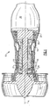
- Figure 1 illustrates selected portions of an example rotational assembly 10, such as a gas turbine engine, for example.
- the rotational assembly 10 includes a fan section 12, a low pressure compressor 14, a high pressure compressor 16, a combustor 18, a high pressure turbine 20 and a low pressure turbine 22 each disposed coaxially about an engine centerline axis A.
- air is pressurized in the compressors 14, 16 and mixed with fuel in the combustor 18 for generating hot combustion gases.
- the hot combustion gases flow through the high and low pressure turbines 20, 22, which extract energy from the hot combustion gases.
- the high pressure turbine 20 powers the high pressure compressor 16 through a high speed rotor shaft 19 and the low pressure turbine 22 powers the fan section 12 and the low pressure compressor 14 through a low speed rotor shaft 21.
- the invention is not limited to the two spool actual gas turbine architecture described and may be used with other architectures, such as a single spool actual design, a three spool actual design and other architectures.
- Core exhaust gases are discharged from the core engine through a core exhaust nozzle 32.
- An annular, non-rotatable case 24 supports the high speed rotor shaft 19 and the low speed rotor shaft 21 on a sealing arrangement 26.
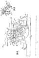
- FIG. 2 illustrates a sealing arrangement 26 of the rotational assembly 10.
- the sealing arrangement 26 includes a front bearing compartment 40.
- the bearing compartment 40 is filled with an oil mist from a suitable source to provide lubrication and cooling.
- the high speed shaft 19 and the low speed shaft 21 are spaced apart, thereby defining a gap 42.
- the gap 42 is filled with working medium gas from either one or both of the compressor sections 14, 16, which cools the high and low speed rotor shafts 19, 21.
- the working medium gas in the gap 42 is typically much warmer than the temperature inside the bearing compartment 40.
- the high speed rotor shaft 19 and the low speed rotor shaft 21 are co-axial and are co-rotating, in one example. In another example, the high speed rotor shaft 19 and the low speed rotor shaft 21 are counter-rotating.
- a seal assembly 44 minimizes leakage of the relatively high temperature working medium gas out of the gap 42 and into the bearing compartment 40. In addition, the seal assembly 44 minimizes the risk of the oil mist from leaking out of the bearing compartment 40 into the gap 42.
- the seal assembly 44 is an intershaft seal assembly for a gas turbine engine. Although the example seal assembly 44 is shown and described herein for sealing certain components of a gas turbine engine, it should be understood that other rotational assemblies would benefit from the seal assembly including, but not limited to, pumps, compressors, agitators, etc.
- the example seal assembly 44 includes a first seal 46, including for example, a metal backed face seal, the face seal extending circumferentially about the low speed rotor shaft 21 and a second seal 48 extending circumferentially about the high speed shaft 19.
- the first seal 46 and the second seal 48 are axially spaced within the bearing compartment 40.
- the first seal 46 and the second seal 48 include different configurations, as is further discussed below, and provide the necessary sealing between the gap 42 and the bearing compartment 40 of the rotational assembly 10.
- the first seal 46 includes a seal element 50, a seal seat 52, and a seal housing 54.
- the seal seat 52 rotates with the low speed shaft 21, while the seal element 50 remains static with the casing 24.
- the seal seat 52 is retained against an abutment 56 on the low speed shaft 21 by a nut assembly 58. Therefore, the seal seat 52 is carried by and rotates with the low speed shaft 21.
- the seal element 50 includes a nose 60 that contacts the seal seat 52 when the seal housing 54 is biased toward the seal seat 52 in a sealing position.
- the seal element 50 is an annular seal element, such as an annular graphitic carbon ring.
- the seal housing 54 receives the seal element 50 in an interference fit, for example, and supports the seal element 50 relative to the seal seat 52 to provide sealing therebetween.
- the seal housing 54 is in turn supported by a series of circumferentially spaced guide members 62, as is further discussed below.
- the second seal 48 includes a different configuration from the first seal 46. That is, the first seal 46 and the second seal 48 include different geometries, shapes, seal types etc. to accommodate the different speed and sealing requirements of the high speed shaft 19 and the low speed shaft 21.
- the second seal 48 includes a monoblock seal element 64, a seal seat 66 and an annular spring 68.
- a second nut assembly 59 supports the seal seat 66 against an abutment 70 of the high speed shaft 19.
- the second seal 48 is a monoblock cartridge seal, in one example. It should be understood that a person of ordinary skill in the art would recognize other suitable seal types for use within the second seal 48.
- the monoblock seal element 64 includes a nose 72 that interacts with the seal seat 66 to provide sealing between the bearing compartment 40 and the gap 42.
- the annular spring 68 biases the monoblock seal element 64 longitudinally to maintain positive contact between the monoblock seal element 64 and the seal seat 66.
- the annular spring 68 extends between wear layers 69.
- the wear layers 69 minimize wear of contacting surfaces.
- a radially outboard end 74 of the monoblock seal element 64 is secured by a series of circumferentially spaced anti-rotation lugs 23. The anti-rotation lugs 23 prevent the rotation of the monoblock seal element 64.
- Each guide member 62 includes a base section 76 and a neck section 78.
- a distal end 80 of the neck section 78 receives a retaining collar 82 to limit axial movement of the seal housing 54.
- Each of the distal end 80 and the retaining collar 82 include openings 84 to secure the retaining collar 82 on the distal end 80.
- a spacer sleeve 79 mounts on the neck section 78 of each guide member 62.
- the guide members 62 axially guide movement of the seal housing 54 along a translation direction T via engagement with the spacer sleeve 79 and flange 81 of the seal housing 54 (See Figure 3 ).
- the spacer sleeve 79 includes rounded sides 83 and flat sides 85 ( Figure 3 ).
- the flat sides 85 correspond to the flat sides of a guide slot 87 of the flange 81.
- the spacer sleeves 79 provide smooth movement of the seal housing 54 along the guide member 62, prevent rotation, and reduce friction and wear between the seal housing 54 and the neck section 78.
- the support 90 and the seal housing 54 further include a plurality of circumferentially spaced coil spring guides 86.
- the spring guides 86 receive and retain coil springs 88.
- the coil springs 88 bias the seal housing 54 longitudinally to maintain positive contact between the seal element 50 and the seal seat 52 of the first seal 46.
- the spring guides 86, the guide members 62 and the anti-rotation lugs 23 are offset circumferentially (See Figure 4 ). In one example, the spring guides 86, the guide members 62 and the anti-rotation lugs 23 are radially offset an equal distance from the engine centerline axis A. Therefore, the spring guides 86, the guide members 62 and the anti-rotation lugs 23 provide anti-rotation and guide functions for both the first seal 46 and the second seal 48.
- the example seal assembly 44 also includes a support 90.
- the support 90 includes a radial outboard end 92 and a radially inboard end 94.
- the radial outboard end 92 of the support 90 includes an outer bore 96 that is affixed to the case 24 by interference fit and a retaining ring 98.
- the radial inboard end 94 of the support 90 includes a crossover support 100.
- the crossover support 100 extends transversely from the outer bore 96.
- the crossover support 100 is radially offset from the outer bore 96.
- the crossover support 100 is radially inboard from the outer bore 96. The crossover support 100 enables the seal assembly 44 to accommodate the different configurations of the first and second seals 46, 48.
- the crossover support 100 includes a first geometry 102 that interacts with the first seal 46 and a second geometry 104 that interacts with the second seal 48.
- “Geometry” is intended to describe any arrangement of parts, objects, shapes and/or geometric figures that interact with and accommodate the different configurations of the first seal 46 and the second seal 48.
- the first geometry 102 and the second geometry 104 are different geometries.
- at least one of the first geometry 102 and the second geometry 104 include a pilot land.
- the second geometry includes a pilot land 110.
- Secondary seals 106 radially seal the seal assembly 44.
- the second geometry 104 includes a secondary seal 106.
- the seal housing 54 of the first seal 46 includes a pilot land 108 having a groove 111 for receiving a secondary seal 106.
- the second geometry 104 of the crossover support 100 also includes a groove 112 for receiving a secondary seal 106.
- the second geometry 104 is radially offset from the first geometry 102. Therefore, the crossover support 100 provides a common balance diameter 115 for both the high speed shaft 19 and the low speed shaft 21 locations of the seal assembly 44. That is, the seal assembly 44 is radially sealed at an equal distance relative to the centerline axis A. Therefore, common secondary seal hardware for both the first seal 46 and the second seal 48 is provided by the seal assembly 44.
- the secondary seals 106 include piston rings.
- the secondary seals 106 include O-ring type seals.
- the secondary seals 106 include C-ring type seals.
- the example seal assembly 44 described herein provides dual configuration seal functionality for a rotational assembly. That is, the seal assembly 44 accommodates the different speed and seal requirements of a high speed shaft 19 and a low speed shaft 21, respectively, via the crossover support 100.
- the crossover support 100 for example, includes different geometries 102, 104 that interact with seal types having different configurations.
- the seal assembly 44 provides reductions in overall seal assembly design space, cost, weight, and part quantity while providing improved wear life.
Landscapes
- Engineering & Computer Science (AREA)
- General Engineering & Computer Science (AREA)
- Mechanical Engineering (AREA)
- Chemical & Material Sciences (AREA)
- Combustion & Propulsion (AREA)
- Mechanical Sealing (AREA)
- Sealing Devices (AREA)
- Turbine Rotor Nozzle Sealing (AREA)
- Joints Allowing Movement (AREA)
- Sealing With Elastic Sealing Lips (AREA)
Applications Claiming Priority (1)
| Application Number | Priority Date | Filing Date | Title |
|---|---|---|---|
| US11/939,048 US8215894B2 (en) | 2007-11-13 | 2007-11-13 | Dual configuration seal assembly for a rotational assembly |
Publications (3)
| Publication Number | Publication Date |
|---|---|
| EP2060742A2 true EP2060742A2 (de) | 2009-05-20 |
| EP2060742A3 EP2060742A3 (de) | 2013-03-20 |
| EP2060742B1 EP2060742B1 (de) | 2019-09-25 |
Family
ID=40346251
Family Applications (1)
| Application Number | Title | Priority Date | Filing Date |
|---|---|---|---|
| EP08253710.1A Active EP2060742B1 (de) | 2007-11-13 | 2008-11-13 | Dichtungsanordnung mit zwei Konfigurationen für eine Rotationsanordnung |
Country Status (2)
| Country | Link |
|---|---|
| US (1) | US8215894B2 (de) |
| EP (1) | EP2060742B1 (de) |
Cited By (3)
| Publication number | Priority date | Publication date | Assignee | Title |
|---|---|---|---|---|
| EP2570612A1 (de) * | 2011-09-15 | 2013-03-20 | United Technologies Corporation | Turbomaschinen-Sekundärdichtungsanordnung |
| EP2787257A3 (de) * | 2013-04-05 | 2014-10-29 | Honeywell International Inc. | Flüssigkeitsübertragungsdichtungsanordnungen, Flüssigkeitsübertragungssysteme und Verfahren zur Übertragung von Prozessflüssigkeit zwischen stationären und rotierenden Komponenten damit |
| EP3401508A1 (de) * | 2017-04-06 | 2018-11-14 | United Technologies Corporation | Isolierte sitzdichtung |
Families Citing this family (9)
| Publication number | Priority date | Publication date | Assignee | Title |
|---|---|---|---|---|
| US9546560B2 (en) * | 2012-09-11 | 2017-01-17 | United Technologies Corporation | Compact double grounded mechanical carbon seal |
| WO2014107161A1 (en) | 2013-01-04 | 2014-07-10 | United Technologies Corporation | Seal assembly for arranging between a stator and a rotor |
| US10024241B2 (en) | 2013-03-15 | 2018-07-17 | United Technologies Corporation | Turbine engine face seal arrangement including anti-rotation features |
| WO2015105574A1 (en) | 2014-01-08 | 2015-07-16 | United Technologies Corporation | Flanged spring guide for a face seal arrangement |
| US9850770B2 (en) * | 2016-04-29 | 2017-12-26 | Stein Seal Company | Intershaft seal with asymmetric sealing ring |
| US10788131B2 (en) * | 2017-08-01 | 2020-09-29 | Raytheon Technologies Corporation | Face seal arrangement |
| US10655487B2 (en) * | 2018-02-15 | 2020-05-19 | Raytheon Technologies Corporation | Pressure balanced secondary seal |
| US10598046B2 (en) | 2018-07-11 | 2020-03-24 | United Technologies Corporation | Support straps and method of assembly for gas turbine engine |
| US11035253B2 (en) * | 2019-02-05 | 2021-06-15 | Raytheon Technologies Corporation | Face seal with damper |
Citations (8)
| Publication number | Priority date | Publication date | Assignee | Title |
|---|---|---|---|---|
| FR1554863A (de) | 1967-12-11 | 1969-01-24 | ||
| US4304522A (en) | 1980-01-15 | 1981-12-08 | Pratt & Whitney Aircraft Of Canada Limited | Turbine bearing support |
| US4754984A (en) | 1987-01-02 | 1988-07-05 | The United States Of America As Represented By The Secretary Of The Navy | Dual-seal-ring shaft seal |
| EP1010926A2 (de) | 1998-12-17 | 2000-06-21 | United Technologies Corporation | Zwischenwellen-Dichtungsanordnung für ein Gasturbinentriebwerk |
| EP1327802A2 (de) | 2002-01-14 | 2003-07-16 | Rolls-Royce Deutschland Ltd & Co KG | Hydraulische Dichtungsanordnung |
| EP1777376A2 (de) | 2005-10-18 | 2007-04-25 | United Technologies Corporation | Tandem-Zwischenwellen-Dichtung aus Graphit |
| EP1783329A2 (de) | 2005-11-03 | 2007-05-09 | United Technologies Corporation | Ummantelte Gleitringdichtung |
| EP2025875A2 (de) | 2007-08-17 | 2009-02-18 | United Technologies Corporation | Turbinendichtung und Sicherungsdichtung von einem Gasturbinentriebwerk und entsprechende Turbinenanordnung |
Family Cites Families (13)
| Publication number | Priority date | Publication date | Assignee | Title |
|---|---|---|---|---|
| GB969579A (en) * | 1962-11-09 | 1964-09-09 | Rolls Royce | Gas turbine engine |
| US3942804A (en) * | 1974-11-18 | 1976-03-09 | General Electric Co. | Turbomachine seal |
| US4141212A (en) * | 1977-06-20 | 1979-02-27 | Avco Corporation | Differentially geared regenerative reverse flow turbo shaft engine |
| US4159888A (en) * | 1977-10-07 | 1979-07-03 | General Motors Corporation | Thrust balancing |
| GB2092242B (en) * | 1981-01-31 | 1984-12-19 | Rolls Royce | Non-contacting gas seal |
| GB2092243B (en) * | 1981-01-31 | 1984-12-05 | Rolls Royce | Non-contacting gas seal |
| US5102295A (en) * | 1990-04-03 | 1992-04-07 | General Electric Company | Thrust force-compensating apparatus with improved hydraulic pressure-responsive balance mechanism |
| EP0685048B1 (de) * | 1992-08-11 | 2000-01-19 | United Technologies Corporation | Dichtanordnung für rotierende maschinen |
| US6132168A (en) * | 1998-12-23 | 2000-10-17 | United Technologies Corporation | Balancing a pressure drop across ring seals in gas turbine engines |
| US6619908B2 (en) * | 2001-09-10 | 2003-09-16 | Pratt & Whitney Canada Corp. | Axial and radial seal arrangement |
| US6887038B2 (en) * | 2003-09-02 | 2005-05-03 | General Electric Company | Methods and apparatus to facilitate sealing between rotating turbine shafts |
| US8608175B2 (en) * | 2005-10-28 | 2013-12-17 | United Technologies Corporation | Mechanical face seal stop pin |
| FR2907183B1 (fr) * | 2006-10-11 | 2009-01-30 | Snecma Sa | Systeme d'etancheite entre deux arbres tournants coaxiaux |
-
2007
- 2007-11-13 US US11/939,048 patent/US8215894B2/en active Active
-
2008
- 2008-11-13 EP EP08253710.1A patent/EP2060742B1/de active Active
Patent Citations (8)
| Publication number | Priority date | Publication date | Assignee | Title |
|---|---|---|---|---|
| FR1554863A (de) | 1967-12-11 | 1969-01-24 | ||
| US4304522A (en) | 1980-01-15 | 1981-12-08 | Pratt & Whitney Aircraft Of Canada Limited | Turbine bearing support |
| US4754984A (en) | 1987-01-02 | 1988-07-05 | The United States Of America As Represented By The Secretary Of The Navy | Dual-seal-ring shaft seal |
| EP1010926A2 (de) | 1998-12-17 | 2000-06-21 | United Technologies Corporation | Zwischenwellen-Dichtungsanordnung für ein Gasturbinentriebwerk |
| EP1327802A2 (de) | 2002-01-14 | 2003-07-16 | Rolls-Royce Deutschland Ltd & Co KG | Hydraulische Dichtungsanordnung |
| EP1777376A2 (de) | 2005-10-18 | 2007-04-25 | United Technologies Corporation | Tandem-Zwischenwellen-Dichtung aus Graphit |
| EP1783329A2 (de) | 2005-11-03 | 2007-05-09 | United Technologies Corporation | Ummantelte Gleitringdichtung |
| EP2025875A2 (de) | 2007-08-17 | 2009-02-18 | United Technologies Corporation | Turbinendichtung und Sicherungsdichtung von einem Gasturbinentriebwerk und entsprechende Turbinenanordnung |
Cited By (6)
| Publication number | Priority date | Publication date | Assignee | Title |
|---|---|---|---|---|
| EP2570612A1 (de) * | 2011-09-15 | 2013-03-20 | United Technologies Corporation | Turbomaschinen-Sekundärdichtungsanordnung |
| US9316119B2 (en) | 2011-09-15 | 2016-04-19 | United Technologies Corporation | Turbomachine secondary seal assembly |
| EP2787257A3 (de) * | 2013-04-05 | 2014-10-29 | Honeywell International Inc. | Flüssigkeitsübertragungsdichtungsanordnungen, Flüssigkeitsübertragungssysteme und Verfahren zur Übertragung von Prozessflüssigkeit zwischen stationären und rotierenden Komponenten damit |
| US9790863B2 (en) | 2013-04-05 | 2017-10-17 | Honeywell International Inc. | Fluid transfer seal assemblies, fluid transfer systems, and methods for transferring process fluid between stationary and rotating components using the same |
| EP3401508A1 (de) * | 2017-04-06 | 2018-11-14 | United Technologies Corporation | Isolierte sitzdichtung |
| EP3690191A1 (de) * | 2017-04-06 | 2020-08-05 | United Technologies Corporation | Isolierte sitzdichtung |
Also Published As
| Publication number | Publication date |
|---|---|
| EP2060742B1 (de) | 2019-09-25 |
| US20090121441A1 (en) | 2009-05-14 |
| US8215894B2 (en) | 2012-07-10 |
| EP2060742A3 (de) | 2013-03-20 |
Similar Documents
| Publication | Publication Date | Title |
|---|---|---|
| EP2060742B1 (de) | Dichtungsanordnung mit zwei Konfigurationen für eine Rotationsanordnung | |
| US10208611B2 (en) | Flanged spring guide for a face seal arrangement | |
| EP3232011B1 (de) | Hydrodynamischer druckverstärker mit kohlenstoffgleitringdichtung | |
| CN110005545B (zh) | 一种鼠笼弹性支承轴承腔结构 | |
| EP2977562B1 (de) | Lagergehäusedichtungssystem | |
| EP1577504A1 (de) | Lagerdichtung mit einer Sicherungsvorrichtung | |
| EP1852573A2 (de) | Dichtungsanordnung für Gasturbinen | |
| US9803493B2 (en) | Turbine bearing and seal assembly for a turbocharger | |
| EP3447251B1 (de) | Dichtungssatz für gasturbinentriebwerke | |
| US9874217B2 (en) | Turbomachine shaft sealing arrangement | |
| US9546560B2 (en) | Compact double grounded mechanical carbon seal | |
| EP3904731B1 (de) | Poröses dichtungselement mit internem fluidkanal | |
| EP3748129B1 (de) | Gleitende fluidkupplungsvorrichtung | |
| US20190226585A1 (en) | Hydrodynamic Intershaft Piston Ring Seal | |
| EP3318722B1 (de) | Dichtungsanordnung für ein drehbares bestandteil | |
| CA2630081A1 (en) | Seals, sealed systems, and methods for sealing a shaft | |
| EP3904732B1 (de) | Rotationsgerätdichtungselement mit innerem fluidkanal | |
| US11371441B2 (en) | Translating fluid delivery device | |
| CN110878760B (zh) | 用于涡轮机械的密封组件 | |
| US11933180B2 (en) | Labyrinth seal | |
| CA3202220A1 (en) | Bearing-supported shaft assembly |
Legal Events
| Date | Code | Title | Description |
|---|---|---|---|
| PUAI | Public reference made under article 153(3) epc to a published international application that has entered the european phase |
Free format text: ORIGINAL CODE: 0009012 |
|
| AK | Designated contracting states |
Kind code of ref document: A2 Designated state(s): AT BE BG CH CY CZ DE DK EE ES FI FR GB GR HR HU IE IS IT LI LT LU LV MC MT NL NO PL PT RO SE SI SK TR |
|
| AX | Request for extension of the european patent |
Extension state: AL BA MK RS |
|
| RIC1 | Information provided on ipc code assigned before grant |
Ipc: F01D 25/18 20060101ALI20121126BHEP Ipc: F01D 11/00 20060101AFI20121126BHEP Ipc: F16J 15/30 20060101ALI20121126BHEP Ipc: F02C 7/28 20060101ALI20121126BHEP |
|
| PUAL | Search report despatched |
Free format text: ORIGINAL CODE: 0009013 |
|
| AK | Designated contracting states |
Kind code of ref document: A3 Designated state(s): AT BE BG CH CY CZ DE DK EE ES FI FR GB GR HR HU IE IS IT LI LT LU LV MC MT NL NO PL PT RO SE SI SK TR |
|
| AX | Request for extension of the european patent |
Extension state: AL BA MK RS |
|
| RIC1 | Information provided on ipc code assigned before grant |
Ipc: F01D 11/00 20060101AFI20130214BHEP Ipc: F01D 25/18 20060101ALI20130214BHEP Ipc: F16J 15/30 20060101ALI20130214BHEP Ipc: F02C 7/28 20060101ALI20130214BHEP |
|
| 17P | Request for examination filed |
Effective date: 20130920 |
|
| RBV | Designated contracting states (corrected) |
Designated state(s): AT BE BG CH CY CZ DE DK EE ES FI FR GB GR HR HU IE IS IT LI LT LU LV MC MT NL NO PL PT RO SE SI SK TR |
|
| AKX | Designation fees paid |
Designated state(s): DE GB |
|
| RAP1 | Party data changed (applicant data changed or rights of an application transferred) |
Owner name: UNITED TECHNOLOGIES CORPORATION |
|
| GRAP | Despatch of communication of intention to grant a patent |
Free format text: ORIGINAL CODE: EPIDOSNIGR1 |
|
| INTG | Intention to grant announced |
Effective date: 20180621 |
|
| GRAJ | Information related to disapproval of communication of intention to grant by the applicant or resumption of examination proceedings by the epo deleted |
Free format text: ORIGINAL CODE: EPIDOSDIGR1 |
|
| GRAJ | Information related to disapproval of communication of intention to grant by the applicant or resumption of examination proceedings by the epo deleted |
Free format text: ORIGINAL CODE: EPIDOSDIGR1 |
|
| INTC | Intention to grant announced (deleted) | ||
| GRAP | Despatch of communication of intention to grant a patent |
Free format text: ORIGINAL CODE: EPIDOSNIGR1 |
|
| INTG | Intention to grant announced |
Effective date: 20190405 |
|
| GRAS | Grant fee paid |
Free format text: ORIGINAL CODE: EPIDOSNIGR3 |
|
| GRAA | (expected) grant |
Free format text: ORIGINAL CODE: 0009210 |
|
| AK | Designated contracting states |
Kind code of ref document: B1 Designated state(s): DE GB |
|
| REG | Reference to a national code |
Ref country code: GB Ref legal event code: FG4D |
|
| REG | Reference to a national code |
Ref country code: DE Ref legal event code: R096 Ref document number: 602008061272 Country of ref document: DE |
|
| REG | Reference to a national code |
Ref country code: DE Ref legal event code: R097 Ref document number: 602008061272 Country of ref document: DE |
|
| PLBE | No opposition filed within time limit |
Free format text: ORIGINAL CODE: 0009261 |
|
| STAA | Information on the status of an ep patent application or granted ep patent |
Free format text: STATUS: NO OPPOSITION FILED WITHIN TIME LIMIT |
|
| 26N | No opposition filed |
Effective date: 20200626 |
|
| REG | Reference to a national code |
Ref country code: DE Ref legal event code: R081 Ref document number: 602008061272 Country of ref document: DE Owner name: RAYTHEON TECHNOLOGIES CORPORATION (N.D.GES.D.S, US Free format text: FORMER OWNER: UNITED TECHNOLOGIES CORPORATION, FARMINGTON, CONN., US |
|
| P01 | Opt-out of the competence of the unified patent court (upc) registered |
Effective date: 20230519 |
|
| PGFP | Annual fee paid to national office [announced via postgrant information from national office to epo] |
Ref country code: GB Payment date: 20231019 Year of fee payment: 16 |
|
| PGFP | Annual fee paid to national office [announced via postgrant information from national office to epo] |
Ref country code: DE Payment date: 20231019 Year of fee payment: 16 |