EP2060733A1 - Blind, longitudinal blind, and lateral blind - Google Patents
Blind, longitudinal blind, and lateral blind Download PDFInfo
- Publication number
- EP2060733A1 EP2060733A1 EP07806849A EP07806849A EP2060733A1 EP 2060733 A1 EP2060733 A1 EP 2060733A1 EP 07806849 A EP07806849 A EP 07806849A EP 07806849 A EP07806849 A EP 07806849A EP 2060733 A1 EP2060733 A1 EP 2060733A1
- Authority
- EP
- European Patent Office
- Prior art keywords
- slat
- slats
- hanger
- gear
- shaft
- Prior art date
- Legal status (The legal status is an assumption and is not a legal conclusion. Google has not performed a legal analysis and makes no representation as to the accuracy of the status listed.)
- Granted
Links
Images


Classifications
-
- E—FIXED CONSTRUCTIONS
- E06—DOORS, WINDOWS, SHUTTERS, OR ROLLER BLINDS IN GENERAL; LADDERS
- E06B—FIXED OR MOVABLE CLOSURES FOR OPENINGS IN BUILDINGS, VEHICLES, FENCES OR LIKE ENCLOSURES IN GENERAL, e.g. DOORS, WINDOWS, BLINDS, GATES
- E06B9/00—Screening or protective devices for wall or similar openings, with or without operating or securing mechanisms; Closures of similar construction
- E06B9/24—Screens or other constructions affording protection against light, especially against sunshine; Similar screens for privacy or appearance; Slat blinds
- E06B9/26—Lamellar or like blinds, e.g. venetian blinds
- E06B9/36—Lamellar or like blinds, e.g. venetian blinds with vertical lamellae ; Supporting rails therefor
-
- E—FIXED CONSTRUCTIONS
- E06—DOORS, WINDOWS, SHUTTERS, OR ROLLER BLINDS IN GENERAL; LADDERS
- E06B—FIXED OR MOVABLE CLOSURES FOR OPENINGS IN BUILDINGS, VEHICLES, FENCES OR LIKE ENCLOSURES IN GENERAL, e.g. DOORS, WINDOWS, BLINDS, GATES
- E06B9/00—Screening or protective devices for wall or similar openings, with or without operating or securing mechanisms; Closures of similar construction
- E06B9/24—Screens or other constructions affording protection against light, especially against sunshine; Similar screens for privacy or appearance; Slat blinds
- E06B9/26—Lamellar or like blinds, e.g. venetian blinds
- E06B9/28—Lamellar or like blinds, e.g. venetian blinds with horizontal lamellae, e.g. non-liftable
- E06B9/30—Lamellar or like blinds, e.g. venetian blinds with horizontal lamellae, e.g. non-liftable liftable
- E06B9/32—Operating, guiding, or securing devices therefor
- E06B9/322—Details of operating devices, e.g. pulleys, brakes, spring drums, drives
Definitions
- the present invention relates to a blind that can adjust the angles of a plurality of slats at different speeds.
- a longitudinal blind has a hanger rail, a plurality of runners that are movable along the hanger rail, and a plurality of slats each of which is hung down from and supported by each runner.
- the slats are deployed and folded up along the hanger rail, and the angle of each slat is adjusted to adjust the amount of light that enters a room through the longitudinal blind.
- the material of the slats has a light blocking property.
- a user rotates an operation rod (operation mechanism) or pulls an operation cord to adjust the angles of the slats at the same phase. Therefore, inside of the room is fully visible to the outside depending on the angles of the slats. Even if the light blocking slats and the semitransparent slats made, for example, of lace are alternately hung down from and supported, the slats cannot be adjusted such that only the semitransparent slats are deployed along the hanger rail seen from above. Therefore, even if slats made of different materials are hung down from and supported by the hanger rail, it is difficult to obtain conspicuous effects.
- a longitudinal blind disclosed in Patent Document 1 supports a plurality of non-transparent louvers and a plurality of semitransparent louvers.
- the non-transparent louvers and the semitransparent louvers are arranged alternately one by one.
- the angle of the non-transparent louvers and the angle of the semitransparent louvers can be adjusted independently.
- the angle of only the semitransparent louvers can be adjusted such that only the semitransparent louvers extend along the hanger rail as viewed from above,
- the angle of the semitransparent louver can be adjusted to position the semitransparent louvers so as to be slanted with respect to the hanger rail.
- the angle of the non-transparent louvers can be adjusted to adjust the non-transparent louvers so as to extend vertically with respect to the hanger rail as viewed from above.
- the angle of the semitransparent louvers and the angle of the non-transparent louvers cannot be adjusted simultaneously by a single manipulation of the operation mechanism. That is, the above document discloses one embodiment in which only the angle of the non-transparent louvers can be adjusted and another embodiment in which each of the angle of the non-transparent louvers and the angle of the semitransparent louvers is adjusted independently.
- An objective of the present invention is to provide a blind in which the angles a plurality of slats can be adjusted at different speeds in an interlocking fashion,
- a blind having a frame and a plurality of slats that are rotatably supported by the frame.
- the blind further has an operation mechanism that is provided to the frame and a drive force transmission mechanism that rotates each of the slats based on the operation of the operation mechanism.
- the slats include a first slat and a second slat.
- the drive force transmission mechanism has a speed charging mechanism that rotates the first slat and the second slat at different speeds.
- a longitudinal blind having a hanger rail, a plurality of runners that are supported by the hanger rail. Each of the runners is movable along the hanger rail.
- the longitudinal blind has a hanging shaft that is rotatably supported by each runner, a plurality of slats each of which is supported by and hung down from the hanging shaft, and a tilt shaft that extends through the runners.
- the longitudinal blind further has an operation mechanism that rotates the tilt shaft, a gear mechanism that is provided to each of the runners so as to transmit rotation of the tilt shaft to each of the hanging shafts and rotate the slats, and a torque transmission mechanism that transmits torque of the gear mechanism to the hanging shaft.
- a torque value that can be transmitted by the torque transmission mechanism is a predetermined value or less.
- the slats include a first slat and a second slat. Each of the first slat and the second slat has a different material.
- the gear ratio of the gear mechanism corresponding to the first slat is set to be different from the gear ratio of the gear mechanism corresponding to the second slat.
- a lateral blind having a frame and a plurality of support mechanisms that are provided to the frame.
- the lateral blind has a plurality of slats that are supported rotatably to the frame by each of the support mechanisms, and an operation mechanism that is provided to the frame so as to adjust the angle of each slat.
- the slats include a first slat and a second slat.
- the support mechanisms include a first support mechanism that supports the first slat and a second support mechanism that supports the second slat.
- the first support mechanism and the second support mechanism each have a drive force transmission mechanism.
- the driver force transmission mechanisms rotate the first slat and the second slat at different speeds based on an operation of the operation mechanism.
- Figs. 1 to 8 show a first embodiment of the present invention.
- Figs. 1 and 2 show a longitudinal blind according to the first embodiment.
- the longitudinal blind has a hanger rail 1, a plurality of light blocking slats 2a, and a plurality of semitransparent slats 2b.
- the hanger rail 1 extending in a horizontal direction supports a plurality of runners 3 so as to be movable in a horizontal direction.
- Each of the light blocking slats 2a and the semitransparent slats 2b is hung down from one of the runners 3.
- the light blocking slats 2a and the semitransparent slats 2b are arranged alternately one by one.
- the light blocking slats 2a and the semitransparent slats 2b extend downwardly from the hanger rail 1, which is a frame.
- a material of the light blocking slat 2a which is a first slat, has a light blocking property.
- a material of the semitransparent slat 2b which is a second slat has semitransparency.
- the material of the semitransparent slat 2b is, for example, a lace material that allows a part of light to be transmitted.
- a left end cap 5a is provided at a left end (first end) of the hanger rail 1 and a right end cap 5b is provided at a right end (second end) of the hanger rail 1.
- each runner 3 supports a hanging shaft 6 so as to be rotatable.
- Each hanging shaft 6 extends in a vertical direction and supports one of the light blocking slats 2a and the semitransparent slats 2b.
- a lower end of the hanging shaft 6 has a hook 7.
- Each of the first slat hanger 14a and a second slat hanger 14b is hooked on one of the hooks 7.
- the light blocking slats 2a are hung down from the first slat hangers 14a
- the semitransparent slats 2b are hung down from the second slat hangers 14b.
- an operation cord 10 is hung down from the left end cap 5a.
- the operation cord 10 is arranged so as to go around within the hanger rail 1.
- Two ends of the operation cord 10 are attached to a lead runner 3a.
- the lead runner 3a is arranged, for example, closest to the left end cap 5a.
- the runners 3 are connected to each other by a spacer 11. Each spacer 11 determines a maximum separated distance between each pair of the runners 3.
- the runners following the lead runner 3a are pulled out in sequence.
- the operation cord 10 is pulled in an opposite direction, the lead runner 3a moves from the left end cap 5a to the right end cap 5b such that the lead runner 3a pushes back the following runners.
- the light blocking slats 2a and the semitransparent slats 2b that are hung down from and supported by the runners 3 are pulled out along the hanger rail 1 or fold up in a space under the right end cap 5b.
- the left end cap 5a supports a left end of a tilt shaft 4 rotatably and the right end cap 5b supports a right end (second end) of the tilt shaft 4 rotatably.
- the tilt shaft 4 extend through the runners 3 so as to support the runners 3.
- Three splines are formed on the tilt shaft 4.
- Each runner 3 accommodates a gear mechanism 8 that is engaged with the tilt shaft 4.
- Each gear mechanism 8 has a worm wheel 12 and a worm 13 that are engaged with each other,
- the tilt shaft 4 extends through an inner opening of the annular worm wheel 12.
- the spline of the tilt shaft 4 is engaged with a protrusion formed on an inner peripheral surface of the worm wheel 12. That is, the worm wheel 12 is integrally rotated with the tilt shaft 4.
- the worm 13 is formed in a cylindrical shape extending in a vertical direction.
- the hanging shaft 6 extends through the inner opening of the worm 13 so as to be rotatable with respect to the worm 13.
- the upper end of the hanging shaft 6 is projected upwardly from the upper end of the worm 13.
- a spring receiver 17 is provided at the upper end of the hanging shaft 6.
- the spring receiver 17 is formed in a cup-shape so as to be open downwardly.
- the spring receiver 17 accommodates the upper end of a coil spring 16.
- the hanging shaft 6 extends through the coil spring 16 and the lower end of the coil spring 16 is supported by the upper end of the worm 13 through a washer 18.
- the coil spring 16 presses the washer 18 against the worm 13 with respect to the spring receiver 17. As a result, torque of the worm 13 is transmitted to the hanging shaft 6 through the washer 18, the coil spring 16 and the spring receiver 17. That is, the coil spring 16 forms a torque transmission mechanism.
- the gear mechanism 8 forms a drive power transmission mechanism.
- the maximum value (predetermined value) of torque that can be transmitted by the torque transmission mechanism is determined by the urging force of the coil spring 16, the friction coefficient of the coil spring 16 and the washer 18, and the friction coefficient of the washer 18 and the worm 13.
- the coil spring 16 corresponding to the semitransparent slat 2b is allowed to slide with respect to the washer 18.
- the washer 18 is slidable with respect to the worm 13.
- the worm 13 corresponding to the semitransparent slat 2b can be slidable with respect to the hanging shaft 6 while transmitting the torque to the hanging shaft 6.
- the worm 13 can spin with respect to the hanging shaft 6.
- an operation rod 9 is hung down from the left end of the hanger rail 1.
- the left end cap 5a accommodates a gear mechanism (not shown) that transmits rotation of the operation rod 9 to the rotation of the tilt shaft 4. Therefore, when the operation rod 9 is rotated, the tilt shaft 4 is rotated and each hanging shaft 6 is rotated through each corresponding gear mechanism 8.
- the operation rod 9 forms an operation mechanism that operates the rotation of the light blocking slats 2a in conjunction with the rotation of the semitransparent slats 2b.
- the gear ratio of the gear mechanism 8 corresponding to the light blocking slat 2a is determined to be different from the gear ratio of the gear mechanism 8 corresponding to the semitransparent slat 2b.
- each gear ratio of the gear mechanism 8 is determined such that the rotation angle of the semitransparent slat 2b is twice the rotation angle of the light blocking slat 2a per rotation of the worm wheel 12. That is, the rotation speed of the semitransparent slats 2b is twice the rotation speed of the light blocking slats 2a.
- the gear ratio of the gear mechanism 8 is determined by adjusting a helix angle and a lead angle defined by a tooth of the worm wheel 12 and a tooth of the worm 13.
- the gear mechanism 8 forms a speed changing mechanism.
- the tilt shaft 4 when the tilt shaft 4 is rotated, the light blocking slats 2a and the semitransparent slats 2b are rotated simultaneously.
- the rotation speed of the semitransparent slats 2b is twice the rotation speed of the light blocking slats 2a.
- each first slat hanger 14a is the same as the state of each light blocking slat 2a
- the state of each second slat hanger 14b is the same as the state of each semitransparent slat 2b.
- Fig. 4 shows transition of the rotation angle of the first and second slat hangers 14a, 14b according to steps S1 to S10.
- Step S1 shows a first fully closed state of the first and second slat hangers 14a, 14b.
- Step S10 shows a second fully closed state of the first and second slat hangers 14a, 14b.
- the second slat hanger 14b In the first fully closed state, the second slat hanger 14b is positioned behind (on an upper side in Fig. 4 ) the first slat hanger 14a that is on a right side of the second slat hanger 14b.
- the second slat hanger 14b is positioned in front of (on a lower side in Fig.
- Steps 52 to S9 show states where the first and second slat hangers 14a, 14b are rotated by approximately 180 degrees from the first fully closed state to the second fully closed state.
- Step S2 shows a state where the first slat hangers 14a are rotated in the counterclockwise direction by 40 degrees from the state of step S1.
- the second slat hanger 14b is rotated in the counterclockwise direction by approximately 80 degrees from the state of step S1.
- Step S3 shows a state where the first slat hangers 14a are rotated in the counterclockwise direction by 5 degrees from the state of step S2.
- Step S4 shows a state where the first slat hangers 14a are further rotated in the counterclockwise direction by 5 degrees from the state of step S3, and step S5 shows a state where the first slat hangers 14a are further rotated in the counterclockwise direction by 5 degrees from the state of step S4.
- step S5 two ends of the second slat hanger 14b contact each of the adjacent first slat hangers 14a.
- step S5 when the first slat hangers 14a are rotated in the counterclockwise direction by 95 degrees from the first fully closed state and the second slat hanger 14b is rotated in the counterclockwise direction by 55 degrees from the first fully closed state, the first slat hangers 14a and the second slat hanger 14b contact each other. That is, in step S5, each of the two ends of the semitransparent slat 2b contacts corresponding one of the adjacent light blocking slats 2a.
- steps S5 to S9 each of the two ends of the second slat hanger 14b continuously contact corresponding one of the adjacent first slat hangers 14a. That is, in steps S5 to S9, the second slat hanger 14b is restricted by the first slat hangers 14a and continuously rotated. In other words, the rotation speed of the second slat hanger 14b in steps S5 to 9 is lower than the rotation speed or the second slat hanger 14b in steps S1 to S4.
- the first slat hangers 14a in steps S5 to S9 receive resistance force from the second slat hanger 14b and are continuously rotated. Then, as shown in step S10, the first and second, slat hangers 14a, 14b are in the second fully closed state.
- Fig. 5 shows a rotation that is opposite to that in Fig. 4 . That is, Fig. 5 shows transition of the first and second slat hangers 14a, 14b when the first and second slat hangers 14a, 14b are rotated in the clockwise direction according to steps S10 to S1 in Fig. 4 .
- the first and second slat hangers 14a, 14b in Fig. 5 are operated in the same manner as in Fig. 4 except for the rotation, direction.
- Steps S11 to S21 in Fig. 6 show a case where the gear ratio of each gear mechanism 8 is determined such that the rotation speed of the second slat hanger 14b is 1.5 times the rotation speed of the first slat hangers 14a.
- Step S11 shows the first fully closed state
- step S21 shows the second fully closed state.
- the difference between the rotation speed of the first slat hangers 14a and the rotation speed of the second slat hanger 14b is smaller compared to the case of Fig. 4 (twice).
- the second slat hanger 14b does not contact the first slat hangers 14a in steps S11 to S18.
- the second slat hanger 14b contacts the first slat hangers 14a in steps S19 to S20. That is, the first and second slat hangers 14a, 14b are continuously rotated under mutual restriction in steps S19 to S20.
- Steps S31 to S40 in Fig. 7 show a case where the gear ratio of each gear mechanism 8 is determined such that the rotation speed of the second slat hanger 14b is triple the rotation speed of the first slat hanger 14a.
- Step S31 shows the first fully closed state
- step S40 shows the second fully closed state.
- step S33 the first slat hangers 14a are rotated in the counterclockwise direction by 30 degrees from the first fully closed state and contact the second slat hanger 14b.
- steps S33 to S39 the first and second slat hangers 14a, 14b are continuously rotated under mutual restriction.
- Steps S41 to S50 in Fig. 8 show a case where the gear ratio of each gear mechanism 8 is determined such that the rotation speed of the second slat hanger 14b is four times the rotation speed of the first slat hangers 14a.
- Step S41 shows the first fully closed state
- step S50 shows the second fully closed state.
- step S42 the first slat hangers 14a are rotated in the counterclockwise direction by 20 degrees from the first fully closed state and contact the second slat hanger 14b.
- steps S42 to S49 the first and second slat hangers 14a, 14b are continuously rotated under mutual restriction.
- the first embodiment has the following advantages.
- Figs. 9(a) to 9(e) show a second embodiment of the present invention.
- Fig. 9(a) shows a first fully closed state
- Fig. 9(e) shows a second fully closed state.
- the distance between a rotation center (hanging shaft 6) of the first slat hanger 14a and a rotation center (hanging shaft 6) of the second slat hanger 14b is set to be greater than half the size of each first and second slat hanger 14a, 14b as viewed from above.
- the second slat hanger 14b is capable of rotating by 180 degrees or more.
- the size of each first and second slat hanger 14a, 14b as viewed from above is set to be smaller than the size in the first embodiment.
- the rotation speed of the second slat hanger 14b is set to be twice the rotation speed of the first slat hanger 14a.
- Alternate long and short dash lines L shown in Figs. 9(a) to 9(e) shows an extending direction of the hanger rail 1.
- the first and second slat hangers 14a, 14b are rotated in the counterclockwise direction from the first fully closed state shown in Fig. 9(a) , the first and second slat hangers 14a, 14b are moved from the state of a reversed N-shape to the state of a V-shape shown in Fig. 9(c) and moved to the state shown in Fig. 9(d) .
- the state shown in Fig. 9(d) light enters a room through the semitransparent slate 2b between the two light blocking slats 2a.
- the distance between the rotation center of the first slat hanger 14a and the rotation center of the second slat hanger 14b is greater than the state shown in Fig. 9(a) .
- first and second slat hangers 14a, 14b are moved from the state shown in Fig. 9(b) to the state shown in Fig. 9(d) , the second slat hanger 14b is rotated over the alternate long and short dash lines L without contacting the first slat hanger 14a. Accordingly, the rotation of the second slat hangers 14b is not restricted from the state shown in Fig. 9(a) to the state shown in Fig. 9(d) .
- the first slat hangers 14a shown in Fig. 9(d) are rotated by 90 degrees or more from the state shown in Fig. 9(a) and the second slat hangers 14b are rotated by 180 degrees or more from the state shown in Fig. 9(a) .
- the second slat hangers 14b contact the first slat hangers 14a and continuously rotated under restriction of the first slat hangers 14a.
- the first slat hangers 14a are rotated to be in the second fully closed state as shown in Fig. 9(e)
- the second slat hangers 14b are pushed back by the first slat hangers 14a and rotated in the counterclockwise direction to be in the second fully closed state.
- the second slat hangers 14b shown in Fig. 9(e) are parallel to the first slat hangers 14a.
- the semitransparent slats 2b made of a lace material cover a space between the light blocking slats 2a having a light blocking property and the angle of the light blocking slats 2a and the angle of the semitransparent slats 2b can be adjusted respectively.
- the semitransparent slats 2b are rotated over the state where the semitransparent slate 2b extend along the hanger rail 1, the semitransparent slats 2b are returned to be in the second fully closed state. In other words, the adjustment of the angle is completed such that the light blocking slats 2a and the semitransparent slats 2b are parallel to each other and along the hanger rail 1.
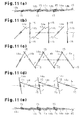
- Figs. 10 and 11 show a third embodiment of the present invention.
- the third embodiment as viewed from above, two contact pieces 15 that are projected from the two ends of the second slat hangers 14b are provided. That is, the size of the second slat hangers 14b are extended horizontally by the contact pieces 15.
- the rotation speed of the second slat hangers 14b is set to be twice the rotation speed of the first slat hangers 14a.
- the two ends of the second slat hangers 14b are outer end portions of the second slat hangers 14b with respect to the hanging shaft 6.
- the first and second slat hangers 14a, 14b are rotated in the counterclockwise direction.
- the contact pieces 15 contact the first slat hangers 14a.
- the second slat hangers 14b are rotated under restriction of the first slat hangers 14a.
- the second slat hangers 14b reliably contact the first slat hangers 14a by the contact pieces 15. Accordingly, the second slat hangers 14b are rotated in conjunction with the first slat hangers 14a.
- Figs. 12 to 21 show a fourth embodiment of the present invention.
- Fig. 12 shows a lateral blind according to the fourth embodiment.
- the lateral blind has a right side frame 21a, a left side frame 21b, a plurality of upper slats 22a and a plurality of lower slats 22b.
- the right side frame 21a and the left side frame 21b extend in an up-and-down direction and the upper slats 22a and the lower slats 22b extend in a horizontal direction.
- the right side frame 21a has a plurality of first support mechanisms 27 and a plurality of second support mechanisms 40.
- the right side frame 21a and the left side frame 21b according to the fourth embodiment form a part of a square frame that supports the two ends of the upper slats 22a and the two ends of the lower slats 22b at the rotation speed.
- the upper slats 22a which are first slats, are arranged in an upper half of the frame (upper portion) and the lower slats 22b, which are second slats, are arranged in a lower half of the frame (lower portion).
- the upper slats 22a and the lower slats 22b are formed of aluminum thin plates. A plurality of small openings are formed in the upper slats 22a. That is, light partially passes through the upper slats 22a.
- Figs. 14 and 15 show one of the first support mechanisms 27 that are arranged at the right side frame 21a.
- Each first support mechanism 27 supports the upper slat 22a rotatably with respect to the right side frame 21a,
- a plurality of first support mechanisms 27 are arranged at the left side frame 21b.
- the first support mechanisms 27 at the left side frame 21b are the same as the first support mechanisms 27 at the right side frame 21a. Therefore, the first support mechanisms 27 at the right side frame 21a will be explained.
- the right side frame 21a has a right facing piece 21c and a right outer piece 21d that is extended vertically and outwardly from the right facing piece 21c.
- the right facing piece 21c and the right outer piece 21d are formed in an L-shape.
- the left side frame 21b is formed in an L-shape having a left facing piece and a left outer piece.
- the right facing piece 21c and the left facing piece face each other.
- Each right facing piece 21c has a plurality of support openings 28.
- a slide shaft 29 is inserted through each support opening 28.
- a peripheral surface of the right facing piece 21c supports the slide shaft 29 rotatably and allows axial movement of the slide shaft 29.
- Each slide shaft 29 has a slat receiving portion 30, a flange 33, and an insertion portion 29a.
- the flange 33 is positioned between the slat receiving portion 30 and the insertion portion 29a.
- the insertion portion 29a is inserted through the support opening 28.
- the insertion portion 29a has an engagement groove 29b that extends in an axial direction.
- the slat receiving portion 30 is formed in a flat plate and an engagement projection 31 is formed at a center of the slat receiving portion 30.
- An engagement opening 32 is formed at a right end of the upper slat 22a.
- the engagement projection 31 is fitted to the engagement opening 32 such that the slide shaft 29 supports the right end of the upper slat 22a.
- the insertion portion 29a is inserted through a washer 34, a first sprocket 35, a friction washer 36, a coil spring 37 and a rotation restriction piece 38 and a clip 39 is fitted to a distal end of the insertion portion 29a.
- the clip 39 prevents the rotation restriction piece 38 from being dropped off the slide shaft 29. That is, the right facing piece 21c, the washer 34, the first sprocket 35, the friction washer 36, the coil spring 37 and the rotation restriction piece 38 are provided between the flange 33 and the clip 39 in this order.
- the friction washer 36 and the rotation restriction piece 38 have an engagement member that is engaged to the engagement groove 29b and are rotated integrally with the slide shaft 29.
- the coil spring 37 urges the friction washer 36 toward the first sprocket 35. Therefore, the rotation of the first sprocket 35 is transmitted to the friction washer 36 by a friction force caused between the surface of the first sprocket 35 and the surface of the friction washer 36. That is, the rotation of the first sprocket 35 rotates the slide shaft 29.
- the first sprocket 35 forms a part of a drive force transmission mechanism.
- the rotation restriction piece 38 is formed like a home base (pentagon) and determines a rotation area of the slide shaft 29 that is approximately 180 degrees. Any side edge of the rotation restriction piece 38 contacts the right outer piece 21d to restrict the rotation of the slide shaft 29. As a result, the rotation area of the upper slat 22a is also approximately 180 degrees. That is, the upper slat 22a is rotatable from the first fully closed state where the upper slat 22a extends in an up-and-down direction as shown in Fig. 20(a) to the second fully closed state where the upper slat 22a is reversed from the first fully closed state as shown in Fig. 20(d) .
- the lower end of the right side frame 21a rotatably supports a first drive gear 24 shown in Fig. 13
- the upper end of the right side frame 21a a rotatably supports a following gear 25.
- An endless drive belt 23 is provided over the first drive gear 24 and the following gear 25.
- the drive belt 23 is accommodated in right side frame 21a,
- the drive belt 23 has a plurality of engagement openings 26 at equal intervals so as to be engaged to the first drive gear 24 and the following gear 25.
- the lateral blind has the operation rod 9 shown in Fig. 1 or the operation mechanism (not shown in Fig. 12 ) such as the operation cord 10.
- a user operates the operation mechanism to rotate the first drive gear 24.
- the left side frame 21b accommodates the first drive gear 24, the following gear 25 and the drive belt 23, similarly.
- the operation rod 9 rotates the first drive gear 24 in the right side frame 21a and the first drive gear 24 In the left side frame 21b synchronously at the same speed.
- the drive belts 23 at the right and left sides are driven synchronously.
- the drive belt 23 is provided around the first sprocket 35. When the drive belt 23 is driven, the first sprocket 35 is rotated. This rotates the upper slats 22a.
- Figs, 16 to 18 show a second support mechanism 40.
- the second support mechanism 40 supports a lower slats 22b rotatably with respect to the right, side frame 21a.
- the second support mechanism 40 has the slide shaft 29, the friction washer 36, the coil spring 37, the rotation restriction piece 38 and the clip 39 similar to the first support mechanism 27.
- the second support mechanism 40 has a support cylinder 41 and a transmission gear 42 instead of the washer 34 and the first sprocket 35.
- the second support mechanism 40 has a gear shaft 43, a second sprocket 44 and a second drive gear 45.
- the gear shaft 43 is integrally formed with the second sprocket 44 and the second drive gear 45.
- the right facing piece 21c has a second support opening 47 in adjacent to each support opening 28.
- a peripheral surface of the right facing piece 21c rotatably supports the gear shaft 43 that is inserted through the second support opening 47.
- the drive belt 23 is meshed with the second sprocket 44.
- a slat receiving portion 30 of the slide shaft 29 supports an end portion of the lower slat 22b.
- the right facing piece 21c, the support cylinder 41, the transmission gear 42, the friction washer 36, the coil spring 37, and the rotation restriction piece 38 are arranged between the flange 33 and the clip 39 of the second support mechanism 40 in this order.
- the support cylinder 41 has a cylinder portion 41a and a flange 41b that is formed at an end portion of the cylinder portion 41a.
- the flange 41b contacts the right facing piece 21c.
- the transmission gear 42 is arranged between the cylinder portion 41a and the friction washer 36.
- the second drive gear 45 is meshed with the transmission gear 42.
- the transmission gear 42 is rotatable with respect to the slide shaft 29.
- the coil spring 37 urges the friction washer 36 against the transmission gear 42.
- a surface of the transmission gear 42 is frictionally engaged with a surface of the friction washer 36.
- the ratio of the number of the teeth of the second sprocket 44 and the number of the teeth of the first sprocket 35 is set to be 1:2.5.
- the ratio of the number of the teeth of the transmission gear 42 and the number of the teeth of the second drive gear 45 is set to be 1:0.6, Therefore, the rotation speed of the slide shaft 29 of the second support mechanism 40 is 1.5 times the rotation speed of the slide shaft 29 of the first support mechanism 27. That is, the first sprocket 35, the second sprocket 44 and the second drive gear 45 form a part of a speed changing mechanism.
- the drive belt 23 that is rotated in the right side frame 21a rotates the upper slat 22a and the lower slat 22b at a different rotation speed.
- Fig. 20(a) shows a first fully closed state
- Fig. 20(d) shows a second fully closed state
- the upper slats 22a and the lower slats 2b in the first fully closed state are extended in an up-and-down direction seen from the side.
- Each upper slat 22a in the first fully closed state is positioned behind (at the right side in Fig. 20(a) ) each lower slat 22b.
- the drive belt 23 is rotated and this rotates the upper slats 22a and the lower slats 22b.
- the lower slats 22b are rotated at a speed 1.5 times the upper slats 22a. Therefore, as shown in Fig. 20(c) , the lower slats 22b enter the second fully closed state earlier. That is, the lower half of the lateral blind shown in Fig. 20(c) prevents the outer light from entering the room and covers the inside of a room and the upper half of the lateral blind adjusts the lighting amount.
- the fourth embodiment has the following advantages.
- FIGs. 22 to 28 show a fifth embodiment of the present invention.
- a lateral blind according to the fifth embodiment has a head box 51, a plurality of upper slats 53a, and a plurality of lower slats 53b.
- Each of the head box 51, the upper slats 53a and the lower slats 53b is formed in an elongated shape so as to extend in a left-and-right direction.
- the head box 51 forms a frame that rotatably supports the upper slats 53a and the lower slats 53b.
- Figs. 22 to 24 show an end portion of the head box 51. At least two ends of the head box 51 each accommodate a cord hanging mechanism 56.
- the lateral blind has a drive shaft 58 that is inserted through a small drum 57a, a large drum 57b and a winding cylinder 62 so as not to be rotatable relatively. That is, the small drum 57a, the large drum 57b and the winding cylinder 62 are rotated integrally with the drive shaft 58.
- the large drum 57b, the small drum 57a and the winding cylinder 62 are aligned along the drive shaft 58.
- the diameter of the large drum 57b is greater than that of the small drum 57a.
- the small drum 57a and the large drum 57b form a rotation speed adjustment mechanism.
- a small hanging ring 59a is engaged to an outer peripheral surface of the small drum 57a, which is a first drum.
- a large hanging ring 59b is engaged to an outer peripheral surface of the large drum 57b, whic is a second drum.
- Each of the small hanging ring 59a and the large hanging ring 59b is formed by a twisted coil spring.
- first ladder cord 52a is attached to the small hanging ring 59a.
- second ladder cord 52b is attached to the large hanging ring 59b.
- the first ladder cord 52a and the second ladder cord 52b are extended downwardly from the cord hanging mechanism 56.
- the first ladder cord 52a has a plurality of lateral strings each of which supports one of the upper slats 53a, which are a plurality of first slats.
- a middle bottom rail 54 is hung down from and supported by a lower end of the first ladder cord 52a.
- the second ladder cord 52b has a plurality of lateral strings each of which supports each of the lower slats 53b that are a plurality of second slats.
- a bottom rail 55 is hung down from and supported by a lower end of the second ladder cord 52b.
- the frictional engagement of the small hanging ring 59a and the small drum 57a allows integral rotation of the small hanging ring 59a and the small drum 57a.
- the frictional engagement of the large drum 57b and the large hanging ring 59b allows integral rotation of the large hanging ring 59b and the large drum 57b.
- the rotation of the small hanging ring 59a changes the inclination of the lateral string of the first ladder cord 52a. This rotates the upper slats 53a.
- the rotation of the large hanging ring 59b changes the inclination of the lateral string of the second ladder cord 52b. This rotates the lower slats 53b.
- a lifting/lowering cord 64 is wound around the winding cylinder 62, and the winding cylinder 62 winds up the lifting/lowering cord 64.
- a bottom rail 55 is hung down from and supported by the lower end of the lifting/lowering cord 64.
- the drive shaft 58 When a user operates the operation mechanism such as the operation rod or the operation cord 10 as shown in Fig. 1 , the drive shaft 58 its rotated. Accordingly, when the winding cylinder 62 is rotated in a winding direction, the lifting/lowering cord 64 is wound up by the winding cylinder and the bottom rail 55 is lifted up. As a result, the upper slats 53a and the lower slats 53b are folded up in sequence upwardly. When the winding cylinder 62 is rotated in a unwinding direction that is the opposite direction of the winding direction, the lifting/lowering cord 64 is unwound and the bottom rail 55 is lowered.
- the winding cylinder 62 When the winding cylinder 62 is rotated in a unwinding direction that is the opposite direction of the winding direction, the lifting/lowering cord 64 is unwound and the bottom rail 55 is lowered.
- the upper slats 53a and the lower slats 53b are recovered into the deployed state as shown in Figs. 23 and 24 .
- the lateral strings of the second ladder cord 52b are arranged only in the lower half of the second ladder cord 52b so as not to interfere with the upper slats 53a in the state where the lifting/lowering cord 64 is completely unwound from the winding cylinder 62 (the deployed state).
- two small contact portions 60a are formed by folding two ends of the small hanging ring 59a.
- two large contact portions 60b are formed by folding two ends of the large hanging rings 59b.
- a stopper 61 is provided below the small drum 57a and the large drum 57b.
- the stopper 61 is a rotation restricting mechanism that restricts the small hanging ring 59a and the large hanging ring 59b from being rotated by a predetermined angle or more.
- the stopper 61 is positioned on a rotation track of the small hanging ring 59a and on a rotation track of the large hanging ring 59b.
- the rotation angle of the small drum 57a from the state where the left side small contact portion 60a contacts the stopper 61 to the state where the right side small contact portion 60a contacts the stopper 61 is a first angle range ⁇ .
- the rotation angle of the large drum 57b from the state where the left side large contact portion 60b contacts the stopper 61 to the state where the right side large contact portion 60b contacts the stopper 61 is a second angle range ⁇ .
- the first angle range ⁇ is set to be greater than the second angle range ⁇ .
- the small contact portion 60a contacts the stopper 61 and the small drum 57a is further rotated, the frictional engagement of the small hanging ring 59a and the small drum 57a is reduced. As a result, the small drum 57a spins with respect to the small hanging ring 59a.
- the large contact portion 60b contacts the stopper 61 and the large drum 57b is further rotated, the frictional engagement of the large hanging ring 59b and the large drum 57b is reduced. As a result, the large drum 57b spins with respect to the large hanging ring 59b.
- the drive shaft 58, the small drum 57a, the large drum 57b, the small hanging ring 59a, and the large hanging ring 59b form the drive force transmission mechanism and the speed changing mechanism.
- the small drum 57a, the large drum 57b, the small hanging ring 59a, and the large hanging ring 59b form a slat angle adjustment mechanism.
- the slat angle adjustment mechanism adjusts the angle of the upper slats 53a and the angle of the lower slats 53b to be a different angle in conjunction with each other.
- the operation cord 10 is operated from the first fully closed state of the upper slats 53a and the lower slats 53b to rotate the drive shaft 58 in the clockwise direction. Accordingly, the lower slats 53b are adjusted to extend horizontally as viewed from the side as shown in Fig. 27(b) .
- the drive shaft 58 is further rotated in the clockwise direction so as to adjust the upper slats 53a to extend horizontally as viewed from the side as shown in Fig. 27(c) .
- the upper slats 53a and the lower slats 53b are in a convex state toward the outside of the room (left side). This reliably prevents the light from above such as sunshine during daytime from entering the room.
- the upper slats 53a and the lower slats 53b are in a convex state toward the inside of the room (right side). This reliably prevents the light from leaking from the room to the outside during nighttime.
- the rotation angle of the small drum 57a is the same as the rotation angle of the large drum 57b.
- the diameter of the large drum 57b is greater than that of the small drum 57a, the lower slats 53b are rotated in the clockwise direction prior to the upper slats 53a as shown in Figs, 27(b) and 27(c) .
- the upper slats 53a enter the second fully closed state, as shown in Fig. 27(e) , after the state shown in Fig. 27(d) .
- the stopper 61 restricts the rotation of the small hanging ring 59a. This restricts the upper slats 53a from being further rotated.
- the upper slats 53a and the lower slats 53b in the state shown in Fig. 27(d) are rotated in the counterclockwise direction such that the upper slats 53a and the lower slats 53b are adjusted to be horizontally extended.
- the diameter of the large drum 57b is set to be twice that of the small drum 57a
- the second ladder cord 52b is lifted and lowered at a speed twice the first ladder cord 52a per rotation of the drive shaft 58. Therefore, the rotation speed of the lower slats 53b is twice the rotation speed of the upper slats 53a.
- the upper slats 53a shown in Fig. 27(d) are rotated in the counterclockwise direction by 45 degrees
- the lower slats 53b are rotated in the counterclockwise direction by 90 degrees.
- the upper slats 53a and the lower slats 53b are adjusted so as to be horizontally extended. All the slats can be adjusted to be extended vertically with respect to the frame in the first to fourth embodiments.
- the lateral blind according to the fifth embodiment has following advantages.
- the rotation speed of the lower slats 53b is set to be faster than the rotation speed of the upper slats 53a. Therefore, in the state where the upper slats 53a are horizontally extended, the lower slats 53b are in the fully closed state. Therefore, the lower slats 53b prevent the light from entering the room from the outside, while the light appropriately enters the room from spaces between the upper slats 53a.
- the rotation speed of the first slat hangers 14a corresponding to the light blocking slats 2a may be set to be greater than the rotation speed of the second slat hangers 14b corresponding to the semitransparent slats 2b.
- the small openings may be omitted from the upper slats 22a. That is, the upper slats 22a may be normal slats without having any openings.
- the side frame 46 of the lateral blind may be bent at the center portion to be formed in an L-shape.
- the upper portion of the lateral blind covers a window on a ceiling.
- the lower slats 22b may be set to be rotated faster than the upper slats 22a. In this case, the lower slats 22b prevent the light from entering the room from the outside through the window that extends in an up-and-down direction.
- the upper slats 22a and the lower slats 22b may be provided alternately one by one.
- the upper slats 22a have small openings and the lower slats 22b are normal slats without having any openings.
- the light may selectively enter the room from the outside through the upper slats 22a each of which is provided between two lower slats 22b. Even if the upper slats 22a are in the fully closed state, the light is permitted to partially enter the room from the outside through the small openings.
- the first drum and the second drum having the same diameter may be prepared and a speed reducing mechanism may be provided only between the first drum and the drive shaft 58.
- the speed reducing mechanism reduces the rotation speed of the drive shaft 58 and transmits the rotation to the first drum so as to set the rotation speed of the lower slats 53b to be faster than the rotation speed of the upper slats 53a.
- the speed reducing mechanism includes a plurality of planetary gears 63 that are arranged between the small drum 57a and the drive shaft 58.
- Figs, 30 to 39 show a sixth embodiment of the present invention.
- Fig. 30 shows a longitudinal blind according to the sixth embodiment.
- the longitudinal blind has left slats 2c and right slats 2d.
- the left slats 2c are a plurality of first slats that occupy a left half or Fig. 30
- the right slats 2d are a plurality of second slats that occupy a right half of Fig. 30 .
- the left slats 2c form a left slat group G1, which is a first slat group.
- the right slats 2d form a right slat group G2, which is a second slat group.
- the left slat group G1 is pulled out along the hanger rail1 prior to the right slat group G2.
- the material of the left slats 2c and the material of the right slats 2d
- the longitudinal blind has a runner 3 and a gear mechanism 8 corresponding to each of the left slats 2c and each of the right slats 2d similarly to Figs. 2 and 3 .
- the gear ratio of the gear mechanism 8 corresponding to each left slat 2c is different from the gear ratio of the gear mechanism 8 corresponding to each right slat 2d.
- the rotation speed of the right slats 2d is set to be twice the rotation speed of the left slats 2c.
- the gear ratio of the gear mechanism 8 is set by adjusting a helix angle and a lead angle made by a tooth of the worm wheel 12 and a tooth of the worm 13 of the gear mechanism 8.
- the operation cord 10 When the operation cord 10 is operated to pull out the lead runner 3a along the hanger rail 1, the following runners 3 are pulled out in sequence with a predetermined distance therebetween. After the lead runner 3a is pulled out to one end of the hanger rail 1, the operation rod 9 is operated to adjust the left slats 2c and the right slats 2d along the hanger rail 1. Accordingly, the left slats 2c and the right slats 2d are in the fully closed state as shown in Fig. 31 .
- Figs. 31 to 35 show transition of the rotation angle of the left slats 2c and the right slats 2d from the first fully closed state to the second fully closed state where the left slats 2c and the right slats 2d are rotated by approximately 180 degrees from the first fully closed state.
- the operation rod 9 is operated to rotate the left slats 2c and the right slats 2d in the counterclockwise direction as viewed from above.
- the rotation angle of the right slats 2c is twice the rotation angle of the left slats 2c. Therefore, when the right slats 2d are rotated by 90 degrees, the left slats 2c are rotated by 45 degrees, as shown in Fig. 32 .
- the right slats 2d and the left slats 2c are rotated in the following manner.
- the right slats 2d are rotated by 90 degrees
- the left slats 2c are rotated by 45 degrees, as shown in Fig. 36 .
- the right slat group G2 is rotated by approximately 180 degrees and in the first fully closed state as shown in Fig. 37
- the left slats 2c are rotated by approximately 90 degrees.
- the operation rod 9 is further rotated, the left slats 2c and the right slats 2d are in the first fully closed state as shown in Fig. 39 after the state shown in Fig. 38 .
- the longitudinal blind according to the sixth embodiment has following advantages.
- the sixth embodiment may be modified as follows.
- the ratio of the rotation angles (rotation speed) of the left slat group G1 and the right slat group G2 is not necessarily set to be 1:2.
- First to third slat groups may be provided.
- a left slat group, an intermediate slat group, and a right slat group may he provided.
- the rotation speed of the intermediate slat group may be different from the rotation speed of the left slat group or the right slat group.
Abstract
Description
- The present invention relates to a blind that can adjust the angles of a plurality of slats at different speeds.
- A longitudinal blind has a hanger rail, a plurality of runners that are movable along the hanger rail, and a plurality of slats each of which is hung down from and supported by each runner. The slats are deployed and folded up along the hanger rail, and the angle of each slat is adjusted to adjust the amount of light that enters a room through the longitudinal blind. The material of the slats has a light blocking property.
- A user rotates an operation rod (operation mechanism) or pulls an operation cord to adjust the angles of the slats at the same phase. Therefore, inside of the room is fully visible to the outside depending on the angles of the slats. Even if the light blocking slats and the semitransparent slats made, for example, of lace are alternately hung down from and supported, the slats cannot be adjusted such that only the semitransparent slats are deployed along the hanger rail seen from above. Therefore, even if slats made of different materials are hung down from and supported by the hanger rail, it is difficult to obtain conspicuous effects.
- A longitudinal blind disclosed in
Patent Document 1 supports a plurality of non-transparent louvers and a plurality of semitransparent louvers. The non-transparent louvers and the semitransparent louvers are arranged alternately one by one. The angle of the non-transparent louvers and the angle of the semitransparent louvers can be adjusted independently. - For example, the angle of only the semitransparent louvers can be adjusted such that only the semitransparent louvers extend along the hanger rail as viewed from above, The angle of the semitransparent louver can be adjusted to position the semitransparent louvers so as to be slanted with respect to the hanger rail. The angle of the non-transparent louvers can be adjusted to adjust the non-transparent louvers so as to extend vertically with respect to the hanger rail as viewed from above.
- However, in the longitudinal blind disclosed in the above document, the angle of the semitransparent louvers and the angle of the non-transparent louvers cannot be adjusted simultaneously by a single manipulation of the operation mechanism. That is, the above document discloses one embodiment in which only the angle of the non-transparent louvers can be adjusted and another embodiment in which each of the angle of the non-transparent louvers and the angle of the semitransparent louvers is adjusted independently.
- Patent Document 1: Japanese Patent No.
3281544 - An objective of the present invention is to provide a blind in which the angles a plurality of slats can be adjusted at different speeds in an interlocking fashion,
- In accordance with one aspect of the present invention, a blind having a frame and a plurality of slats that are rotatably supported by the frame is provided. The blind further has an operation mechanism that is provided to the frame and a drive force transmission mechanism that rotates each of the slats based on the operation of the operation mechanism. The slats include a first slat and a second slat. The drive force transmission mechanism has a speed charging mechanism that rotates the first slat and the second slat at different speeds.
- Further, in accordance with another aspect of the present invention, a longitudinal blind having a hanger rail, a plurality of runners that are supported by the hanger rail is provided. Each of the runners is movable along the hanger rail. The longitudinal blind has a hanging shaft that is rotatably supported by each runner, a plurality of slats each of which is supported by and hung down from the hanging shaft, and a tilt shaft that extends through the runners. The longitudinal blind further has an operation mechanism that rotates the tilt shaft, a gear mechanism that is provided to each of the runners so as to transmit rotation of the tilt shaft to each of the hanging shafts and rotate the slats, and a torque transmission mechanism that transmits torque of the gear mechanism to the hanging shaft. A torque value that can be transmitted by the torque transmission mechanism is a predetermined value or less. The slats include a first slat and a second slat. Each of the first slat and the second slat has a different material. The gear ratio of the gear mechanism corresponding to the first slat is set to be different from the gear ratio of the gear mechanism corresponding to the second slat.
- Further, in accordance with another aspect of the present invention, a lateral blind having a frame and a plurality of support mechanisms that are provided to the frame is provided. The lateral blind has a plurality of slats that are supported rotatably to the frame by each of the support mechanisms, and an operation mechanism that is provided to the frame so as to adjust the angle of each slat. The slats include a first slat and a second slat. The support mechanisms include a first support mechanism that supports the first slat and a second support mechanism that supports the second slat. The first support mechanism and the second support mechanism each have a drive force transmission mechanism. The driver force transmission mechanisms rotate the first slat and the second slat at different speeds based on an operation of the operation mechanism.
-
-
Fig. 1 is a front view showing a longitudinal blind according to a first embodiment of the present invention; -
Fig. 2 is a side view ofFig. 1 ; -
Fig. 3 is an enlarged view showing the vicinity of a runner shown inFig. 2 ; -
Fig. 4 is a plan view showing an operation when the rotational speed of asecond slat hanger 14b is twice the rotational speed of afirst slat hanger 14a; -
Fig. 5 is a plan view showing an operation when the rotation is opposite to the that ofFig. 4 ; -
Fig. 6 is a plan view showing an operation when the rotational speed of thesecond slat hanger 14b is 1.5 times the rotational speed of thefirst slat hanger 14a; -
Fig. 7 is a plan view showing an operation when the rotational speed of thesecond slat hanger 14b is three times the rotational speed of thefirst slat hanger 14a; -
Fig. 8 is a plan view showing an operation when the rotational speed of thesecond slat hanger 14b is four times the rotational speed of thefirst slat hanger 14a; -
Figs. 9(a) to 9(e) are plan views showing the rotation operation of a slat hanger according to a second embodiment; -
Fig. 10 is a perspective view showing a longitudinal blind according to a third embodiment; -
Figs. 11(a) to 11(e) are plan views showing a rotation operation of the slat hanger shown inFig. 10 ; -
Fig. 12 is a front view showing a lateral blind according to a fourth embodiment; -
Fig. 13 is a perspective view showing a drive belt that is accommodated in the side frame shown inFig. 12 ; -
Fig. 14 is an exploded perspective view showing 13 first support mechanism that rotatably supports the upper slat shown inFig. 11 ; -
Fig. 15 is a front view showing the first support mechanism shown inFig. 14 ; -
Fig. 16 is an exploded perspective view showing a second support mechanism that rotatably supports the lower slat shown inFig. 11 ; -
Fig. 17 is a front view showing the slide shaft shown inFig. 16 ; -
Fig. 18 is a front view showing the second drive gear shown inFig. 16 ; -
Fig. 19 is a side view showing the first support mechanism shown inFig. 14 and the second support mechanism shown inFig. 16 ; -
Figs. 20(a) to 20(d) are side views showing operations of the lateral blind shown inFig. 12 ; -
Fig. 21 is a perspective view showing a modification of the lateral blind shown inFig. 12 ; -
Fig. 22 is a front view showing a slat angle adjusting mechanism of the lateral blind according to a fifth embodiment; -
Fig. 23 is a right side view ofFig. 22 ; -
Fig. 24 is a left side view ofFig. 22 ; -
Fig. 25 is an enlarged view showing the slat angle adjusting mechanism shown inFig. 23 ; -
Fig. 26 is an enlarged view showing the slat angle adjusting mechanism shown inFig. 24 ; -
Figs. 27(a) to 27(e) are side views showing operations of the slat angle adjusting mechanism shown inFigs. 25 and 26 ; -
Figs. 28(a) to 28(e) are side views showing operations in the opposite direction to those shown inFig. 27 ; -
Fig. 29 is a view showing a modification of a rotational speed adjusting mechanism; -
Fig. 30 is a front view showing a longitudinal blind according to a sixth embodiment; -
Fig. 31 is a plan view and a front view showing a first fully closed state of the longitudinal blind shown inFig. 30 ; -
Fig. 32 is a plan view and a front view showing a state where the longitudinal blind shown inFig. 31 is rotated in the counterclockwise direction; -
Fig. 33 is a plan view and a front view showing a state where the longitudinal blind is further rotated in the counterclockwise direction from the state shown inFig. 32 ; -
Fig. 34 is a plan view and a front view showing a state where the longitudinal blind is further rotated in the counterclockwise direction from the state shown inFig. 33 ; -
Fig. 35 is a plan view and a front view showing a second fully closed state; -
Fig. 36 is a plan view and a front view showing a state where the longitudinal blind shown inFig. 35 is rotated in the clockwise direction; -
Fig. 37 is a plan view and a front view showing a state where the longitudinal blind is further rotated in the clockwise direction from the state shown inFig. 36 ; -
Fig. 38 is a plan view and a front view showing a state where the longitudinal blind is further rotated in the clockwise direction from the state shown inFig. 37 ; and -
Fig. 39 is a plan view and a front view showing a state where the longitudinal blind is returned to the first fully closed state. -
Figs. 1 to 8 show a first embodiment of the present invention. -
Figs. 1 and2 show a longitudinal blind according to the first embodiment. The longitudinal blind has ahanger rail 1, a plurality oflight blocking slats 2a, and a plurality ofsemitransparent slats 2b. Thehanger rail 1 extending in a horizontal direction supports a plurality ofrunners 3 so as to be movable in a horizontal direction. Each of thelight blocking slats 2a and thesemitransparent slats 2b is hung down from one of therunners 3. Thelight blocking slats 2a and thesemitransparent slats 2b are arranged alternately one by one. Thelight blocking slats 2a and thesemitransparent slats 2b extend downwardly from thehanger rail 1, which is a frame. - A material of the
light blocking slat 2a, which is a first slat, has a light blocking property. A material of thesemitransparent slat 2b, which is a second slat has semitransparency. The material of thesemitransparent slat 2b is, for example, a lace material that allows a part of light to be transmitted. - A left end cap 5a is provided at a left end (first end) of the
hanger rail 1 and aright end cap 5b is provided at a right end (second end) of thehanger rail 1. - As shown in
Fig. 3 , eachrunner 3 supports a hangingshaft 6 so as to be rotatable. Each hangingshaft 6 extends in a vertical direction and supports one of thelight blocking slats 2a and thesemitransparent slats 2b. A lower end of the hangingshaft 6 has ahook 7. Each of thefirst slat hanger 14a and asecond slat hanger 14b is hooked on one of thehooks 7. As shown inFig. 1 , thelight blocking slats 2a are hung down from thefirst slat hangers 14a, and thesemitransparent slats 2b are hung down from thesecond slat hangers 14b. - As shown in
Fig. 1 , anoperation cord 10 is hung down from the left end cap 5a. Theoperation cord 10 is arranged so as to go around within thehanger rail 1. Two ends of theoperation cord 10 are attached to alead runner 3a. Thelead runner 3a is arranged, for example, closest to the left end cap 5a. Therunners 3 are connected to each other by aspacer 11. Eachspacer 11 determines a maximum separated distance between each pair of therunners 3. - Therefore, when the
lead runner 3a is moved from theright end cap 5b to the left end cap 5a by pulling theoperation cord 10, the runners following thelead runner 3a are pulled out in sequence. When theoperation cord 10 is pulled in an opposite direction, thelead runner 3a moves from the left end cap 5a to theright end cap 5b such that thelead runner 3a pushes back the following runners. Accordingly, thelight blocking slats 2a and thesemitransparent slats 2b that are hung down from and supported by therunners 3 are pulled out along thehanger rail 1 or fold up in a space under theright end cap 5b. - The left end cap 5a supports a left end of a
tilt shaft 4 rotatably and theright end cap 5b supports a right end (second end) of thetilt shaft 4 rotatably. Thetilt shaft 4 extend through therunners 3 so as to support therunners 3. Three splines are formed on thetilt shaft 4. Eachrunner 3 accommodates agear mechanism 8 that is engaged with thetilt shaft 4. Eachgear mechanism 8 has aworm wheel 12 and a worm 13 that are engaged with each other, Thetilt shaft 4 extends through an inner opening of theannular worm wheel 12. The spline of thetilt shaft 4 is engaged with a protrusion formed on an inner peripheral surface of theworm wheel 12. That is, theworm wheel 12 is integrally rotated with thetilt shaft 4. The worm 13 is formed in a cylindrical shape extending in a vertical direction. - The hanging
shaft 6 extends through the inner opening of the worm 13 so as to be rotatable with respect to the worm 13. The upper end of the hangingshaft 6 is projected upwardly from the upper end of the worm 13. Aspring receiver 17 is provided at the upper end of the hangingshaft 6. Thespring receiver 17 is formed in a cup-shape so as to be open downwardly. Thespring receiver 17 accommodates the upper end of acoil spring 16. The hangingshaft 6 extends through thecoil spring 16 and the lower end of thecoil spring 16 is supported by the upper end of the worm 13 through a washer 18. - The
coil spring 16 presses the washer 18 against the worm 13 with respect to thespring receiver 17. As a result, torque of the worm 13 is transmitted to the hangingshaft 6 through the washer 18, thecoil spring 16 and thespring receiver 17. That is, thecoil spring 16 forms a torque transmission mechanism. Thegear mechanism 8 forms a drive power transmission mechanism. - The maximum value (predetermined value) of torque that can be transmitted by the torque transmission mechanism is determined by the urging force of the
coil spring 16, the friction coefficient of thecoil spring 16 and the washer 18, and the friction coefficient of the washer 18 and the worm 13. When thesemitransparent slat 2b contacts thelight blocking slat 2a, for example, and thesemitransparent slat 2b receives resistant force from thelight blocking slat 2a, thecoil spring 16 corresponding to thesemitransparent slat 2b is allowed to slide with respect to the washer 18. The washer 18 is slidable with respect to the worm 13. That is, when the rotation of thesemitransparent slat 2b is prevented, the worm 13 corresponding to thesemitransparent slat 2b can be slidable with respect to the hangingshaft 6 while transmitting the torque to the hangingshaft 6. In other words, the worm 13 can spin with respect to the hangingshaft 6. - As shown in
Fig. 1 , an operation rod 9 is hung down from the left end of thehanger rail 1. The left end cap 5a accommodates a gear mechanism (not shown) that transmits rotation of the operation rod 9 to the rotation of thetilt shaft 4. Therefore, when the operation rod 9 is rotated, thetilt shaft 4 is rotated and each hangingshaft 6 is rotated through eachcorresponding gear mechanism 8. When each hangingshaft 6 is rotated, thelight blocking slats 2a and thesemitransparent slats 2b are rotated simultaneously. That is, the operation rod 9 forms an operation mechanism that operates the rotation of thelight blocking slats 2a in conjunction with the rotation of thesemitransparent slats 2b. - The gear ratio of the
gear mechanism 8 corresponding to thelight blocking slat 2a is determined to be different from the gear ratio of thegear mechanism 8 corresponding to thesemitransparent slat 2b. In this embodiment, each gear ratio of thegear mechanism 8 is determined such that the rotation angle of thesemitransparent slat 2b is twice the rotation angle of thelight blocking slat 2a per rotation of theworm wheel 12. That is, the rotation speed of thesemitransparent slats 2b is twice the rotation speed of thelight blocking slats 2a. The gear ratio of thegear mechanism 8 is determined by adjusting a helix angle and a lead angle defined by a tooth of theworm wheel 12 and a tooth of the worm 13. Thegear mechanism 8 forms a speed changing mechanism. - Therefore, when the
tilt shaft 4 is rotated, thelight blocking slats 2a and thesemitransparent slats 2b are rotated simultaneously. The rotation speed of thesemitransparent slats 2b is twice the rotation speed of thelight blocking slats 2a. - Next, an operation of the longitudinal blind will be explained.
- In a state where the
light blocking slats 2a and thesemitransparent slats 2b are folded up under theright end cap 5b, when theoperation cord 10 is operated, thelead runner 3a is pulled out along thehanger rail 1. When theoperation cord 10 is further pulled, therunners 3 following thelead runner 3a are pulled out in sequence with a predetermined distance therebetween. After thelead runner 3a is pulled out to the left end cap 5a, the operation rod 9 is operated to rotate eachlight blocking slat 2a and eachsemitransparent slat 2b. When eachlight blocking slat 2a and eachsemitransparent slat 2b extend along thehanger rail 1 as viewed from above, the longitudinal blind is in a fully closed state as shown inFig. 1 . When seen from above, the state of eachfirst slat hanger 14a is the same as the state of eachlight blocking slat 2a, and the state of eachsecond slat hanger 14b is the same as the state of eachsemitransparent slat 2b. -
Fig. 4 shows transition of the rotation angle of the first andsecond slat hangers second slat hangers second slat hangers second slat hanger 14b is positioned behind (on an upper side inFig. 4 ) thefirst slat hanger 14a that is on a right side of thesecond slat hanger 14b. In the second fully closed state, thesecond slat hanger 14b is positioned in front of (on a lower side inFig. 4 ) thefirst slat hanger 14a that is on a right side of thesecond slat hanger 14b. Steps 52 to S9 show states where the first andsecond slat hangers - Step S2 shows a state where the
first slat hangers 14a are rotated in the counterclockwise direction by 40 degrees from the state of step S1. Thesecond slat hanger 14b is rotated in the counterclockwise direction by approximately 80 degrees from the state of step S1. - Step S3 shows a state where the
first slat hangers 14a are rotated in the counterclockwise direction by 5 degrees from the state of step S2. Step S4 shows a state where thefirst slat hangers 14a are further rotated in the counterclockwise direction by 5 degrees from the state of step S3, and step S5 shows a state where thefirst slat hangers 14a are further rotated in the counterclockwise direction by 5 degrees from the state of step S4. In step S5, two ends of thesecond slat hanger 14b contact each of the adjacentfirst slat hangers 14a. In other words, when thefirst slat hangers 14a are rotated in the counterclockwise direction by 95 degrees from the first fully closed state and thesecond slat hanger 14b is rotated in the counterclockwise direction by 55 degrees from the first fully closed state, thefirst slat hangers 14a and thesecond slat hanger 14b contact each other. That is, in step S5, each of the two ends of thesemitransparent slat 2b contacts corresponding one of the adjacentlight blocking slats 2a. - In steps S5 to S9, each of the two ends of the
second slat hanger 14b continuously contact corresponding one of the adjacentfirst slat hangers 14a. That is, in steps S5 to S9, thesecond slat hanger 14b is restricted by thefirst slat hangers 14a and continuously rotated. In other words, the rotation speed of thesecond slat hanger 14b in steps S5 to 9 is lower than the rotation speed or thesecond slat hanger 14b in steps S1 to S4. Thefirst slat hangers 14a in steps S5 to S9 receive resistance force from thesecond slat hanger 14b and are continuously rotated. Then, as shown in step S10, the first and second,slat hangers -
Fig. 5 shows a rotation that is opposite to that inFig. 4 . That is,Fig. 5 shows transition of the first andsecond slat hangers second slat hangers Fig. 4 . The first andsecond slat hangers Fig. 5 are operated in the same manner as inFig. 4 except for the rotation, direction. - Steps S11 to S21 in
Fig. 6 show a case where the gear ratio of eachgear mechanism 8 is determined such that the rotation speed of thesecond slat hanger 14b is 1.5 times the rotation speed of thefirst slat hangers 14a. Step S11 shows the first fully closed state, and step S21 shows the second fully closed state. - In the case of
Fig. 6 (1.5 times), the difference between the rotation speed of thefirst slat hangers 14a and the rotation speed of thesecond slat hanger 14b is smaller compared to the case ofFig. 4 (twice). Thesecond slat hanger 14b does not contact thefirst slat hangers 14a in steps S11 to S18. Thesecond slat hanger 14b contacts thefirst slat hangers 14a in steps S19 to S20. That is, the first andsecond slat hangers - Steps S31 to S40 in
Fig. 7 show a case where the gear ratio of eachgear mechanism 8 is determined such that the rotation speed of thesecond slat hanger 14b is triple the rotation speed of thefirst slat hanger 14a. Step S31 shows the first fully closed state, and step S40 shows the second fully closed state. In step S33, thefirst slat hangers 14a are rotated in the counterclockwise direction by 30 degrees from the first fully closed state and contact thesecond slat hanger 14b. In steps S33 to S39, the first andsecond slat hangers - Steps S41 to S50 in
Fig. 8 show a case where the gear ratio of eachgear mechanism 8 is determined such that the rotation speed of thesecond slat hanger 14b is four times the rotation speed of thefirst slat hangers 14a. Step S41 shows the first fully closed state, and step S50 shows the second fully closed state. In step S42, thefirst slat hangers 14a are rotated in the counterclockwise direction by 20 degrees from the first fully closed state and contact thesecond slat hanger 14b. In steps S42 to S49, the first andsecond slat hangers - The first embodiment has the following advantages.
- (1) While the
light blocking slats 2a and thesemitransparent slats 2b are rotated by approximately 180 degrees from the first fully closed state to be in the second fully closed state, thelight blocking slats 2a having a light blocking property and thesemitransparent slats 2b made of a lace material are rotated in a different phase and in conjunction with each other. - (2) The rotation speed of the
semitransparent slats 2b that are separated from each other is set to be greater than the rotation speed of thelight blocking slats 2a by adjusting the gear ratio of eachgear mechanism 8. After thesecond slat hangers 14b contact thefirst slat hangers 14a, thelight blocking slats 2a and thesemitransparent slats 2b are rotated while maintaining the contacted state of the first andsecond slat hangers semitransparent slats 2b closely contact thelight blocking slats 2a in an early stage by increasing the difference of the rotation speed. - (3) The
light blocking slats 2a and thesemitransparent slats 2b are rotated in conjunction with each other while the two ends of thesemitransparent slat 2b closely contact corresponding one of the adjacentlight blocking slats 2a. That is, thelight blocking slats 2a and thesemitransparent slats 2b are rotated while thesemitransparent slats 2b having the lace material cover a space between the twolight blocking slats 2a having a light blocking property. Therefore, lighting amount of gentle light through the lace material is adjusted. - (4) The angle of the
light blocking slats 2a and the angle of thesemitransparent slats 2b are adjusted while thesemitransparent slat 2b having the lace material covers a space between the twolight blocking slats 2a having a light blocking property. Therefore, a longitudinal blind having a new appearance is obtained. - (5) The angle of the
light blocking slats 2a and thesemitransparent slats 2b are simultaneously adjusted only by operating the operation rod 9. In other words, the angle of thelight blocking slats 2a and thesemitransparent slate 2b are adjusted in conjunction with each other only by rotating the operation rod 9. - (6) The difference between the gear ratio of the
gear mechanism 8 corresponding to thelight blocking slats 2a and the gear ratio of thegear mechanism 8 corresponding to thesemitransparent slats 2b is increased by adjusting the gear ratio of eachgear mechanism 8. As a result, the rotation range of thelight blocking slats 2a and the rotation range of thesemitransparent slats 2b are enlarged when each of the two ends of thesemitransparent slats 2b closely contacts corresponding one of the adjacentlight blocking slats 2a. - Next,
Figs. 9(a) to 9(e) show a second embodiment of the present invention.Fig. 9(a) shows a first fully closed state, andFig. 9(e) shows a second fully closed state. As shown inFigs. 9(b) to 9(d) , when the first andsecond slat hangers first slat hanger 14a and a rotation center (hanging shaft 6) of thesecond slat hanger 14b is set to be greater than half the size of each first andsecond slat hanger second slat hanger 14b is capable of rotating by 180 degrees or more. In other words, in the second embodiment, the size of each first andsecond slat hanger second slat hanger 14b is set to be twice the rotation speed of thefirst slat hanger 14a. Alternate long and short dash lines L shown inFigs. 9(a) to 9(e) shows an extending direction of thehanger rail 1. - When the first and
second slat hangers Fig. 9(a) , the first andsecond slat hangers Fig. 9(c) and moved to the state shown inFig. 9(d) . In the state shown inFig. 9(d) , light enters a room through thesemitransparent slate 2b between the twolight blocking slats 2a. In the state shown inFig. 9(b) , the distance between the rotation center of thefirst slat hanger 14a and the rotation center of thesecond slat hanger 14b is greater than the state shown inFig. 9(a) . - While the first and
second slat hangers Fig. 9(b) to the state shown inFig. 9(d) , thesecond slat hanger 14b is rotated over the alternate long and short dash lines L without contacting thefirst slat hanger 14a. Accordingly, the rotation of thesecond slat hangers 14b is not restricted from the state shown inFig. 9(a) to the state shown inFig. 9(d) . Thefirst slat hangers 14a shown inFig. 9(d) are rotated by 90 degrees or more from the state shown inFig. 9(a) and thesecond slat hangers 14b are rotated by 180 degrees or more from the state shown inFig. 9(a) . - When the first and
second slat hangers Fig. 9(d) , thesecond slat hangers 14b contact thefirst slat hangers 14a and continuously rotated under restriction of thefirst slat hangers 14a. By the time that thefirst slat hangers 14a are rotated to be in the second fully closed state as shown inFig. 9(e) , thesecond slat hangers 14b are pushed back by thefirst slat hangers 14a and rotated in the counterclockwise direction to be in the second fully closed state. In other words, thesecond slat hangers 14b shown inFig. 9(e) are parallel to thefirst slat hangers 14a. - Therefore, in the second embodiment, the
semitransparent slats 2b made of a lace material cover a space between thelight blocking slats 2a having a light blocking property and the angle of thelight blocking slats 2a and the angle of thesemitransparent slats 2b can be adjusted respectively. In the second embodiment, even if thesemitransparent slats 2b are rotated over the state where thesemitransparent slate 2b extend along thehanger rail 1, thesemitransparent slats 2b are returned to be in the second fully closed state. In other words, the adjustment of the angle is completed such that thelight blocking slats 2a and thesemitransparent slats 2b are parallel to each other and along thehanger rail 1. - Next,
Figs. 10 and11 show a third embodiment of the present invention. In the third embodiment, as viewed from above, twocontact pieces 15 that are projected from the two ends of thesecond slat hangers 14b are provided. That is, the size of thesecond slat hangers 14b are extended horizontally by thecontact pieces 15. The rotation speed of thesecond slat hangers 14b is set to be twice the rotation speed of thefirst slat hangers 14a. The two ends of thesecond slat hangers 14b are outer end portions of thesecond slat hangers 14b with respect to the hangingshaft 6. - As shown in
Figs. 11(a) to 11(e) , the first andsecond slat hangers second slat hangers Fig. 11(c) , thecontact pieces 15 contact thefirst slat hangers 14a. Thereafter, thesecond slat hangers 14b are rotated under restriction of thefirst slat hangers 14a. - Therefore, the
second slat hangers 14b reliably contact thefirst slat hangers 14a by thecontact pieces 15. Accordingly, thesecond slat hangers 14b are rotated in conjunction with thefirst slat hangers 14a. - Next,
Figs. 12 to 21 show a fourth embodiment of the present invention.Fig. 12 shows a lateral blind according to the fourth embodiment. The lateral blind has aright side frame 21a, aleft side frame 21b, a plurality ofupper slats 22a and a plurality oflower slats 22b. Theright side frame 21a and theleft side frame 21b extend in an up-and-down direction and theupper slats 22a and thelower slats 22b extend in a horizontal direction. Theright side frame 21a has a plurality offirst support mechanisms 27 and a plurality ofsecond support mechanisms 40. - As shown in
Fig. 12 , theright side frame 21a and theleft side frame 21b according to the fourth embodiment form a part of a square frame that supports the two ends of theupper slats 22a and the two ends of thelower slats 22b at the rotation speed. - The
upper slats 22a, which are first slats, are arranged in an upper half of the frame (upper portion) and thelower slats 22b, which are second slats, are arranged in a lower half of the frame (lower portion). - The
upper slats 22a and thelower slats 22b are formed of aluminum thin plates. A plurality of small openings are formed in theupper slats 22a. That is, light partially passes through theupper slats 22a. -
Figs. 14 and 15 show one of thefirst support mechanisms 27 that are arranged at theright side frame 21a. Eachfirst support mechanism 27 supports theupper slat 22a rotatably with respect to theright side frame 21a, A plurality offirst support mechanisms 27 are arranged at theleft side frame 21b. Thefirst support mechanisms 27 at theleft side frame 21b are the same as thefirst support mechanisms 27 at theright side frame 21a. Therefore, thefirst support mechanisms 27 at theright side frame 21a will be explained. - The
right side frame 21a has a right facingpiece 21c and a rightouter piece 21d that is extended vertically and outwardly from the right facingpiece 21c. The right facingpiece 21c and the rightouter piece 21d are formed in an L-shape. Similarly, theleft side frame 21b is formed in an L-shape having a left facing piece and a left outer piece. The right facingpiece 21c and the left facing piece face each other. Each right facingpiece 21c has a plurality ofsupport openings 28. Aslide shaft 29 is inserted through eachsupport opening 28. A peripheral surface of the right facingpiece 21c supports theslide shaft 29 rotatably and allows axial movement of theslide shaft 29. - Each
slide shaft 29 has aslat receiving portion 30, aflange 33, and aninsertion portion 29a. Theflange 33 is positioned between theslat receiving portion 30 and theinsertion portion 29a. Theinsertion portion 29a is inserted through thesupport opening 28. Theinsertion portion 29a, has anengagement groove 29b that extends in an axial direction. Theslat receiving portion 30 is formed in a flat plate and anengagement projection 31 is formed at a center of theslat receiving portion 30. Anengagement opening 32 is formed at a right end of theupper slat 22a. Theengagement projection 31 is fitted to theengagement opening 32 such that theslide shaft 29 supports the right end of theupper slat 22a. - As shown in
Fig. 14 , theinsertion portion 29a is inserted through awasher 34, afirst sprocket 35, afriction washer 36, acoil spring 37 and arotation restriction piece 38 and aclip 39 is fitted to a distal end of theinsertion portion 29a. Theclip 39 prevents therotation restriction piece 38 from being dropped off theslide shaft 29. That is, theright facing piece 21c, thewasher 34, thefirst sprocket 35, thefriction washer 36, thecoil spring 37 and therotation restriction piece 38 are provided between theflange 33 and theclip 39 in this order. - The
friction washer 36 and therotation restriction piece 38 have an engagement member that is engaged to theengagement groove 29b and are rotated integrally with theslide shaft 29. Thecoil spring 37 urges thefriction washer 36 toward thefirst sprocket 35. Therefore, the rotation of thefirst sprocket 35 is transmitted to thefriction washer 36 by a friction force caused between the surface of thefirst sprocket 35 and the surface of thefriction washer 36. That is, the rotation of thefirst sprocket 35 rotates theslide shaft 29. Thefirst sprocket 35 forms a part of a drive force transmission mechanism. When therotation restriction piece 38 is engaged to the rightouter piece 21d so as to restrict the rotation of theslide shaft 29, thefirst sprocket 35 spins with respect to thefriction washer 36. - The
rotation restriction piece 38 is formed like a home base (pentagon) and determines a rotation area of theslide shaft 29 that is approximately 180 degrees. Any side edge of therotation restriction piece 38 contacts the rightouter piece 21d to restrict the rotation of theslide shaft 29. As a result, the rotation area of theupper slat 22a is also approximately 180 degrees. That is, theupper slat 22a is rotatable from the first fully closed state where theupper slat 22a extends in an up-and-down direction as shown inFig. 20(a) to the second fully closed state where theupper slat 22a is reversed from the first fully closed state as shown inFig. 20(d) . - The lower end of the
right side frame 21a rotatably supports afirst drive gear 24 shown inFig. 13 , and the upper end of theright side frame 21a a rotatably supports a followinggear 25. Anendless drive belt 23 is provided over thefirst drive gear 24 and the followinggear 25. Thedrive belt 23 is accommodated inright side frame 21a, Thedrive belt 23 has a plurality ofengagement openings 26 at equal intervals so as to be engaged to thefirst drive gear 24 and the followinggear 25. - The lateral blind has the operation rod 9 shown in
Fig. 1 or the operation mechanism (not shown inFig. 12 ) such as theoperation cord 10. A user operates the operation mechanism to rotate thefirst drive gear 24. Theleft side frame 21b accommodates thefirst drive gear 24, the followinggear 25 and thedrive belt 23, similarly. For example, the operation rod 9 rotates thefirst drive gear 24 in theright side frame 21a and thefirst drive gear 24 In theleft side frame 21b synchronously at the same speed. As a result, thedrive belts 23 at the right and left sides are driven synchronously. Thedrive belt 23 is provided around thefirst sprocket 35. When thedrive belt 23 is driven, thefirst sprocket 35 is rotated. This rotates theupper slats 22a. -
Figs, 16 to 18 show asecond support mechanism 40. Thesecond support mechanism 40 supports alower slats 22b rotatably with respect to the right,side frame 21a. - As shown in
Fig. 16 , thesecond support mechanism 40 has theslide shaft 29, thefriction washer 36, thecoil spring 37, therotation restriction piece 38 and theclip 39 similar to thefirst support mechanism 27. Thesecond support mechanism 40 has asupport cylinder 41 and atransmission gear 42 instead of thewasher 34 and thefirst sprocket 35. Further, thesecond support mechanism 40 has agear shaft 43, asecond sprocket 44 and asecond drive gear 45. Thegear shaft 43 is integrally formed with thesecond sprocket 44 and thesecond drive gear 45. - As shown in
Fig. 16 , theright facing piece 21c has a second support opening 47 in adjacent to eachsupport opening 28. A peripheral surface of the right facingpiece 21c rotatably supports thegear shaft 43 that is inserted through thesecond support opening 47. As shown inFig. 18 , thedrive belt 23 is meshed with thesecond sprocket 44. - A
slat receiving portion 30 of theslide shaft 29 supports an end portion of thelower slat 22b. The right facingpiece 21c, thesupport cylinder 41, thetransmission gear 42, thefriction washer 36, thecoil spring 37, and therotation restriction piece 38 are arranged between theflange 33 and theclip 39 of thesecond support mechanism 40 in this order. Thesupport cylinder 41 has a cylinder portion 41a and a flange 41b that is formed at an end portion of the cylinder portion 41a. The flange 41b contacts the right facingpiece 21c. Thetransmission gear 42 is arranged between the cylinder portion 41a and thefriction washer 36. Thesecond drive gear 45 is meshed with thetransmission gear 42. - The
transmission gear 42 is rotatable with respect to theslide shaft 29. Thecoil spring 37 urges thefriction washer 36 against thetransmission gear 42. A surface of thetransmission gear 42 is frictionally engaged with a surface of thefriction washer 36. - When the
drive belt 23 is rotated, thegear shaft 43 is rotated. The rotation of thegear shaft 43 is transmitted from thesecond drive gear 45 to thetransmission gear 42. The rotation of thetransmission gear 42 is transmitted to thefriction washer 36 through the frictional engagement. Thefriction washer 36 is rotated integrally with theslide shaft 29. This rotates thelower slat 22b. Thesecond sprocket 44 and thesecond drive gear 45 form a drive force transmission mechanism. - The ratio of the number of the teeth of the
second sprocket 44 and the number of the teeth of thefirst sprocket 35 is set to be 1:2.5. The ratio of the number of the teeth of thetransmission gear 42 and the number of the teeth of thesecond drive gear 45 is set to be 1:0.6, Therefore, the rotation speed of theslide shaft 29 of thesecond support mechanism 40 is 1.5 times the rotation speed of theslide shaft 29 of thefirst support mechanism 27. That is, thefirst sprocket 35, thesecond sprocket 44 and thesecond drive gear 45 form a part of a speed changing mechanism. Thedrive belt 23 that is rotated in theright side frame 21a rotates theupper slat 22a and thelower slat 22b at a different rotation speed. - With reference to
Figs. 20(a) to 20(d) , an operation of the lateral blind will be explained. -
Fig. 20(a) shows a first fully closed state, andFig. 20(d) shows a second fully closed state. As shown inFig. 20(a) , theupper slats 22a and thelower slats 2b in the first fully closed state are extended in an up-and-down direction seen from the side. Eachupper slat 22a in the first fully closed state is positioned behind (at the right side inFig. 20(a) ) eachlower slat 22b. When a user operates the operation rod 9, thedrive belt 23 is rotated and this rotates theupper slats 22a and thelower slats 22b. - According to the setting of the teeth number ratio (gear ratio) of the
first support mechanism 27 and thesecond support mechanism 40, thelower slats 22b are rotated at a speed 1.5 times theupper slats 22a. Therefore, as shown inFig. 20(c) , thelower slats 22b enter the second fully closed state earlier. That is, the lower half of the lateral blind shown inFig. 20(c) prevents the outer light from entering the room and covers the inside of a room and the upper half of the lateral blind adjusts the lighting amount. - When the
lower slats 22b are in the second fully closed state, therotation restriction piece 38 of the second support mechanism restricts the rotation of thelower slats 22b. Therefore, thetransmission gear 42 spins with respect to thefriction washer 36. - As a result, in the case of
Fig. 20(c) , only theupper slats 22a are continuously rotated by thedrive belt 23. Accordingly, theupper slats 22a enter the second fully closed state as shown infig. 20(d) . When the operation rod 9 is rotated in a reverse direction, theupper slats 22a and thelower slats 22b in the second fully closed state are rotated from the state shown inFig. 20(d) to the state shown inFig. 20(a) . First, thelower slats 22b become in the first fully closed state, and then theupper slats 22a enter the first fully closed state. - The fourth embodiment has the following advantages.
- (4-1) The
upper slats 22a, which are positioned in the upper half of the blind, and thelower slats 22b, which are positioned in the lower half of the blind, are rotated at different speeds. - (4-2) The
lower slats 22b are rotated at a higher speed than theupper slats 22a. Therefore, only by operating the operation rod 9, the outer light enters from the upper half of the blind while the outer light is prevented from entering the room from the lower half of the blind, - (4-3) A plurality of small openings are formed in the
upper slats 22a. Therefore, even if the upper half of the blind is a fully closed state, the outer light enters partially from the upper half of the blind. -
Figs. 22 to 28 show a fifth embodiment of the present invention. A lateral blind according to the fifth embodiment has ahead box 51, a plurality ofupper slats 53a, and a plurality oflower slats 53b. Each of thehead box 51, theupper slats 53a and thelower slats 53b is formed in an elongated shape so as to extend in a left-and-right direction. Thehead box 51 forms a frame that rotatably supports theupper slats 53a and thelower slats 53b. -
Figs. 22 to 24 show an end portion of thehead box 51. At least two ends of thehead box 51 each accommodate acord hanging mechanism 56. The lateral blind has adrive shaft 58 that is inserted through asmall drum 57a, alarge drum 57b and a windingcylinder 62 so as not to be rotatable relatively. That is, thesmall drum 57a, thelarge drum 57b and the windingcylinder 62 are rotated integrally with thedrive shaft 58. Thelarge drum 57b, thesmall drum 57a and the windingcylinder 62 are aligned along thedrive shaft 58. The diameter of thelarge drum 57b is greater than that of thesmall drum 57a. Thesmall drum 57a and thelarge drum 57b form a rotation speed adjustment mechanism. - A
small hanging ring 59a is engaged to an outer peripheral surface of thesmall drum 57a, which is a first drum. Alarge hanging ring 59b is engaged to an outer peripheral surface of thelarge drum 57b, whic is a second drum. Each of thesmall hanging ring 59a and thelarge hanging ring 59b is formed by a twisted coil spring. - An upper end of a
first ladder cord 52a is attached to thesmall hanging ring 59a. An upper end of asecond ladder cord 52b is attached to thelarge hanging ring 59b. Thefirst ladder cord 52a and thesecond ladder cord 52b are extended downwardly from thecord hanging mechanism 56. - As shown in
Figs. 23 and24 , thefirst ladder cord 52a has a plurality of lateral strings each of which supports one of theupper slats 53a, which are a plurality of first slats. Amiddle bottom rail 54 is hung down from and supported by a lower end of thefirst ladder cord 52a. Thesecond ladder cord 52b has a plurality of lateral strings each of which supports each of thelower slats 53b that are a plurality of second slats. Abottom rail 55 is hung down from and supported by a lower end of thesecond ladder cord 52b. - The frictional engagement of the
small hanging ring 59a and thesmall drum 57a allows integral rotation of thesmall hanging ring 59a and thesmall drum 57a. Similarly, the frictional engagement of thelarge drum 57b and thelarge hanging ring 59b allows integral rotation of thelarge hanging ring 59b and thelarge drum 57b. The rotation of thesmall hanging ring 59a changes the inclination of the lateral string of thefirst ladder cord 52a. This rotates theupper slats 53a. Similarly, the rotation of thelarge hanging ring 59b changes the inclination of the lateral string of thesecond ladder cord 52b. This rotates thelower slats 53b. - As shown in
Fig. 22 , the upper end of a lifting/loweringcord 64 is wound around the windingcylinder 62, and the windingcylinder 62 winds up the lifting/loweringcord 64. Abottom rail 55 is hung down from and supported by the lower end of the lifting/loweringcord 64. - When a user operates the operation mechanism such as the operation rod or the
operation cord 10 as shown inFig. 1 , thedrive shaft 58 its rotated. Accordingly, when the windingcylinder 62 is rotated in a winding direction, the lifting/loweringcord 64 is wound up by the winding cylinder and thebottom rail 55 is lifted up. As a result, theupper slats 53a and thelower slats 53b are folded up in sequence upwardly. When the windingcylinder 62 is rotated in a unwinding direction that is the opposite direction of the winding direction, the lifting/loweringcord 64 is unwound and thebottom rail 55 is lowered. As a result, theupper slats 53a and thelower slats 53b are recovered into the deployed state as shown inFigs. 23 and24 . The lateral strings of thesecond ladder cord 52b are arranged only in the lower half of thesecond ladder cord 52b so as not to interfere with theupper slats 53a in the state where the lifting/loweringcord 64 is completely unwound from the winding cylinder 62 (the deployed state). - As shown in
Fig. 25 , twosmall contact portions 60a are formed by folding two ends of thesmall hanging ring 59a. Similarly, as shown inFig. 26 , twolarge contact portions 60b are formed by folding two ends of the large hanging rings 59b. - As shown in
Figs. 25 and 26 , astopper 61 is provided below thesmall drum 57a and thelarge drum 57b. Thestopper 61 is a rotation restricting mechanism that restricts thesmall hanging ring 59a and thelarge hanging ring 59b from being rotated by a predetermined angle or more. Thestopper 61 is positioned on a rotation track of thesmall hanging ring 59a and on a rotation track of thelarge hanging ring 59b. When thesmall contact portion 60a contacts thestopper 61, the rotation of thesmall hanging ring 59a is restricted. As a result, thesmall drum 57a spins with respect to thesmall hanging ring 59a. Similarly, when thelarge contact portion 60b contacts thestopper 61, the rotation of thelarge hanging ring 59b is restricted and thelarge drum 57b spins with respect to thelarge contact portion 60b. - As shown in
Fig. 25 , when thesmall drum 57a is rotated in the counterclockwise direction and thesmall contact portion 60a at a left side of thesmall hanging ring 59a contacts thestopper 61, theupper slats 53a are in the first fully closed state as shown inFig. 27(a) . When thesmall drum 57a is rotated in the clockwise direction and thesmall contact portion 60a at a right side of thesmall hanging ring 59a contacts thestopper 61, theupper slats 53a are in the second fully closed state as shown inFig. 27(e) . - Similarly, as shown in
Fig. 26 , when thelarge drum 57b is rotated in the counterclockwise direction and thelarge contact portion 60b at a left side of thelarge hanging ring 59b contacts thestopper 61, thelower slats 53b are in the first fully closed state as shown inFig. 27(a) . When thelarge drum 57b is rotated in the clockwise direction and thelarge contact portion 60b at a right side of thelarge hanging ring 59b contacts thestopper 61, thelower slats 53b are in the second fully closed state as shown inFig. 27(e) . - As shown in
Fig. 25 , the rotation angle of thesmall drum 57a from the state where the left sidesmall contact portion 60a contacts thestopper 61 to the state where the right sidesmall contact portion 60a contacts thestopper 61 is a first angle range α. Similarly, as shown inFig. 26 , the rotation angle of thelarge drum 57b from the state where the left sidelarge contact portion 60b contacts thestopper 61 to the state where the right sidelarge contact portion 60b contacts thestopper 61 is a second angle range β. The first angle range α is set to be greater than the second angle range β. - After the
small contact portion 60a contacts thestopper 61 and thesmall drum 57a is further rotated, the frictional engagement of thesmall hanging ring 59a and thesmall drum 57a is reduced. As a result, thesmall drum 57a spins with respect to thesmall hanging ring 59a. Similarly, after thelarge contact portion 60b contacts thestopper 61 and thelarge drum 57b is further rotated, the frictional engagement of thelarge hanging ring 59b and thelarge drum 57b is reduced. As a result, thelarge drum 57b spins with respect to thelarge hanging ring 59b. - Accordingly, the
drive shaft 58, thesmall drum 57a, thelarge drum 57b, thesmall hanging ring 59a, and thelarge hanging ring 59b form the drive force transmission mechanism and the speed changing mechanism. Thesmall drum 57a, thelarge drum 57b, thesmall hanging ring 59a, and thelarge hanging ring 59b form a slat angle adjustment mechanism. When thecommon drive shaft 58 is rotated manually, the slat angle adjustment mechanism adjusts the angle of theupper slats 53a and the angle of thelower slats 53b to be a different angle in conjunction with each other. - Next, an operation of the lateral blind will be explained.
- As shown in
Fig. 27(a) , theoperation cord 10 is operated from the first fully closed state of theupper slats 53a and thelower slats 53b to rotate thedrive shaft 58 in the clockwise direction. Accordingly, thelower slats 53b are adjusted to extend horizontally as viewed from the side as shown inFig. 27(b) . Thedrive shaft 58 is further rotated in the clockwise direction so as to adjust theupper slats 53a to extend horizontally as viewed from the side as shown inFig. 27(c) . In the first fully closed state shown inFig. 27(a) , theupper slats 53a and thelower slats 53b are in a convex state toward the outside of the room (left side). This reliably prevents the light from above such as sunshine during daytime from entering the room. In the second fully closed state shown inFig. 27(e) , theupper slats 53a and thelower slats 53b are in a convex state toward the inside of the room (right side). This reliably prevents the light from leaking from the room to the outside during nighttime. - During the states shown in
Figs, 27(a) to 27(c) , the rotation angle of thesmall drum 57a is the same as the rotation angle of thelarge drum 57b. However, since the diameter of thelarge drum 57b is greater than that of thesmall drum 57a, thelower slats 53b are rotated in the clockwise direction prior to theupper slats 53a as shown inFigs, 27(b) and 27(c) . - As shown in
Fig. 27(c) , when thedrive shaft 53 is further rotated in the clockwise direction from the state where thelower slats 53b are in the fully closed state, thestopper 61 restricts the rotation of thelarge hanging ring 53b. Therefore, thelarge drum 57b spins with respect to thelarge hanging ring 59b and thelower slats 53b are in the second fully closed state, as shown inFig. 27(d) . Only theupper slats 53a are continuously rotated in the clockwise direction. - The
upper slats 53a enter the second fully closed state, as shown inFig. 27(e) , after the state shown inFig. 27(d) . As a result, thestopper 61 restricts the rotation of thesmall hanging ring 59a. This restricts theupper slats 53a from being further rotated. - As shown in
Figs, 28(a) to 28(c) , when theupper slats 53a and thelower slats 53b in the second fully closed state are rotated in the counterclockwise direction, thelower slats 53b are rotated in the counterclockwise direction prior to theupper slats 53a. - When the
drive shaft 58 is further rotated in the counterclockwise direction from the state where thelower slats 53b are in the first fully closed state as shown inFig. 28(c) , only theupper slats 53a are rotated as shown inFig. 28(d) . Then, theupper slats 53a enter the first fully closed state as shown inFig. 28(e) . - The
upper slats 53a and thelower slats 53b in the state shown inFig. 27(d) are rotated in the counterclockwise direction such that theupper slats 53a and thelower slats 53b are adjusted to be horizontally extended. For example, if the diameter of thelarge drum 57b is set to be twice that of thesmall drum 57a, thesecond ladder cord 52b is lifted and lowered at a speed twice thefirst ladder cord 52a per rotation of thedrive shaft 58. Therefore, the rotation speed of thelower slats 53b is twice the rotation speed of theupper slats 53a. As a result, while theupper slats 53a shown inFig. 27(d) are rotated in the counterclockwise direction by 45 degrees, thelower slats 53b are rotated in the counterclockwise direction by 90 degrees. - Similarly, when the
drive shaft 58 is rotated in the clockwise direction from the state shown inFig. 28(d) , theupper slats 53a and thelower slats 53b are adjusted so as to be horizontally extended. All the slats can be adjusted to be extended vertically with respect to the frame in the first to fourth embodiments. - The lateral blind according to the fifth embodiment has following advantages.
- (5-1) The
drive shaft 58 is rotated integrally with thesmall drum 57a and thelarge drum 57b. Thesmall hanging ring 59a is frictionally engaged to thesmall drum 57a and thelarge hanging ring 59b is frictionally engaged to thelarge drum 57b. Thefirst ladder cord 52a is attached to thesmall hanging ring 59a and thesecond ladder cord 52b is attached to thelarge hanging ring 59b, Therefore, the rotation speed of theupper slats 53a and the rotation speed of thelower slats 53b can be set to be different from each other by rotating thecommon drive shaft 58. - The rotation speed of the
lower slats 53b is set to be faster than the rotation speed of theupper slats 53a. Therefore, in the state where theupper slats 53a are horizontally extended, thelower slats 53b are in the fully closed state. Therefore, thelower slats 53b prevent the light from entering the room from the outside, while the light appropriately enters the room from spaces between theupper slats 53a. - (5-2) Both of the
upper slats 53a and thelower slats 53b are adjusted to be in the first fully closed state and the second fully closed state. There the first fully closed state that prevents the light from entering the room is selected during daytime and the second fully closed state that prevents the light from leaking from the room is selected during nighttime. - (5-3) Both of the
upper slats 53a and thelower slats 53b can be horizontally extended. - (5-4) The
common drive shaft 58 rotates thesmall drum 57a and thelarge drum 57b. Thesmall hanging ring 59a, thelarge hanging ring 59b and thestopper 61 adjust the angle of theupper slats 53a and thelower slats 53b, Therefore, the slat angle adjustment mechanism can be formed by a simple structure without enlarging the size of thehead box 51. - Each of the above embodiments may be modified as follows.
- In the first to third embodiments, the rotation speed of the
first slat hangers 14a corresponding to thelight blocking slats 2a may be set to be greater than the rotation speed of thesecond slat hangers 14b corresponding to thesemitransparent slats 2b. - In the fourth embodiment, the small openings may be omitted from the
upper slats 22a. That is, theupper slats 22a may be normal slats without having any openings. - As shown in
Fig. 21 , in the fourth embodiment, theside frame 46 of the lateral blind may be bent at the center portion to be formed in an L-shape. The upper portion of the lateral blind covers a window on a ceiling. Thelower slats 22b may be set to be rotated faster than theupper slats 22a. In this case, thelower slats 22b prevent the light from entering the room from the outside through the window that extends in an up-and-down direction. - In the fourth embodiment, the
upper slats 22a and thelower slats 22b may be provided alternately one by one. Theupper slats 22a have small openings and thelower slats 22b are normal slats without having any openings. In this case, even if thelower slats 22b are fully closed state, the light may selectively enter the room from the outside through theupper slats 22a each of which is provided between twolower slats 22b. Even if theupper slats 22a are in the fully closed state, the light is permitted to partially enter the room from the outside through the small openings. - In the fifth embodiment, instead of the
small drum 57a and thelarge drum 57b having different diameters, the first drum and the second drum having the same diameter may be prepared and a speed reducing mechanism may be provided only between the first drum and thedrive shaft 58. The speed reducing mechanism reduces the rotation speed of thedrive shaft 58 and transmits the rotation to the first drum so as to set the rotation speed of thelower slats 53b to be faster than the rotation speed of theupper slats 53a. For example, as shown inFig. 29 , the speed reducing mechanism includes a plurality ofplanetary gears 63 that are arranged between thesmall drum 57a and thedrive shaft 58. - Next,
Figs, 30 to 39 show a sixth embodiment of the present invention.Fig. 30 shows a longitudinal blind according to the sixth embodiment. The longitudinal blind has leftslats 2c andright slats 2d. Theleft slats 2c are a plurality of first slats that occupy a left half orFig. 30 , and theright slats 2d are a plurality of second slats that occupy a right half ofFig. 30 . Theleft slats 2c form a left slat group G1, which is a first slat group. Theright slats 2d form a right slat group G2, which is a second slat group. The left slat group G1 is pulled out along the hanger rail1 prior to the right slat group G2. The material of theleft slats 2c and the material of theright slats 2d have a light blocking property. - The longitudinal blind has a
runner 3 and agear mechanism 8 corresponding to each of theleft slats 2c and each of theright slats 2d similarly toFigs. 2 and 3 . The gear ratio of thegear mechanism 8 corresponding to eachleft slat 2c is different from the gear ratio of thegear mechanism 8 corresponding to eachright slat 2d. For example, the rotation speed of theright slats 2d is set to be twice the rotation speed of theleft slats 2c. The gear ratio of thegear mechanism 8 is set by adjusting a helix angle and a lead angle made by a tooth of theworm wheel 12 and a tooth of the worm 13 of thegear mechanism 8. - When the
tilt shaft 4 is rotated, theleft slats 2c and theright slats 2d are rotated simultaneously (in conjunction with each other). - Next, an operation of the longitudinal blind will be explained.
- When the
operation cord 10 is operated to pull out thelead runner 3a along thehanger rail 1, the followingrunners 3 are pulled out in sequence with a predetermined distance therebetween. After thelead runner 3a is pulled out to one end of thehanger rail 1, the operation rod 9 is operated to adjust theleft slats 2c and theright slats 2d along thehanger rail 1. Accordingly, theleft slats 2c and theright slats 2d are in the fully closed state as shown inFig. 31 . -
Figs. 31 to 35 show transition of the rotation angle of theleft slats 2c and theright slats 2d from the first fully closed state to the second fully closed state where theleft slats 2c and theright slats 2d are rotated by approximately 180 degrees from the first fully closed state. - In the first fully closed state shown in
Fig. 31 , the operation rod 9 is operated to rotate theleft slats 2c and theright slats 2d in the counterclockwise direction as viewed from above. The rotation angle of theright slats 2c is twice the rotation angle of theleft slats 2c. Therefore, when theright slats 2d are rotated by 90 degrees, theleft slats 2c are rotated by 45 degrees, as shown inFig. 32 . - As shown in
Fig. 33 , when the right slat group G2 is rotated by approximately 180 degrees and in the second fully closed state, theleft slats 2c are rotated by approximately 90 degrees. This prevents further rotation of theright slats 2d and the worms 13 corresponding to theright slats 2d spin with respect to the hangingshaft 6. When the operation rod 9 is further operated, all theleft slats 2c and theright slats 2d are in the second fully closed state as shown inFig. 35 after the state shown inFig. 34 . - When the
slats 2 are rotated in the clockwise direction from the second fully closed state shown inFig. 35 , theright slats 2d and theleft slats 2c are rotated in the following manner. When theright slats 2d are rotated by 90 degrees, theleft slats 2c are rotated by 45 degrees, as shown inFig. 36 . When the right slat group G2 is rotated by approximately 180 degrees and in the first fully closed state as shown inFig. 37 , theleft slats 2c are rotated by approximately 90 degrees. When the operation rod 9 is further rotated, theleft slats 2c and theright slats 2d are in the first fully closed state as shown inFig. 39 after the state shown inFig. 38 . - The longitudinal blind according to the sixth embodiment has following advantages.
- (6-1) The left slat group G1 and the right slat group G2 are rotated simultaneously by the rotation operation of the operation rod 9. Further, the
left slats 2c and theright slats 2d are rotated by a different angle. - (6-2) The rotation speed of the
right slats 2d are set to be twice the rotation speed of theleft slats 2c. Therefore, as shown inFigs. 33 and37 , theleft slats 2c are adjusted to extend vertically with respect to thehanger rail 1 as viewed from above in the fully closed state of theright slats 2d. Accordingly, the light enters the room from the outside. As shown inFigs. 32 ,34 ,36 and38 , in the state where theright slats 2d are adjusted to extend vertically with respect to thehanger rail 1, theleft slats 2c are adjusted to extend to be slanted with respect to thehanger rail 1. Accordingly, the light is partially prevented from entering the room from the outside. Therefore, each of the left slat group G1 and the right slat group G2 selectively allows the light to enter the room from the outside. - The sixth embodiment may be modified as follows.
- The ratio of the rotation angles (rotation speed) of the left slat group G1 and the right slat group G2 is not necessarily set to be 1:2.
- First to third slat groups may be provided. In other words, a left slat group, an intermediate slat group, and a right slat group may he provided. The rotation speed of the intermediate slat group may be different from the rotation speed of the left slat group or the right slat group.
Claims (16)
- A blind comprising:a frame (1, 21a, 21b, 51);a plurality of slats (2a, 2b, 22a, 22b, 5 3a, 53b, 2c, 2d) that are rotatably supported by the frame;an operation mechanism (9) that is provided to the frame; anda drive force transmission mechanism (8, 35, 42, 44, 45, 57a, 57b, 58, 59a, 59b, 61) that rotates each of the slats based on operation of the operation mechanism,the blind being characterized in that the slats include a first slat (2a, 22a, 53a, 2c) and a second slat (2b, 22b, 53b, 2d), wherein the drive force transmission mechanism has a speed changing mechanism (8, 35, 43, 44, 45, 57a, 57b, 59a, 59b) that rotates the first slat and the second slat at different speeds.
- A longitudinal blind comprising:a hanger rail (1);a plurality of runners (3) that are supported by the hanger rail (1), each of the runners being movable along the hanger rail (1);a hanging shaft (6) that is rotatably supported by each runner (3);a plurality of slats (2a, 2b) each of which is supported by and hung down from the hanging shaft (6);a tilt shaft (4) that extends through the runners (3);an operation mechanism (9) that rotates the tilt shaft (4);a gear mechanism (8) that is provided to each of the runners (3) so as to transmit rotation of the tilt shaft (4) to each of the hanging shafts (6), thereby rotating the slats (2a, 2b); anda torque transmission mechanism (16) that transmits torque of the gear mechanism (8) to the hanging shaft (6), wherein a torque value that can be transmitted by the torque transmission mechanism is a predetermined value or less,the longitudinal blind being characterized in that the slats include a first slat (2a) and a second slat (2b), and the first slat (2a) and the second slat (2b) have different materials from each other, wherein the gear ratio of the gear mechanism (8) corresponding to the first slat (2a) is set to be different from the gear ratio of the gear mechanism (8) corresponding to the second slat (2b).
- The longitudinal blind according to claim 2, being characterized in that the material of the first slat (2a) has a light blocking property and the material of the second slat (2b) is semi-transparent so as to partially transmit light.
- The longitudinal blind according to claim 2 or 3, being characterized in that the gear ratio of the gear mechanism (8) corresponding to the second slat (2b) is set to be greater than the gear ratio of the gear mechanism (8) corresponding to the first slat (2a).
- The longitudinal blind according to any one of claims 2 to 4, being characterized in that the first slat (2a) and the second slat (2b) are arranged alternately on the hanger rail (1).
- The longitudinal blind according to claim 4 or 5, being characterized by:a first slat hanger (14a) that is provided to the hanging shaft (6) so as to support the first slat (2a); anda second slat hanger (14b) that is provided to the hanging shaft (6) so as to support the second slat (2b),wherein, when the second slat hanger (14b) contacts the first slat hanger (14a), the fist slat hanger (14a) and the second slat hanger (14b) are refutable.
- The longitudinal blind according to claim 6, being characterized by contact pieces (15) each of which is provided on one of two ends of the second slat hanger (14b), the two ends of the second slat hanger (14b) being outer ends with respect to the hanging shaft (6),
wherein the contact pieces (15) extend along the second slat hanger (14b) so as to contact the first slat hanger (14a). - A lateral blind comprising:a frame (21a, 21b);a plurality of support mechanisms (27, 40) that are provided to the frame;a plurality of slats (22a, 22b) that are supported rotatably to the frame by each or the support mechanisms; andan operation mechanism (9) that is provided to the frame so as to adjust the angle of each slat,the lateral blind being characterized in that the slats include a first slat (22a) and a second slat (22b),wherein the support mechanisms include a first support mechanism (27) that supports the first slat (22a) and a second support mechanism (40) that supports the second slat (22b), andwherein each of the first support mechanism (27) and the second support mechanism (40) has a drive force transmission mechanism (35, 42, 44, 45) that rotates the first, slat (22a) and the second slat (22b) at different speeds based on operation of the operation mechanism (9).
- A lateral blind comprising:a head box (51);a ladder cord (52a, 52b) that extends from the head box;a plurality of slats (53a, 53b) that are hung down from and supported by the ladder cord (52a, 52b);a drive shaft (58);a slat angle adjustment mechanism (57a, 57b, 59a, 59b) that is arranged in the head box (51), wherein the slat angle adjustment mechanism rotates the slats through the ladder cord (52a, 52b) based on rotation of the drive shaft (58); anda rotation restricting mechanism (61) that restricts rotation of the slats (53a, 53b) that are in a fully closed state,the lateral blind being characterized in that the slats (53a, 53b) include a first slat (53a) and a second slat (53b) that is arranged below the first slat (53a),wherein the ladder cord includes a first ladder cord (52a) and a second ladder cord (52b), wherein the first ladder cord supports the first slat (53a) with respect to the head box (51), and the second ladder cord supports the second slat (53b) with respect to the head box (51), andwherein the slat angle adjustment mechanism has a rotation speed adjustment mechanism that rotates the first slat (53a) and the second ladder cord (52b) at different rotation speeds based on rotation of the drive shaft (58).
- The lateral blind according to claim 9, being characterized in that the rotation speed adjustment mechanism includes:a small drum (57a) that supports the first ladder cord (52a) with respect to the drive shaft (58); anda large drum (57b) that supports the second ladder cord (52b) with respect to the drive shaft (58),wherein the diameter of the large drum (57b) is larger than the diameter of the small drum (57a), and the small drum (57a) and the large drum (57b) are rotated by the drive shaft (58).
- The lateral blind according to claim 9, being characterized in that the rotation speed adjustment mechanism includes:a drum (57a) that supports the first ladder cord (52a) with respect to the drive shaft (58); anda speed reducing mechanism (63) that is arranged between the drum (57a) and the drive shaft (58),wherein the speed reducing mechanism (63) reduces the rotation speed of the drive shaft (58) and transmits the rotation to the drum (57a).
- A longitudinal blind comprising:a hanger rail (1);a plurality of runners (3) that are supported by the hanger rail (1), each of the runners being movable along the hanger rail (1);a hanging shaft (6) that is rotatably supported by each runner (3);a plurality of slats (2c, 2d) each of which is supported by and hung down from the hanging shaft (6);a tilt shaft (4) that extends through the runners (3):an operation mechanism (9) that rotates the tilt shaft (4); anda gear mechanism (8) that is provided to each of the runners (3) to transmit rotation of the tilt shaft (4) to each hanging shaft (6), thereby rotating the slats (2c, 2d) simultaneously,the longitudinal blind being characterized in that the slats form a plurality of slat groups (G1, G2),wherein each gear mechanism corresponds to one of the slat groups (G1, G2), the gear ratio of each gear mechanism is different from the gear ratio of another gear mechanism that corresponds to adjacent one of the slat groups (G1, G2).
- The longitudinal blind according to claim 12, being characterized in that the slat groups (C1, G2) include a first slat group (G1) and a second slat group (G2), wherein, from a state where the first slat group (G1) and the second slat group (G2) are folded, the first slat group (G1) is pulled out along the hanger rail (1) prior to the second slat group (G2), and
wherein the gear ratio of the gear mechanism (8) corresponding to the first slat group (G1) is set to be different from the gear ratio of the gear mechanism (8) corresponding to the second slat group (G2). - The longitudinal blind according to claim 12 or 13, being characterized in that the ratio of the rotation speed of the first slat group (G1) and the rotation speed of the second slat group (G2) is set to be 1:2.
- The longitudinal blind according to claim 12, being characterized in that the slat groups further includes a third slat group,
wherein the gear ratio of the gear mechanism (8) corresponding to the second slat group (G2) is different from the gear ratio of the gear mechanism (8) corresponding to the first slat group (G1) and from the gear ratio of the gear mechanism (8) corresponding to the third slat group. - The longitudinal blind according to any one of claims 12 to 15, being characterised in that a torque transmission mechanism (16) is provided, between each gear mechanism (8) and each hanging shaft (6), and a torque value that can be transmitted by the torque transmission mechanism (16) is a predetermined value or less.
Applications Claiming Priority (4)
| Application Number | Priority Date | Filing Date | Title |
|---|---|---|---|
| JP2006241669 | 2006-09-06 | ||
| JP2007133295A JP4953916B2 (en) | 2006-09-06 | 2007-05-18 | Blinds, vertical blinds and horizontal blinds |
| JP2007216029A JP4953981B2 (en) | 2007-08-22 | 2007-08-22 | Vertical blind |
| PCT/JP2007/067408 WO2008029880A1 (en) | 2006-09-06 | 2007-09-06 | Blind, longitudinal blind, and lateral blind |
Publications (3)
| Publication Number | Publication Date |
|---|---|
| EP2060733A1 true EP2060733A1 (en) | 2009-05-20 |
| EP2060733A4 EP2060733A4 (en) | 2014-07-16 |
| EP2060733B1 EP2060733B1 (en) | 2015-06-17 |
Family
ID=39157305
Family Applications (1)
| Application Number | Title | Priority Date | Filing Date |
|---|---|---|---|
| EP07806849.1A Expired - Fee Related EP2060733B1 (en) | 2006-09-06 | 2007-09-06 | Adjusting mechanism for the slats of a blind |
Country Status (4)
| Country | Link |
|---|---|
| EP (1) | EP2060733B1 (en) |
| CN (1) | CN101535590B (en) |
| AU (1) | AU2007292035B2 (en) |
| WO (1) | WO2008029880A1 (en) |
Families Citing this family (3)
| Publication number | Priority date | Publication date | Assignee | Title |
|---|---|---|---|---|
| WO2012165301A1 (en) * | 2011-05-31 | 2012-12-06 | 立川ブラインド工業 株式会社 | Vertical blind, hanger rail, and method for manufacturing hanger rail |
| JP6608169B2 (en) * | 2015-05-19 | 2019-11-20 | 立川ブラインド工業株式会社 | Tilt device, horizontal blind |
| US11459821B2 (en) | 2019-02-05 | 2022-10-04 | Hunter Douglas Inc. | Headrail for an architectural-structure covering |
Citations (1)
| Publication number | Priority date | Publication date | Assignee | Title |
|---|---|---|---|---|
| EP0824179A2 (en) * | 1996-08-12 | 1998-02-18 | Kabushiki Kaisha Nichibei | Vertical blind |
Family Cites Families (3)
| Publication number | Priority date | Publication date | Assignee | Title |
|---|---|---|---|---|
| FR2691744A1 (en) * | 1992-05-29 | 1993-12-03 | Garin Joseph | Independent strip blind - has strips suspended on drive shaft rotated by cords on drums at each shaft end |
| JPH07293150A (en) * | 1994-04-25 | 1995-11-07 | Nichibei Co Ltd | Vertical blind |
| JP3281544B2 (en) | 1996-08-12 | 2002-05-13 | 株式会社ニチベイ | Vertical blinds |
-
2007
- 2007-09-06 AU AU2007292035A patent/AU2007292035B2/en not_active Ceased
- 2007-09-06 CN CN2007800328546A patent/CN101535590B/en active Active
- 2007-09-06 EP EP07806849.1A patent/EP2060733B1/en not_active Expired - Fee Related
- 2007-09-06 WO PCT/JP2007/067408 patent/WO2008029880A1/en active Application Filing
Patent Citations (1)
| Publication number | Priority date | Publication date | Assignee | Title |
|---|---|---|---|---|
| EP0824179A2 (en) * | 1996-08-12 | 1998-02-18 | Kabushiki Kaisha Nichibei | Vertical blind |
Non-Patent Citations (1)
| Title |
|---|
| See also references of WO2008029880A1 * |
Also Published As
| Publication number | Publication date |
|---|---|
| WO2008029880A1 (en) | 2008-03-13 |
| AU2007292035A1 (en) | 2008-03-13 |
| AU2007292035B2 (en) | 2012-04-12 |
| EP2060733A4 (en) | 2014-07-16 |
| CN101535590B (en) | 2012-07-04 |
| CN101535590A (en) | 2009-09-16 |
| EP2060733B1 (en) | 2015-06-17 |
Similar Documents
| Publication | Publication Date | Title |
|---|---|---|
| EP2497891B1 (en) | Shielding device and clutch used therefor | |
| JP5566285B2 (en) | Selective tilting for blinds with variable diameter winding mechanism and double pitch arrangement | |
| US20140076503A1 (en) | Rotatable drive element for moving a window covering | |
| BR112015018893B1 (en) | OPENING COVERAGE FOR ARCHITECTURE AND OPERATING SYSTEM FOR THE SAME | |
| US20020020506A1 (en) | Venetian blind with variable tilting | |
| US7100663B2 (en) | Window covering and method of use | |
| US20060151126A1 (en) | Systems and mechanisms for use with double blinds and double shades | |
| KR101048674B1 (en) | Roll blinds | |
| EP2060733B1 (en) | Adjusting mechanism for the slats of a blind | |
| US20140290876A1 (en) | Apparatus for a blind | |
| US20060196614A1 (en) | Window shade | |
| US7360574B2 (en) | Device for controlling a venetian blind | |
| JP5030831B2 (en) | Horizontal blind slat angle adjustment device | |
| KR20160134115A (en) | Areal Blind Slat Control Device | |
| TW201510343A (en) | Systems and methods for tilting a blind slat | |
| JP5521150B2 (en) | Horizontal blind | |
| JP4953916B2 (en) | Blinds, vertical blinds and horizontal blinds | |
| JP6640511B2 (en) | Driving force transmission device for solar shading device | |
| JP4966849B2 (en) | Vertical blind | |
| JP3697688B2 (en) | Solar shading device | |
| KR20090056282A (en) | Roll screen | |
| KR200363365Y1 (en) | Blind | |
| JP5055111B2 (en) | Vertical blind | |
| JP2001303874A (en) | Shading light surface divided type blind | |
| JPH08165869A (en) | Partially openable blind |
Legal Events
| Date | Code | Title | Description |
|---|---|---|---|
| PUAI | Public reference made under article 153(3) epc to a published international application that has entered the european phase |
Free format text: ORIGINAL CODE: 0009012 |
|
| 17P | Request for examination filed |
Effective date: 20090219 |
|
| AK | Designated contracting states |
Kind code of ref document: A1 Designated state(s): AT BE BG CH CY CZ DE DK EE ES FI FR GB GR HU IE IS IT LI LT LU LV MC MT NL PL PT RO SE SI SK TR |
|
| AX | Request for extension of the european patent |
Extension state: AL BA HR MK RS |
|
| DAX | Request for extension of the european patent (deleted) | ||
| RBV | Designated contracting states (corrected) |
Designated state(s): DE FR GB |
|
| A4 | Supplementary search report drawn up and despatched |
Effective date: 20140617 |
|
| RIC1 | Information provided on ipc code assigned before grant |
Ipc: E06B 9/322 20060101AFI20140611BHEP Ipc: E06B 9/36 20060101ALI20140611BHEP |
|
| 17Q | First examination report despatched |
Effective date: 20140627 |
|
| GRAP | Despatch of communication of intention to grant a patent |
Free format text: ORIGINAL CODE: EPIDOSNIGR1 |
|
| INTG | Intention to grant announced |
Effective date: 20150316 |
|
| GRAS | Grant fee paid |
Free format text: ORIGINAL CODE: EPIDOSNIGR3 |
|
| GRAA | (expected) grant |
Free format text: ORIGINAL CODE: 0009210 |
|
| AK | Designated contracting states |
Kind code of ref document: B1 Designated state(s): DE FR GB |
|
| REG | Reference to a national code |
Ref country code: GB Ref legal event code: FG4D |
|
| REG | Reference to a national code |
Ref country code: DE Ref legal event code: R096 Ref document number: 602007041807 Country of ref document: DE |
|
| REG | Reference to a national code |
Ref country code: FR Ref legal event code: PLFP Year of fee payment: 9 |
|
| REG | Reference to a national code |
Ref country code: DE Ref legal event code: R097 Ref document number: 602007041807 Country of ref document: DE |
|
| PLBE | No opposition filed within time limit |
Free format text: ORIGINAL CODE: 0009261 |
|
| STAA | Information on the status of an ep patent application or granted ep patent |
Free format text: STATUS: NO OPPOSITION FILED WITHIN TIME LIMIT |
|
| 26N | No opposition filed |
Effective date: 20160318 |
|
| REG | Reference to a national code |
Ref country code: FR Ref legal event code: PLFP Year of fee payment: 10 |
|
| REG | Reference to a national code |
Ref country code: FR Ref legal event code: PLFP Year of fee payment: 11 |
|
| REG | Reference to a national code |
Ref country code: FR Ref legal event code: PLFP Year of fee payment: 12 |
|
| PGFP | Annual fee paid to national office [announced via postgrant information from national office to epo] |
Ref country code: FR Payment date: 20180925 Year of fee payment: 12 Ref country code: DE Payment date: 20180920 Year of fee payment: 12 |
|
| PGFP | Annual fee paid to national office [announced via postgrant information from national office to epo] |
Ref country code: GB Payment date: 20180919 Year of fee payment: 12 |
|
| REG | Reference to a national code |
Ref country code: DE Ref legal event code: R119 Ref document number: 602007041807 Country of ref document: DE |
|
| PG25 | Lapsed in a contracting state [announced via postgrant information from national office to epo] |
Ref country code: DE Free format text: LAPSE BECAUSE OF NON-PAYMENT OF DUE FEES Effective date: 20200401 |
|
| GBPC | Gb: european patent ceased through non-payment of renewal fee |
Effective date: 20190906 |
|
| PG25 | Lapsed in a contracting state [announced via postgrant information from national office to epo] |
Ref country code: GB Free format text: LAPSE BECAUSE OF NON-PAYMENT OF DUE FEES Effective date: 20190906 Ref country code: FR Free format text: LAPSE BECAUSE OF NON-PAYMENT OF DUE FEES Effective date: 20190930 |