EP2060711A2 - Door lock apparatus for vehicle - Google Patents
Door lock apparatus for vehicle Download PDFInfo
- Publication number
- EP2060711A2 EP2060711A2 EP20080253508 EP08253508A EP2060711A2 EP 2060711 A2 EP2060711 A2 EP 2060711A2 EP 20080253508 EP20080253508 EP 20080253508 EP 08253508 A EP08253508 A EP 08253508A EP 2060711 A2 EP2060711 A2 EP 2060711A2
- Authority
- EP
- European Patent Office
- Prior art keywords
- lever
- initial position
- releasing
- rotational movement
- latch mechanism
- Prior art date
- Legal status (The legal status is an assumption and is not a legal conclusion. Google has not performed a legal analysis and makes no representation as to the accuracy of the status listed.)
- Granted
Links
- JEIPFZHSYJVQDO-UHFFFAOYSA-N iron(III) oxide Inorganic materials O=[Fe]O[Fe]=O JEIPFZHSYJVQDO-UHFFFAOYSA-N 0.000 claims 1
- 230000007257 malfunction Effects 0.000 description 7
- 238000013459 approach Methods 0.000 description 4
- 238000005452 bending Methods 0.000 description 4
- 230000005540 biological transmission Effects 0.000 description 3
- 239000002184 metal Substances 0.000 description 3
- 238000000926 separation method Methods 0.000 description 2
- 230000003247 decreasing effect Effects 0.000 description 1
- 230000000694 effects Effects 0.000 description 1
Images


Classifications
-
- E—FIXED CONSTRUCTIONS
- E05—LOCKS; KEYS; WINDOW OR DOOR FITTINGS; SAFES
- E05B—LOCKS; ACCESSORIES THEREFOR; HANDCUFFS
- E05B81/00—Power-actuated vehicle locks
- E05B81/12—Power-actuated vehicle locks characterised by the function or purpose of the powered actuators
- E05B81/14—Power-actuated vehicle locks characterised by the function or purpose of the powered actuators operating on bolt detents, e.g. for unlatching the bolt
-
- E—FIXED CONSTRUCTIONS
- E05—LOCKS; KEYS; WINDOW OR DOOR FITTINGS; SAFES
- E05B—LOCKS; ACCESSORIES THEREFOR; HANDCUFFS
- E05B81/00—Power-actuated vehicle locks
- E05B81/12—Power-actuated vehicle locks characterised by the function or purpose of the powered actuators
- E05B81/20—Power-actuated vehicle locks characterised by the function or purpose of the powered actuators for assisting final closing or for initiating opening
-
- Y—GENERAL TAGGING OF NEW TECHNOLOGICAL DEVELOPMENTS; GENERAL TAGGING OF CROSS-SECTIONAL TECHNOLOGIES SPANNING OVER SEVERAL SECTIONS OF THE IPC; TECHNICAL SUBJECTS COVERED BY FORMER USPC CROSS-REFERENCE ART COLLECTIONS [XRACs] AND DIGESTS
- Y10—TECHNICAL SUBJECTS COVERED BY FORMER USPC
- Y10T—TECHNICAL SUBJECTS COVERED BY FORMER US CLASSIFICATION
- Y10T292/00—Closure fasteners
- Y10T292/08—Bolts
- Y10T292/1043—Swinging
- Y10T292/1044—Multiple head
- Y10T292/1045—Operating means
- Y10T292/1047—Closure
-
- Y—GENERAL TAGGING OF NEW TECHNOLOGICAL DEVELOPMENTS; GENERAL TAGGING OF CROSS-SECTIONAL TECHNOLOGIES SPANNING OVER SEVERAL SECTIONS OF THE IPC; TECHNICAL SUBJECTS COVERED BY FORMER USPC CROSS-REFERENCE ART COLLECTIONS [XRACs] AND DIGESTS
- Y10—TECHNICAL SUBJECTS COVERED BY FORMER USPC
- Y10T—TECHNICAL SUBJECTS COVERED BY FORMER US CLASSIFICATION
- Y10T292/00—Closure fasteners
- Y10T292/08—Bolts
- Y10T292/1043—Swinging
- Y10T292/1075—Operating means
- Y10T292/108—Lever
-
- Y—GENERAL TAGGING OF NEW TECHNOLOGICAL DEVELOPMENTS; GENERAL TAGGING OF CROSS-SECTIONAL TECHNOLOGIES SPANNING OVER SEVERAL SECTIONS OF THE IPC; TECHNICAL SUBJECTS COVERED BY FORMER USPC CROSS-REFERENCE ART COLLECTIONS [XRACs] AND DIGESTS
- Y10—TECHNICAL SUBJECTS COVERED BY FORMER USPC
- Y10T—TECHNICAL SUBJECTS COVERED BY FORMER US CLASSIFICATION
- Y10T292/00—Closure fasteners
- Y10T292/08—Bolts
- Y10T292/1043—Swinging
- Y10T292/1075—Operating means
- Y10T292/1082—Motor
Definitions
- the present invention relates to a door lock apparatus for a vehicle.
- JP62101782 (which will be hereinbelow referred to as reference 1).
- an electric motor serving as an actuator is rotated selectively in clockwise and counter-clockwise directions.
- a latch mechanism is switched from an engaged state to a released state relative to the striker or from the released state to the engaged state relative to the striker.
- a lever which transmits a force of the actuator to the latch mechanism, may be tightly engaged with a member and constrained in a position obtained when the lever switches the state of the latch mechanism. In such a case, the lever may not return to a previous state where the state of the latch mechanism has not yet switched. Therefore, the latch mechanism may malfunction.
- a door lock apparatus for a vehicle includes a latch mechanism provided at one of a body of the vehicle and a door of the vehicle, and engaged with and released from a striker provided at the other one of the body of the vehicle and the door of the vehicle, a first lever rotatably driven by a driving means from a predetermined first initial position, a second lever operatively connected to the first lever and rotated from a predetermined second initial position in accordance with a rotational movement of the first lever from the first initial position, the second lever switching the latch mechanism between engaged and released states relative to the striker, a biasing means biasing the second lever to be returned to the second initial position in accordance with the rotational movement of the first lever returning to the first initial position, and an engagement portion provided at the first lever and releasing the second lever by thrusting the second lever in accordance with the rotational movement of the first lever returning to the first initial position, from a constrained state where the second lever is constrained not to be returned to the second initial position after the second lever
- the second which has switched the latch mechanism from the unlatched state to the fully latched state, may be constrained so as not to return back to the second initial position. Then, in accordance with the pivotal movement of the first lever back to the initial position, the engagement portion thrusts the second engagement strip of the second lever. Accordingly, the constraint of the second lever is released. Therefore, the second lever is pivoted back to the second initial position, biased by the biasing means. As a result, such malfunction that the latch mechanism fails to be switched to a subsequent state, due to the constraint of the second lever, is prevented.
- the door lock apparatus further includes a third lever operatively connected to the second lever and rotated from a predetermined third initial position in accordance with a rotational movement of the second lever from the second initial position, wherein the second lever transmits the rotational movement of the first lever to the third lever so as to change a rotational direction of the first lever, and the second lever switches the state of the latch mechanism via the third lever.
- a pivotal direction of the first lever is changed by means of the second lever before the pivotal movement of the first lever is transmitted to the third lever. Further, the state of the latch mechanism is switched by the second lever via the third lever. Therefore, sizes and structures of the second lever, the third lever, the lift lever, and the like related to the pivotal transmission, for example, are prevented from being enlarged and being complicated, respectively. Accordingly, components may be freely arranged and can be easily mounted.
- the door lock apparatus for a vehicle further includes a driving lever serving as the first lever and rotatably driven by the driving means from the first initial position in first and second directions, closing lever serving as the second lever, operatively connected to the driving lever and rotated from a predetermined closing operation initial position serving as the second initial position in accordance with the rotational movement of the driving lever from the first initial position in the first direction to switch the state of the latch mechanism from the engaged state to the released state relative to the striker; the closing lever biasing means biasing the closing lever to be returned to the closing operation initial position in accordance with the rotational movement of the driving lever returning to the first initial position; a releasing lever serving as the second lever, operatively connected to the driving lever and rotated from a predetermined releasing operation initial position serving as the second initial position in accordance with the rotational movement of the driving lever from the first initial position in the second direction to switch the latch mechanism from the engaged state with the striker and the released state from the striker, the releasing lever biasing means rotating the
- the door lock apparatus further includes an engagement strip provided at least one of the closing lever and the releasing lever and thrust by the engagement portion, provided at the driving lever, in accordance with the rotational movement of the driving lever returning to the initial position.
- the door lock apparatus further includes an engagement strip provided at the second lever and thrust by the engagement portion, provided at the first lever, in accordance with the rotational movement of the first lever returning to the first initial position.
- the release lever is a bell crank.
- the engagement portion of the driving lever is an engagement pin thrusting the engagement strip.
- the door lock apparatus further includes an opening lever operatively connected to the releasing lever and rotated from an opening operation initial position in accordance with a rotational movement of the releasing lever from the releasing lever initial position, wherein the releasing lever transmits the rotational movement of the driving lever to the opening lever so as to change a rotational direction of the driving lever, and the releasing lever switches the state of the latch mechanism via the opening lever.
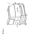
- Fig. 1 is a perspective view illustrating a back portion of a vehicle according to an embodiment
- Fig. 2A is a side view illustrating a door lock apparatus according to the embodiment
- Fig. 2B is a front view illustrating the door lock apparatus according to the embodiment.
- Fig. 3A is a side view illustrating an operation of the door lock apparatus according to the embodiment.
- Fig. 3B is a front view illustrating the operation of the door lock apparatus according to the embodiment.
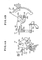
- Fig. 4A is a side view illustrating the operation of the door lock apparatus according to the embodiment.
- Fig. 4B is a front view illustrating the operation of the door lock apparatus according to the embodiment.
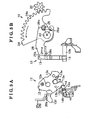
- Fig. 5A is a side view illustrating the operation of the door lock apparatus or according to the embodiment.
- Fig. 5B is a front view illustrating the operation of the door lock apparatus according to the embodiment.
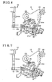
- Fig. 6 is a front view illustrating the operation of the door lock apparatus according to the embodiment.
- Fig. 7 is a front view illustrating the operation of the door lock apparatus according to the embodiment.
- FIG. 1 is a perspective view illustrating a back portion of a vehicle 1.
- an opening portion 2a is formed at a back portion of a body 2 of the vehicle 1.
- a door hinge is provided at an upper portion of the opening portion 2a.
- a back door 3 (which serves as a door of a vehicle) is attached at the back portion of the body 2 of the vehicle 1 via the door hinge so as to be opened and closed.
- a U-shaped striker 4 (see Fig. 2A ) is fixed at a bottom portion of the opening portion 2a.
- the door lock apparatus 10 is provided at an end portion of the back door 3 facing an inside of the vehicle 1.
- the door lock apparatus 10 is provided so as to face the striker 4 and to be engaged therewith.
- the door lock apparatus 10 includes an electric motor 11 (which serves as a driving means).
- the door lock apparatus 10 includes a latch mechanism 12.
- the latch mechanism 12 is supported by the back door 3 via a base plate, which is fixed at the back door 3.
- the latch mechanism 12 includes a latch 13 and a pawl 14.
- First and second pivotal shafts 12a and 12b are provided at the base plate so as to be parallel with each other.
- the latch 13 and the pawl 14 are pivoted around the first and second pivotal shafts 12a and 12b, respectively. Further, the latch mechanism 12 is engaged with and released from the striker 4.
- the latch 13 is formed in a U-shape and includes an engagement recessed portion 13a.
- First and second nail portions 13b and 13c are formed at both sides of the engagement recessed portion 13a (i.e. the first nail portion 13b is formed in an upper left direction of the engagement recessed portion 13a in Fig. 2A and the second nail portion 13c is formed in a lower right direction of the engagement recessed portion 13a in Fig. 2A ).
- a first engagement portion 13d is formed at an end portion of the first nail portion 13b at an opposite side from the engagement recessed portion 13a.
- a second engagement portion 13e is formed at an end portion of the second nail portion 13c at a side of the engagement recessed portion 13a.
- a driven protruding portion 13f is formed at the latch 13 so as to protrude in an opposite direction of the engagement recessed portion 13a across the first pivotal shaft 12a.
- One end of a latch biasing spring is held at the base plate and the other end thereof is engaged with the latch 13.
- the latch 13 is biased by the latch biasing spring so as to be pivoted in a clockwise direction in Fig. 2A .
- an opposing surface 13g of the first nail portion 13b contacts a latch stopper provided at the base plate a pivotal movement of the latch 13 in the clockwise direction is restricted and the latch 13 is held at a first predetermined pivotal position illustrated in Fig. 2A .
- the pawl 14 is connected to a lift lever 16 (see Fig. 2B ) via the second pivotal shaft 12b.
- the pawl 14 is pivoted integrally with the lift lever 16 about the second pivotal shaft 12b.
- the pawl 14 includes an engagement end portion 14a and an extending end portion 14b.
- the engagement end portion 14a extends from the second pivotal shaft 12b in one direction (i.e. in a rightward direction in Fig. 2A ).
- the extending end portion 14b extends from the second pivotal shaft 12b in an opposite direction (i.e. in a leftward direction in Fig. 2A ).
- One end of a pawl biasing spring is held at the base plate and the other end thereof is engaged with the pawl 14.
- the pawl 14 is biased by the pawl biasing spring so as to be pivoted in a counter-clockwise direction in Fig. 2A (i.e. in a direction where the engagement end portion 14a is raised upward). Further, when a stopper contacting portion 16a of the lift lever 16 contacts a stopper 39 provided at the base plate, a pivotal movement of the pawl 14 in the counter-clockwise direction is restricted and the pawl 14 is held at a second predetermined pivotal position illustrated in Fig. 2A .
- a basic operation of the latch mechanism 12 will be described hereinbelow.
- the latch 13 is held at the first predetermined pivotal position because the opposing surface 13g of the first nail portion 13b contacts the latch stopper. Therefore, when the back door 3 is being closed, the striker 4 approaches the engagement recessed portion 13a. Further, the pawl 14 is held at the second predetermined pivotal position because the lift lever 16 contacts the stopper 39. The engagement end portion 14a is positioned below the second nail portion 13c.
- the above-described state of the latch mechanism 12 is an unlatched state (a released state).
- the striker 4 When the back door 3 is operated to close, the striker 4 approaches the engagement recessed portion 13a. Accordingly, an inner wall surface of the engagement recessed portion 13a is thrust by the striker 4. Therefore, the latch 13 is pivoted in the counter-clockwise direction in Fig. 2A against the latch biasing spring until the engagement end portion 14a is engaged with the second engagement portion 13e.
- the back door 3 In the above-described state, the back door 3 is in a half-closed state where the engagement recessed portion 13a is engaged with the striker 4 that is prevented from being released therefrom. In such a state, the latch mechanism 12 is in a half-latched state.
- the striker 4 When the back door 3 is further operated to close, the striker 4 further approaches the engagement recessed portion 13a. Accordingly, the inner wall surface of the engagement recessed portion 13a is further thrust by the striker 4. Therefore, the latch 13 is pivoted in a counter-clockwise direction in Fig. 3A against the latch biasing spring until the engagement end portion 14a is engaged with the first engagement portion 13d (see Fig. 3A ).
- the back door 3 In the above-described state, the back door 3 is in a closed state where the engagement recessed portion 13a is engaged with the striker 4 that is prevented from being further pivoted. In such a state, the latch mechanism 12 is in a fully latched state (an engaged state).
- the door lock apparatus 10 includes a bracket 21.
- the bracket 21 is fixed at the back door 3 and is made of a metal plate.
- a pinion 22 is arranged at the bracket 21.
- the pinion 22 is connected to an output shaft of the electric motor 11 so as to be integrally rotatable.
- a sectoral-shaped active lever 24 (which serves as a first lever or a driving lever) is made of a metal plate and is connected at the bracket 21 so as to be pivotable around a third pivotal shaft 23.
- the third pivotal shaft 23 extends in a different direction from axes of the first and second pivotal shafts 12a and 12b of the latch 13 and the pawl 14.
- the third pivotal shaft 23 extends in a direction parallel with a rational axis of the pinion 22.
- the active lever 24 includes an arc-shaped gear portion 24a, which is engaged with the pinion 22. Therefore, a pivotal position of the active lever 24 is held by means of an engagement between the active lever 24 and the pinion 22.
- the active lever 24 is held at a predetermined pivotal position (which will be hereinbelow referred to as an initial position and which serves as a first initial position), where the gear portion 24a is engaged with the pinion 22 at a substantially intermediate position in a circumferential direction of the gear portion 24a.
- an active lever pin 25 (which serves as an engagement portion or as an engagement pin) is provided at the active lever 24 in the vicinity of the third pivotal shaft 23 so as to protrude parallel with the third pivotal shaft: 23 in a thickness direction of the active lever 24 (i.e. in a direction vertical to the paper surface of Fig. 2B )
- a passive lever 26 (which serves as a second lever or as a closing lever), which is made of a metal plate, is connected to the bracket 21 so as to be pivotable around the third pivotal shaft 23.
- the passive lever 26 includes a first lever portion 26a and a first thrusting strip 26b.
- the first lever portion 26a extends from the third pivotal shaft 23 in a radial direction of the pivotal shaft 23.
- the fist thrusting strip 26b is formed by bending an end portion of the first lever portion 26a.
- the driven protruding portion 13f of the latch 13 is provided at a position on a pivotal locus along which the first thrusting strip 26b pivots around the third pivotal shaft 23 in a counter-clockwise direction in Fig. 2B .
- a first engagement strip 26c is provided at a base end portion of the passive lever 26. More specifically, the first engagement strip 26c is provided at a position on a pivotal locus along which the active lever pin 25 is pivoted about the third pivotal shaft 23 in the counter-clockwise direction in Fig. 2B .
- a second engagement strip 26d (which serves as an engagement strip) is provided at the base end portion of the passive lever 26. More specifically, the second engagement strip 26d is provided at a position on a pivotal locus along which the active lever pin 25 is pivoted about the third pivotal shaft 23 in a clockwise direction in Fig. 2B .
- One end of a first returning spring (which serves as a biasing means or as a closing lever biasing means) is engaged with the bracket 21.
- the other end of the first returning spring is engaged with the passive lever 26. Therefore, the passive lever 26 is biased by the first returning spring so as to be pivoted in the clockwise direction in Fig. 2B .
- a pivotal movement of the passive lever 26 in such direction is restricted when an opposing surface of the first thrusting strip 26b contacts a passive lever stopper 21a, which is provided at the bracket 21.
- the passive lever 26 is held at a predetermined pivotal position (which will be hereinbelow referred to as a closing operation initial position and which serves as a second initial position), illustrated in Fig. 2B .
- the active lever pin 25 is arranged between the first and second engagement strips 26c and 26d in a circumferential direction defined by a rotational locus of the passive lever 26 centering the third pivotal shaft 23. Therefore, when the active lever 24 is pivoted in the counter-clockwise direction in Fig. 2B , the first engagement strip 26c of the passive lever 26 is thrust by the active lever pin 25. Accordingly, the passive lever 26 is pivoted in the counter-clockwise direction in Fig. 2B . As a result, in the above-described manner, the latch mechanism 12 is switched to the fully latched state (see Fig. 3A ).
- the active lever pin 25 thrusts the second engagement strip 26d when the active lever 24 is pivoted back to the initial position (see Fig. 4B ). Therefore, even when the passive lever 26 is tightly engaged with the latch 13 and constrained so as not to be capable of returning back to the closing operation initial position, in accordance with a pivotal movement of the active lever 24 back to the initial position, the second engagement strip 26d is thrust by the active lever pin 25 (see Fig. 4B ), and thereby a constraint state of the passive lever 26 is released. Accordingly, the passive lever 26 is smoothly pivoted back to the closing operation initial position, biased by the first returning spring.
- a bell crank 32 (which serves as a second lever or as a releasing lever), which is made of a metal-plate, is connected to the bracket 21 so as to be pivotable around a fourth pivotal shaft 31.
- the fourth pivotal shaft 31 is provided to be parallel with the third pivotal shaft 23.
- the bell crank 32 includes a second lever portion 32a and a third lever portion 32b.
- the second lever portion 32a extends from the fourth pivotal shaft 31 in a radial direction of the fourth pivotal shaft 31 (i.e. in an upper left direction relative to the fourth pivotal shaft 31 in Fig. 2B ).
- the third lever portion 32b extends from the fourth pivotal shaft 31 in another radial direction of the fourth pivotal shaft 31 (i.e.
- the second lever portion 32a is provided at a position on a pivotal locus along which the active lever pin 25 is pivoted around the third pivotal shaft 23 in the clockwise direction in Fig. 2B .
- the active lever pin 25 thrusts the second lever portion 32a. Therefore, the bell crank 32 is pivoted in the counter-clockwise direction in Fig. 2B .
- pivotal directions of the active lever 24 and the bell crank 32 are opposite from each other.
- the bell crank 32 When the bell crank 32 is thrust by the active lever pin 25, the bell crank 32 is pivoted in the counter-clockwise direction from a position of the bell crank 32 in Fig. 2B , Then, the bell crank 32 is positioned to space away from a portion of the bracket 21, which is formed by bending the bracket 21 in a thickness direction thereof. Thus, the bell crank 32 is positioned at a releasing operation initial position (which serves as a second initial position). More specifically, the releasing operation initial position is where the active lever pin 25 thrusts the bell crank 32 in the counter-clockwise direction in Fig. 2B , accordingly the bell crank 32 thrusts an opening lever 34 (which serves as a third lever), and therefore a switch thrusting portion 34d is positioned to be spaced away from the switch 38.
- the bell crank 32 includes a protruding portion 32c (which serves as an engagement strip) and a second thrusting strip 32d.
- the protruding portion 32c is protruding in a radial direction of the fourth pivotal shaft 31 and is provided so as to be adjacent to the second lever portion 32a.
- the second thrusting strip 32d is formed by bending an end portion of the third lever portion 32b.
- the opening lever 34 which is made of a metal-plate, is connected to the bracket 21 so as to be pivotable around a fifth pivotal shaft 33.
- the fifth pivotal shaft 33 is provided so as to be parallel to the third and fourth pivotal shafts 23 and 31.
- the opening lever 34 includes fourth and fifth lever portions 34a and 34b.
- the fourth lever portion 34a extends in one direction from the fifth pivotal shaft 33 (i.e. in an upper direction relative to the fifth pivotal shaft 33 in Fig. 2B ).
- the fifth lever portion 34b extends in another direction from the fifth pivotal shaft 33 (i.e. in a lower left direction relative to the fifth pivotal shaft 33 in Fig. 2B ).
- the fourth lever portion 34a is provided at a position on a locus along which the second thrusting strip 32d is pivoted in the counter-clockwise direction in Fig. 2B .
- the second thrusting strip 32d thrusts the fourth lever portion 34a.
- the opening lever 34 is pivoted in the clockwise direction in Fig. 2B .
- pivotal directions of the bell crank 32 and the opening lever 34 are opposite from each other and pivotal directions of the active lever 24 and the opening lever 34 are the same.
- the opening lever 34 includes a third thrusting strip 34c, which is formed by bending an end portion of the fifth lever portion 34b.
- the lift lever 16 is provided at a position on a pivotal locus along which the fifth lever portion 34b is pivoted around the fifth pivotal shaft 33 in the clockwise direction in Fig.2B . Therefore, when the latch mechanism 12 is in the fully latched state (see Figs. 5A and 5B ), the opening lever 34 is pivoted in a clockwise direction in Fig. 5B . Then, the lift lever 16 is thrust by the third thrusting strip 34c. Accordingly, the lift lever 16 and the pawl 14 are pivoted in a clockwise direction in Fig. 5A . In the above-described manner, an engagement between the pawl 14 and the latch 13 is released. Thus, the latch mechanism 12 is switched to the unlatched state.
- a third engagement strip 21c is formed at the bracket 21.
- One end of a second returning spring 35 (which serves as a biasing means or as a releasing lever biasing means) is engaged with the third engagement strip 21c.
- the other end of the second returning spring 35 is engaged with the fourth lever portion 34a of the opening lever 34. Therefore, the opening lever 34 is biased in the counter-clockwise direction in Fig. 2B .
- the second thrusting strip 32d of the bell crank 32 whose pivotal movement is restricted at the releasing operation initial position, contacts an opposing surface of the fourth lever portion 34a, a pivotal movement of the opening lever 34 in the counter-clockwise direction in Fig. 2B is restricted.
- the opening lever 34 is held at a predetermined pivotal position (which serves as a third initial position or as an opening operation initial position).
- the bell crank 32 is held at the releasing operation initial position, biased by the second returning spring 35 via the opening lever 34.
- the active lever pin 25 is arranged between the second lever portion 32a and the protruding portion 32c in a circumferential direction defined by a rotational locus of the bell crank 32 centering the fourth pivotal shaft 31.
- the active lever pin 25 thrusts the protruding portion 32c when the active lever 24 is pivoted back to the initial position (see Fig. 7 ). Therefore, even when the bell crank 32 is tightly engaged with the opening lever 34 and constrained so as not to be capable of returning back to the releasing operation initial position, in accordance with a pivotal movement of the active lever 24 back to the initial position, the protruding portion 32c is thrust by the active lever pin 25 (see Fig. 7 ), and thereby a constraint of the bell crank 32 is released. Accordingly, the bell crank 32 is smoothly pivoted back to the releasing operation initial position, biased by the second returning spring 35 via the opening lever 34.
- the passive lever 26 is, for example, tightly engaged with the latch 13 and constrained so as not to be capable of returning back to the closing operation initial position. While the passive lever 26 is in such a state, the active lever 24 is pivoted back to the initial position. Then, the active lever pin 25 thrusts the second engagement strip 26d of the passive lever 26, and thereby the constraint of the passive lever 26 is released. Accordingly, the passive lever 26 is smoothly pivoted back to the closing operation initial position, biased by the first returning spring. Thus, the latch mechanism 12 is prevented from malfunctioning.
- the pinion 22 is rotated in the counter-clockwise direction in Fig. 5B .
- the active lever 24 is pivoted in the clockwise direction in Fig. 5B from the initial position.
- the pivotal movement of the active lever pin 25, which is integrally formed at the active lever 24, is transmitted to the lift lever 16 via the bell crank 32 and the opening lever 34.
- the lift lever 16 is pivoted in a clockwise direction in Fig. 5A together with the pawl 14.
- the latch 13 is released from the pawl 14.
- the striker 4 is released from the latch 13.
- the latch mechanism 12 is switched to the unlatched state. Accordingly, the back door 3 can be opened.
- the bell crank 32 is, for example, tightly engaged with the opening lever 34 and constrained so as not to be capable of returning back to the releasing operation initial position. While the bell crane 32 is in such a state, the active lever 24 is pivoted back to the initial position. Then, the active lever pin 25 thrusts the protruding portion 32c of the bell crank 32, and thereby the constraint of the bell crank 32 is released. Accordingly, the bell crank 32 is smoothly pivoted back to the releasing operation initial position, biased by the second returning spring 35. Thus, the latch mechanism 12 is prevented from malfunctioning.
- the passive lever 26, which has switched the latch mechanism 12 from the unlatched state to the fully latched state, may be constrained so as not to return back to the closing operation initial position. Then, in accordance with the pivotal movement of the active lever 24 back to the initial position, the active lever pin 25 thrusts the second engagement strip 26d of the passive lever 26. Accordingly, the constraint of the passive lever 26 is released. Therefore, the passive lever 26 is pivoted back to the closing operation initial position, biased by the first returning spring. As a result, such malfunction that the latch mechanism 12 fails to be switched to a subsequent state, due to the constraint of the passive lever 26, is prevented.
- the bell crank 32 which has switched the latch mechanism 12 from the fully latched state to the unlatched state, may be constrained so as not to return back to the releasing operation initial position. Then, in accordance with the pivotal movement of the active lever 24 back to the initial position, the active lever pin 25 thrusts the protruding portion 32c of the bell crank 32. Accordingly, the constraint of the bell crank 32 is released. Therefore, the bell crank 32 is pivoted back to the releasing operation initial position, biased by the second returning spring 35. As a result, such malfunction that the latch mechanism 12 fails to be switched to a subsequent state, due to the constraint of the bell crank 32, is prevented.
- a reliability of the door lock apparatus 10 is improved.
- a pivotal direction of the active lever 24 is changed by means of the bell crank 32 before the pivotal movement of the active lever 24 is transmitted to the opening lever 34. Further, the state of the latch mechanism 12 is switched by the bell crank 32 via the opening lever 34. Therefore, sizes and structures of the bell crank 32, the opening lever 34, the lift lever 26, and the like related to the pivotal transmission, for example, are prevented from being enlarged and being complicated, respectively. Accordingly, components may be freely arranged and can be easily mounted.
- the active lever pin 25 for establishing transmission and operative connection between the active lever 24 and the passive lever 26 (between the active lever 24 and the bell crank 32) also serves as an engagement portion for preventing the malfunction of the latch mechanism 12. Therefore, the number of components is decreased.
- a known separation means may be provided either between the electric motor 11 and the passive lever 26 or between the electric motor 11 and the opening lever 34.
- the separation means manually disconnects a mechanical connection therebetween. Therefore, even when the electric motor 11 malfunctions, the constraint of either passive lever 26 or the opening lever 34 due to the malfunction of the electric motor 11 mary be manually released. Therefore, the latch mechanism 12 is prevented from malfunctioning. Then, the back door 3 can be opened and closed.
- the bell crank 32 may directly operate the lift lever 16, without arranging the opening lever 34 therebetween.
- a returning spring returning the bell crank 32 to the releasing operation initial position may directly bias the bell crank 32.
- the latch mechanism 12 (the door lock apparatus 10) may be provided at the body 2 of the vehicle 1.
- the striker 4 may be provided at the back door 3 of the vehicle 1.
Landscapes
- Lock And Its Accessories (AREA)
Abstract
Description
- The present invention relates to a door lock apparatus for a vehicle.
- A known door lock apparatus for a vehicle is disclosed in
JP62101782 - According to the door lock apparatus in reference 1, a lever, which transmits a force of the actuator to the latch mechanism, may be tightly engaged with a member and constrained in a position obtained when the lever switches the state of the latch mechanism. In such a case, the lever may not return to a previous state where the state of the latch mechanism has not yet switched. Therefore, the latch mechanism may malfunction.
- A need thus exists for a door lock apparatus for a vehicle for preventing a latch mechanism from malfunctioning.
- According to an aspect of the present invention, a door lock apparatus for a vehicle includes a latch mechanism provided at one of a body of the vehicle and a door of the vehicle, and engaged with and released from a striker provided at the other one of the body of the vehicle and the door of the vehicle, a first lever rotatably driven by a driving means from a predetermined first initial position, a second lever operatively connected to the first lever and rotated from a predetermined second initial position in accordance with a rotational movement of the first lever from the first initial position, the second lever switching the latch mechanism between engaged and released states relative to the striker, a biasing means biasing the second lever to be returned to the second initial position in accordance with the rotational movement of the first lever returning to the first initial position, and an engagement portion provided at the first lever and releasing the second lever by thrusting the second lever in accordance with the rotational movement of the first lever returning to the first initial position, from a constrained state where the second lever is constrained not to be returned to the second initial position after the second lever has changed the states of the latch mechanism.
- Accordingly, the second, which has switched the latch mechanism from the unlatched state to the fully latched state, may be constrained so as not to return back to the second initial position. Then, in accordance with the pivotal movement of the first lever back to the initial position, the engagement portion thrusts the second engagement strip of the second lever. Accordingly, the constraint of the second lever is released. Therefore, the second lever is pivoted back to the second initial position, biased by the biasing means. As a result, such malfunction that the latch mechanism fails to be switched to a subsequent state, due to the constraint of the second lever, is prevented.
- According to another aspect of the invention, the door lock apparatus further includes a third lever operatively connected to the second lever and rotated from a predetermined third initial position in accordance with a rotational movement of the second lever from the second initial position, wherein the second lever transmits the rotational movement of the first lever to the third lever so as to change a rotational direction of the first lever, and the second lever switches the state of the latch mechanism via the third lever.
- Accordingly, a pivotal direction of the first lever is changed by means of the second lever before the pivotal movement of the first lever is transmitted to the third lever. Further, the state of the latch mechanism is switched by the second lever via the third lever. Therefore, sizes and structures of the second lever, the third lever, the lift lever, and the like related to the pivotal transmission, for example, are prevented from being enlarged and being complicated, respectively. Accordingly, components may be freely arranged and can be easily mounted.
- According to another aspect of the invention, the door lock apparatus for a vehicle further includes a driving lever serving as the first lever and rotatably driven by the driving means from the first initial position in first and second directions, closing lever serving as the second lever, operatively connected to the driving lever and rotated from a predetermined closing operation initial position serving as the second initial position in accordance with the rotational movement of the driving lever from the first initial position in the first direction to switch the state of the latch mechanism from the engaged state to the released state relative to the striker; the closing lever biasing means biasing the closing lever to be returned to the closing operation initial position in accordance with the rotational movement of the driving lever returning to the first initial position; a releasing lever serving as the second lever, operatively connected to the driving lever and rotated from a predetermined releasing operation initial position serving as the second initial position in accordance with the rotational movement of the driving lever from the first initial position in the second direction to switch the latch mechanism from the engaged state with the striker and the released state from the striker, the releasing lever biasing means rotating the releasing lever back to the releasing operation initial position in accordance with the rotational movement of the driving lever returning to the first initial position; and the engagement portion provided at the driving lever and releasing at least one of the closing lever and the releasing lever in accordance with the rotational movement of the driving lever returning to the first initial position from a constrained state where at least one of the closing lever and the releasing lever is constrained not to be returned to the corresponding initial position after at least one of the closing lever and the releasing lever has changed the states of the latch mechanism.
- According to another aspect of the invention, the door lock apparatus further includes an engagement strip provided at least one of the closing lever and the releasing lever and thrust by the engagement portion, provided at the driving lever, in accordance with the rotational movement of the driving lever returning to the initial position.
- According to another aspect of the invention, the door lock apparatus further includes an engagement strip provided at the second lever and thrust by the engagement portion, provided at the first lever, in accordance with the rotational movement of the first lever returning to the first initial position.
- According to another aspect of the invention, the release lever is a bell crank.
- According to another aspect of the invention, the engagement portion of the driving lever is an engagement pin thrusting the engagement strip.
- According to another aspect of the invention, the door lock apparatus further includes an opening lever operatively connected to the releasing lever and rotated from an opening operation initial position in accordance with a rotational movement of the releasing lever from the releasing lever initial position, wherein the releasing lever transmits the rotational movement of the driving lever to the opening lever so as to change a rotational direction of the driving lever, and the releasing lever switches the state of the latch mechanism via the opening lever.
- The foregoing and additional features and characteristics of the present invention will become more apparent from the following detailed description considered with the reference to the accompanying drawings, wherein:
-
Fig. 1 is a perspective view illustrating a back portion of a vehicle according to an embodiment; -
Fig. 2A is a side view illustrating a door lock apparatus according to the embodiment; -
Fig. 2B is a front view illustrating the door lock apparatus according to the embodiment; -
Fig. 3A is a side view illustrating an operation of the door lock apparatus according to the embodiment; -
Fig. 3B is a front view illustrating the operation of the door lock apparatus according to the embodiment; -
Fig. 4A is a side view illustrating the operation of the door lock apparatus according to the embodiment; -
Fig. 4B is a front view illustrating the operation of the door lock apparatus according to the embodiment; -
Fig. 5A is a side view illustrating the operation of the door lock apparatus or according to the embodiment; -
Fig. 5B is a front view illustrating the operation of the door lock apparatus according to the embodiment; -
Fig. 6 is a front view illustrating the operation of the door lock apparatus according to the embodiment; and -
Fig. 7 is a front view illustrating the operation of the door lock apparatus according to the embodiment. - An embodiment of a
door lock apparatus 10 will be described hereinbelow with reference to the attached drawings.Fig. 1 is a perspective view illustrating a back portion of a vehicle 1. As illustrated inFig. 1 , anopening portion 2a is formed at a back portion of abody 2 of the vehicle 1. A door hinge is provided at an upper portion of theopening portion 2a. A back door 3 (which serves as a door of a vehicle) is attached at the back portion of thebody 2 of the vehicle 1 via the door hinge so as to be opened and closed. A U-shaped striker 4 (seeFig. 2A ) is fixed at a bottom portion of theopening portion 2a. Thedoor lock apparatus 10 is provided at an end portion of the back door 3 facing an inside of the vehicle 1. Thedoor lock apparatus 10 is provided so as to face the striker 4 and to be engaged therewith. Further, thedoor lock apparatus 10 includes an electric motor 11 (which serves as a driving means). - As illustrated in
Figs. 2A and 2B , thedoor lock apparatus 10 includes alatch mechanism 12. Thelatch mechanism 12 is supported by the back door 3 via a base plate, which is fixed at the back door 3. Thelatch mechanism 12 includes alatch 13 and apawl 14. First and secondpivotal shafts latch 13 and thepawl 14 are pivoted around the first and secondpivotal shafts latch mechanism 12 is engaged with and released from the striker 4. - More specifically, the
latch 13 is formed in a U-shape and includes an engagement recessedportion 13a. First andsecond nail portions portion 13a (i.e. thefirst nail portion 13b is formed in an upper left direction of the engagement recessedportion 13a inFig. 2A and thesecond nail portion 13c is formed in a lower right direction of the engagement recessedportion 13a inFig. 2A ). Afirst engagement portion 13d is formed at an end portion of thefirst nail portion 13b at an opposite side from the engagement recessedportion 13a. Asecond engagement portion 13e is formed at an end portion of thesecond nail portion 13c at a side of the engagement recessedportion 13a. A driven protrudingportion 13f is formed at thelatch 13 so as to protrude in an opposite direction of the engagement recessedportion 13a across the firstpivotal shaft 12a. One end of a latch biasing spring is held at the base plate and the other end thereof is engaged with thelatch 13. Thelatch 13 is biased by the latch biasing spring so as to be pivoted in a clockwise direction inFig. 2A . Further, when an opposing surface 13g of thefirst nail portion 13b contacts a latch stopper provided at the base plate, a pivotal movement of thelatch 13 in the clockwise direction is restricted and thelatch 13 is held at a first predetermined pivotal position illustrated inFig. 2A . - The
pawl 14 is connected to a lift lever 16 (seeFig. 2B ) via the secondpivotal shaft 12b. Thepawl 14 is pivoted integrally with thelift lever 16 about the secondpivotal shaft 12b. Thepawl 14 includes anengagement end portion 14a and an extendingend portion 14b. Theengagement end portion 14a extends from the secondpivotal shaft 12b in one direction (i.e. in a rightward direction inFig. 2A ). The extendingend portion 14b extends from the secondpivotal shaft 12b in an opposite direction (i.e. in a leftward direction inFig. 2A ). One end of a pawl biasing spring is held at the base plate and the other end thereof is engaged with thepawl 14. Thepawl 14 is biased by the pawl biasing spring so as to be pivoted in a counter-clockwise direction inFig. 2A (i.e. in a direction where theengagement end portion 14a is raised upward). Further, when astopper contacting portion 16a of thelift lever 16 contacts astopper 39 provided at the base plate, a pivotal movement of thepawl 14 in the counter-clockwise direction is restricted and thepawl 14 is held at a second predetermined pivotal position illustrated inFig. 2A . - A basic operation of the
latch mechanism 12 will be described hereinbelow. When the back door 3 is in an opened state, as illustrated inFig. 2A , thelatch 13 is held at the first predetermined pivotal position because the opposing surface 13g of thefirst nail portion 13b contacts the latch stopper. Therefore, when the back door 3 is being closed, the striker 4 approaches the engagement recessedportion 13a. Further, thepawl 14 is held at the second predetermined pivotal position because thelift lever 16 contacts thestopper 39. Theengagement end portion 14a is positioned below thesecond nail portion 13c. The above-described state of thelatch mechanism 12 is an unlatched state (a released state). - When the back door 3 is operated to close, the striker 4 approaches the engagement recessed
portion 13a. Accordingly, an inner wall surface of the engagement recessedportion 13a is thrust by the striker 4. Therefore, thelatch 13 is pivoted in the counter-clockwise direction inFig. 2A against the latch biasing spring until theengagement end portion 14a is engaged with thesecond engagement portion 13e. In the above-described state, the back door 3 is in a half-closed state where the engagement recessedportion 13a is engaged with the striker 4 that is prevented from being released therefrom. In such a state, thelatch mechanism 12 is in a half-latched state. - When the back door 3 is further operated to close, the striker 4 further approaches the engagement recessed
portion 13a. Accordingly, the inner wall surface of the engagement recessedportion 13a is further thrust by the striker 4. Therefore, thelatch 13 is pivoted in a counter-clockwise direction inFig. 3A against the latch biasing spring until theengagement end portion 14a is engaged with thefirst engagement portion 13d (seeFig. 3A ). In the above-described state, the back door 3 is in a closed state where the engagement recessedportion 13a is engaged with the striker 4 that is prevented from being further pivoted. In such a state, thelatch mechanism 12 is in a fully latched state (an engaged state). - In the above-described half-latched or fully latched state, when the
pawl 14 is pivoted in a clockwise direction inFig. 3A against the pawl biasing spring, an engagement between theengagement end portion 14a and thefirst engagement portion 13d or between theengagement end portion 14a and thesecond engagement portion 13e is released. Accordingly, thelatch 13 is biased by the latch biasing spring so as to be pivoted in the clockwise direction inFig. 3A . Therefore, the striker 4 is thrust by the inner wall surface of the engagement recessedportion 13a. As a result, the engagement between theengagement portion 13a and the striker 4 is released, which causes the back door 3 to be opened. - As illustrated in
Fig. 2B , thedoor lock apparatus 10 includes abracket 21. Thebracket 21 is fixed at the back door 3 and is made of a metal plate. Apinion 22 is arranged at thebracket 21. Thepinion 22 is connected to an output shaft of the electric motor 11 so as to be integrally rotatable. A sectoral-shaped active lever 24 (which serves as a first lever or a driving lever) is made of a metal plate and is connected at thebracket 21 so as to be pivotable around a thirdpivotal shaft 23. The thirdpivotal shaft 23 extends in a different direction from axes of the first and secondpivotal shafts latch 13 and thepawl 14. More specifically, the thirdpivotal shaft 23 extends in a direction parallel with a rational axis of thepinion 22. Theactive lever 24 includes an arc-shapedgear portion 24a, which is engaged with thepinion 22. Therefore, a pivotal position of theactive lever 24 is held by means of an engagement between theactive lever 24 and thepinion 22. Normally, as illustrated inFig. 2B , theactive lever 24 is held at a predetermined pivotal position (which will be hereinbelow referred to as an initial position and which serves as a first initial position), where thegear portion 24a is engaged with thepinion 22 at a substantially intermediate position in a circumferential direction of thegear portion 24a. Further, an active lever pin 25 (which serves as an engagement portion or as an engagement pin) is provided at theactive lever 24 in the vicinity of the thirdpivotal shaft 23 so as to protrude parallel with the third pivotal shaft: 23 in a thickness direction of the active lever 24 (i.e. in a direction vertical to the paper surface ofFig. 2B ) - A passive lever 26 (which serves as a second lever or as a closing lever), which is made of a metal plate, is connected to the
bracket 21 so as to be pivotable around the thirdpivotal shaft 23. Thepassive lever 26 includes afirst lever portion 26a and a first thrustingstrip 26b. Thefirst lever portion 26a extends from the thirdpivotal shaft 23 in a radial direction of thepivotal shaft 23. Thefist thrusting strip 26b is formed by bending an end portion of thefirst lever portion 26a. The driven protrudingportion 13f of thelatch 13 is provided at a position on a pivotal locus along which the first thrustingstrip 26b pivots around the thirdpivotal shaft 23 in a counter-clockwise direction inFig. 2B . Therefore, when thepassive lever 26 is pivoted in the counter-clockwise direction inFig. 2B , the driven protrudingportion 13f is thrust by the first thrustingstrip 26b. Accordingly, thelatch 13 is pivoted in the counter-clockwise direction inFig. 2A until thelatch 13 is engaged with the pawl 14 (seeFig. 3A ) in a manner described above. Thus, thelatch mechanism 12 is switched to the fully latched state. - A
first engagement strip 26c is provided at a base end portion of thepassive lever 26. More specifically, thefirst engagement strip 26c is provided at a position on a pivotal locus along which theactive lever pin 25 is pivoted about the thirdpivotal shaft 23 in the counter-clockwise direction inFig. 2B . Likewise, asecond engagement strip 26d (which serves as an engagement strip) is provided at the base end portion of thepassive lever 26. More specifically, thesecond engagement strip 26d is provided at a position on a pivotal locus along which theactive lever pin 25 is pivoted about the thirdpivotal shaft 23 in a clockwise direction inFig. 2B . One end of a first returning spring (which serves as a biasing means or as a closing lever biasing means) is engaged with thebracket 21. The other end of the first returning spring is engaged with thepassive lever 26. Therefore, thepassive lever 26 is biased by the first returning spring so as to be pivoted in the clockwise direction inFig. 2B . A pivotal movement of thepassive lever 26 in such direction is restricted when an opposing surface of the first thrustingstrip 26b contacts apassive lever stopper 21a, which is provided at thebracket 21. Thus, thepassive lever 26 is held at a predetermined pivotal position (which will be hereinbelow referred to as a closing operation initial position and which serves as a second initial position), illustrated inFig. 2B . When thepassive lever 26 is in the closing operation initial position, theactive lever pin 25 is arranged between the first and second engagement strips 26c and 26d in a circumferential direction defined by a rotational locus of thepassive lever 26 centering the thirdpivotal shaft 23. Therefore, when theactive lever 24 is pivoted in the counter-clockwise direction inFig. 2B , thefirst engagement strip 26c of thepassive lever 26 is thrust by theactive lever pin 25. Accordingly, thepassive lever 26 is pivoted in the counter-clockwise direction inFig. 2B . As a result, in the above-described manner, thelatch mechanism 12 is switched to the fully latched state (seeFig. 3A ). - After the
passive lever 26 is located at a pivotal position where thelatch mechanism 12 is switched into the fully latched state, theactive lever pin 25 thrusts thesecond engagement strip 26d when theactive lever 24 is pivoted back to the initial position (seeFig. 4B ). Therefore, even when thepassive lever 26 is tightly engaged with thelatch 13 and constrained so as not to be capable of returning back to the closing operation initial position, in accordance with a pivotal movement of theactive lever 24 back to the initial position, thesecond engagement strip 26d is thrust by the active lever pin 25 (seeFig. 4B ), and thereby a constraint state of thepassive lever 26 is released. Accordingly, thepassive lever 26 is smoothly pivoted back to the closing operation initial position, biased by the first returning spring. - A bell crank 32 (which serves as a second lever or as a releasing lever), which is made of a metal-plate, is connected to the
bracket 21 so as to be pivotable around a fourthpivotal shaft 31. The fourthpivotal shaft 31 is provided to be parallel with the thirdpivotal shaft 23. Thebell crank 32 includes asecond lever portion 32a and athird lever portion 32b. Thesecond lever portion 32a extends from the fourthpivotal shaft 31 in a radial direction of the fourth pivotal shaft 31 (i.e. in an upper left direction relative to the fourthpivotal shaft 31 inFig. 2B ). Thethird lever portion 32b extends from the fourthpivotal shaft 31 in another radial direction of the fourth pivotal shaft 31 (i.e. in a lower direction relative to the fourthpivotal shaft 31 inFig. 2B ). Thesecond lever portion 32a is provided at a position on a pivotal locus along which theactive lever pin 25 is pivoted around the thirdpivotal shaft 23 in the clockwise direction inFig. 2B . When theactive lever 24 and theactive lever pin 25 are pivoted in the clockwise direction inFig. 2B , theactive lever pin 25 thrusts thesecond lever portion 32a. Therefore, the bell crank 32 is pivoted in the counter-clockwise direction inFig. 2B . In other words, pivotal directions of theactive lever 24 and the bell crank 32 are opposite from each other. - When the bell crank 32 is thrust by the
active lever pin 25, the bell crank 32 is pivoted in the counter-clockwise direction from a position of the bell crank 32 inFig. 2B , Then, the bell crank 32 is positioned to space away from a portion of thebracket 21, which is formed by bending thebracket 21 in a thickness direction thereof. Thus, the bell crank 32 is positioned at a releasing operation initial position (which serves as a second initial position). More specifically, the releasing operation initial position is where theactive lever pin 25 thrusts the bell crank 32 in the counter-clockwise direction inFig. 2B , accordingly the bell crank 32 thrusts an opening lever 34 (which serves as a third lever), and therefore aswitch thrusting portion 34d is positioned to be spaced away from theswitch 38. Further, the bell crank 32 includes a protrudingportion 32c (which serves as an engagement strip) and a second thrustingstrip 32d. The protrudingportion 32c is protruding in a radial direction of the fourthpivotal shaft 31 and is provided so as to be adjacent to thesecond lever portion 32a. The second thrustingstrip 32d is formed by bending an end portion of thethird lever portion 32b. - The opening
lever 34, which is made of a metal-plate, is connected to thebracket 21 so as to be pivotable around a fifthpivotal shaft 33. The fifthpivotal shaft 33 is provided so as to be parallel to the third and fourthpivotal shafts lever 34 includes fourth andfifth lever portions 34a and 34b. The fourth lever portion 34a extends in one direction from the fifth pivotal shaft 33 (i.e. in an upper direction relative to the fifthpivotal shaft 33 inFig. 2B ). Thefifth lever portion 34b extends in another direction from the fifth pivotal shaft 33 (i.e. in a lower left direction relative to the fifthpivotal shaft 33 inFig. 2B ). The fourth lever portion 34a is provided at a position on a locus along which the second thrustingstrip 32d is pivoted in the counter-clockwise direction inFig. 2B . When the bell crank 32 is pivoted in the counter-clockwise direction inFig. 2B , the second thrustingstrip 32d thrusts the fourth lever portion 34a. Accordingly, the openinglever 34 is pivoted in the clockwise direction inFig. 2B . In other words, pivotal directions of the bell crank 32 and theopening lever 34 are opposite from each other and pivotal directions of theactive lever 24 and theopening lever 34 are the same. - The opening
lever 34 includes a third thrustingstrip 34c, which is formed by bending an end portion of thefifth lever portion 34b. Thelift lever 16 is provided at a position on a pivotal locus along which thefifth lever portion 34b is pivoted around the fifthpivotal shaft 33 in the clockwise direction inFig.2B . Therefore, when thelatch mechanism 12 is in the fully latched state (seeFigs. 5A and 5B ), the openinglever 34 is pivoted in a clockwise direction inFig. 5B . Then, thelift lever 16 is thrust by the third thrustingstrip 34c. Accordingly, thelift lever 16 and thepawl 14 are pivoted in a clockwise direction inFig. 5A . In the above-described manner, an engagement between thepawl 14 and thelatch 13 is released. Thus, thelatch mechanism 12 is switched to the unlatched state. - A
third engagement strip 21c is formed at thebracket 21. One end of a second returning spring 35 (which serves as a biasing means or as a releasing lever biasing means) is engaged with thethird engagement strip 21c. The other end of the second returningspring 35 is engaged with the fourth lever portion 34a of the openinglever 34. Therefore, the openinglever 34 is biased in the counter-clockwise direction inFig. 2B . When the second thrustingstrip 32d of the bell crank 32, whose pivotal movement is restricted at the releasing operation initial position, contacts an opposing surface of the fourth lever portion 34a, a pivotal movement of the openinglever 34 in the counter-clockwise direction inFig. 2B is restricted. Thus, as illustrated inFig. 2B , the openinglever 34 is held at a predetermined pivotal position (which serves as a third initial position or as an opening operation initial position). In other words, the bell crank 32 is held at the releasing operation initial position, biased by the second returningspring 35 via theopening lever 34. Further, when the bell crank 32 is at the releasing operation initial position, theactive lever pin 25 is arranged between thesecond lever portion 32a and the protrudingportion 32c in a circumferential direction defined by a rotational locus of the bell crank 32 centering the fourthpivotal shaft 31. - Therefore, when the
active lever 24 is pivoted in the clockwise direction inFig. 2B , theactive lever pin 25 thrusts thesecond lever portion 32a. Then, the bell crank 32 is pivoted in the counter-clockwise direction inFig. 2B . Accordingly, the second thrustingstrip 32d thrusts the fourth lever portion 34a. Then, the openinglever 34 is pivoted in the clockwise direction inFig. 2B (seeFig. 6 ). As a result, in the manner described above, thelatch mechanism 12 is switched to the unlatched state. - After the bell crank 32 is located at a pivotal position where the
latch mechanism 12 is switched into the unlatched state via theopening lever 34, theactive lever pin 25 thrusts the protrudingportion 32c when theactive lever 24 is pivoted back to the initial position (seeFig. 7 ). Therefore, even when the bell crank 32 is tightly engaged with the openinglever 34 and constrained so as not to be capable of returning back to the releasing operation initial position, in accordance with a pivotal movement of theactive lever 24 back to the initial position, the protrudingportion 32c is thrust by the active lever pin 25 (seeFig. 7 ), and thereby a constraint of the bell crank 32 is released. Accordingly, the bell crank 32 is smoothly pivoted back to the releasing operation initial position, biased by the second returningspring 35 via theopening lever 34. - An operation of the
door lock apparatus 10 according to the embodiment will be described hereinbelow. While thelatch mechanism 12 is in the unlatched state as illustrated inFigs. 2A and 2B , the striker 4 approaches the engagement recessedportion 13a of thelatch 13 in accordance with a closing operation of the back door 3. Then, thepinion 22 is rotated in the clockwise direction inFig. 2B . Theactive lever 24 is pivoted from the initial position in the counter-clockwise direction inFig. 2B . A pivotal movement of theactive lever pin 25, which is integrally formed at theactive lever 24, is transmitted to thelatch 13 via thepassive lever 26. Thelatch 13 is pivoted in the counter-clockwise direction inFig. 2A , engaging the striker 4 which is located at the engagement recessedportion 13a. Then, in the above-described manner, thelatch 13 is engaged with thepawl 14 and prevented from being further pivoted (seeFig. 3A ). Thus, thelatch mechanism 12 is switched to the fully latched state. The back door 3 is held in a fully closed state. - Subsequently, when the
pinion 22 is rotated in a counter-clockwise direction inFig. 3B , theactive lever 24 is pivoted in a clockwise direction inFig. 3B to return back to the initial position. Thepassive lever 26 is released from theactive lever pin 25, Normally, thepassive lever 26 is pivoted back to the closing operation initial position biased by the first returning spring. Thus, thelatch 13 is released from thepassive lever 26. - On the other hand, as illustrated in
Figs. 4A and 4B , thepassive lever 26 is, for example, tightly engaged with thelatch 13 and constrained so as not to be capable of returning back to the closing operation initial position. While thepassive lever 26 is in such a state, theactive lever 24 is pivoted back to the initial position. Then, theactive lever pin 25 thrusts thesecond engagement strip 26d of thepassive lever 26, and thereby the constraint of thepassive lever 26 is released. Accordingly, thepassive lever 26 is smoothly pivoted back to the closing operation initial position, biased by the first returning spring. Thus, thelatch mechanism 12 is prevented from malfunctioning. - Further, while the
latch mechanism 12 is in the fully latched state as illustrated inFigs. 5A and 5B , thepinion 22 is rotated in the counter-clockwise direction inFig. 5B . Theactive lever 24 is pivoted in the clockwise direction inFig. 5B from the initial position. The pivotal movement of theactive lever pin 25, which is integrally formed at theactive lever 24, is transmitted to thelift lever 16 via the bell crank 32 and theopening lever 34. Thelift lever 16 is pivoted in a clockwise direction inFig. 5A together with thepawl 14. Then, in the above-described manner, thelatch 13 is released from thepawl 14. The striker 4 is released from thelatch 13. Thus, thelatch mechanism 12 is switched to the unlatched state. Accordingly, the back door 3 can be opened. - Subsequently, when the
pinion 22 is rotated in a clockwise direction inFig. 6 , theactive lever 24 is pivoted in a counter-clockwise direction inFig. 6 to return back to the initial position. Thebell crank 32 is released from theactive lever pin 25.
Normally, the bell crank 32 is pivoted back to the releasing operation initial position biased by the second returningspring 35 via theopening lever 34. Thus, thelift lever 16 is released from the openinglever 34. - On the other hand, as illustrated in
Figs. 7A and 7B , the bell crank 32 is, for example, tightly engaged with the openinglever 34 and constrained so as not to be capable of returning back to the releasing operation initial position. While thebell crane 32 is in such a state, theactive lever 24 is pivoted back to the initial position. Then, theactive lever pin 25 thrusts the protrudingportion 32c of the bell crank 32, and thereby the constraint of the bell crank 32 is released. Accordingly, the bell crank 32 is smoothly pivoted back to the releasing operation initial position, biased by the second returningspring 35. Thus, thelatch mechanism 12 is prevented from malfunctioning. - As described above, the following effects may be obtained according to the embodiment. The
passive lever 26, which has switched thelatch mechanism 12 from the unlatched state to the fully latched state, may be constrained so as not to return back to the closing operation initial position. Then, in accordance with the pivotal movement of theactive lever 24 back to the initial position, theactive lever pin 25 thrusts thesecond engagement strip 26d of thepassive lever 26. Accordingly, the constraint of thepassive lever 26 is released. Therefore, thepassive lever 26 is pivoted back to the closing operation initial position, biased by the first returning spring. As a result, such malfunction that thelatch mechanism 12 fails to be switched to a subsequent state, due to the constraint of thepassive lever 26, is prevented. - According to the embodiment, the bell crank 32, which has switched the
latch mechanism 12 from the fully latched state to the unlatched state, may be constrained so as not to return back to the releasing operation initial position. Then, in accordance with the pivotal movement of theactive lever 24 back to the initial position, theactive lever pin 25 thrusts the protrudingportion 32c of thebell crank 32. Accordingly, the constraint of the bell crank 32 is released. Therefore, the bell crank 32 is pivoted back to the releasing operation initial position, biased by the second returningspring 35. As a result, such malfunction that thelatch mechanism 12 fails to be switched to a subsequent state, due to the constraint of the bell crank 32, is prevented. - Thus, a reliability of the
door lock apparatus 10 is improved. According to the embodiment, a pivotal direction of theactive lever 24 is changed by means of the bell crank 32 before the pivotal movement of theactive lever 24 is transmitted to theopening lever 34. Further, the state of thelatch mechanism 12 is switched by the bell crank 32 via theopening lever 34. Therefore, sizes and structures of the bell crank 32, the openinglever 34, thelift lever 26, and the like related to the pivotal transmission, for example, are prevented from being enlarged and being complicated, respectively. Accordingly, components may be freely arranged and can be easily mounted. - According to the embodiment, the
active lever pin 25 for establishing transmission and operative connection between theactive lever 24 and the passive lever 26 (between theactive lever 24 and the bell crank 32) also serves as an engagement portion for preventing the malfunction of thelatch mechanism 12. Therefore, the number of components is decreased. - Further, the above-described embodiment may be changed as follows: A known separation means (see
JP8218710A passive lever 26 or between the electric motor 11 and theopening lever 34. The separation means manually disconnects a mechanical connection therebetween. Therefore, even when the electric motor 11 malfunctions, the constraint of eitherpassive lever 26 or theopening lever 34 due to the malfunction of the electric motor 11 mary be manually released. Therefore, thelatch mechanism 12 is prevented from malfunctioning. Then, the back door 3 can be opened and closed. - In a case where the bell crank 32 is operatively connectable with the
left lever 16, the bell crank 32 may directly operate thelift lever 16, without arranging the openinglever 34 therebetween. In such a case, a returning spring returning the bell crank 32 to the releasing operation initial position may directly bias thebell crank 32. - The latch mechanism 12 (the door lock apparatus 10) may be provided at the
body 2 of the vehicle 1. In such a case, the striker 4 may be provided at the back door 3 of the vehicle 1.
Claims (8)
- A door lock apparatus for a vehicle (10) comprising:a latch mechanism (12) provided at one of a body (2) of the vehicle and a door (3) of the vehicle, and engaged with and released from a striker (4) provided at the other one of the body (2) of the vehicle and the door (3) of the vehicle;a first lever (24) rotatably driven by a driving means (11) from a predetermined first initial position;a second lever (26, 32) operatively connected to the first lever (24) and rotated from a predetermined second initial position in accordance with a rotational movement of the first lever (24) from the first initial position to switch the latch mechanism (12) between engaged and released states relative to the striker (4);a biasing means (35) biasing the second lever (26, 32) to be returned to the second initial position in accordance with the rotational movement of the first lever (24) returning to the first initial position; andan engagement portion (25) provided at the first lever (24) and releasing the second lever (26,32) by thrusting the second lever (26, 32) in accordance with the rotational movement of the first lever returning to the rust initial position from a constrained state where the second lever (26, 32) is constrained not to be returned to the second initial position after the second lever (26, 32) has changed the states of the latch mechanism (12).
- The door lock apparatus (10) according to claim 1, further comprising:a third lever (34) operatively connected to the second lever (32) and rotated from a predetermined third initial position in accordance with a rotational movement of the second lever (32) from the second initial position, whereinthe second lever (32) transmits the rotational movement of the first lever to the third lever so as to change a rotational direction of the first lever (24), andthe second lever switches the state of the latch mechanism (12) via the third lever (34).
- The door lock apparatus for a vehicle (10) according to claim 1, comprising:a driving lever (24) serving as the first lever and rotatably driven by the driving means (11) from the first initial position in first and second directions;a closing lever (26) serving as the second lever, operatively connected to the driving lever (24)and rotated from a predetermined closing operation initial position serving as the second initial position in accordance with the rotational movement of the driving lever (24) from the first initial position in the first direction to switch the state of the latch mechanism (12) from the engaged state to the released state relative to the striker (4);the closing lever biasing means biasing the closing lever (26) to be returned to the closing operation initial position in accordance with the rotational movement of the driving lever (24) returning to the first initial position;a releasing lever (32) serving as the second lever, operatively connected to the driving lever (24)and rotated from a predetermined releasing operation initial position serving as the second initial position in accordance with the rotational movement of the driving lever (24) from the first initial position in the second direction to switch the latch mechanism (12) from the engaged state with the striker (4) and the released state from the striker (4);the releasing lever biasing means (35) rotating the releasing lever (32) back to the releasing operation initial position in accordance with the rotational movement of the driving lever (24) returning to the first initial position; and
the engagement portion (25) provided at the driving lever (24) and releasing at least one of the closing lever (26) and the releasing lever (32) in accordance with the rotational movement of the driving lever (24) returning to the first initial position from a constrained state where at least one of the closing lever (26) and the releasing lever (32) is constrained not to be returned to the corresponding initial position after at least one of the closing lever (26) and the releasing lever (32) has changed the states of the latch mechanism (12). - The door lock apparatus (10) according to claim 3, further comprising an engagement strip (26d, 32c) provided at least one of the closing lever (26) and the releasing lever (32) and thrust by the engagement portion (25), provided at the driving lever (24), in accordance with the rotational movement of the driving lever (24) returning to the initial position.
- The door lock apparatus (10) according to claim 1, further comprising an engagement strip (26d, 32c) provided at the second lever (26, 32) and thrust by the engagement portion (25), provided at the first lever (24), in accordance with the rotational movement of the first lever (24) returning to the first initial position.
- The door lock apparatus (10) according to claim 3, wherein the release lever (32) is a bell crank.
- The door lock apparatus (10) according to claim 4, wherein the engagement portion (25) of the driving lever (24) is an engagement pin thrusting the engagement strip (26d, 32c).
- The door lock apparatus (10) according to claim 3, further comprising:an opening lever (34) operatively connected to the releasing lever (32) and rotated from an opening operation initial position in accordance with a rotational movement of the releasing lever (32) from the releasing operation initial position, whereinthe releasing lever (32) transmits a rotational movement of the driving lever to the opening lever so as to change a rotational direction of the driving lever (24), andthe releasing lever switches the state of the latch mechanism (12) via the opening lever (34).
Applications Claiming Priority (1)
| Application Number | Priority Date | Filing Date | Title |
|---|---|---|---|
| JP2007282213A JP5303902B2 (en) | 2007-10-30 | 2007-10-30 | Vehicle door lock device |
Publications (3)
| Publication Number | Publication Date |
|---|---|
| EP2060711A2 true EP2060711A2 (en) | 2009-05-20 |
| EP2060711A3 EP2060711A3 (en) | 2013-06-05 |
| EP2060711B1 EP2060711B1 (en) | 2019-02-06 |
Family
ID=40469946
Family Applications (1)
| Application Number | Title | Priority Date | Filing Date |
|---|---|---|---|
| EP08253508.9A Not-in-force EP2060711B1 (en) | 2007-10-30 | 2008-10-28 | Door lock apparatus for vehicle |
Country Status (4)
| Country | Link |
|---|---|
| US (1) | US8485571B2 (en) |
| EP (1) | EP2060711B1 (en) |
| JP (1) | JP5303902B2 (en) |
| CN (1) | CN101424146B (en) |
Cited By (3)
| Publication number | Priority date | Publication date | Assignee | Title |
|---|---|---|---|---|
| US11674338B2 (en) | 2018-03-26 | 2023-06-13 | Magna Closures Inc. | Automotive door latch with power opening feature |
| US11859416B2 (en) | 2017-11-15 | 2024-01-02 | Magna BOCO GmbH | Latch assembly with power release and dual stage cinch function |
| US11885159B2 (en) | 2019-04-02 | 2024-01-30 | Magna Closures Inc. | Power actuator having cam-driven dual cable actuation mechanism for use with vehicular closure latch assembly |
Families Citing this family (9)
| Publication number | Priority date | Publication date | Assignee | Title |
|---|---|---|---|---|
| WO2008104073A1 (en) * | 2007-02-28 | 2008-09-04 | Magna Closures Inc. | Modular latch |
| JP5303902B2 (en) * | 2007-10-30 | 2013-10-02 | アイシン精機株式会社 | Vehicle door lock device |
| US8789861B2 (en) * | 2010-09-03 | 2014-07-29 | Aisin Seiki Kabushiki Kaisha | Vehicle door operating mechanism |
| JP5603898B2 (en) * | 2012-03-28 | 2014-10-08 | 日立建機株式会社 | Construction machinery |
| JP6035585B2 (en) * | 2012-06-28 | 2016-11-30 | 三井金属アクト株式会社 | Vehicle door closer device |
| JP6155752B2 (en) * | 2013-03-27 | 2017-07-05 | アイシン精機株式会社 | Sliding door device for vehicle |
| US10000949B2 (en) | 2013-03-29 | 2018-06-19 | Inteva Products, Llc | Apparatus and method for preventing undesired engagement of hold open lever in a latch |
| US20180058112A1 (en) * | 2016-09-01 | 2018-03-01 | AISIN Technical Center of America, Inc. | Vehicle door closing and releasing apparatus |
| US10738513B2 (en) * | 2016-12-09 | 2020-08-11 | Toyota Motor Engineering & Manufacturing North America, Inc. | Flush power slide door handle |
Citations (2)
| Publication number | Priority date | Publication date | Assignee | Title |
|---|---|---|---|---|
| JPS62101782A (en) | 1985-10-30 | 1987-05-12 | 株式会社 大井製作所 | Door lock control apparatus for car |
| JPH08218710A (en) | 1995-02-16 | 1996-08-27 | Toyota Auto Body Co Ltd | Easy closure device |
Family Cites Families (14)
| Publication number | Priority date | Publication date | Assignee | Title |
|---|---|---|---|---|
| US4875723A (en) * | 1988-03-03 | 1989-10-24 | General Motors Corporation | Closure latch |
| US6279361B1 (en) * | 1995-12-20 | 2001-08-28 | Vdo Adolf Schindling Ag | Lock in particular for motor vehicle doors |
| JP4092770B2 (en) * | 1998-04-22 | 2008-05-28 | アイシン精機株式会社 | Vehicle door closer device |
| JP4240573B2 (en) * | 1998-05-13 | 2009-03-18 | アイシン精機株式会社 | Vehicle door closer device |
| US6053543A (en) * | 1998-07-21 | 2000-04-25 | General Motors Corporation | Vehicle door latch |
| US6733052B2 (en) * | 2000-12-14 | 2004-05-11 | Delphi Technologies, Inc. | Power operated vehicle door latch |
| JP4405096B2 (en) * | 2001-02-26 | 2010-01-27 | アイシン精機株式会社 | Vehicle door opening / closing device and control program for vehicle door opening / closing device |
| US6637783B2 (en) * | 2001-05-14 | 2003-10-28 | Ohi Seisakusho Co., Ltd. | Opening and closing device of vehicle lock apparatus |
| FR2852993B1 (en) * | 2003-03-27 | 2005-05-06 | Valeo Securite Habitacle | LOCK FOR OPENING OF A MOTOR VEHICLE, DECORATIVE / CONDEMNATION MEMORIZATION |
| US7261334B2 (en) * | 2003-06-24 | 2007-08-28 | Intier Automotive Closures Inc. | Power release actuator |
| DE10358139A1 (en) * | 2003-12-10 | 2005-07-07 | Brose Schließsysteme GmbH & Co.KG | Motor vehicle lock, in particular for a trunk lid or a rear door of a motor vehicle |
| JP4661396B2 (en) * | 2005-06-27 | 2011-03-30 | アイシン精機株式会社 | Vehicle door closer device |
| US7416229B2 (en) * | 2005-07-06 | 2008-08-26 | Brose Schliesssysteme Gmbh & Co. Kg | Motor vehicle lock |
| JP5303902B2 (en) * | 2007-10-30 | 2013-10-02 | アイシン精機株式会社 | Vehicle door lock device |
-
2007
- 2007-10-30 JP JP2007282213A patent/JP5303902B2/en active Active
-
2008
- 2008-10-28 EP EP08253508.9A patent/EP2060711B1/en not_active Not-in-force
- 2008-10-29 US US12/260,425 patent/US8485571B2/en not_active Expired - Fee Related
- 2008-10-30 CN CN2008101736040A patent/CN101424146B/en active Active
Patent Citations (2)
| Publication number | Priority date | Publication date | Assignee | Title |
|---|---|---|---|---|
| JPS62101782A (en) | 1985-10-30 | 1987-05-12 | 株式会社 大井製作所 | Door lock control apparatus for car |
| JPH08218710A (en) | 1995-02-16 | 1996-08-27 | Toyota Auto Body Co Ltd | Easy closure device |
Cited By (5)
| Publication number | Priority date | Publication date | Assignee | Title |
|---|---|---|---|---|
| US11859416B2 (en) | 2017-11-15 | 2024-01-02 | Magna BOCO GmbH | Latch assembly with power release and dual stage cinch function |
| US12291899B2 (en) | 2017-11-15 | 2025-05-06 | Magna Closures Inc. | Latch assembly with power release and dual stage cinch function |
| US11674338B2 (en) | 2018-03-26 | 2023-06-13 | Magna Closures Inc. | Automotive door latch with power opening feature |
| US11885159B2 (en) | 2019-04-02 | 2024-01-30 | Magna Closures Inc. | Power actuator having cam-driven dual cable actuation mechanism for use with vehicular closure latch assembly |
| US20240133218A1 (en) * | 2019-04-02 | 2024-04-25 | Magna BOCO GmbH | Power actuator having cam-driven dual cable actuation mechanism for use with vehicular closure latch assembly |
Also Published As
| Publication number | Publication date |
|---|---|
| JP2009108606A (en) | 2009-05-21 |
| CN101424146A (en) | 2009-05-06 |
| CN101424146B (en) | 2013-08-14 |
| EP2060711A3 (en) | 2013-06-05 |
| EP2060711B1 (en) | 2019-02-06 |
| US8485571B2 (en) | 2013-07-16 |
| US20090108594A1 (en) | 2009-04-30 |
| JP5303902B2 (en) | 2013-10-02 |
Similar Documents
| Publication | Publication Date | Title |
|---|---|---|
| EP2060711B1 (en) | Door lock apparatus for vehicle | |
| JP4196617B2 (en) | Door lock device | |
| US6685239B2 (en) | Vehicle door opening closing device | |
| KR100445035B1 (en) | Door lock drive unit | |
| TW200944644A (en) | Vehicle door lock device | |
| CN103998704B (en) | Lock device having a multi-part pawl | |
| JP4019037B2 (en) | Closer device for door body | |
| EP2028334A2 (en) | Door Lock Apparatus for vehicle | |
| JP5800634B2 (en) | Vehicle door operation mechanism | |
| JP2816796B2 (en) | Vehicle door lock device with idle swing type super lock mechanism | |
| CN101713267B (en) | Door lock apparatus | |
| CN102472058B (en) | Door lock device for vehicle | |
| US10287806B2 (en) | Latch device for trunk lid of vehicle | |
| JP2002081250A (en) | Safety device for vehicle door latch device with power closing mechanism | |
| JP2005535812A (en) | Door latch actuator | |
| US20250305331A1 (en) | Closure latch assembly with power latch release mechanism having dual drive power release actuator and multi-stage gearset | |
| CN116547160A (en) | Fuel filler cap opener | |
| JP2008088707A (en) | Door lock device | |
| JP6051484B2 (en) | Door lock device | |
| JP6361050B2 (en) | Back door lock device | |
| WO2017187489A1 (en) | Door closing device | |
| JP4196665B2 (en) | Door lock device | |
| JP2021055493A (en) | Vehicle door lock device | |
| JP2017197919A (en) | Door lock device | |
| JP4196258B2 (en) | Door lock device |
Legal Events
| Date | Code | Title | Description |
|---|---|---|---|
| PUAI | Public reference made under article 153(3) epc to a published international application that has entered the european phase |
Free format text: ORIGINAL CODE: 0009012 |
|
| AK | Designated contracting states |
Kind code of ref document: A2 Designated state(s): AT BE BG CH CY CZ DE DK EE ES FI FR GB GR HR HU IE IS IT LI LT LU LV MC MT NL NO PL PT RO SE SI SK TR |
|
| AX | Request for extension of the european patent |
Extension state: AL BA MK RS |
|
| PUAL | Search report despatched |
Free format text: ORIGINAL CODE: 0009013 |
|
| AK | Designated contracting states |
Kind code of ref document: A3 Designated state(s): AT BE BG CH CY CZ DE DK EE ES FI FR GB GR HR HU IE IS IT LI LT LU LV MC MT NL NO PL PT RO SE SI SK TR |
|
| AX | Request for extension of the european patent |
Extension state: AL BA MK RS |
|
| RIC1 | Information provided on ipc code assigned before grant |
Ipc: E05B 47/00 20060101ALI20130429BHEP Ipc: E05B 65/19 20060101ALN20130429BHEP Ipc: E05B 65/12 20060101AFI20130429BHEP |
|
| 17P | Request for examination filed |
Effective date: 20131205 |
|
| RBV | Designated contracting states (corrected) |
Designated state(s): AT BE BG CH CY CZ DE DK EE ES FI FR GB GR HR HU IE IS IT LI LT LU LV MC MT NL NO PL PT RO SE SI SK TR |
|
| AKX | Designation fees paid |
Designated state(s): AT BE BG CH CY CZ DE DK EE ES FI FR GB GR HR HU IE IS IT LI LT LU LV MC MT NL NO PL PT RO SE SI SK TR |
|
| STAA | Information on the status of an ep patent application or granted ep patent |
Free format text: STATUS: EXAMINATION IS IN PROGRESS |
|
| 17Q | First examination report despatched |
Effective date: 20170629 |
|
| REG | Reference to a national code |
Ref country code: DE Ref legal event code: R079 Ref document number: 602008058944 Country of ref document: DE Free format text: PREVIOUS MAIN CLASS: E05B0065120000 Ipc: E05B0047000000 |
|
| RIC1 | Information provided on ipc code assigned before grant |
Ipc: E05B 47/00 20060101AFI20180705BHEP Ipc: E05B 81/20 20140101ALI20180705BHEP Ipc: E05B 81/14 20140101ALN20180705BHEP |
|
| GRAP | Despatch of communication of intention to grant a patent |
Free format text: ORIGINAL CODE: EPIDOSNIGR1 |
|
| STAA | Information on the status of an ep patent application or granted ep patent |
Free format text: STATUS: GRANT OF PATENT IS INTENDED |
|
| INTG | Intention to grant announced |
Effective date: 20180813 |
|
| GRAS | Grant fee paid |
Free format text: ORIGINAL CODE: EPIDOSNIGR3 |
|
| GRAA | (expected) grant |
Free format text: ORIGINAL CODE: 0009210 |
|
| STAA | Information on the status of an ep patent application or granted ep patent |
Free format text: STATUS: THE PATENT HAS BEEN GRANTED |
|
| AK | Designated contracting states |
Kind code of ref document: B1 Designated state(s): AT BE BG CH CY CZ DE DK EE ES FI FR GB GR HR HU IE IS IT LI LT LU LV MC MT NL NO PL PT RO SE SI SK TR |
|
| REG | Reference to a national code |
Ref country code: GB Ref legal event code: FG4D |
|
| RIN1 | Information on inventor provided before grant (corrected) |
Inventor name: MACHIDA, TOSHIO Inventor name: SHINODA, YASUTAKA Inventor name: TANI, AKIRA |
|
| RIC2 | Information provided on ipc code assigned after grant |
Ipc: E05B 47/00 20060101AFI20180705BHEP Ipc: E05B 81/20 20140101ALI20180705BHEP Ipc: E05B 81/14 20140101ALN20180705BHEP |
|
| REG | Reference to a national code |
Ref country code: CH Ref legal event code: EP Ref country code: AT Ref legal event code: REF Ref document number: 1095003 Country of ref document: AT Kind code of ref document: T Effective date: 20190215 |
|
| REG | Reference to a national code |
Ref country code: DE Ref legal event code: R096 Ref document number: 602008058944 Country of ref document: DE |
|
| REG | Reference to a national code |
Ref country code: IE Ref legal event code: FG4D |
|
| REG | Reference to a national code |
Ref country code: LT Ref legal event code: MG4D |
|
| REG | Reference to a national code |
Ref country code: NL Ref legal event code: MP Effective date: 20190206 |
|
| PG25 | Lapsed in a contracting state [announced via postgrant information from national office to epo] |
Ref country code: FI Free format text: LAPSE BECAUSE OF FAILURE TO SUBMIT A TRANSLATION OF THE DESCRIPTION OR TO PAY THE FEE WITHIN THE PRESCRIBED TIME-LIMIT Effective date: 20190206 Ref country code: NO Free format text: LAPSE BECAUSE OF FAILURE TO SUBMIT A TRANSLATION OF THE DESCRIPTION OR TO PAY THE FEE WITHIN THE PRESCRIBED TIME-LIMIT Effective date: 20190506 Ref country code: LT Free format text: LAPSE BECAUSE OF FAILURE TO SUBMIT A TRANSLATION OF THE DESCRIPTION OR TO PAY THE FEE WITHIN THE PRESCRIBED TIME-LIMIT Effective date: 20190206 Ref country code: PT Free format text: LAPSE BECAUSE OF FAILURE TO SUBMIT A TRANSLATION OF THE DESCRIPTION OR TO PAY THE FEE WITHIN THE PRESCRIBED TIME-LIMIT Effective date: 20190606 Ref country code: SE Free format text: LAPSE BECAUSE OF FAILURE TO SUBMIT A TRANSLATION OF THE DESCRIPTION OR TO PAY THE FEE WITHIN THE PRESCRIBED TIME-LIMIT Effective date: 20190206 Ref country code: NL Free format text: LAPSE BECAUSE OF FAILURE TO SUBMIT A TRANSLATION OF THE DESCRIPTION OR TO PAY THE FEE WITHIN THE PRESCRIBED TIME-LIMIT Effective date: 20190206 |
|
| REG | Reference to a national code |
Ref country code: AT Ref legal event code: MK05 Ref document number: 1095003 Country of ref document: AT Kind code of ref document: T Effective date: 20190206 |
|
| PG25 | Lapsed in a contracting state [announced via postgrant information from national office to epo] |
Ref country code: LV Free format text: LAPSE BECAUSE OF FAILURE TO SUBMIT A TRANSLATION OF THE DESCRIPTION OR TO PAY THE FEE WITHIN THE PRESCRIBED TIME-LIMIT Effective date: 20190206 Ref country code: BG Free format text: LAPSE BECAUSE OF FAILURE TO SUBMIT A TRANSLATION OF THE DESCRIPTION OR TO PAY THE FEE WITHIN THE PRESCRIBED TIME-LIMIT Effective date: 20190506 Ref country code: IS Free format text: LAPSE BECAUSE OF FAILURE TO SUBMIT A TRANSLATION OF THE DESCRIPTION OR TO PAY THE FEE WITHIN THE PRESCRIBED TIME-LIMIT Effective date: 20190606 Ref country code: HR Free format text: LAPSE BECAUSE OF FAILURE TO SUBMIT A TRANSLATION OF THE DESCRIPTION OR TO PAY THE FEE WITHIN THE PRESCRIBED TIME-LIMIT Effective date: 20190206 Ref country code: GR Free format text: LAPSE BECAUSE OF FAILURE TO SUBMIT A TRANSLATION OF THE DESCRIPTION OR TO PAY THE FEE WITHIN THE PRESCRIBED TIME-LIMIT Effective date: 20190507 |
|
| PG25 | Lapsed in a contracting state [announced via postgrant information from national office to epo] |
Ref country code: DK Free format text: LAPSE BECAUSE OF FAILURE TO SUBMIT A TRANSLATION OF THE DESCRIPTION OR TO PAY THE FEE WITHIN THE PRESCRIBED TIME-LIMIT Effective date: 20190206 Ref country code: EE Free format text: LAPSE BECAUSE OF FAILURE TO SUBMIT A TRANSLATION OF THE DESCRIPTION OR TO PAY THE FEE WITHIN THE PRESCRIBED TIME-LIMIT Effective date: 20190206 Ref country code: IT Free format text: LAPSE BECAUSE OF FAILURE TO SUBMIT A TRANSLATION OF THE DESCRIPTION OR TO PAY THE FEE WITHIN THE PRESCRIBED TIME-LIMIT Effective date: 20190206 Ref country code: RO Free format text: LAPSE BECAUSE OF FAILURE TO SUBMIT A TRANSLATION OF THE DESCRIPTION OR TO PAY THE FEE WITHIN THE PRESCRIBED TIME-LIMIT Effective date: 20190206 Ref country code: SK Free format text: LAPSE BECAUSE OF FAILURE TO SUBMIT A TRANSLATION OF THE DESCRIPTION OR TO PAY THE FEE WITHIN THE PRESCRIBED TIME-LIMIT Effective date: 20190206 Ref country code: ES Free format text: LAPSE BECAUSE OF FAILURE TO SUBMIT A TRANSLATION OF THE DESCRIPTION OR TO PAY THE FEE WITHIN THE PRESCRIBED TIME-LIMIT Effective date: 20190206 Ref country code: CZ Free format text: LAPSE BECAUSE OF FAILURE TO SUBMIT A TRANSLATION OF THE DESCRIPTION OR TO PAY THE FEE WITHIN THE PRESCRIBED TIME-LIMIT Effective date: 20190206 |
|
| PGFP | Annual fee paid to national office [announced via postgrant information from national office to epo] |
Ref country code: FR Payment date: 20190913 Year of fee payment: 12 |
|
| REG | Reference to a national code |
Ref country code: DE Ref legal event code: R097 Ref document number: 602008058944 Country of ref document: DE |
|
| PG25 | Lapsed in a contracting state [announced via postgrant information from national office to epo] |
Ref country code: PL Free format text: LAPSE BECAUSE OF FAILURE TO SUBMIT A TRANSLATION OF THE DESCRIPTION OR TO PAY THE FEE WITHIN THE PRESCRIBED TIME-LIMIT Effective date: 20190206 |
|
| PLBE | No opposition filed within time limit |
Free format text: ORIGINAL CODE: 0009261 |
|
| STAA | Information on the status of an ep patent application or granted ep patent |
Free format text: STATUS: NO OPPOSITION FILED WITHIN TIME LIMIT |
|
| PG25 | Lapsed in a contracting state [announced via postgrant information from national office to epo] |
Ref country code: AT Free format text: LAPSE BECAUSE OF FAILURE TO SUBMIT A TRANSLATION OF THE DESCRIPTION OR TO PAY THE FEE WITHIN THE PRESCRIBED TIME-LIMIT Effective date: 20190206 |
|
| 26N | No opposition filed |
Effective date: 20191107 |
|
| PGFP | Annual fee paid to national office [announced via postgrant information from national office to epo] |
Ref country code: DE Payment date: 20191015 Year of fee payment: 12 |
|
| PG25 | Lapsed in a contracting state [announced via postgrant information from national office to epo] |
Ref country code: SI Free format text: LAPSE BECAUSE OF FAILURE TO SUBMIT A TRANSLATION OF THE DESCRIPTION OR TO PAY THE FEE WITHIN THE PRESCRIBED TIME-LIMIT Effective date: 20190206 |
|
| PG25 | Lapsed in a contracting state [announced via postgrant information from national office to epo] |
Ref country code: TR Free format text: LAPSE BECAUSE OF FAILURE TO SUBMIT A TRANSLATION OF THE DESCRIPTION OR TO PAY THE FEE WITHIN THE PRESCRIBED TIME-LIMIT Effective date: 20190206 |
|
| PGFP | Annual fee paid to national office [announced via postgrant information from national office to epo] |
Ref country code: GB Payment date: 20191024 Year of fee payment: 12 |
|
| PG25 | Lapsed in a contracting state [announced via postgrant information from national office to epo] |
Ref country code: MC Free format text: LAPSE BECAUSE OF FAILURE TO SUBMIT A TRANSLATION OF THE DESCRIPTION OR TO PAY THE FEE WITHIN THE PRESCRIBED TIME-LIMIT Effective date: 20190206 |
|
| REG | Reference to a national code |
Ref country code: CH Ref legal event code: PL |
|
| PG25 | Lapsed in a contracting state [announced via postgrant information from national office to epo] |
Ref country code: LI Free format text: LAPSE BECAUSE OF NON-PAYMENT OF DUE FEES Effective date: 20191031 Ref country code: CH Free format text: LAPSE BECAUSE OF NON-PAYMENT OF DUE FEES Effective date: 20191031 Ref country code: LU Free format text: LAPSE BECAUSE OF NON-PAYMENT OF DUE FEES Effective date: 20191028 |
|
| REG | Reference to a national code |
Ref country code: BE Ref legal event code: MM Effective date: 20191031 |
|
| PG25 | Lapsed in a contracting state [announced via postgrant information from national office to epo] |
Ref country code: BE Free format text: LAPSE BECAUSE OF NON-PAYMENT OF DUE FEES Effective date: 20191031 |
|
| PG25 | Lapsed in a contracting state [announced via postgrant information from national office to epo] |
Ref country code: IE Free format text: LAPSE BECAUSE OF NON-PAYMENT OF DUE FEES Effective date: 20191028 |
|
| REG | Reference to a national code |
Ref country code: DE Ref legal event code: R119 Ref document number: 602008058944 Country of ref document: DE |
|
| PG25 | Lapsed in a contracting state [announced via postgrant information from national office to epo] |
Ref country code: CY Free format text: LAPSE BECAUSE OF FAILURE TO SUBMIT A TRANSLATION OF THE DESCRIPTION OR TO PAY THE FEE WITHIN THE PRESCRIBED TIME-LIMIT Effective date: 20190206 |
|
| GBPC | Gb: european patent ceased through non-payment of renewal fee |
Effective date: 20201028 |
|
| PG25 | Lapsed in a contracting state [announced via postgrant information from national office to epo] |
Ref country code: FR Free format text: LAPSE BECAUSE OF NON-PAYMENT OF DUE FEES Effective date: 20201031 Ref country code: MT Free format text: LAPSE BECAUSE OF FAILURE TO SUBMIT A TRANSLATION OF THE DESCRIPTION OR TO PAY THE FEE WITHIN THE PRESCRIBED TIME-LIMIT Effective date: 20190206 Ref country code: DE Free format text: LAPSE BECAUSE OF NON-PAYMENT OF DUE FEES Effective date: 20210501 Ref country code: HU Free format text: LAPSE BECAUSE OF FAILURE TO SUBMIT A TRANSLATION OF THE DESCRIPTION OR TO PAY THE FEE WITHIN THE PRESCRIBED TIME-LIMIT; INVALID AB INITIO Effective date: 20081028 |
|
| PG25 | Lapsed in a contracting state [announced via postgrant information from national office to epo] |
Ref country code: GB Free format text: LAPSE BECAUSE OF NON-PAYMENT OF DUE FEES Effective date: 20201028 |