EP2060467A2 - Dynamically adjustable inch/brake overlap for vehicle transmission control - Google Patents
Dynamically adjustable inch/brake overlap for vehicle transmission control Download PDFInfo
- Publication number
- EP2060467A2 EP2060467A2 EP08169353A EP08169353A EP2060467A2 EP 2060467 A2 EP2060467 A2 EP 2060467A2 EP 08169353 A EP08169353 A EP 08169353A EP 08169353 A EP08169353 A EP 08169353A EP 2060467 A2 EP2060467 A2 EP 2060467A2
- Authority
- EP
- European Patent Office
- Prior art keywords
- inch
- brake
- accelerator
- transmission
- vehicle
- Prior art date
- Legal status (The legal status is an assumption and is not a legal conclusion. Google has not performed a legal analysis and makes no representation as to the accuracy of the status listed.)
- Granted
Links
Images


Classifications
-
- B—PERFORMING OPERATIONS; TRANSPORTING
- B60—VEHICLES IN GENERAL
- B60W—CONJOINT CONTROL OF VEHICLE SUB-UNITS OF DIFFERENT TYPE OR DIFFERENT FUNCTION; CONTROL SYSTEMS SPECIALLY ADAPTED FOR HYBRID VEHICLES; ROAD VEHICLE DRIVE CONTROL SYSTEMS FOR PURPOSES NOT RELATED TO THE CONTROL OF A PARTICULAR SUB-UNIT
- B60W10/00—Conjoint control of vehicle sub-units of different type or different function
- B60W10/02—Conjoint control of vehicle sub-units of different type or different function including control of driveline clutches
-
- B—PERFORMING OPERATIONS; TRANSPORTING
- B60—VEHICLES IN GENERAL
- B60W—CONJOINT CONTROL OF VEHICLE SUB-UNITS OF DIFFERENT TYPE OR DIFFERENT FUNCTION; CONTROL SYSTEMS SPECIALLY ADAPTED FOR HYBRID VEHICLES; ROAD VEHICLE DRIVE CONTROL SYSTEMS FOR PURPOSES NOT RELATED TO THE CONTROL OF A PARTICULAR SUB-UNIT
- B60W10/00—Conjoint control of vehicle sub-units of different type or different function
- B60W10/18—Conjoint control of vehicle sub-units of different type or different function including control of braking systems
- B60W10/184—Conjoint control of vehicle sub-units of different type or different function including control of braking systems with wheel brakes
-
- B—PERFORMING OPERATIONS; TRANSPORTING
- B60—VEHICLES IN GENERAL
- B60W—CONJOINT CONTROL OF VEHICLE SUB-UNITS OF DIFFERENT TYPE OR DIFFERENT FUNCTION; CONTROL SYSTEMS SPECIALLY ADAPTED FOR HYBRID VEHICLES; ROAD VEHICLE DRIVE CONTROL SYSTEMS FOR PURPOSES NOT RELATED TO THE CONTROL OF A PARTICULAR SUB-UNIT
- B60W30/00—Purposes of road vehicle drive control systems not related to the control of a particular sub-unit, e.g. of systems using conjoint control of vehicle sub-units
- B60W30/18—Propelling the vehicle
- B60W30/18009—Propelling the vehicle related to particular drive situations
- B60W30/18063—Creeping
-
- B—PERFORMING OPERATIONS; TRANSPORTING
- B60—VEHICLES IN GENERAL
- B60W—CONJOINT CONTROL OF VEHICLE SUB-UNITS OF DIFFERENT TYPE OR DIFFERENT FUNCTION; CONTROL SYSTEMS SPECIALLY ADAPTED FOR HYBRID VEHICLES; ROAD VEHICLE DRIVE CONTROL SYSTEMS FOR PURPOSES NOT RELATED TO THE CONTROL OF A PARTICULAR SUB-UNIT
- B60W30/00—Purposes of road vehicle drive control systems not related to the control of a particular sub-unit, e.g. of systems using conjoint control of vehicle sub-units
- B60W30/18—Propelling the vehicle
- B60W30/1819—Propulsion control with control means using analogue circuits, relays or mechanical links
-
- B—PERFORMING OPERATIONS; TRANSPORTING
- B60—VEHICLES IN GENERAL
- B60W—CONJOINT CONTROL OF VEHICLE SUB-UNITS OF DIFFERENT TYPE OR DIFFERENT FUNCTION; CONTROL SYSTEMS SPECIALLY ADAPTED FOR HYBRID VEHICLES; ROAD VEHICLE DRIVE CONTROL SYSTEMS FOR PURPOSES NOT RELATED TO THE CONTROL OF A PARTICULAR SUB-UNIT
- B60W50/00—Details of control systems for road vehicle drive control not related to the control of a particular sub-unit, e.g. process diagnostic or vehicle driver interfaces
- B60W2050/0001—Details of the control system
- B60W2050/0019—Control system elements or transfer functions
- B60W2050/0026—Lookup tables or parameter maps
-
- B—PERFORMING OPERATIONS; TRANSPORTING
- B60—VEHICLES IN GENERAL
- B60W—CONJOINT CONTROL OF VEHICLE SUB-UNITS OF DIFFERENT TYPE OR DIFFERENT FUNCTION; CONTROL SYSTEMS SPECIALLY ADAPTED FOR HYBRID VEHICLES; ROAD VEHICLE DRIVE CONTROL SYSTEMS FOR PURPOSES NOT RELATED TO THE CONTROL OF A PARTICULAR SUB-UNIT
- B60W2540/00—Input parameters relating to occupants
- B60W2540/10—Accelerator pedal position
- B60W2540/103—Accelerator thresholds, e.g. kickdown
Definitions
- Inching is the process by which an operator controls the slow forward or reverse travel movement of a motorized vehicle by the light application of clutch torque through the transmission.
- Certain industrial vehicles including material handling vehicles or fork lift trucks, include a dual-purpose inch/brake pedal.
- the inch/brake pedal operates to engage a vehicle braking system, and also to engage a vehicle transmission.
- the braking system is fully engaged when the inch/brake pedal is fully depressed, whereas the vehicle transmission is fully engaged when the inch/brake pedal is fully released. Inching occurs in an intermediate range of motion of the inch/brake pedal when the vehicle transmission is only partially engaged.
- Many industrial vehicles further include an accelerator pedal which is used to control the engine speed. The accelerator pedal has no effect on the clutch torque until the vehicle transmission is engaged.
- the present state-of-the-art is to provide a fixed or manually adjustable amount of overlap of transmission drive torque to service brake torque according to the position of the inching/brake pedal alone or in combination with the service brake torque or brake pressure. This is known as inch/brake overlap.
- a service technician manually adjusts the amount of overlap while the vehicle is being serviced. The amount of overlap is accordingly fixed at the adjusted amount during subsequent operation of the vehicle, until the overlap is once again manually adjusted by a service technician.
- the fixed amount of inch/brake overlap is well suited for some operations and not for others.
- the inch/brake overlap is manually set at a low value, this works well when the vehicle is operating on level surfaces. The operator is able to control vehicle inching satisfactorily under normal conditions.
- this same low value does not work well when the vehicle is operating on an inclined surface, in which case the vehicle will roll down the hill when the brake pressure decreases too low without sufficient transmission force to maintain a position of the vehicle on, or to move the vehicle up, the grade.
- unintended vehicle movement down the grade may cause damage to the load being moved, or to other equipment or vehicles located adjacent the load.
- the inch/brake overlap is manually set at a high level for vehicle operations on an inclined surface, this will improve the hill holding operation of the vehicle.
- the high level of inch/brake overlap will result in an unnecessary buildup of heat in the transmission and braking systems as they work against each other. This results in more frequent and expensive vehicle maintenance requirements, and is undesirable when the primary application of the vehicle is on a level operating surface. Inching operation of the vehicle when the inch/brake overlap is high also affects the degree of fine controllability of the vehicle, tending to cause the vehicle to lurch or operate unevenly.
- the present invention addresses these and other problems.
- a motorized vehicle comprising a transmission system and an inch/brake device configured to provide at least two ranges of motion.
- An engagement force of the transmission system is provided in a first range of motion of the inch/brake device, and a braking force of the motorized vehicle is provided in a second range of motion of the inch/brake device.
- An accelerator device is configured to move between two or more positions, wherein moving the accelerator device from one position to another position causes an amount of overlap between the first and second ranges of motion of the inch/brake device to vary.
- An inching control system is disclosed herein, as comprising an accelerator pedal position (APP) sensor and an inch/brake pedal position (IBPP) sensor.
- a vehicle processor is configured to selectively engage a transmission system or a vehicle braking system according to input received from the IBPP sensor.
- the vehicle processor is further configured to vary an amount of transmission engagement force associated with a single vehicle braking force value in an inch/brake overlap region of the inching control system according to input received from the APP sensor.
- a method comprising monitoring an inch/brake device input and reducing a vehicle braking torque according to the inch/brake device input.
- the method further comprises monitoring an accelerator input and modifying an inch/brake overlap region according to the accelerator position input.
- the inch/brake overlap region is associated with simultaneous engagement of both a vehicle transmission system and a vehicle braking system
- FIG. 1 illustrates a simplified block diagram of an inching control system 10 comprising a controller 40 configured to provide a dynamically adjustable inch/brake overlap.
- the inching control system enhances inching control functionality by using acceleration pedal position (APP) to dynamically adjust or automatically vary the overlap of transmission driving torque with the service brake torque.
- APP acceleration pedal position
- Dynamically adjusting the relationship between transmission torque and brake torque provides the operator maximum controllability of vehicle positioning and inching operations in a variety of applications.
- the inching control system 10 includes an APP sensor 212, and an inch/brake pedal position (IBPP) sensor 210.
- the controller 40 may comprise a vehicle processor, wherein the controller 40 is configured to selectively engage a transmission control system 14 or a vehicle braking system 4 according to input received from the IBPP sensor 210.
- the controller 40 is further configured to vary an amount of transmission engagement force or transmission torque TT associated with a single vehicle braking force value in an inch/brake overlap region of the inching control system 10 according to input received from the APP sensor 212.
- the transmission control system 14 and the vehicle braking system 4 are simultaneously engaged within the inch/brake overlap region. This results in simultaneous application of the transmission torque TT and a braking torque BT to a vehicle drive axle 34.
- the drive axle 34 may comprise two or more drive wheels 39.
- the braking torque BT may be understood as operating in an opposite direction as the transmission torque TT, as the braking torque BT resists a rotation of the drive axle 34 due to the rotational force of the transmission torque TT.
- FIG. 2A illustrates a simplified example inch/brake pedal 43, shown in multiple operating positions.
- the inch/brake pedal 43 is shown mounted to, or otherwise located on, a cowl or operating platform 25 of a vehicle, however inch/brake pedal 43 may be located in any position or location within an operator compartment.
- inch/brake pedal 43 pivots about an approximately horizontal axis to form varying angles or ranges of motion with respect to the operating platform 25.
- the inch/brake pedal 43 illustrated in FIG. 2A is shown in solid lines at a fully released position IBP1.
- the inch/brake pedal 43 may include a return spring or other device that causes the inch/brake pedal 43 to remain or return to the released position IBP1 anytime that an operator removes their foot from, or ceases to apply a minimum amount of force against, the inch/brake pedal 43.
- the inch/brake pedal 43 is associated with an input from the IBPP sensor 210 ( FIG. 1 ) that corresponds to a full engagement of the transmission control system 14.
- Various partially and fully depressed positions POP1, POP2 , IBP2 of the inch/brake pedal 43 are shown as dashed lines.
- partially depressed positions POP1, POP2 represent only two of the many possible positions that the inch/brake pedal 43 may be located at, intermediate the fully released position IBP1 and the fully depressed position IBP2.
- the fully depressed position IBP2 of the inch/brake pedal 43 is associated with an input from the IBPP sensor 210 that corresponds to a full engagement of the braking system 4 ( FIG. 1 ), wherein the transmission control system 14 ( FIG. 1 ) is fully disengaged.
- One or more of the partially depressed positions POP1, POP2 correspond to a range of motion of the inch/brake pedal 43 that provides inch/brake overlap.
- FIG. 2B illustrates a simplified example accelerator pedal 50, shown in multiple operating positions.
- the accelerator pedal 50 is shown mounted to, or otherwise located on, a cowl or operating platform 25 of a vehicle, however accelerator pedal 50 may be located in any position or location within an operator compartment.
- accelerator pedal 50 pivots about an approximately horizontal axis to form varying angles or ranges of motion with respect to the operating platform 25.
- the accelerator pedal 50 illustrated in FIG. 2B is shown in solid lines at a released position APP1.
- the accelerator pedal 50 may include a return spring or other device that causes the accelerator pedal 50 to remain or return to the fully released position APP1 anytime that an operator removes their foot from, or ceases to apply a minimum amount of force against, the accelerator pedal 50.
- the accelerator pedal 50 is associated with an input from the APP sensor 212 ( FIG. 1 ) that corresponds to a zero or minimum request for vehicle speed, or a minimum engine speed, depending on the type of vehicle transmission.
- partially depressed position APP0 represents only one of the many possible positions that the accelerator pedal 50 may be located at, intermediate the fully released position APP1 and the fully depressed position APP2.
- the partially depressed positions APP0 of the accelerator pedal 50 is associated with an input from the APP sensor 212 that corresponds to an intermediate request for vehicle speed, or an intermediate engine speed, depending on the type of vehicle transmission.
- the fully depressed position APP2 of the accelerator pedal 50 is associated with an input from the APP sensor 212 that corresponds to a maximum request for vehicle speed, or a maximum engine speed, depending on the type of vehicle transmission.
- the accelerator pedal 50 provides speed-based accelerator pedal position functionality, wherein a different vehicle speed is associated with each position or angle of the accelerator pedal 50, independent of the engine speed.
- the position of the accelerator pedal sets a target travel speed. Transmission torque is controlled in combination with engine rpm to deliver the target travel speed regardless of load or grade.
- the Transmission Control System illustrated in FIGS. 1 and 3 operates similarly as described in US Patent No. 6,950,737 to Robert Lee Chess, filed October 20, 2003 and entitled "Transmission Control System", the specification of which is incorporated by reference in its entirety.
- Inch/brake pedal 43 and accelerator pedal 50 may be understood to comprise one or more pedals, buttons, joysticks, toggles, switches, or any other operating control known in the art. Any reference to pressing, depressing or otherwise changing a location or position of the pedals 43, 50 may be understood to be provided by operations of twisting, rotating, flipping, selecting, toggling, switching, or otherwise actuating the inching, braking, or acceleration devices providing the same or similar functionality as pedals 43, 50.
- FIG. 3 illustrates an example block diagram of a transmission control system 14.
- Transmission control system 14 is connected to an engine 12 by a hydraulic torque converter 15.
- An output shaft 38 of the transmission control system 14 is connected to a drive axle 34 that drives wheels 39.
- the transmission control system 14 is used in a fork lift truck.
- the transmission control system 14 can also be used in other types of vehicles.
- a Central Processing Unit (CPU) or controller 40 controls the activation of a forward clutch pack (FWD) 54 and a reverse clutch pack (REV) 56 in the transmission control system 14 according to different vehicle parameters.
- a control valve 16 in the transmission control system 14 controls fluid pressure that activates the two clutch packs 54 and 56.
- the controller 40 receives a vehicle speed and direction signal 18 from a vehicle speed sensor 200 indicating the rotational speed and direction of the drive axle 34.
- a converter speed signal 20 is generated from a torque converter speed sensor 202 and indicates the rotational speed for a shaft 17 ( FIG. 4 ) of the torque converter 15.
- An engine speed signal 30 is generated from an engine speed sensor 204 and indicates how fast an output shaft 13 ( FIG. 4 ) of the engine 12 is rotating.
- An engine governor control signal 32 controls the speed of engine 12.
- a transmission temperature signal 28 is generated from a temperature sensor 208 and indicates the temperature of the transmission fluid in the torque converter 15 or transmission control system 14.
- FIG. 4 illustrates a further block diagram of the transmission control system 14 of FIG. 3 .
- the transmission control system 14 comprises a powershift transmission.
- the inching control system of FIG. 1 may operate with a single speed powershift transmission, a multi-speed powershift transmission, or any other combination of gears, for performing the braking and inching operations described herein.
- the torque converter 15 includes an impeller pump 214 and a turbine 216.
- a shaft 13 extends from the impeller pump 214 and is coupled to the crankshaft of engine 12.
- Shaft 17 extends from the turbine 216 and is coupled to the input of transmission control system 14.
- the torque converter 15 continuously varies the ratio of the speed of the shaft 17 to the speed of the shaft 13 in accordance with the load on the shaft 17.
- the forward clutch 54 and the reverse clutch 56 each selectively engages and disengages the shaft 17 with shaft 38 through the forward gears 21 and reverse gears 23.
- the engaging force of the clutches 54 and 56 is controlled by changing the oil pressure in oil chambers 54C and 56C, respectively.
- the oil pressures are controlled by the control valve 16 which is controlled by the controller 40 ( FIG. 3 ),
- the clutches 54 and 56 in one embodiment are multiple disk hydraulic wet clutches.
- a FWD-1 signal 24 in FIG. 3 controls the oil pressure in the forward clutch 54.
- a REV-1 signal 22 in FIG. 3 controls the oil pressure in the reverse clutch 56.
- a FWD-2 signal 26 controls the oil pressure in the forward high clutch (not shown).
- the controller 40 receives a brake pedal position signal 42 from the IBPP sensor 210 on inch/brake pedal 43.
- An accelerator pedal position signal 44 is received from the APP sensor 212 on accelerator pedal 50.
- the accelerator pedal position can alternatively refer to a throttle value, acceleration value, deceleration value, engine speed value, engine torque value, or a target vehicle travel speed value.
- a forward-reverse direction signal 46 is generated by a direction sensor 52 and indicates a forward or backward direction the vehicle operator selects for the vehicle.
- An internal or external memory 48 contains mapped parameters identifying clutch pack pressure values and other control parameters used for performing different braking operations.
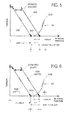
- FIG. 5 is a diagram illustrating inching control with manually adjusted, fixed inch/brake overlap.
- the vertical axis of the diagram represents an amount of torque provided by a transmission system and a braking system, respectively.
- the horizontal axis of the diagram represents a position or angle of an inch/brake pedal.
- a low transmission torque curve 58A illustrates an amount of clutch torque actuated according to the inch/brake pedal position. At a zero degrees inch/brake pedal position at the left-hand side of the diagram, the low transmission torque curve 58A is at a maximum value (e.g. the transmission is fully engaged). As the inch/brake pedal position moves from zero degrees through a first range of motion (illustrated as being from zero to approximately twelve degrees), the transmission torque value decreases from the maximum value to zero torque. At zero torque, the transmission control system becomes disengaged, such that the vehicle engine is unable to provide any acceleration to the vehicle.
- Brake torque curve 55 illustrates an amount of brake torque applied according to the inch/brake pedal position.
- the brake torque curve 55A is at a minimum value (e.g. the brakes are beginning to engage).
- the first braking position 55A is shown as occurring at approximately fourteen degrees, for illustrative purposes only.
- the brake torque value increases from the minimum brake torque value to a maximum brake torque value.
- the second braking position 55B is shown as occurring at approximately twenty two degrees, for illustrative purposes only.
- the transmission system becomes disengaged and the braking system becomes engaged.
- the vehicle may coast according to any inertia or gravitational forces acting on it, there being no transmission or brake torque being applied to the vehicle drive axle. For certain applications involving operating the vehicle on relatively flat surfaces, this may be acceptable or desirable performance. However, where the vehicle is being operated on an incline, this may result in inadvertent movement of the vehicle prior to or during inching operations.
- the torque curve may be manually shifted by a service technician, for example, to be fixed at a high transmission torque curve 58B.
- the high transmission torque curve 58B also illustrates an amount of clutch torque actuated according to the inch/brake pedal position. At a zero degrees inch/brake pedal position at the left-hand side of the diagram, the high transmission torque curve 58B is at a maximum value (e.g. the transmission is fully engaged). As the inch/brake pedal position moves from zero degrees through a first range of motion (illustrated as being from zero to approximately eighteen degrees), the transmission torque value decreases from the maximum value to zero torque.
- the transmission control system As discussed with respect to the low transmission torque curve 58A, when the high transmission torque curve 58B reaches zero torque the transmission control system also becomes disengaged, such that the engine is unable to provide any acceleration to the vehicle. After the manual adjustment of the transmission torque curve, however, an inch/brake overlap provides an operating condition where the transmission system and the braking system both provide torque to the drive axle. As a result, by the time the high transmission torque curve 58B reaches zero, the braking torque curve 55 has increased to a non-trivial amount that may be sufficient to provide a certain degree of hill holding capability for the vehicle.
- the fixed high transmission torque curve 58B will continue to apply the same inch/brake overlap region which results in excessive heating of the transmission and braking system, and may also affect inching control of the vehicle.
- the service technician in order to revise the inching control system back to the low transmission torque curve 58A, the service technician once must again work on the vehicle to manually adjust the inch/brake overlap.
- FIG. 6 is an example diagram illustrating inching control with dynamically adjustable inch/brake overlap.
- the vertical axis of the diagram represents an amount of torque provided by the transmission system 14 and the braking system 4 of FIG. 1 , respectively.
- the horizontal axis of the diagram represents a position or angle of an inch/brake pedal, such as inch/brake pedal 43 of FIG. 2A .
- a first transmission torque curve 60A illustrates an amount of clutch torque actuated associated with the fully released accelerator pedal position APP1 of FIG. 2B .
- the first transmission torque curve 60A may be understood as being operable provided the accelerator pedal 50 ( FIG. 2B ) is held or maintained at the fully released pedal position APP1.
- the first transmission torque curve 60A is at a maximum value.
- the transmission torque value decreases from the maximum value to zero torque.
- Brake torque curve 65 illustrates an amount of brake torque actuated according to the inch/brake pedal position. At a first braking position 65A, the brake torque curve 65 is at a minimum value. As the inch/brake pedal position moves from the first braking position 65A through a second range of motion including a second braking position 65B, the brake torque value increases from the minimum brake torque value to a maximum brake torque value.
- the transmission system 14 As the inch/brake pedal 43 ( FIG. 2A ) is moved from the first range of motion associated with the first transmission torque curve 60A to the second range of motion associated with the brake torque curve 65, the transmission system 14 ( FIG. 1 ) becomes disengaged and the braking system 4 ( FIG. 1 ) becomes engaged.
- the region between the first transmission torque curve 60A and the brake torque curve 65 as illustrated in FIG. 6 identifies inch/brake underlap. Inch/brake underlap is indicated when the input received from the accelerator pedal position sensor 212 ( FIG. 1 ) indicates zero vehicle acceleration, and wherein neither the transmission system 14 nor the braking system 4 are engaged.
- only one of the transmission system 14 or the braking system 4 is engaged when the inching control system 10 is outside of the inch/brake overlap region.
- the position of the inch/brake pedal 43 is between pedal position IBP1 and POP1, only the transmission system 14 is engaged.
- the position of the inch/brake pedal 43 is between pedal positions 65A and IBP2, and an inch/brake underlap condition exists, only the brake system 4 is engaged.
- the torque curve may be dynamically adjusted or shifted between the first transmission torque curve 60A and a second transmission torque curve 60B, according to a position of the accelerator pedal 50 ( FIG. 2B ).
- the second transmission torque curve 60B is associated with the fully pressed accelerator pedal position APP2 ( FIG. 2B ).
- the second transmission torque curve 60B may be understood as being operable provided the accelerator pedal 50 ( FIG. 2B ) is held or maintained at the fully pressed accelerator pedal position APP2.
- the second transmission torque curve 60B also illustrates an amount of clutch torque actuated according to the inch/brake pedal position.
- the second transmission torque curve 60B is at a maximum value.
- the transmission torque value decreases from the maximum value to zero torque.
- the inch/brake overlap region exists as a function of actuating both the brake pedal 43 and the accelerator pedal 50 at the same time. Simultaneously pressing the inch/brake pedal 43 and the accelerator pedal 50 causes the transmission driving torque to be available before the brake torque is released.
- An inch/brake overlap is illustrated as occurring between the brake torque curve 65 and the second transmission torque curve 60B.
- the inch/brake overlap may be understood to exist between the inch/brake pedal position 65A and the inch/brake pedal position POP2, wherein pedal position POP2 indicates that the inch/brake pedal 43 has been pressed further than indicated by pedal position 65A,
- the inch/brake overlap region provides an operating condition where the transmission system 14 and the braking system 4 both simultaneously provide torque to the drive axle 34 for the same position, or range of positions, of the inch/brake pedal 43.
- the inch/brake overlap region varies according to input received from the accelerator pedal position sensor 212 ( FIG. 1 ). In one embodiment, the inch/brake overlap region is largest when the input received from the accelerator pedal position sensor 212 indicates a request for maximum vehicle travel speed. On the other hand, the inch/brake overlap region may be smallest when the input received from the accelerator pedal position sensor 212 indicates a request for zero vehicle travel speed.
- FIG. 7 is a further example diagram illustrating inching control with dynamically adjustable inch/brake overlap.
- a motorized vehicle may comprise a transmission system, such as transmission system 14 ( FIG. 1 ), and an inch/brake device, such as inch/brake pedal 43 ( FIG. 2A ) configured to provide at least two ranges of motion.
- the first range of motion may include a position of the inch/brake pedal 43 between pedal positions 65A and 65B.
- a braking force of the motorized vehicle is provided in the first range of motion of the inch/brake pedal 43.
- the second range of motion may include a position of the inch/brake pedal 43 between pedal positions IBP1 and POP1 or POP2,
- An engagement force of the transmission system 14 is provided in the second range of motion of the inch/brake pedal 43.
- the motorized vehicle may further comprise an accelerator device, such as accelerator pedal 50 ( FIG. 2B ) configured to be moved between two or more positions.
- an accelerator device such as accelerator pedal 50 ( FIG. 2B ) configured to be moved between two or more positions.
- moving the accelerator pedal 50 from one position to another position causes an amount of overlap between the first and second ranges of motion of the inch/brake pedal 43 to vary.
- the inch/brake pedal 43 may be configured to simultaneously provide both the braking force of the motorized vehicle and the engagement force of the transmission system 14 when the first and second ranges of motion of the inch/brake pedal 43 overlap.
- FIG. 7 further illustrates an intermediate transmission torque curve 70A associated with an intermediate, or partially pressed position APP0 of the accelerator pedal 50.
- the intermediate transmission torque curve 70A overlaps with the brake torque curve 65, as identified by a first overlap region OV1.
- First overlap region OV1 provides for a reduced amount of transmission torque for a fixed or selected position of the inch/brake pedal 43, for example inch/brake pedal position POP1.
- Second transmission torque curve 70B is associated with the fully pressed position APP2 of the accelerator pedal 50.
- the second transmission torque curve 70B overlaps with the brake torque curve 65, as identified by a second overlap region OV2.
- the region identified by the second overlap region OV2 is larger than, and includes the region identified by, the first overlap region OV1.
- the engagement torque of the transmission system 14 varies as the amount of overlap varies, wherein the braking force of the motorized vehicle remains constant, for a single or select position of the inch/brake pedal 43.
- the transmission torque associated with the second transmission curve 70B is greater than the transmission torque associated with the intermediate torque curve 70A, for the same position POP1 of the inch/brake pedal 43.
- the accelerator pedal position may be made to vary, for example between accelerator pedal position APP0 and APP2, in order to vary an amount of transmission torque for the selected position of the inch/brake pedal.
- the operator may initially press the accelerator pedal 50 to position APP0 while simultaneously pressing the inch/brake pedal 43 to position POP1.
- the amount of braking force or braking torque associated with inch/brake pedal position POP1 may be sufficient to keep the vehicle from rolling down the hill.
- the braking torque may not be sufficient to hold the vehicle.
- the transmission torque associated with transmission torque curve 70A may not be sufficient to propel or accelerate the vehicle up the grade.
- inch/brake overlap region dynamically increases and results in an increase in transmission torque associated with the transmission torque curve 70B without increasing the engine speed. This is shown in FIG. 7 by the upward trending transmission torque change 75.
- the increase of transmission torque may therefore cause the vehicle to accelerate up the steep incline without first rolling in the opposite direction.
- the position of the accelerator pedal 50 may be varied to any position intermediate pedal positions APP0 and APP 2, and for that matter between APP1 and APP2 to incrementally vary the amount of inch/brake overlap and corresponding change in transmission torque.
- FIG. 8 is an example diagram illustrating inching control with dynamically adjustable inch/brake overlap, and the interaction of the accelerator pedal 50 ( FIG. 2B ) and the inch/brake pedal 43 ( FIG. 2A ).
- Inch/brake pedal position 42 ( FIG. 3 ) corresponds to brake torque curve 65.
- the brake torque curve 65 may correspond with the braking torque provided by a service brake.
- the relationship between a inch/brake pedal position 42 and the brake torque is plotted on the brake torque curve 65. As the inch/brake pedal 43 is pressed, a point is reached where brake torque begins 304.
- Transmission driving torque is used to move the vehicle. If the inch/brake pedal 43 is released at inch/brake position IBP1, it corresponds to a maximum transmission driving torque at point 350. As the inch/brake pedal 43 is pressed, the transmission driving torque begins to be reduced during speed control 100.
- the first inching transmission torque curve 80A associated with the released accelerator pedal position APP1 ( FIG. 2B ) is plotted against the inch/brake pedal position.
- Speed control 100 remains in effect until point 352.
- Point 352 may correspond to a partially pressed inch/brake pedal position which is less than inch/brake pedal position POP1.
- point 352 is associated with an inch/brake position of approximately ten degrees, whereas inch/brake position POP1 is approximately twelve degrees.
- the transmission driving torque of speed control 100 is a function of accelerator pedal position 44 ( FIG. 3 ), inch/brake pedal position 42, engine speed 30 ( FIG. 3 ), speed of the shaft 17 ( FIG. 4 ), the target vehicle travel speed, and the actual vehicle travel speed and direction 18 ( FIG. 3 ).
- the transmission driving torque will begin to increase at point 355 and follow the first inching transmission torque curve 80A upward and to the left to point 351.
- the inching control transitions back to speed control 100.
- brake torque begins to increase according to the brake torque curve 65. If the inch/brake pedal position 42 is then steadily decreased from a point on the brake torque curve 65 towards the partially pressed inch/brake pedal position POP2, the transmission driving torque will increase from point 356 to point 357 and follow the second inching torque curve 80B that was shifted by pressing the accelerator pedal 50.
- the amount of shift of the inching torque curve is proportional to an amount that the accelerator pedal 50 is pressed. At point 351, the inching control transitions back to speed control 100.
- the transmission driving torque is equal to zero before the brake torque begins to rise, then inch/brake underlap exists. If the transmission driving torque is greater than zero after the brake torque begins to rise, then inch/brake overlap exists. If the accelerator pedal 50 is pressed while inching control is in effect, then the first inching transmission torque curve 80A undergoes a dynamic shift to the right to the second inching transmission torque curve 80B. This has the affect of dynamically increasing the inch/brake overlap region. This is useful for starting on a grade, and helps prevent the vehicle rolling back down the hill during starting or inching.
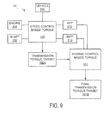
- FIG. 9 is an example block diagram illustrating a system or process 90 of determining transmission torque for an accelerator pedal based speed control system.
- Process 90 comprises several applications, including a speed control based torque application 100 and an inching control based torque application 101.
- Applications 100 and 101 may be implemented in software or hardware, and in one embodiment, operations performed by one or more of the applications 100 and 101 are performed by controller 40 of FIG. 1 .
- Speed control based torque application 100 determines transmission torque target 100A.
- Speed control based torque application 100 receives input from a number of different components or sensors to determine the transmission torque target 100A. Input may be received from one or more of the vehicle speed sensor 200, the engine speed sensor 204, the torque converter shaft speed sensor 202, the APP sensor 212, and the IBPP sensor 210 (see FIGS. 1 and 3 ).
- the transmission torque target 100A may be determined as a function of the input from one or more of the sensors 200, 202, 204, 210, 212.
- a target travel speed is first determined as a function of input from APP sensor 212 and IBPP sensor 210.
- the transmission torque target 100A is determined as a function of the target travel speed, and input from the vehicle speed sensor 200, engine speed sensor 204, and torque converter output shaft speed sensor 202.
- the inching control based torque application 101 determines final transmission torque target 101 B.
- final transmission torque target 101 B is determined as a function of the transmission torque target 100A, and input from the APP sensor 212 and the IBPP sensor 210.
- a look up table (LUT), such as LUT 48 of FIG. 1 , or a modified algorithm may be used in addition to, or in place of, the computations or functions described herein.
- the process 90 of determining transmission torque may be configured to dynamically increase transmission torque with braking torque, also known as inch/brake overlap, according to input received from the accelerator pedal 50 ( FIG. 2B ) and the inch/brake pedal 43 ( FIG. 2A ). Additional features of the one or more embodiments described herein are as follows:
- FIG. 10 illustrates an example method of operation 200 for providing inching control including a dynamically adjustable inch/brake overlap.
- an inch/brake device input e.g. inch/brake pedal position
- the inch/brake device input may indicate a braking position.
- a vehicle braking torque is reduced according to the inch/brake device input.
- an accelerator input (e.g. accelerator pedal position) is monitored.
- the accelerator input may indicate a first accelerator position and a second accelerator position.
- the level of transmission torque associated with the braking position may be zero when the accelerator input indicates the second accelerator position.
- an inch/brake overlap region is modified according to the accelerator position input, wherein the inch/brake overlap region is associated with simultaneous engagement of both a transmission system and a vehicle braking system.
- the transmission system may be initially engaged for different inch/brake device input values according to the accelerator input.
- a level of transmission torque associated with the braking position is increased when the accelerator input indicates the first accelerator position.
- a level of transmission torque associated with the braking position may be decreased when the accelerator input indicates the second accelerator position.
- a transmission torque curve associated with the transmission system may vary depending if the inch/brake device input is increasing or decreasing in value.
- the vehicle begins to move (operation 230).
- the transmission torque provided during the inching operation varies as a function of both the inch/brake device input and the accelerator input.
- FIG, 11 illustrates an example method of an inching control system 300 with dynamic inch/brake overlap.
- an inch/brake pedal position that exceeds an entry criteria e.g. minimum threshold value
- a speed input (e.g. accelerator pedal position) is monitored.
- the speed input may indicate a range from a first accelerator pedal position to a second accelerator pedal position.
- the speed input is multiplied by a gain factor K.
- This gain factor enables tuning of the inching control system 300 to accommodate combinations of different brakes and power trains providing the desired dynamic inch/brake overlap response.
- a clutch input (e.g. inch/brake pedal position) is monitored.
- the clutch input may indicate a transmission torque value or range of values.
- a change in clutch input value may indicate an increase or decrease in transmission torque.
- the change in clutch input value may further indicate an increase or decrease in braking torque.
- Clutch input is associated with a torque curve.
- the effective position of the inch/brake pedal is shifted according to the speed input and gain factor. This may result in a dynamic shift or modification of the torque curve.
- the dynamic shift may operate to increase the inch/brake overlap associated with simultaneous engagement of both a transmission system and a vehicle braking system as the speed input is increased (e.g. the accelerator pedal is pressed).
- the transmission system may be initially engaged for different inch/brake device input values according to the speed input.
- the transmission torque corresponding to the modified torque curve for the shifted inch/brake pedal position is looked up or otherwise determined. The corresponding transmission torque may then be commanded.
- the clutch input is monitored to determine if the system 300 should exit from inching control and return to speed control. In one embodiment, the system 300 exits from inching control when the inch/brake pedal has been released to a predetermined position or angle. If the clutch input remains greater than the predetermined value, then the system 300 returns to operation 320.
- one or more of the embodiments described herein may be configured to:
- the system and apparatus described above can use dedicated processor systems, micro-controllers, programmable logic devices, or microprocessors that perform some or all of the operations. Some of the operations described above may be implemented in software and other operations may be implemented in hardware. It is further understood that computer-readable medium having instructions stored thereon may be provided, wherein when the instructions are executed by at least one device, they are operable to perform some or all of the operations.
Landscapes
- Engineering & Computer Science (AREA)
- Transportation (AREA)
- Mechanical Engineering (AREA)
- Chemical & Material Sciences (AREA)
- Combustion & Propulsion (AREA)
- Automation & Control Theory (AREA)
- Regulating Braking Force (AREA)
- Transmission Of Braking Force In Braking Systems (AREA)
Abstract
Description
- Inching is the process by which an operator controls the slow forward or reverse travel movement of a motorized vehicle by the light application of clutch torque through the transmission. Certain industrial vehicles including material handling vehicles or fork lift trucks, include a dual-purpose inch/brake pedal. The inch/brake pedal operates to engage a vehicle braking system, and also to engage a vehicle transmission. Typically the braking system is fully engaged when the inch/brake pedal is fully depressed, whereas the vehicle transmission is fully engaged when the inch/brake pedal is fully released. Inching occurs in an intermediate range of motion of the inch/brake pedal when the vehicle transmission is only partially engaged. Many industrial vehicles further include an accelerator pedal which is used to control the engine speed. The accelerator pedal has no effect on the clutch torque until the vehicle transmission is engaged.
- The present state-of-the-art is to provide a fixed or manually adjustable amount of overlap of transmission drive torque to service brake torque according to the position of the inching/brake pedal alone or in combination with the service brake torque or brake pressure. This is known as inch/brake overlap. For vehicles that provide for adjustable overlap, a service technician manually adjusts the amount of overlap while the vehicle is being serviced. The amount of overlap is accordingly fixed at the adjusted amount during subsequent operation of the vehicle, until the overlap is once again manually adjusted by a service technician.
- As operating conditions of the vehicle change from one operating shift to the next, or indeed during the same operating shift, the fixed amount of inch/brake overlap is well suited for some operations and not for others. For example, if the inch/brake overlap is manually set at a low value, this works well when the vehicle is operating on level surfaces. The operator is able to control vehicle inching satisfactorily under normal conditions. However this same low value does not work well when the vehicle is operating on an inclined surface, in which case the vehicle will roll down the hill when the brake pressure decreases too low without sufficient transmission force to maintain a position of the vehicle on, or to move the vehicle up, the grade. During loading or unloading operations on an incline, unintended vehicle movement down the grade may cause damage to the load being moved, or to other equipment or vehicles located adjacent the load.
- If the inch/brake overlap is manually set at a high level for vehicle operations on an inclined surface, this will improve the hill holding operation of the vehicle. However, the high level of inch/brake overlap will result in an unnecessary buildup of heat in the transmission and braking systems as they work against each other. This results in more frequent and expensive vehicle maintenance requirements, and is undesirable when the primary application of the vehicle is on a level operating surface. Inching operation of the vehicle when the inch/brake overlap is high also affects the degree of fine controllability of the vehicle, tending to cause the vehicle to lurch or operate unevenly.
- The present invention addresses these and other problems.
- A motorized vehicle is disclosed herein, as comprising a transmission system and an inch/brake device configured to provide at least two ranges of motion. An engagement force of the transmission system is provided in a first range of motion of the inch/brake device, and a braking force of the motorized vehicle is provided in a second range of motion of the inch/brake device. An accelerator device is configured to move between two or more positions, wherein moving the accelerator device from one position to another position causes an amount of overlap between the first and second ranges of motion of the inch/brake device to vary.
- An inching control system is disclosed herein, as comprising an accelerator pedal position (APP) sensor and an inch/brake pedal position (IBPP) sensor. A vehicle processor is configured to selectively engage a transmission system or a vehicle braking system according to input received from the IBPP sensor. The vehicle processor is further configured to vary an amount of transmission engagement force associated with a single vehicle braking force value in an inch/brake overlap region of the inching control system according to input received from the APP sensor.
- A method is disclosed herein, comprising monitoring an inch/brake device input and reducing a vehicle braking torque according to the inch/brake device input. The method further comprises monitoring an accelerator input and modifying an inch/brake overlap region according to the accelerator position input. The inch/brake overlap region is associated with simultaneous engagement of both a vehicle transmission system and a vehicle braking system
- The foregoing and other objects, features and advantages of the invention will become more readily apparent from the following detailed description of a preferred embodiment of the invention which proceeds with reference to the accompanying drawings.
-
-
FIG. 1 illustrates a simplified block diagram of system comprising a controller configured to provide a dynamically adjustable inch/brake overlap. -
FIG. 2A illustrates a simplified example inch/brake pedal. -
FIG. 2B illustrates a simplified example accelerator pedal. -
FIG. 3 illustrates an example block diagram of a transmission control system for a power shift transmission. -
FIG. 4 illustrates a further block diagram of the power shift transmission ofFIG. 3 . -
FIG. 5 is a diagram illustrating inching control with a manually adjusted fixed inch/brake overlap. -
FIG. 6 is an example diagram illustrating inching control with dynamically adjustable inch/brake overlap. -
FIG. 7 is a further example diagram illustrating inching control with dynamically adjustable inch/brake overlap. -
FIG. 8 is an example diagram illustrating inching control with dynamically adjustable inch/brake overlap. -
FIG. 9 is an example block diagram illustrating a process of determining transmission torque for an accelerator pedal based speed control system. -
FIG. 10 illustrates an example method of operation for providing inching control including a dynamically adjustable inch/brake overlap. -
FIG. 11 illustrates an example method of an inching control system with dynamic inch/brake overlap. -
FIG. 1 illustrates a simplified block diagram of aninching control system 10 comprising acontroller 40 configured to provide a dynamically adjustable inch/brake overlap. The inching control system enhances inching control functionality by using acceleration pedal position (APP) to dynamically adjust or automatically vary the overlap of transmission driving torque with the service brake torque. Dynamically adjusting the relationship between transmission torque and brake torque provides the operator maximum controllability of vehicle positioning and inching operations in a variety of applications. - The
inching control system 10 includes anAPP sensor 212, and an inch/brake pedal position (IBPP)sensor 210. Thecontroller 40 may comprise a vehicle processor, wherein thecontroller 40 is configured to selectively engage atransmission control system 14 or avehicle braking system 4 according to input received from theIBPP sensor 210. Thecontroller 40 is further configured to vary an amount of transmission engagement force or transmission torque TT associated with a single vehicle braking force value in an inch/brake overlap region of theinching control system 10 according to input received from theAPP sensor 212. - In one embodiment, the
transmission control system 14 and thevehicle braking system 4 are simultaneously engaged within the inch/brake overlap region. This results in simultaneous application of the transmission torque TT and a braking torque BT to avehicle drive axle 34. Thedrive axle 34 may comprise two ormore drive wheels 39. The braking torque BT may be understood as operating in an opposite direction as the transmission torque TT, as the braking torque BT resists a rotation of thedrive axle 34 due to the rotational force of the transmission torque TT. -
FIG. 2A illustrates a simplified example inch/brake pedal 43, shown in multiple operating positions. The inch/brake pedal 43 is shown mounted to, or otherwise located on, a cowl oroperating platform 25 of a vehicle, however inch/brake pedal 43 may be located in any position or location within an operator compartment. In one embodiment, inch/brake pedal 43 pivots about an approximately horizontal axis to form varying angles or ranges of motion with respect to theoperating platform 25. - The inch/
brake pedal 43 illustrated inFIG. 2A is shown in solid lines at a fully released position IBP1. The inch/brake pedal 43 may include a return spring or other device that causes the inch/brake pedal 43 to remain or return to the released position IBP1 anytime that an operator removes their foot from, or ceases to apply a minimum amount of force against, the inch/brake pedal 43. At the fully released position IBP1, the inch/brake pedal 43 is associated with an input from the IBPP sensor 210 (FIG. 1 ) that corresponds to a full engagement of thetransmission control system 14. Various partially and fully depressed positions POP1, POP2 , IBP2 of the inch/brake pedal 43 are shown as dashed lines. One skilled in the art will appreciate that partially depressed positions POP1, POP2 represent only two of the many possible positions that the inch/brake pedal 43 may be located at, intermediate the fully released position IBP1 and the fully depressed position IBP2. - The fully depressed position IBP2 of the inch/
brake pedal 43 is associated with an input from theIBPP sensor 210 that corresponds to a full engagement of the braking system 4 (FIG. 1 ), wherein the transmission control system 14 (FIG. 1 ) is fully disengaged. One or more of the partially depressed positions POP1, POP2 correspond to a range of motion of the inch/brake pedal 43 that provides inch/brake overlap. -
FIG. 2B illustrates a simplifiedexample accelerator pedal 50, shown in multiple operating positions. Theaccelerator pedal 50 is shown mounted to, or otherwise located on, a cowl or operatingplatform 25 of a vehicle, howeveraccelerator pedal 50 may be located in any position or location within an operator compartment. In one embodiment,accelerator pedal 50 pivots about an approximately horizontal axis to form varying angles or ranges of motion with respect to the operatingplatform 25. - The
accelerator pedal 50 illustrated inFIG. 2B is shown in solid lines at a released position APP1. Theaccelerator pedal 50 may include a return spring or other device that causes theaccelerator pedal 50 to remain or return to the fully released position APP1 anytime that an operator removes their foot from, or ceases to apply a minimum amount of force against, theaccelerator pedal 50. At the fully released position APP1, theaccelerator pedal 50 is associated with an input from the APP sensor 212 (FIG. 1 ) that corresponds to a zero or minimum request for vehicle speed, or a minimum engine speed, depending on the type of vehicle transmission. - Various partially and fully depressed positions APP0, APP2 of the
accelerator pedal 50 are shown as dashed lines. One skilled in the art will appreciate that partially depressed position APP0 represents only one of the many possible positions that theaccelerator pedal 50 may be located at, intermediate the fully released position APP1 and the fully depressed position APP2. The partially depressed positions APP0 of theaccelerator pedal 50 is associated with an input from theAPP sensor 212 that corresponds to an intermediate request for vehicle speed, or an intermediate engine speed, depending on the type of vehicle transmission. - The fully depressed position APP2 of the
accelerator pedal 50 is associated with an input from theAPP sensor 212 that corresponds to a maximum request for vehicle speed, or a maximum engine speed, depending on the type of vehicle transmission. In one embodiment, theaccelerator pedal 50 provides speed-based accelerator pedal position functionality, wherein a different vehicle speed is associated with each position or angle of theaccelerator pedal 50, independent of the engine speed. - In some transmission control systems, the position of the accelerator pedal sets a target travel speed. Transmission torque is controlled in combination with engine rpm to deliver the target travel speed regardless of load or grade. The Transmission Control System illustrated in
FIGS. 1 and3 operates similarly as described inUS Patent No. 6,950,737 to Robert Lee Chess, filed October 20, 2003 and entitled "Transmission Control System", the specification of which is incorporated by reference in its entirety. - Inch/
brake pedal 43 andaccelerator pedal 50 may be understood to comprise one or more pedals, buttons, joysticks, toggles, switches, or any other operating control known in the art. Any reference to pressing, depressing or otherwise changing a location or position of thepedals pedals -
FIG. 3 illustrates an example block diagram of atransmission control system 14.Transmission control system 14 is connected to anengine 12 by ahydraulic torque converter 15. Anoutput shaft 38 of thetransmission control system 14 is connected to adrive axle 34 that driveswheels 39. In one example, thetransmission control system 14 is used in a fork lift truck. However, thetransmission control system 14 can also be used in other types of vehicles. - A Central Processing Unit (CPU) or
controller 40 controls the activation of a forward clutch pack (FWD) 54 and a reverse clutch pack (REV) 56 in thetransmission control system 14 according to different vehicle parameters. Acontrol valve 16 in thetransmission control system 14 controls fluid pressure that activates the twoclutch packs - The
controller 40 receives a vehicle speed and direction signal 18 from avehicle speed sensor 200 indicating the rotational speed and direction of thedrive axle 34. Aconverter speed signal 20 is generated from a torqueconverter speed sensor 202 and indicates the rotational speed for a shaft 17 (FIG. 4 ) of thetorque converter 15. Anengine speed signal 30 is generated from anengine speed sensor 204 and indicates how fast an output shaft 13 (FIG. 4 ) of theengine 12 is rotating. An enginegovernor control signal 32 controls the speed ofengine 12. Atransmission temperature signal 28 is generated from atemperature sensor 208 and indicates the temperature of the transmission fluid in thetorque converter 15 ortransmission control system 14. -
FIG. 4 illustrates a further block diagram of thetransmission control system 14 ofFIG. 3 . In one embodiment, thetransmission control system 14 comprises a powershift transmission. The inching control system ofFIG. 1 may operate with a single speed powershift transmission, a multi-speed powershift transmission, or any other combination of gears, for performing the braking and inching operations described herein. - The
torque converter 15 includes an impeller pump 214 and aturbine 216. Ashaft 13 extends from the impeller pump 214 and is coupled to the crankshaft ofengine 12.Shaft 17 extends from theturbine 216 and is coupled to the input oftransmission control system 14. Thetorque converter 15 continuously varies the ratio of the speed of theshaft 17 to the speed of theshaft 13 in accordance with the load on theshaft 17. - The
forward clutch 54 and the reverse clutch 56 each selectively engages and disengages theshaft 17 withshaft 38 through the forward gears 21 and reverse gears 23. The engaging force of theclutches oil chambers 54C and 56C, respectively. The oil pressures are controlled by thecontrol valve 16 which is controlled by the controller 40 (FIG. 3 ), Theclutches - When the clutch pressures are both zero, the
clutches shaft 38 from theshaft 17. When the clutch pressure for either of the clutch packs is at a maximum pressure, the corresponding clutch pack maximizes the engaging force (locking). When the clutch pack pressure is between zero and the maximum value, the corresponding clutch pack is partially engaged. The partially engaged condition is referred to as clutch pack slipping. A FWD-1signal 24 inFIG. 3 controls the oil pressure in theforward clutch 54. A REV-1signal 22 inFIG. 3 controls the oil pressure in thereverse clutch 56. A FWD-2signal 26 controls the oil pressure in the forward high clutch (not shown). - The
controller 40 receives a brake pedal position signal 42 from theIBPP sensor 210 on inch/brake pedal 43. An acceleratorpedal position signal 44 is received from theAPP sensor 212 onaccelerator pedal 50. The accelerator pedal position can alternatively refer to a throttle value, acceleration value, deceleration value, engine speed value, engine torque value, or a target vehicle travel speed value. A forward-reverse direction signal 46 is generated by adirection sensor 52 and indicates a forward or backward direction the vehicle operator selects for the vehicle. An internal orexternal memory 48 contains mapped parameters identifying clutch pack pressure values and other control parameters used for performing different braking operations. -
FIG. 5 is a diagram illustrating inching control with manually adjusted, fixed inch/brake overlap. The vertical axis of the diagram represents an amount of torque provided by a transmission system and a braking system, respectively. The horizontal axis of the diagram represents a position or angle of an inch/brake pedal. - A low
transmission torque curve 58A illustrates an amount of clutch torque actuated according to the inch/brake pedal position. At a zero degrees inch/brake pedal position at the left-hand side of the diagram, the lowtransmission torque curve 58A is at a maximum value (e.g. the transmission is fully engaged). As the inch/brake pedal position moves from zero degrees through a first range of motion (illustrated as being from zero to approximately twelve degrees), the transmission torque value decreases from the maximum value to zero torque. At zero torque, the transmission control system becomes disengaged, such that the vehicle engine is unable to provide any acceleration to the vehicle. -
Brake torque curve 55 illustrates an amount of brake torque applied according to the inch/brake pedal position. At afirst braking position 55A, thebrake torque curve 55A is at a minimum value (e.g. the brakes are beginning to engage). Thefirst braking position 55A is shown as occurring at approximately fourteen degrees, for illustrative purposes only. As the inch/brake pedal position moves from thefirst braking position 55A through a second range of motion including asecond braking position 55B, the brake torque value increases from the minimum brake torque value to a maximum brake torque value. Thesecond braking position 55B is shown as occurring at approximately twenty two degrees, for illustrative purposes only. - As the inch/brake pedal is moved from the first range of motion associated with the low
transmission torque curve 58A to the second range of motion associated with thebrake torque curve 55, the transmission system becomes disengaged and the braking system becomes engaged. There is no inch/brake overlap between the lowtransmission torque curve 58A and thebrake torque curve 55, rather this region is referred to as underlap. In the underlap region, the vehicle may coast according to any inertia or gravitational forces acting on it, there being no transmission or brake torque being applied to the vehicle drive axle. For certain applications involving operating the vehicle on relatively flat surfaces, this may be acceptable or desirable performance. However, where the vehicle is being operated on an incline, this may result in inadvertent movement of the vehicle prior to or during inching operations. - The torque curve may be manually shifted by a service technician, for example, to be fixed at a high
transmission torque curve 58B. The hightransmission torque curve 58B also illustrates an amount of clutch torque actuated according to the inch/brake pedal position. At a zero degrees inch/brake pedal position at the left-hand side of the diagram, the hightransmission torque curve 58B is at a maximum value (e.g. the transmission is fully engaged). As the inch/brake pedal position moves from zero degrees through a first range of motion (illustrated as being from zero to approximately eighteen degrees), the transmission torque value decreases from the maximum value to zero torque. - As discussed with respect to the low
transmission torque curve 58A, when the hightransmission torque curve 58B reaches zero torque the transmission control system also becomes disengaged, such that the engine is unable to provide any acceleration to the vehicle. After the manual adjustment of the transmission torque curve, however, an inch/brake overlap provides an operating condition where the transmission system and the braking system both provide torque to the drive axle. As a result, by the time the hightransmission torque curve 58B reaches zero, thebraking torque curve 55 has increased to a non-trivial amount that may be sufficient to provide a certain degree of hill holding capability for the vehicle. - If the vehicle is then once again operated on a flat surface, the fixed high
transmission torque curve 58B will continue to apply the same inch/brake overlap region which results in excessive heating of the transmission and braking system, and may also affect inching control of the vehicle. However, in order to revise the inching control system back to the lowtransmission torque curve 58A, the service technician once must again work on the vehicle to manually adjust the inch/brake overlap. -
FIG. 6 is an example diagram illustrating inching control with dynamically adjustable inch/brake overlap. The vertical axis of the diagram represents an amount of torque provided by thetransmission system 14 and thebraking system 4 ofFIG. 1 , respectively. The horizontal axis of the diagram represents a position or angle of an inch/brake pedal, such as inch/brake pedal 43 ofFIG. 2A . - A first
transmission torque curve 60A illustrates an amount of clutch torque actuated associated with the fully released accelerator pedal position APP1 ofFIG. 2B . The firsttransmission torque curve 60A may be understood as being operable provided the accelerator pedal 50 (FIG. 2B ) is held or maintained at the fully released pedal position APP1. At the fully released inch/brake pedal position IBP1 (FIG. 2A ) at the left-hand side of the diagram, the firsttransmission torque curve 60A is at a maximum value. As the inch/brake pedal position moves from the fully released pedal position IBP1 through a first range of motion including partially pressed pedal position POP1 (FIG. 2A ), the transmission torque value decreases from the maximum value to zero torque. -
Brake torque curve 65 illustrates an amount of brake torque actuated according to the inch/brake pedal position. At afirst braking position 65A, thebrake torque curve 65 is at a minimum value. As the inch/brake pedal position moves from thefirst braking position 65A through a second range of motion including asecond braking position 65B, the brake torque value increases from the minimum brake torque value to a maximum brake torque value. - As the inch/brake pedal 43 (
FIG. 2A ) is moved from the first range of motion associated with the firsttransmission torque curve 60A to the second range of motion associated with thebrake torque curve 65, the transmission system 14 (FIG. 1 ) becomes disengaged and the braking system 4 (FIG. 1 ) becomes engaged. The region between the firsttransmission torque curve 60A and thebrake torque curve 65 as illustrated inFIG. 6 identifies inch/brake underlap. Inch/brake underlap is indicated when the input received from the accelerator pedal position sensor 212 (FIG. 1 ) indicates zero vehicle acceleration, and wherein neither thetransmission system 14 nor thebraking system 4 are engaged. - In one embodiment, only one of the
transmission system 14 or thebraking system 4 is engaged when the inchingcontrol system 10 is outside of the inch/brake overlap region. For example, when the position of the inch/brake pedal 43 is between pedal position IBP1 and POP1, only thetransmission system 14 is engaged. When the position of the inch/brake pedal 43 is betweenpedal positions 65A and IBP2, and an inch/brake underlap condition exists, only thebrake system 4 is engaged. - The torque curve may be dynamically adjusted or shifted between the first
transmission torque curve 60A and a secondtransmission torque curve 60B, according to a position of the accelerator pedal 50 (FIG. 2B ). The secondtransmission torque curve 60B is associated with the fully pressed accelerator pedal position APP2 (FIG. 2B ). The secondtransmission torque curve 60B may be understood as being operable provided the accelerator pedal 50 (FIG. 2B ) is held or maintained at the fully pressed accelerator pedal position APP2. - The second
transmission torque curve 60B also illustrates an amount of clutch torque actuated according to the inch/brake pedal position. At the released inch/brake pedal position IBP1 at the left-hand side of the diagram, the secondtransmission torque curve 60B is at a maximum value. As the inch/brake pedal 43 moves from the released pedal position IBP1 through a first range of motion including partially pressed pedal position POP2 (FIG. 2A ), the transmission torque value decreases from the maximum value to zero torque. In the embodiment illustrated byFIG. 6 , the inch/brake overlap region exists as a function of actuating both thebrake pedal 43 and theaccelerator pedal 50 at the same time. Simultaneously pressing the inch/brake pedal 43 and theaccelerator pedal 50 causes the transmission driving torque to be available before the brake torque is released. - An inch/brake overlap is illustrated as occurring between the
brake torque curve 65 and the secondtransmission torque curve 60B. The inch/brake overlap may be understood to exist between the inch/brake pedal position 65A and the inch/brake pedal position POP2, wherein pedal position POP2 indicates that the inch/brake pedal 43 has been pressed further than indicated bypedal position 65A, The inch/brake overlap region provides an operating condition where thetransmission system 14 and thebraking system 4 both simultaneously provide torque to thedrive axle 34 for the same position, or range of positions, of the inch/brake pedal 43. - The inch/brake overlap region varies according to input received from the accelerator pedal position sensor 212 (
FIG. 1 ). In one embodiment, the inch/brake overlap region is largest when the input received from the acceleratorpedal position sensor 212 indicates a request for maximum vehicle travel speed. On the other hand, the inch/brake overlap region may be smallest when the input received from the acceleratorpedal position sensor 212 indicates a request for zero vehicle travel speed. -
FIG. 7 is a further example diagram illustrating inching control with dynamically adjustable inch/brake overlap. A motorized vehicle may comprise a transmission system, such as transmission system 14 (FIG. 1 ), and an inch/brake device, such as inch/brake pedal 43 (FIG. 2A ) configured to provide at least two ranges of motion. The first range of motion may include a position of the inch/brake pedal 43 betweenpedal positions brake pedal 43. The second range of motion may include a position of the inch/brake pedal 43 between pedal positions IBP1 and POP1 or POP2, An engagement force of thetransmission system 14 is provided in the second range of motion of the inch/brake pedal 43. - The motorized vehicle may further comprise an accelerator device, such as accelerator pedal 50 (
FIG. 2B ) configured to be moved between two or more positions. In one embodiment, moving theaccelerator pedal 50 from one position to another position causes an amount of overlap between the first and second ranges of motion of the inch/brake pedal 43 to vary. - The inch/
brake pedal 43 may be configured to simultaneously provide both the braking force of the motorized vehicle and the engagement force of thetransmission system 14 when the first and second ranges of motion of the inch/brake pedal 43 overlap. The overlap between the first and second ranges of motion of the inch/brake device exists when the position of theaccelerator pedal 50 indicates a request for non-zero acceleration. -
FIG. 7 further illustrates an intermediatetransmission torque curve 70A associated with an intermediate, or partially pressed position APP0 of theaccelerator pedal 50. The intermediatetransmission torque curve 70A overlaps with thebrake torque curve 65, as identified by a first overlap region OV1. First overlap region OV1 provides for a reduced amount of transmission torque for a fixed or selected position of the inch/brake pedal 43, for example inch/brake pedal position POP1. - Second
transmission torque curve 70B is associated with the fully pressed position APP2 of theaccelerator pedal 50. The secondtransmission torque curve 70B overlaps with thebrake torque curve 65, as identified by a second overlap region OV2. The region identified by the second overlap region OV2 is larger than, and includes the region identified by, the first overlap region OV1. The engagement torque of thetransmission system 14 varies as the amount of overlap varies, wherein the braking force of the motorized vehicle remains constant, for a single or select position of the inch/brake pedal 43. For example, the transmission torque associated with thesecond transmission curve 70B is greater than the transmission torque associated with theintermediate torque curve 70A, for the same position POP1 of the inch/brake pedal 43. - In one embodiment, the accelerator pedal position may be made to vary, for example between accelerator pedal position APP0 and APP2, in order to vary an amount of transmission torque for the selected position of the inch/brake pedal. By way of example, when the vehicle is being operated on an incline, the operator may initially press the
accelerator pedal 50 to position APP0 while simultaneously pressing the inch/brake pedal 43 to position POP1. Depending on the angle of slope or grade that the vehicle is operating on, the amount of braking force or braking torque associated with inch/brake pedal position POP1 may be sufficient to keep the vehicle from rolling down the hill. For steeper grades, the braking torque may not be sufficient to hold the vehicle. Similarly, the transmission torque associated withtransmission torque curve 70A may not be sufficient to propel or accelerate the vehicle up the grade. - By pressing the
accelerator pedal 50 to accelerator pedal position APP2, inch/brake overlap region dynamically increases and results in an increase in transmission torque associated with thetransmission torque curve 70B without increasing the engine speed. This is shown inFIG. 7 by the upward trendingtransmission torque change 75. The increase of transmission torque may therefore cause the vehicle to accelerate up the steep incline without first rolling in the opposite direction. The position of theaccelerator pedal 50 may be varied to any position intermediate pedal positions APP0 andAPP 2, and for that matter between APP1 and APP2 to incrementally vary the amount of inch/brake overlap and corresponding change in transmission torque. -
FIG. 8 is an example diagram illustrating inching control with dynamically adjustable inch/brake overlap, and the interaction of the accelerator pedal 50 (FIG. 2B ) and the inch/brake pedal 43 (FIG. 2A ). Inch/brake pedal position 42 (FIG. 3 ) corresponds to braketorque curve 65. Thebrake torque curve 65 may correspond with the braking torque provided by a service brake. The relationship between a inch/brake pedal position 42 and the brake torque is plotted on thebrake torque curve 65. As the inch/brake pedal 43 is pressed, a point is reached where brake torque begins 304. - Transmission driving torque is used to move the vehicle. If the inch/
brake pedal 43 is released at inch/brake position IBP1, it corresponds to a maximum transmission driving torque atpoint 350. As the inch/brake pedal 43 is pressed, the transmission driving torque begins to be reduced duringspeed control 100. The first inchingtransmission torque curve 80A associated with the released accelerator pedal position APP1 (FIG. 2B ) is plotted against the inch/brake pedal position. -
Speed control 100 remains in effect untilpoint 352.Point 352 may correspond to a partially pressed inch/brake pedal position which is less than inch/brake pedal position POP1. In one embodiment,point 352 is associated with an inch/brake position of approximately ten degrees, whereas inch/brake position POP1 is approximately twelve degrees. The transmission driving torque ofspeed control 100 is a function of accelerator pedal position 44 (FIG. 3 ), inch/brake pedal position 42, engine speed 30 (FIG. 3 ), speed of the shaft 17 (FIG. 4 ), the target vehicle travel speed, and the actual vehicle travel speed and direction 18 (FIG. 3 ). - At
point 352, if theaccelerator pedal 50 is at APP1 (FIG. 2B ), then the transmission driving torque drops to a lower level indicated bypoint 354. Then as the inch/brake pedal position 42 increases further to partially pressed inch/brake pedal position POP1, the transmission driving torque continues to drop to zero atpoint 355. Atpoint 355, inch/brake underlap exists. When the inch/brake pedal position 42 reachespoint 304, the brake torque begins to increase according tobrake torque curve 65. - If the inch/
brake pedal position 42 is then steadily decreased from a point on thebrake torque curve 65 towards the partially pressed inch/brake pedal position POP1, the transmission driving torque will begin to increase atpoint 355 and follow the first inchingtransmission torque curve 80A upward and to the left to point 351. Atpoint 351, the inching control transitions back tospeed control 100. - At
point 352, if theaccelerator pedal 50 is pressed, then the transmission driving torque drops to a lower level indicated bypoint 353 on the second inchingtorque curve 80B associated with accelerator pedal position APP2 (FIG. 2B ). Then as the inch/brake pedal position 42 increases further towards partially pressed inch/brake pedal position POP2, the transmission driving torque continues to drop along the second inchingtorque curve 80B to zero atpoint 356. Atpoint 356, inch/brake overlap exists. At this point, a vehicle will feel like it is driving against the service brakes during inch/brake overlap. - As the inch/
brake pedal position 42 continues to increase towards the fully pressed inch/brake pedal position IBP2, brake torque begins to increase according to thebrake torque curve 65. If the inch/brake pedal position 42 is then steadily decreased from a point on thebrake torque curve 65 towards the partially pressed inch/brake pedal position POP2, the transmission driving torque will increase frompoint 356 to point 357 and follow the second inchingtorque curve 80B that was shifted by pressing theaccelerator pedal 50. In one embodiment, the amount of shift of the inching torque curve is proportional to an amount that theaccelerator pedal 50 is pressed. Atpoint 351, the inching control transitions back tospeed control 100. - If the transmission driving torque is equal to zero before the brake torque begins to rise, then inch/brake underlap exists. If the transmission driving torque is greater than zero after the brake torque begins to rise, then inch/brake overlap exists. If the
accelerator pedal 50 is pressed while inching control is in effect, then the first inchingtransmission torque curve 80A undergoes a dynamic shift to the right to the second inchingtransmission torque curve 80B. This has the affect of dynamically increasing the inch/brake overlap region. This is useful for starting on a grade, and helps prevent the vehicle rolling back down the hill during starting or inching. -
FIG. 9 is an example block diagram illustrating a system orprocess 90 of determining transmission torque for an accelerator pedal based speed control system.Process 90 comprises several applications, including a speed control basedtorque application 100 and an inching control basedtorque application 101.Applications applications controller 40 ofFIG. 1 . - Speed control based
torque application 100 determinestransmission torque target 100A. Speed control basedtorque application 100 receives input from a number of different components or sensors to determine thetransmission torque target 100A. Input may be received from one or more of thevehicle speed sensor 200, theengine speed sensor 204, the torque convertershaft speed sensor 202, theAPP sensor 212, and the IBPP sensor 210 (seeFIGS. 1 and3 ). Thetransmission torque target 100A may be determined as a function of the input from one or more of thesensors - In one embodiment, a target travel speed is first determined as a function of input from
APP sensor 212 andIBPP sensor 210. Next, thetransmission torque target 100A is determined as a function of the target travel speed, and input from thevehicle speed sensor 200,engine speed sensor 204, and torque converter outputshaft speed sensor 202. - The inching control based torque application 101 (see also
FIG. 8 ) determines finaltransmission torque target 101 B. During an inching operation, finaltransmission torque target 101 B is determined as a function of thetransmission torque target 100A, and input from theAPP sensor 212 and theIBPP sensor 210. A look up table (LUT), such asLUT 48 ofFIG. 1 , or a modified algorithm may be used in addition to, or in place of, the computations or functions described herein. - The
process 90 of determining transmission torque may be configured to dynamically increase transmission torque with braking torque, also known as inch/brake overlap, according to input received from the accelerator pedal 50 (FIG. 2B ) and the inch/brake pedal 43 (FIG. 2A ). Additional features of the one or more embodiments described herein are as follows: - Brake pedal position schedules the transmission driving torque.
- Acceleration pedal position increases inching overlap function by shifting the inch/brake schedule of transmission driving torque to the right.
- Opposite clutches of the transmission system are slipped at low desired drive torque to provide smooth engagement of torque.
- The starting inch/brake overlap relationship may be adjusted manually or electrically, so that more or less transmission torque corresponds to a fixed level of braking torque.
-
FIG. 10 illustrates an example method ofoperation 200 for providing inching control including a dynamically adjustable inch/brake overlap. Atoperation 205, an inch/brake device input (e.g. inch/brake pedal position) is monitored. The inch/brake device input may indicate a braking position. Atoperation 210, a vehicle braking torque is reduced according to the inch/brake device input. - At
operation 215, an accelerator input (e.g. accelerator pedal position) is monitored. The accelerator input may indicate a first accelerator position and a second accelerator position. The level of transmission torque associated with the braking position may be zero when the accelerator input indicates the second accelerator position. - At
operation 220, an inch/brake overlap region is modified according to the accelerator position input, wherein the inch/brake overlap region is associated with simultaneous engagement of both a transmission system and a vehicle braking system. The transmission system may be initially engaged for different inch/brake device input values according to the accelerator input. - In one embodiment a level of transmission torque associated with the braking position is increased when the accelerator input indicates the first accelerator position. A level of transmission torque associated with the braking position may be decreased when the accelerator input indicates the second accelerator position. A transmission torque curve associated with the transmission system may vary depending if the inch/brake device input is increasing or decreasing in value.
- When the transmission torque associated with the engagement of the transmission system is greater than the vehicle braking torque, the vehicle begins to move (operation 230). In one embodiment, the transmission torque provided during the inching operation varies as a function of both the inch/brake device input and the accelerator input.
-
FIG, 11 illustrates an example method of an inchingcontrol system 300 with dynamic inch/brake overlap. Atoperation 305, an inch/brake pedal position that exceeds an entry criteria (e.g. minimum threshold value) initiates an inching control operation or functionality. - At
operation 310, a speed input (e.g. accelerator pedal position) is monitored. The speed input may indicate a range from a first accelerator pedal position to a second accelerator pedal position. - At
operation 320, the speed input is multiplied by a gain factor K. This gain factor enables tuning of the inchingcontrol system 300 to accommodate combinations of different brakes and power trains providing the desired dynamic inch/brake overlap response. - At
operation 330, a clutch input (e.g. inch/brake pedal position) is monitored. The clutch input may indicate a transmission torque value or range of values. A change in clutch input value may indicate an increase or decrease in transmission torque. The change in clutch input value may further indicate an increase or decrease in braking torque. Clutch input is associated with a torque curve. - At
operation 340, the effective position of the inch/brake pedal is shifted according to the speed input and gain factor. This may result in a dynamic shift or modification of the torque curve. The dynamic shift may operate to increase the inch/brake overlap associated with simultaneous engagement of both a transmission system and a vehicle braking system as the speed input is increased (e.g. the accelerator pedal is pressed). The transmission system may be initially engaged for different inch/brake device input values according to the speed input. - At
operation 350, the transmission torque corresponding to the modified torque curve for the shifted inch/brake pedal position is looked up or otherwise determined. The corresponding transmission torque may then be commanded. - At
operation 360, the clutch input is monitored to determine if thesystem 300 should exit from inching control and return to speed control. In one embodiment, thesystem 300 exits from inching control when the inch/brake pedal has been released to a predetermined position or angle. If the clutch input remains greater than the predetermined value, then thesystem 300 returns tooperation 320. - By providing a vehicle with dynamic control of how much inch/brake overlap is available for any operation or job function requiring fine position control (e.g. inching) of a vehicle, vehicle operation is improved. For example, one or more of the embodiments described herein may be configured to:
- Enable a vehicle to start moving up hill from a stop on a grade without rolling downhill.
- Reduce excessive overlap between transmission torque and braking torque, thereby reducing system heat, increasing fuel economy, and increasing service life of truck components.
- Provide for fine traction control of the truck for very small movements.
- Provide an intuitive method to dynamically change the amount of inch/brake overlap, thus reducing operator training and increasing productivity.
- The system and apparatus described above can use dedicated processor systems, micro-controllers, programmable logic devices, or microprocessors that perform some or all of the operations. Some of the operations described above may be implemented in software and other operations may be implemented in hardware. It is further understood that computer-readable medium having instructions stored thereon may be provided, wherein when the instructions are executed by at least one device, they are operable to perform some or all of the operations.
- Where specific numbers are provided, they are given as examples only and are not intended to limit the scope of the claims. The relationship between inputs and outputs of the various operations, computation, and methods described herein may be established by algorithms or by look up tables contained in processor memory.
- For the sake of convenience, the operations are described as various interconnected functional blocks or diagrams. This is not necessary, however, and there may be cases where these functional blocks or diagrams are equivalently aggregated into a single logic device, program or operation with unclear boundaries.
- Having described and illustrated the principles of the invention in a preferred embodiment thereof, it should be apparent that the invention may be modified in arrangement and detail without departing from such principles. We claim all modifications and variation coming within the spirit and scope of the following claims.
Claims (15)
- A motorized vehicle comprising:a transmission system;an inch/brake device configured to provide at least two ranges of motion, wherein an engagement force of the transmission system is provided in a first range of motion of the inch/brake device, and wherein a braking force of the motorized vehicle is provided in a second range of motion of the inch/brake device; andan accelerator device configured to be moved between two or more positions, wherein moving the accelerator device from one position to another position causes an amount of overlap between the first and second ranges of motion of the inch/brake device to vary.
- The motorized vehicle according to claim 1, wherein the inch/brake device is configured to simultaneously provide both the braking force of the motorized vehicle and the engagement force of the transmission system when the first and second ranges of motion of the inch/brake device overlap.
- The motorized vehicle according to claim 1 or 2, wherein there is no overlap between the first and second ranges of motion of the inch/brake device when the position of the accelerator device requests zero speed.
- The motorized vehicle according to claim 3, wherein there is an overlap between the first and second ranges of motion of the inch/brake device when the position of the accelerator device requests a non-zero speed.
- The motorized vehicle according to one of claims 1 to 4, wherein the engagement force of the transmission varies as the amount of overlap varies, and wherein the braking force of the motorized vehicle remains constant, for a single position of the inch/brake device.
- The motorized vehicle according to claims 5, wherein the engagement force of the transmission system varies without changing an engine speed.
- The motorized vehicle according to one of claims 1 to 6, wherein the amount of overlap between the first and second ranges of motion of the inch/brake device is largest when the position of the accelerator device is associated with a maximum vehicle speed.
- The motorized vehicle according to claim 7, wherein the amount of overlap between the first and second ranges of motion of the inch/brake device is smallest when the position of the accelerator device is associated with a zero vehicle speed.
- The motorized vehicle according to claim 7, wherein only one of the transmission system or the vehicle braking system is engaged when there is no overlap between the first and second ranges of motion of the inch/brake device.
- A method, comprising:monitoring an inch/brake device input;reducing a vehicle braking torque according to the inch/brake device input;monitoring an accelerator input; andmodifying an inch/brake overlap region according to the accelerator position input, wherein the inch/brake overlap region is associated with simultaneous engagement of both a vehicle transmission system and a vehicle braking system.
- The method according to claim 10, wherein the inch/brake device input indicates a braking position, and wherein the accelerator input indicates a first accelerator position and a second accelerator position, and wherein the method further comprises:increasing a level of transmission torque associated with the braking position when the accelerator input indicates the first accelerator position; anddecreasing a level of transmission torque associated with the braking position when the accelerator input indicates the second accelerator position, wherein the level of transmission torque is increased or decreased without changing an engine speed.
- The method according to claim 11, wherein the level of transmission torque associated with the braking position is zero when the accelerator input indicates the second accelerator position.
- The method according to claim 10, 11 or 12, further comprising:beginning an inching operation when a transmission torque associated with the engagement of the vehicle transmission system is greater than the vehicle braking torque.
- The method according to claim 13, wherein the transmission torque provided during the inching operation varies as a function of both the inch/brake device input and the accelerator input.
- The method according to one of claims 10 to 14, wherein the vehicle transmission system is initially engaged for different inch/brake device input values according to the accelerator input.
Applications Claiming Priority (1)
| Application Number | Priority Date | Filing Date | Title |
|---|---|---|---|
| US98909007P | 2007-11-19 | 2007-11-19 |
Publications (3)
| Publication Number | Publication Date |
|---|---|
| EP2060467A2 true EP2060467A2 (en) | 2009-05-20 |
| EP2060467A3 EP2060467A3 (en) | 2018-05-23 |
| EP2060467B1 EP2060467B1 (en) | 2019-10-23 |
Family
ID=40466903
Family Applications (1)
| Application Number | Title | Priority Date | Filing Date |
|---|---|---|---|
| EP08169353.3A Active EP2060467B1 (en) | 2007-11-19 | 2008-11-18 | Dynamically adjustable inch/brake overlap for vehicle transmission control |
Country Status (2)
| Country | Link |
|---|---|
| US (1) | US8775039B2 (en) |
| EP (1) | EP2060467B1 (en) |
Cited By (2)
| Publication number | Priority date | Publication date | Assignee | Title |
|---|---|---|---|---|
| FR2969561A1 (en) * | 2010-12-22 | 2012-06-29 | Peugeot Citroen Automobiles Sa | Method for controlling startup of hybrid vehicle, involves pressing pedal by pressure of foot, rotating wheels by driving force exerted by power train based on pressing of pedal, and limiting driving force of wheels temporarily |
| CN112534154A (en) * | 2018-05-25 | 2021-03-19 | 邦奇动力有限责任公司 | Vehicle powertrain and method for controlling a powertrain in a vehicle |
Families Citing this family (6)
| Publication number | Priority date | Publication date | Assignee | Title |
|---|---|---|---|---|
| US8028788B2 (en) * | 2009-02-19 | 2011-10-04 | Nmhg Oregon, Llc | Spring applied brake and drive axle assembly |
| US8893845B2 (en) * | 2009-02-19 | 2014-11-25 | Nmhg Oregon, Llc | Multi-stage brake pedal linkage |
| US20130184906A1 (en) * | 2012-01-18 | 2013-07-18 | Textron Inc. | Control System For A Vehicle On An Incline |
| US9188218B2 (en) | 2013-05-31 | 2015-11-17 | Gm Global Technology Operations, Llc | Methodology for controlling a hydraulic control system of a continuously variable transmission |
| US9120658B2 (en) * | 2013-12-27 | 2015-09-01 | Komatsu Ltd. | Forklift and control method of forklift |
| US12338606B2 (en) * | 2021-09-02 | 2025-06-24 | Caterpillar Inc. | Inching systems and methods |
Citations (1)
| Publication number | Priority date | Publication date | Assignee | Title |
|---|---|---|---|---|
| US6950737B2 (en) | 2002-06-12 | 2005-09-27 | Nacco Materials Handling Group, Inc. | Transmission control system |
Family Cites Families (73)
| Publication number | Priority date | Publication date | Assignee | Title |
|---|---|---|---|---|
| GB1050283A (en) | 1900-01-01 | |||
| GB717868A (en) | 1952-04-07 | 1954-11-03 | Gen Motors Corp | Improved variable-speed power transmission mechanism for motor vehicles |
| US2757552A (en) | 1948-12-30 | 1956-08-07 | Borg Warner | Hydraulic controls for transmissions |
| GB730576A (en) | 1951-05-01 | 1955-05-25 | Gen Tire & Rubber Co | Torque transmitting devices such as clutches or brakes |
| US2938403A (en) | 1954-10-14 | 1960-05-31 | Borg Warner | Control for transmission |
| GB807395A (en) | 1956-06-21 | 1959-01-14 | Gen Motors Corp | Improved control system for variable-speed power transmission mechanism for motor vehicles |
| US3053116A (en) | 1958-04-25 | 1962-09-11 | Gen Motors Corp | Transmission |
| US3096667A (en) | 1960-08-15 | 1963-07-09 | Caterpillar Tractor Co | Transmission system and hydraulic controls therefor |
| DE1178307B (en) | 1960-12-17 | 1964-09-17 | Zahnradfabrik Friedrichshafen | Hydrodynamic-mechanical transmission, especially for motor vehicles |
| US3167970A (en) | 1962-04-23 | 1965-02-02 | Borg Warner | Manual and automatic transmission |
| US3158037A (en) | 1962-10-12 | 1964-11-24 | Ford Motor Co | Control valve system |
| US3258984A (en) | 1963-12-31 | 1966-07-05 | Ford Motor Co | Ratio shift-point control system for a power transmission mechanism |
| US3442152A (en) | 1964-06-18 | 1969-05-06 | Gen Motors Corp | Transmission and controls |
| US3561293A (en) | 1967-12-22 | 1971-02-09 | Nissan Motor | Hydraulic control system for automatic transmission |
| US3692160A (en) | 1970-08-24 | 1972-09-19 | Twin Disc Inc | Fluid power control system for vehicles |
| US3688607A (en) | 1971-05-26 | 1972-09-05 | Gen Motors Corp | Transmission and control |
| JPS5214390B2 (en) | 1971-12-28 | 1977-04-21 | ||
| US3893552A (en) | 1973-10-05 | 1975-07-08 | Horton Mfg Co Inc | Clutch and brake with interlock valves |
| DE2716531C2 (en) | 1976-04-14 | 1982-10-28 | Twin Disc Inc., 53402 Racine, Wis. | Hydraulic control device for reversing gearboxes |
| US4104991A (en) | 1976-08-23 | 1978-08-08 | Ford Motor Company | Circuit for controlling the operability of one or more cylinders of a multicylinder internal combustion engine |
| US4129148A (en) | 1977-06-30 | 1978-12-12 | International Harvester Company | Clutch modulator |
| CA1118235A (en) | 1978-10-30 | 1982-02-16 | Albert A. Miller | Reatarding means for motor vehicles |
| DE3135055C2 (en) | 1981-09-04 | 1984-04-26 | Jörg Prof. Dipl.-Ing.(FH) 7072 Heubach Linser | Brake-clutch combination |
| US4574927A (en) | 1983-12-19 | 1986-03-11 | Clark Michigan Company | Forward and reverse clutch engagement parking brake |
| EP0292648B1 (en) | 1987-05-22 | 1992-08-19 | ALFRED TEVES GmbH | Brake installation with antilock and/or driving slip control as well as brake pressure modulator for such brake installation |
| JP2611239B2 (en) | 1987-07-16 | 1997-05-21 | トヨタ自動車株式会社 | Vehicle speed control device |
| JPH01240350A (en) | 1988-03-23 | 1989-09-25 | Kubota Ltd | vehicle braking system |
| JPH0295938A (en) * | 1988-09-30 | 1990-04-06 | Toyota Autom Loom Works Ltd | Inching control device for industrial vehicle |
| JPH037625A (en) | 1989-06-02 | 1991-01-14 | Mitsubishi Motors Corp | Automatic traveling controller for vehicle |
| JPH03292456A (en) | 1990-04-10 | 1991-12-24 | Toyota Motor Corp | Shift controlling method of automatic transmission for vehicle |
| US5048655A (en) | 1990-05-22 | 1991-09-17 | Deere & Company | Electric declutch mechanism for direct drive crawler |
| JP3031982B2 (en) | 1990-09-26 | 2000-04-10 | マツダ株式会社 | Vehicle control device |
| JP2756354B2 (en) | 1990-10-02 | 1998-05-25 | 本田技研工業株式会社 | Control device for automatic transmission for vehicles |
| JPH04325733A (en) | 1991-04-25 | 1992-11-16 | Fuji Heavy Ind Ltd | Engine control device for vehicle with automatic transmission |
| GB2262818B (en) | 1991-12-24 | 1995-06-21 | Ricardo International Plc | Oscillation reduction |
| JPH0634027A (en) | 1992-07-10 | 1994-02-08 | Nippondenso Co Ltd | Friction transmission with torque detecting function |
| JP2811523B2 (en) | 1993-02-26 | 1998-10-15 | 小松フォークリフト株式会社 | Industrial vehicle cargo handling and travel control device |
| DE4321413C2 (en) | 1993-06-26 | 1996-04-11 | Bosch Gmbh Robert | Method and device for controlling the drive power of a vehicle |
| US5568378A (en) | 1994-10-24 | 1996-10-22 | Fisher-Rosemount Systems, Inc. | Variable horizon predictor for controlling dead time dominant processes, multivariable interactive processes, and processes with time variant dynamics |
| US5651436A (en) | 1995-04-20 | 1997-07-29 | Midwest Brake Bond Company | Brake and clutch control system |
| DE19517888A1 (en) | 1995-05-16 | 1996-11-21 | Zahnradfabrik Friedrichshafen | Reversible gearbox switchable under load |
| US5868214A (en) | 1995-08-29 | 1999-02-09 | Cummins Engine Company, Inc. | Cruise control governor using optimal droop selection logic |
| FR2739064B1 (en) | 1995-09-22 | 1997-10-31 | Renault | METHOD FOR LIMITING THE TORQUE OF AN AUTOMATIC TRANSMISSION |
| US5901059A (en) | 1996-09-13 | 1999-05-04 | Honeywell Measurex Corp | Method and apparatus for controlling a process using adaptive prediction feedback |
| JP3596213B2 (en) | 1997-02-21 | 2004-12-02 | 日産自動車株式会社 | Engine control device |
| US6186029B1 (en) | 1997-07-09 | 2001-02-13 | Dana Corporation | Dual input transmission |
| JPH1178617A (en) | 1997-09-05 | 1999-03-23 | Nissan Motor Co Ltd | Integrated control system for engine and automatic transmission |
| JP3007625B1 (en) | 1998-12-10 | 2000-02-07 | 日本アンテナ株式会社 | Bidirectional amplifier with monitor terminal |
| JP3799903B2 (en) | 1999-02-24 | 2006-07-19 | 株式会社豊田自動織機 | Industrial vehicle parking brake device |
| JP2001116070A (en) | 1999-10-18 | 2001-04-27 | Toyota Autom Loom Works Ltd | Industrial vehicle braking control device |
| US6782961B1 (en) | 1999-10-18 | 2004-08-31 | Kabushiki Kaisha Toyoda Jidoshokki Seisakusho | Driving control apparatus for industrial vehicle |
| US6335609B1 (en) | 2000-05-09 | 2002-01-01 | Ford Global Technologies, Inc. | Method for reducing peak phase current and decreasing staring time for an internal combustion engine having an induction machine |
| US6424902B1 (en) | 2000-10-30 | 2002-07-23 | Caterpillar Inc. | Method and apparatus for operating a continuously variable transmission in the torque limited region near zero output speed |
| JP3441722B2 (en) | 2000-12-22 | 2003-09-02 | 株式会社資生堂 | Cosmetics |
| JP4060537B2 (en) | 2001-02-07 | 2008-03-12 | 株式会社エクセディ | Auxiliary brake system for vehicles |
| US6551212B2 (en) * | 2001-02-16 | 2003-04-22 | Caterpillar Inc | Decelerator system for a work machine |
| JP4092885B2 (en) * | 2001-03-29 | 2008-05-28 | 株式会社豊田自動織機 | Inching operation feeling adjustment device for industrial vehicles |
| JP2002367299A (en) | 2001-06-07 | 2002-12-20 | Sony Corp | Optical pickup feed mechanism and disk drive device |
| JP2003182408A (en) | 2001-12-21 | 2003-07-03 | Toyota Motor Corp | Control device for automatic transmission |
| US6910359B2 (en) | 2002-05-07 | 2005-06-28 | Hi-Tech Welding Services, Inc. | Die apparatus and method for high temperature forming of metal products |
| US7974760B2 (en) | 2003-10-20 | 2011-07-05 | Nmhg Oregon, Inc. | Advanced power-shift transmission control system |
| JP3830912B2 (en) * | 2003-03-17 | 2006-10-11 | 小松フォークリフト株式会社 | Industrial vehicle travel control device |
| SE526348C2 (en) | 2003-08-27 | 2005-08-30 | Volvo Lastvagnar Ab | Method and arrangement for controlling torque in a driveline of a land vehicle |
| US7146263B2 (en) | 2003-09-30 | 2006-12-05 | Caterpillar Inc | Predictive load management system |
| US6901324B2 (en) | 2003-09-30 | 2005-05-31 | Caterpillar Inc | System and method for predictive load management |
| US7563196B2 (en) | 2004-04-27 | 2009-07-21 | Denso Corporation | Controller for automatic transmission |
| JP4140567B2 (en) | 2004-07-14 | 2008-08-27 | 松下電器産業株式会社 | Object tracking device and object tracking method |
| US7006909B1 (en) | 2004-10-20 | 2006-02-28 | Detroit Diesel Corporation | Engine delay compensation |
| JP4869951B2 (en) | 2005-01-19 | 2012-02-08 | オリンパス株式会社 | Medical device data analyzer |
| CN101128563B (en) | 2005-02-28 | 2012-05-23 | 三菱化学株式会社 | Phosphor, its production method and its application |
| US20060293822A1 (en) | 2005-06-27 | 2006-12-28 | Freightliner Llc | Predictive control method and apparatus for vehicle automatic transmission |
| JP4609390B2 (en) * | 2005-09-30 | 2011-01-12 | 株式会社豊田自動織機 | Forklift travel control device |
| JP4134141B2 (en) | 2005-10-20 | 2008-08-13 | 株式会社ジェイワンホーム | Floor concrete level construction method and level indicator |
-
2008
- 2008-11-11 US US12/268,615 patent/US8775039B2/en active Active
- 2008-11-18 EP EP08169353.3A patent/EP2060467B1/en active Active
Patent Citations (1)
| Publication number | Priority date | Publication date | Assignee | Title |
|---|---|---|---|---|
| US6950737B2 (en) | 2002-06-12 | 2005-09-27 | Nacco Materials Handling Group, Inc. | Transmission control system |
Cited By (3)
| Publication number | Priority date | Publication date | Assignee | Title |
|---|---|---|---|---|
| FR2969561A1 (en) * | 2010-12-22 | 2012-06-29 | Peugeot Citroen Automobiles Sa | Method for controlling startup of hybrid vehicle, involves pressing pedal by pressure of foot, rotating wheels by driving force exerted by power train based on pressing of pedal, and limiting driving force of wheels temporarily |
| CN112534154A (en) * | 2018-05-25 | 2021-03-19 | 邦奇动力有限责任公司 | Vehicle powertrain and method for controlling a powertrain in a vehicle |
| CN112534154B (en) * | 2018-05-25 | 2022-10-14 | 邦奇动力Psa电子变速箱有限责任公司 | Vehicle powertrain and method for controlling a powertrain in a vehicle |
Also Published As
| Publication number | Publication date |
|---|---|
| US20090132134A1 (en) | 2009-05-21 |
| US8775039B2 (en) | 2014-07-08 |
| EP2060467A3 (en) | 2018-05-23 |
| EP2060467B1 (en) | 2019-10-23 |
Similar Documents
| Publication | Publication Date | Title |
|---|---|---|
| EP2060467B1 (en) | Dynamically adjustable inch/brake overlap for vehicle transmission control | |
| US5020645A (en) | Vehicle clutch control system | |
| US7860631B2 (en) | Engine speed control for a low power hydromechanical transmission | |
| EP1395457B1 (en) | A method for reversing the driving direction | |
| JP2004076934A (en) | Electronically controlled transmission for high-speed vehicles | |
| JPH0310825B2 (en) | ||
| JPH04278842A (en) | Shift control method for automatic transmission and its cruise control operation mode | |
| EP1303422A1 (en) | Calculation of automated friction clutch urge torque on grades | |
| US9771077B2 (en) | Vehicle control system | |
| KR102565356B1 (en) | Regenerative braking control method of hybrid vehicle | |
| EP0239416A2 (en) | Control apparatus for automobile clutch | |
| US7517300B2 (en) | Retarding system implementing torque converter lockup | |
| US6227999B1 (en) | Method and apparatus for operating a clutch in an automated mechanical transmission | |
| JP5185954B2 (en) | How to operate an automatic or semi-automatic transmission of a large vehicle in idling mode | |
| JP5310597B2 (en) | Continuously variable transmission | |
| US6878095B2 (en) | Automatic-clutch control system of automatic clutch type transmission | |
| CN107539316B (en) | Method for operating a drive train of a motor vehicle | |
| EP1606529B1 (en) | System and method for controlling engagement of a clutch | |
| JP5150497B2 (en) | Method for driving an automatic or semi-automatic manual transmission for heavy vehicles in idling mode | |
| KR100384007B1 (en) | Shift controlling device and methode for automatic transmission of vehicle | |
| WO1998046909A2 (en) | Method and apparatus for operating a clutch in an automated mechanical transmission | |
| JP4766581B2 (en) | Vehicle speed control device | |
| JP4113997B2 (en) | Industrial vehicle inching control device | |
| KR101966536B1 (en) | Method for controlling reverse driving of continuously variable transmission | |
| JP2008101680A (en) | Shift control device for vehicle |
Legal Events
| Date | Code | Title | Description |
|---|---|---|---|
| PUAI | Public reference made under article 153(3) epc to a published international application that has entered the european phase |
Free format text: ORIGINAL CODE: 0009012 |
|
| AK | Designated contracting states |
Kind code of ref document: A2 Designated state(s): AT BE BG CH CY CZ DE DK EE ES FI FR GB GR HR HU IE IS IT LI LT LU LV MC MT NL NO PL PT RO SE SI SK TR |
|
| AX | Request for extension of the european patent |
Extension state: AL BA MK RS |
|
| RAP1 | Party data changed (applicant data changed or rights of an application transferred) |
Owner name: NACCO MATERIALS HANDLING GROUP, INC. |
|
| RAP1 | Party data changed (applicant data changed or rights of an application transferred) |
Owner name: HYSTER-YALE GROUP, INC. |
|
| PUAL | Search report despatched |
Free format text: ORIGINAL CODE: 0009013 |
|
| AK | Designated contracting states |
Kind code of ref document: A3 Designated state(s): AT BE BG CH CY CZ DE DK EE ES FI FR GB GR HR HU IE IS IT LI LT LU LV MC MT NL NO PL PT RO SE SI SK TR |
|
| AX | Request for extension of the european patent |
Extension state: AL BA MK RS |
|
| RIC1 | Information provided on ipc code assigned before grant |
Ipc: B60W 50/08 20060101ALI20180417BHEP Ipc: B60W 10/02 20060101ALN20180417BHEP Ipc: B60W 10/18 20060101ALN20180417BHEP Ipc: B60W 30/18 20060101AFI20180417BHEP |
|
| STAA | Information on the status of an ep patent application or granted ep patent |
Free format text: STATUS: REQUEST FOR EXAMINATION WAS MADE |
|
| 17P | Request for examination filed |
Effective date: 20181122 |
|
| RBV | Designated contracting states (corrected) |
Designated state(s): AT BE BG CH CY CZ DE DK EE ES FI FR GB GR HR HU IE IS IT LI LT LU LV MC MT NL NO PL PT RO SE SI SK TR |
|
| AKX | Designation fees paid |
Designated state(s): AT BE BG CH CY CZ DE DK EE ES FI FR GB GR HR HU IE IS IT LI LT LU LV MC MT NL NO PL PT RO SE SI SK TR |
|
| AXX | Extension fees paid |
Extension state: AL Extension state: RS Extension state: BA Extension state: MK |
|
| RIC1 | Information provided on ipc code assigned before grant |
Ipc: B60W 30/18 20120101AFI20190529BHEP Ipc: B60W 10/02 20060101ALN20190529BHEP Ipc: B60W 10/18 20120101ALN20190529BHEP Ipc: B60W 50/08 20120101ALI20190529BHEP |
|
| GRAP | Despatch of communication of intention to grant a patent |
Free format text: ORIGINAL CODE: EPIDOSNIGR1 |
|
| STAA | Information on the status of an ep patent application or granted ep patent |
Free format text: STATUS: GRANT OF PATENT IS INTENDED |
|
| RIC1 | Information provided on ipc code assigned before grant |
Ipc: B60W 30/18 20120101AFI20190531BHEP Ipc: B60W 50/08 20120101ALI20190531BHEP Ipc: B60W 10/02 20060101ALN20190531BHEP Ipc: B60W 10/18 20120101ALN20190531BHEP |
|
| RIC1 | Information provided on ipc code assigned before grant |
Ipc: B60W 30/18 20120101AFI20190613BHEP Ipc: B60W 50/08 20120101ALI20190613BHEP Ipc: B60W 10/18 20120101ALN20190613BHEP Ipc: B60W 10/02 20060101ALN20190613BHEP |
|
| INTG | Intention to grant announced |
Effective date: 20190710 |
|
| GRAS | Grant fee paid |
Free format text: ORIGINAL CODE: EPIDOSNIGR3 |
|
| GRAA | (expected) grant |
Free format text: ORIGINAL CODE: 0009210 |
|
| STAA | Information on the status of an ep patent application or granted ep patent |
Free format text: STATUS: THE PATENT HAS BEEN GRANTED |
|
| AK | Designated contracting states |
Kind code of ref document: B1 Designated state(s): AT BE BG CH CY CZ DE DK EE ES FI FR GB GR HR HU IE IS IT LI LT LU LV MC MT NL NO PL PT RO SE SI SK TR |
|
| REG | Reference to a national code |
Ref country code: GB Ref legal event code: FG4D |
|
| REG | Reference to a national code |
Ref country code: CH Ref legal event code: EP |
|
| REG | Reference to a national code |
Ref country code: IE Ref legal event code: FG4D |
|
| REG | Reference to a national code |
Ref country code: DE Ref legal event code: R096 Ref document number: 602008061465 Country of ref document: DE |
|
| REG | Reference to a national code |
Ref country code: AT Ref legal event code: REF Ref document number: 1193309 Country of ref document: AT Kind code of ref document: T Effective date: 20191115 |
|
| REG | Reference to a national code |
Ref country code: NL Ref legal event code: MP Effective date: 20191023 |
|
| REG | Reference to a national code |
Ref country code: LT Ref legal event code: MG4D |
|
| PG25 | Lapsed in a contracting state [announced via postgrant information from national office to epo] |
Ref country code: LT Free format text: LAPSE BECAUSE OF FAILURE TO SUBMIT A TRANSLATION OF THE DESCRIPTION OR TO PAY THE FEE WITHIN THE PRESCRIBED TIME-LIMIT Effective date: 20191023 Ref country code: NO Free format text: LAPSE BECAUSE OF FAILURE TO SUBMIT A TRANSLATION OF THE DESCRIPTION OR TO PAY THE FEE WITHIN THE PRESCRIBED TIME-LIMIT Effective date: 20200123 Ref country code: GR Free format text: LAPSE BECAUSE OF FAILURE TO SUBMIT A TRANSLATION OF THE DESCRIPTION OR TO PAY THE FEE WITHIN THE PRESCRIBED TIME-LIMIT Effective date: 20200124 Ref country code: PL Free format text: LAPSE BECAUSE OF FAILURE TO SUBMIT A TRANSLATION OF THE DESCRIPTION OR TO PAY THE FEE WITHIN THE PRESCRIBED TIME-LIMIT Effective date: 20191023 Ref country code: LV Free format text: LAPSE BECAUSE OF FAILURE TO SUBMIT A TRANSLATION OF THE DESCRIPTION OR TO PAY THE FEE WITHIN THE PRESCRIBED TIME-LIMIT Effective date: 20191023 Ref country code: FI Free format text: LAPSE BECAUSE OF FAILURE TO SUBMIT A TRANSLATION OF THE DESCRIPTION OR TO PAY THE FEE WITHIN THE PRESCRIBED TIME-LIMIT Effective date: 20191023 Ref country code: PT Free format text: LAPSE BECAUSE OF FAILURE TO SUBMIT A TRANSLATION OF THE DESCRIPTION OR TO PAY THE FEE WITHIN THE PRESCRIBED TIME-LIMIT Effective date: 20200224 Ref country code: BG Free format text: LAPSE BECAUSE OF FAILURE TO SUBMIT A TRANSLATION OF THE DESCRIPTION OR TO PAY THE FEE WITHIN THE PRESCRIBED TIME-LIMIT Effective date: 20200123 Ref country code: SE Free format text: LAPSE BECAUSE OF FAILURE TO SUBMIT A TRANSLATION OF THE DESCRIPTION OR TO PAY THE FEE WITHIN THE PRESCRIBED TIME-LIMIT Effective date: 20191023 Ref country code: ES Free format text: LAPSE BECAUSE OF FAILURE TO SUBMIT A TRANSLATION OF THE DESCRIPTION OR TO PAY THE FEE WITHIN THE PRESCRIBED TIME-LIMIT Effective date: 20191023 Ref country code: NL Free format text: LAPSE BECAUSE OF FAILURE TO SUBMIT A TRANSLATION OF THE DESCRIPTION OR TO PAY THE FEE WITHIN THE PRESCRIBED TIME-LIMIT Effective date: 20191023 |
|
| PG25 | Lapsed in a contracting state [announced via postgrant information from national office to epo] |
Ref country code: HR Free format text: LAPSE BECAUSE OF FAILURE TO SUBMIT A TRANSLATION OF THE DESCRIPTION OR TO PAY THE FEE WITHIN THE PRESCRIBED TIME-LIMIT Effective date: 20191023 Ref country code: IS Free format text: LAPSE BECAUSE OF FAILURE TO SUBMIT A TRANSLATION OF THE DESCRIPTION OR TO PAY THE FEE WITHIN THE PRESCRIBED TIME-LIMIT Effective date: 20200224 |
|
| REG | Reference to a national code |
Ref country code: CH Ref legal event code: PL |
|
| REG | Reference to a national code |
Ref country code: DE Ref legal event code: R097 Ref document number: 602008061465 Country of ref document: DE |
|
| PG2D | Information on lapse in contracting state deleted |
Ref country code: IS |
|
| PG25 | Lapsed in a contracting state [announced via postgrant information from national office to epo] |
Ref country code: LU Free format text: LAPSE BECAUSE OF NON-PAYMENT OF DUE FEES Effective date: 20191118 Ref country code: RO Free format text: LAPSE BECAUSE OF FAILURE TO SUBMIT A TRANSLATION OF THE DESCRIPTION OR TO PAY THE FEE WITHIN THE PRESCRIBED TIME-LIMIT Effective date: 20191023 Ref country code: CZ Free format text: LAPSE BECAUSE OF FAILURE TO SUBMIT A TRANSLATION OF THE DESCRIPTION OR TO PAY THE FEE WITHIN THE PRESCRIBED TIME-LIMIT Effective date: 20191023 Ref country code: CH Free format text: LAPSE BECAUSE OF NON-PAYMENT OF DUE FEES Effective date: 20191130 Ref country code: EE Free format text: LAPSE BECAUSE OF FAILURE TO SUBMIT A TRANSLATION OF THE DESCRIPTION OR TO PAY THE FEE WITHIN THE PRESCRIBED TIME-LIMIT Effective date: 20191023 Ref country code: DK Free format text: LAPSE BECAUSE OF FAILURE TO SUBMIT A TRANSLATION OF THE DESCRIPTION OR TO PAY THE FEE WITHIN THE PRESCRIBED TIME-LIMIT Effective date: 20191023 Ref country code: LI Free format text: LAPSE BECAUSE OF NON-PAYMENT OF DUE FEES Effective date: 20191130 Ref country code: MC Free format text: LAPSE BECAUSE OF FAILURE TO SUBMIT A TRANSLATION OF THE DESCRIPTION OR TO PAY THE FEE WITHIN THE PRESCRIBED TIME-LIMIT Effective date: 20191023 Ref country code: IS Free format text: LAPSE BECAUSE OF FAILURE TO SUBMIT A TRANSLATION OF THE DESCRIPTION OR TO PAY THE FEE WITHIN THE PRESCRIBED TIME-LIMIT Effective date: 20200223 |
|
| REG | Reference to a national code |
Ref country code: AT Ref legal event code: MK05 Ref document number: 1193309 Country of ref document: AT Kind code of ref document: T Effective date: 20191023 |
|
| REG | Reference to a national code |
Ref country code: BE Ref legal event code: MM Effective date: 20191130 |
|
| PLBE | No opposition filed within time limit |
Free format text: ORIGINAL CODE: 0009261 |
|
| STAA | Information on the status of an ep patent application or granted ep patent |
Free format text: STATUS: NO OPPOSITION FILED WITHIN TIME LIMIT |
|
| PG25 | Lapsed in a contracting state [announced via postgrant information from national office to epo] |
Ref country code: SK Free format text: LAPSE BECAUSE OF FAILURE TO SUBMIT A TRANSLATION OF THE DESCRIPTION OR TO PAY THE FEE WITHIN THE PRESCRIBED TIME-LIMIT Effective date: 20191023 |
|
| 26N | No opposition filed |
Effective date: 20200724 |
|
| PG25 | Lapsed in a contracting state [announced via postgrant information from national office to epo] |
Ref country code: IE Free format text: LAPSE BECAUSE OF NON-PAYMENT OF DUE FEES Effective date: 20191118 |
|
| PG25 | Lapsed in a contracting state [announced via postgrant information from national office to epo] |
Ref country code: AT Free format text: LAPSE BECAUSE OF FAILURE TO SUBMIT A TRANSLATION OF THE DESCRIPTION OR TO PAY THE FEE WITHIN THE PRESCRIBED TIME-LIMIT Effective date: 20191023 Ref country code: BE Free format text: LAPSE BECAUSE OF NON-PAYMENT OF DUE FEES Effective date: 20191130 Ref country code: SI Free format text: LAPSE BECAUSE OF FAILURE TO SUBMIT A TRANSLATION OF THE DESCRIPTION OR TO PAY THE FEE WITHIN THE PRESCRIBED TIME-LIMIT Effective date: 20191023 |
|
| PG25 | Lapsed in a contracting state [announced via postgrant information from national office to epo] |
Ref country code: CY Free format text: LAPSE BECAUSE OF FAILURE TO SUBMIT A TRANSLATION OF THE DESCRIPTION OR TO PAY THE FEE WITHIN THE PRESCRIBED TIME-LIMIT Effective date: 20191023 |
|
| PG25 | Lapsed in a contracting state [announced via postgrant information from national office to epo] |
Ref country code: HU Free format text: LAPSE BECAUSE OF FAILURE TO SUBMIT A TRANSLATION OF THE DESCRIPTION OR TO PAY THE FEE WITHIN THE PRESCRIBED TIME-LIMIT; INVALID AB INITIO Effective date: 20081118 Ref country code: MT Free format text: LAPSE BECAUSE OF FAILURE TO SUBMIT A TRANSLATION OF THE DESCRIPTION OR TO PAY THE FEE WITHIN THE PRESCRIBED TIME-LIMIT Effective date: 20191023 |
|
| PG25 | Lapsed in a contracting state [announced via postgrant information from national office to epo] |
Ref country code: TR Free format text: LAPSE BECAUSE OF FAILURE TO SUBMIT A TRANSLATION OF THE DESCRIPTION OR TO PAY THE FEE WITHIN THE PRESCRIBED TIME-LIMIT Effective date: 20191023 |
|
| PGFP | Annual fee paid to national office [announced via postgrant information from national office to epo] |
Ref country code: FR Payment date: 20241008 Year of fee payment: 17 |
|
| PGFP | Annual fee paid to national office [announced via postgrant information from national office to epo] |
Ref country code: DE Payment date: 20251021 Year of fee payment: 18 |
|
| PGFP | Annual fee paid to national office [announced via postgrant information from national office to epo] |
Ref country code: GB Payment date: 20251114 Year of fee payment: 18 |
|
| PGFP | Annual fee paid to national office [announced via postgrant information from national office to epo] |
Ref country code: IT Payment date: 20251014 Year of fee payment: 18 |