EP2059056A2 - Optical system and projection display device - Google Patents
Optical system and projection display device Download PDFInfo
- Publication number
- EP2059056A2 EP2059056A2 EP08019524A EP08019524A EP2059056A2 EP 2059056 A2 EP2059056 A2 EP 2059056A2 EP 08019524 A EP08019524 A EP 08019524A EP 08019524 A EP08019524 A EP 08019524A EP 2059056 A2 EP2059056 A2 EP 2059056A2
- Authority
- EP
- European Patent Office
- Prior art keywords
- primary color
- light
- signals
- image
- composite light
- Prior art date
- Legal status (The legal status is an assumption and is not a legal conclusion. Google has not performed a legal analysis and makes no representation as to the accuracy of the status listed.)
- Granted
Links
Images





Classifications
-
- H—ELECTRICITY
- H04—ELECTRIC COMMUNICATION TECHNIQUE
- H04N—PICTORIAL COMMUNICATION, e.g. TELEVISION
- H04N9/00—Details of colour television systems
- H04N9/12—Picture reproducers
- H04N9/31—Projection devices for colour picture display, e.g. using electronic spatial light modulators [ESLM]
- H04N9/3102—Projection devices for colour picture display, e.g. using electronic spatial light modulators [ESLM] using two-dimensional electronic spatial light modulators
- H04N9/312—Driving therefor
- H04N9/3126—Driving therefor for spatial light modulators in series
-
- G—PHYSICS
- G03—PHOTOGRAPHY; CINEMATOGRAPHY; ANALOGOUS TECHNIQUES USING WAVES OTHER THAN OPTICAL WAVES; ELECTROGRAPHY; HOLOGRAPHY
- G03B—APPARATUS OR ARRANGEMENTS FOR TAKING PHOTOGRAPHS OR FOR PROJECTING OR VIEWING THEM; APPARATUS OR ARRANGEMENTS EMPLOYING ANALOGOUS TECHNIQUES USING WAVES OTHER THAN OPTICAL WAVES; ACCESSORIES THEREFOR
- G03B21/00—Projectors or projection-type viewers; Accessories therefor
- G03B21/005—Projectors using an electronic spatial light modulator but not peculiar thereto
-
- G—PHYSICS
- G03—PHOTOGRAPHY; CINEMATOGRAPHY; ANALOGOUS TECHNIQUES USING WAVES OTHER THAN OPTICAL WAVES; ELECTROGRAPHY; HOLOGRAPHY
- G03B—APPARATUS OR ARRANGEMENTS FOR TAKING PHOTOGRAPHS OR FOR PROJECTING OR VIEWING THEM; APPARATUS OR ARRANGEMENTS EMPLOYING ANALOGOUS TECHNIQUES USING WAVES OTHER THAN OPTICAL WAVES; ACCESSORIES THEREFOR
- G03B21/00—Projectors or projection-type viewers; Accessories therefor
- G03B21/14—Details
- G03B21/26—Projecting separately subsidiary matter simultaneously with main image
-
- H—ELECTRICITY
- H04—ELECTRIC COMMUNICATION TECHNIQUE
- H04N—PICTORIAL COMMUNICATION, e.g. TELEVISION
- H04N13/00—Stereoscopic video systems; Multi-view video systems; Details thereof
- H04N13/30—Image reproducers
- H04N13/324—Colour aspects
-
- H—ELECTRICITY
- H04—ELECTRIC COMMUNICATION TECHNIQUE
- H04N—PICTORIAL COMMUNICATION, e.g. TELEVISION
- H04N13/00—Stereoscopic video systems; Multi-view video systems; Details thereof
- H04N13/30—Image reproducers
- H04N13/332—Displays for viewing with the aid of special glasses or head-mounted displays [HMD]
- H04N13/334—Displays for viewing with the aid of special glasses or head-mounted displays [HMD] using spectral multiplexing
-
- H—ELECTRICITY
- H04—ELECTRIC COMMUNICATION TECHNIQUE
- H04N—PICTORIAL COMMUNICATION, e.g. TELEVISION
- H04N13/00—Stereoscopic video systems; Multi-view video systems; Details thereof
- H04N13/30—Image reproducers
- H04N13/332—Displays for viewing with the aid of special glasses or head-mounted displays [HMD]
- H04N13/337—Displays for viewing with the aid of special glasses or head-mounted displays [HMD] using polarisation multiplexing
-
- H—ELECTRICITY
- H04—ELECTRIC COMMUNICATION TECHNIQUE
- H04N—PICTORIAL COMMUNICATION, e.g. TELEVISION
- H04N13/00—Stereoscopic video systems; Multi-view video systems; Details thereof
- H04N13/30—Image reproducers
- H04N13/363—Image reproducers using image projection screens
-
- H—ELECTRICITY
- H04—ELECTRIC COMMUNICATION TECHNIQUE
- H04N—PICTORIAL COMMUNICATION, e.g. TELEVISION
- H04N9/00—Details of colour television systems
- H04N9/12—Picture reproducers
- H04N9/31—Projection devices for colour picture display, e.g. using electronic spatial light modulators [ESLM]
- H04N9/3102—Projection devices for colour picture display, e.g. using electronic spatial light modulators [ESLM] using two-dimensional electronic spatial light modulators
- H04N9/3105—Projection devices for colour picture display, e.g. using electronic spatial light modulators [ESLM] using two-dimensional electronic spatial light modulators for displaying all colours simultaneously, e.g. by using two or more electronic spatial light modulators
Definitions
- the present invention relates to an optical system and a projection display device.
- the present invention relates to an optical system and a projection display device both of which can provide high-contrast images and multi-primary color/3-dimensional images for a projection type projector.
- a 3-panel type projector using three pieces (red, green, blue) of modulation devices is general in the projection display device (projector).
- the 3-panel type projectors comprise LCD (Liquid Crystal Display) projector, DLP (Digital Light Processing) projector, LCOS (Liquid Crystal on Silicon) projector and so on.
- LCD Liquid Crystal Display
- DLP Digital Light Processing
- LCOS Liquid Crystal on Silicon
- multi-primary color projectors each using four or more colors in order to attain more accurate color reproduction
- e.g. Japanese Patent Laid-Open Publication Nos. 2000-253263 and 2000-338950 there are adopted two projectors: one for inputting two data about primary colors C1 and C2 where emission spectrums are distributed in the wavelength bands of different visible ranges and the other for inputting two data about primary colors C3 and C4 where emission spectrums are distributed in the wavelength bands of different visible ranges, which are also different from the wavelength bands of C1, C2.
- these projectors project respective lights corresponding to the primary colors' data on a screen, realizing a color reproduction range of 4-primary colors broader than the color reproduction range of 3 primary colors.
- a multi-primary color (6-primary color) projection display device having a boarder color reproduction range than that of the above projector adopting 4-primary colors
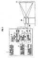
- Fig. 1 is a structural view showing an example of this multi-primary color (6-primary color) projection display device.
- the shown multi-primary color projection display device comprises a 6-primary color signal processing and converting block 1 and two DLP projectors 8A, 8B thereby to project an image on a screen 9.
- the 6-primary color signal processing and converting block 1 has two signal transmission routes for the DLP projectors 8A, 8B.
- dual-linked SDI signals from a decoder 2 are once stored in an output memory unit 3 and directly supplied to the DLP projectors 8A, 8B as they are in the form of TMDS (Transition Minimized Differential Signaling).
- the dual-linked SDI signals stored in the output memory unit 3 are once formatted by a format converter 4 and successively converted to 6-primary colors by a 3-6 color conversion unit 5. Then, the so-converted SDI signals are supplied to the DLP projectors 8A, 8B.
- the output memory unit 3 and the 3-6 color conversion unit 5 are together controlled in operation by a multi-primary color conversion workstation unit 6 and a 3-primary color conversion workstation unit 7, allowing the SDI signals to be converted to 3-primary colors up to 6-primary colors.
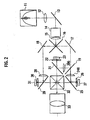
- the above-mentioned projection display may adopt another projector, for example, a LCOS projector shown in Fig. 2 .
- white light is emitted from a specified lamp (e.g. xenon lamp, ultra-high pressure mercury lamp, laser diode, light emission diode, etc.) in a lamp house 11.
- the white light is changed to a parallel light by a condenser lens 12 and successively reflected by a cold mirror 13 for eliminating UV light or IR light unnecessary for a display device or interposed optical components.
- the so-reflected light is transmitted through an integrator (rod integrator, flyeye integrator, etc.) 14 and a sequent field lens 15 thereby to enter a B/RG dichroic mirror 16.
- the B/RG dichroic minor 16 resolves incident illumination light to a light containing the wave bands of both red light and green light and a blue light, so that the forme light (red and green) enters a RG mirror 17, while the latter light (blue) enters a B mirror 18.
- the former light reflected by the RG mirror 17 its red light component is transmitted through a R/G dichroic mirror 19 thereby to enter an R field lens 24, while the green light component is reflected by the R/G dichroic minor 19 thereby to enter a G field lens 20.
- the blue light component reflected by the B mirror 18 it is transmitted through a B field lens 28 and the light's S-polarization component is reflected by a wire grid 29 thereby to enter a B device 31 through a B quarter-wave ( ⁇ /4) plate 30.
- the S-polarized light on light modulation is transmitted through the B quarter-wave ( ⁇ /4) plate 30 and the wire grid 29 thereby to enter the RGB composite dichroic prism 32.
- the RGB composite dichroic prism 32 recombines respective P-polarization components of incident green, red and blue lights on light modulation.
- the so-combined light is transmitted through a PJ lens 33 to form an image on a screen.
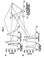
- the G device 23 and the B device 31 in the LCOS projector 8A have wavelength bands shown with R2, G2 and B2 in (A) of Fig. 3 , respectively.
- respective red, green and blue lights incident on the R device 27, the G device 23 and the B device 31 have wavelength bands shown with R1, G1 and B1 in (B) of Fig. 3 , respectively.
- the information about a color image formed on the screen 9 as a result of projecting lights through these projectors 8A and 8B is represented in a chromaticity diagram in (C) of Fig. 3 , by its 6-primary color reproduction range obtained by linking six wavelength bands with each other. Obviously, this 6-primary color reproduction range is wider than the above 4-primary color reproduction range. Thus, it becomes possible to reproduce even hematic color, purple and cobalt blue, all of which could not be reproduced by the conventional RGB color reproduction display system.
- the above-mentioned multi-primary color projection display device has begun to be used in an image evaluation where the quality of color reproduction plays a significant role, for instance, reproduction of art objects such as pictures and ceramic wares, reproduction of medical science images and so on.
- the conventional optical system and projection display device are apt to be increased in manufacturing cost and complicated in structure due to the presence of two projectors 8A, 8B.
- the conventional optical system and projection display device is not actualized or embodied without grants-in-aid of any public institution, for instance, government.
- the conventional optical system and projection display device have additional disadvantages. That is, as the projected images from two projectors 8A, 8B have to be superimposed on each other on the screen, the black level of the projected image is doubled due to the projectors 8A, 8B thereby to reduce contrast of the image to half. Consequently, the primary colors' reproduction is subjected to overlapping black (actually, dark gray), causing a cloudy image (in white-tinged primary colors) on the screen with a harrowed color reproduction range.
- an object of the present invention is to provide an optical system which can provide high-contrast images, multi-primary color images and 3-dimensional images by a structure for first dividing a light, which has been combined after modulating (1 st . modulation) lights by the conventional 3-primary color devices, into halves and secondly modulating the so-divided lights by their exclusive signals (2 nd . modulation).
- Another object of the present invention is provide an optical system and a projection display device both of which are low in manufacturing cost, needless of the adjustment in superimposing images and which can display even 3-dimensional images on a screen.
- an optical system comprising: a modulation optical system for combining respective modulated primary color lights with each other in wavelength thereby to produce and output a first composite light, the respective modulated primary color lights being provided by modulating 3-primary color lights by 3-primary color signals produced from an image signal individually, a color spectroscope for transmitting and reflecting the first composite light thereby to divide it into a second composite light composed of a plurality of first primary color components each having a wavelength bandwidth narrower than that of the respective primary colors' lights, and a third composite light composed of a plurality of second primary color components each having a wavelength bandwidth narrower than that of the respective primary colors' lights and different from, each of the wavelength bandwidths of the first primary color components; a modulator for modulating the second composite light by one of two kinds of luminance signals produced from the image signal thereby to produce a first modulation light and modulating the third composite light by the other of the luminance signals thereby to produce a second modulation light; a photosynthes
- a projection display device comprising, using a plurality of first primary color signals corresponding to a plurality of first primary color components produced by an input image signal of an image to be displayed and a plurality of second primary color signals corresponding to a plurality of second primary color components whose light wavelength bands are different from those of the first primary color components, the device comprising: a first signal generator for generating a first band-unlimited luminance signal based on the first primary color signals and a second band-unlimited luminance signal based on the second primary color signals; a second signal generator for band-limiting the first and second primary color signals thereby to calculate a maximum of each of the first and second band-limited primary color signals with respect to each pixel and generating third and fourth band-limited luminance signals based on each of the first and second band-limited primary color signals; a third signal generator for generating: first and second color-signal correction coefficients based on the maximum of the each of the first and second band-limited primary color signals with respect to each
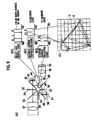
- Fig. 4 shows a constitution of an optical system in accordance with an embodiment of the present invention.
- the optical system of this embodiment comprises a first modulation optical system (RGB split-combine projection system) 101, a second modulation optical system (Y1Y2 image-combining part) 102, a quarter-wave plate 35 between the system 101 and the system 102 and a one-to-one (1:1) relay lens 36.
- the first modulation optical system 101 is adapted so as to modulate light by 3-primary color devices and is similar to the optical system of Fig. 1 without the PJ lens 33.
- the quarter-wave plate 35 rotates an S-polarized light as being a composite light of 3-primary color lights from the RGB composite dichroic prism 32 of the first modulation light system 101 by an angle of ⁇ /4.
- the so-rotated light is subsequently divided into two routes by a PS separation WG (wire grid) 37 in the second modulation optical system 102.
- PS separation WG wire grid
- the 1:1 relay lens 36 is provided to project images on display devices in the second modulation optical system 102, that is, a Y1 device 44 and a Y2 device 51. In this way, the second modulation optical system 102 forms a remarkable feature of this embodiment.
- the composite light consisting of RGB primary color lights modulated by the system 101 is transmitted through the 1:1 relay lens 36 and further divided into a P-polarized light and an S-polarized light by the PS separation WG 37 (e.g. product named "Moxtek") as being a WG type polarization split element.
- the S-polarized light is transmitted through a Y1 field lens 38 for fine adjustment of an image to be formed on the Y1 device 44 in terms of size and position and enters a left-sided (L-side) wavelength spectral filter 39 to select left-sided primary color components from 3-primary color lights shown in Fig. 5 . That is, there are selected a red light component R1 of 615 nm in wavelength, a green light component Gl of 515 nm in wavelength and a blue light component B 1 of 450 nm in wavelength, in the illustrated example.
- the S-polarized light of 3-primary color light components R1, G1 and B1 is shifted in wavelength of half-wave by a half-wave plate 40 to become a P-polrized light once. Thereafter, in order to enhance its optical quenching ratio, unnecessary S-polarized light component is eliminated from the P-polarized light by an analyzer 41. Then, through a Y1 WG (wire grid) 42 and a Y1 wavelength plate (retarder) 43 for regulating a phase of the light, it enters the Y1 device 44, attaining an image formation on modulation.
- a Y1 WG wire grid
- a Y1 wavelength plate (retarder) 43 for regulating a phase of the light
- the P-polarized light from the PS separation WG 37 is transmitted hough a Y2 field lens 45 for fine adjustment of an image to be formed on the Y2 device 51 in terms of size and position and enters a right-sided (R-side) wavelength spectral filter 46 to select right-sided primary colors components from 3-primary color lights shown in Fig. 5 . That is, there are selected a red light component R2 of 650 nm in wavelength, a green light component G2 of 550 nm in wavelength and a blue light component B2 of 475 nm in wavelength, in the illustrated example.
- the P-polarized light of 3-primary color light components R2, G2 and B2 enters a Y2 aberration correcting lens 47 to correct an aberration produced since the light emitted from the 1:1 relay lens 36 is transmitted through the PS separation WG 37 and a later-mentioned Y2 WG 49.
- the Y2 aberration correcting lens 47 is formed by either a cylindrical lens or a wedge glass, for example.
- LCOS Liquid Crystal on Silicon
- G device 23 the G device 23, the R device 27 and the B device 31.
- the S-polarized light modulated by the Y1 device 44 is transmitted through the Y1 wavelength plate 43 and further reflected by the Y1 WG 42 and enters a Y1 aberration correcting lens 52 to correct an astigmatism in passing through a PS composite WG 55 to which an optical axis is slanted by 45 degrees.
- the Y1 aberration correcting lens 52 is formed by either a cylindrical lens or a wedge glass, for example.
- the S-polarized light transmitted through the Y1 aberration correcting lens 52 is returned to a P-polarized light by a half-wave plate 53.
- P-polarized light component in actual, unnecessary S-polarized light component as the light passes through the plate 53
- P-polarized light permeable; S-polarized light: impermeable
- the so-filtered light enters the PS composite WG 55.
- the Y1 analyzer 54 is inclined to a lens optical axis by approx. 10 degrees so that a reflection light from the analyzer 54 does not return to the Y1 device 44.
- the S-polarized light modulated by the Y2 device 51 is transmitted through the Y2 wavelength plate 50 and further reflected by the Y2 WG 49 and enters a Y2 analyzer 56 to eliminate P-polarized light component from the S-polarized light Then, the so-filtered light enters the PS composite WG 55.
- the Y2 analyzer 56 is also inclined to a lens optical axis by approx. 10 degrees so that a reflection light from the analyzer 54 does not return to the Y2 device 51.
- the PS composite WG 55 combines the P-polazized light modulated by the Y1 device 44 and successively transmitted through the Y1 analyzer 54 with the S-polarized light modulated by the Y2 device 51 and successively transmitted through the Y2 analyzer 56.
- the resulting composite light is projected on a screen (not shown) through a Y1Y2 projector lens 57.
- the Y1 device 44 and the Y2 device 51 are adapted so as to be displaced by micro-motors, allowing their characteristics to be identical to each other in terms of the number of pixels.
- the composite light (RGB primary color lights) from the RGB composite dichroic prism 32 is once divided, through the L-side wavelength spectral filter 39 and the R-side wavelength spectral filter 46 in the second modulation optical system 102, into the first 3-primary color light (light components R1, G1, B1) and the second 3-primary color light (light components R2, G2, B2) and thereafter, images are formed on the Y1 device 44 and the Y2 device 51 for modulation.
- respective modulated lights from the devices 44, 52 are again combined with each other by the PS composite WG 55, a 6-primary color image is projected on the screen.
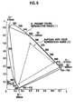
- Fig. 6 is a general X-Y chromaticity diagram defined by IEC390. This X-Y chromaticity diagram shows a color gamut that a human being is capable of detecting. Although the reproducible color gamut for a display device, a projector or the like is believed to be wide as possible, the actual reproducible color gamut for the display almost falls from 420 nm to 700 nm by reason that light having a wavelength less than 420 nm (near UV light) and light having a wavelength more than 700 nm (near infrared light) should be filtered in view of ensuring the safety against human bodies and the reliability of optical components.
- 420 nm near UV light
- 700 nm near infrared light
- the reproducible color gamut I of this embodiment is broader than (more than twice as broad) the reproducible color gamut II for HDTV defined by SMPTE240 (shown with a triangle of broken lines) and also extends up to more than 90% of the reproducible color gamut that a human being is capable of detecting, accomplishing remarkably-broad color reproduction in comparison with the conventional system.
- the L-side wavelength spectral filter 39 may be arranged in front of the analyzer 41 on the incident side of the Y1 device 44 or in front of the Y1 analyzer 54 on the emission side of the Y1 device 44.
- the R-side wavelength spectral filter 46 may be arranged in front of the analyzer 48 on the incident side of the Y2 device 51 or in front of the Y2 analyzer 56 on the emission side of the Y2 device 51.
- LCOS having 4,096 pixels in the horizontal direction and 2,160 pixels in the vertical direction whose resolving power is equal to that of the Y1 device 44 and the Y2 device 51, is adopted for the G device 23, the R device 27 and the B device 31.
- each of these devices 23, 27, 31 in the first modulation optical system 101 may be provided with lower resolving power (e.g. elements corresponding to HDTV having 2,048 pixels in the horizontal direction and 1,080 pixels in the vertical direction) since the devices are adapted so as to operate in chrominance.
- the resolving power of an image modulated by the Y1 devices 44 and the Y2 device 51 depends on respective resolving powers of the Y1 devices 44 and the Y2 device 51 finally
- Fig. 7 is a combination diagram of the second embodiment shown with a part (A) and the third embodiment shown with a part (B).
- the part (A) shows a constitution of a substantial part of the optical system in accordance with the second embodiment
- the part (B) shows a constitution of a substantial part of the optical system in accordance with the third embodiment.
- a dichroic mirror (DM) is adopted as a color separator.
- the optical system does not employ the wavelength spectral filters 39, 46 in the second modulation optical system 102 of Fig. 4 .
- a dichroic mirror 60 and a dichroic mirror 61 in place of the PS separation WG 37 and the PS composite WG 55 of the first embodiment in order to realize 6-primary colors.
- the composite light as a result of combining 3-primary colors RGB all modulated in the first modulation optical system 101 has a spectrum shown in (C1) of Fig. 7 .
- This composite light is transmitted through the 1:1 relay lens 36 thereby to enter the first dichroic mirror (DM1) 60.
- the red light component R1 having a wavelength of 615 nm, the green light component G2 having a wavelength of 550 nm and the blue light component B1 having a wavelength of 450 nm, all of which are shown in (C2) of Fig. 7 are transmitted through the first dichroic mirror (DM1) 60.
- the red light component R2 having a wavelength of 650 nm, the green light component G1 having a wavelength of 515 nm and the blue light component B2 having a wavelength of 450 nm, all of which are shown in (C3) of Fig. 7 are reflected by the first dichroic mirror (DM1) 60.
- the reflected composite light of the components R2, G1, B2 enters the Y1 device 44 to form an image on modulation.
- the composite light of the components R1, G2, B1 transmitted through the first dichroic mirror (DM1) 60 enters the Y2 device 51 to form an image on modulation through the Y2 field lens 45, the aberration correcting lens 47, the analyzer 48, the Y2 WG 49 and the Y2 wavelength plate 50 in this order.
- the S-polarized light emitted from the Y1 device 44 for modulation is transmitted through the Y1 wavelength plate 43 and further reflected by the Y1 WG 42. Then, the S-polarized light is changed to a P-polarized light through the Y1 aberration correcting lens 52, the half-wave plate 53 and the Y1 analyzer 54 thereby to enter the second dichroic mirror (DM2) 61.
- the S-polarized light emitted from the Y2 device 51 for modulation is transmitted through the Y1 wavelength plate 50 and further reflected by the Y2 WG 49. Then, the so-reflected S-polanzed light enters the second dichroic mirror (DM2) 61 through the Y2 analyzer 56.
- the second dichroic mirror (DM2) 61 is established so as to be opposite to the first dichroic mirror (DM1) 60 in terms of transmittance-reflectance characteristics. Therefore, one light, which is composed of wavelength light components reflected by the dichroic mirror (DM1) 60 and further modulated by the Y1 device 44 after being changed to a P-polarized light by the half-wave plate 53, is transmitted through the dichroic mirror (DM2) 61. While, the S-polarized light, which is composed of wavelength light components transmitted through the dichroic mirror (DM1) 60 and modulated by the Y2 device 51, is reflected by the dichroic mirror (DM2) 61. Consequently, at the dichroic mirror (DM2) 61, the former light and the latter S-polarized light are combined with each other and subsequently projected on a not-shown screen by the Y1Y2 projector lens 57.
- the X-Y chromaticity diagram of light of the second embodiment is illustrated by a reproducible color gamut III shown with solid lines in (D) of Fig. 7 .
- the color gamut III is provided with a periphery extending from violet (wavelength: 400 nm) up to crimson (wavelength: 700 nm), representing a remarkably broad reproducible color gamut in comparison with the reproducible color gamut II under HDTV (SMPTE240) standard on general use.
- the system of the second embodiment does not adopt the wavelength spectral filters 39, 46, the PS separation WG 37 and the PS composite WG 55 of the first embodiment, the transmission efficiency gets better thereby to improve the light utilization efficiency.
- the dichroic mirrors 60, 62 may be replaced by wavelength selection filters or the like (e.g. "Color-Select" -registered trademark).
- the third embodiment of the invention will be described with reference to (B) of Fig. 7 .
- the third embodiment differs from the first embodiment in the arrangement of the Y1 device 44 and the Y2 device 51.
- the lights emitted from the Y1 device 44 and the Y2 device 51 are transmitted through the Y1 WG 42 and the Y2 WG 49, respectively
- the dichroic mirror 61 of the second embodiment is replaced by the PS composite WG 55.
- the transmitted composite light of the components R1, G2, B1 through the dichroic minor (DM1) 60 is transmitted through the Y2 field lens 45 and the analyzer 48 thereby to become an S-polarizad light
- This light is subsequently reflected by the Y2 WG 49 and further transmitted through the Y2 wavelength plate 50 thereby to enter the Y2 device 51 to form an image on modulation.
- the Y1 device 44 emits a modulated P-polarized light.
- the P-polarized light is transmitted through the Y1 wavelength plate 43, the Y1 WG 42, the Y1 aberration correcting lens 52 and the Y1 analyzer 54 thereby to enter the PS composite WG 55.
- the Y2 device 51 emits a modulated P-polarized light
- the P-polarized light enters the half-wave plate 63 through the Y2 aberration correcting lens 62 thereby to become an S-polarized light.
- the S-polarized light its unnecessary components are eliminated by the Y2 analyzer 56 and thereafter, the so-filtered light enters the PS composite WG 55.
- the PS composite WG 55 combines the P-polarized light from the Y1 analyzer 54 with the S-polarized light from the Y2 analyzer 56 and further projects a resulting composite light onto a not shown screen through the Y1Y2 projector lens 57.
- the X-Y chromaticity diagram of light of the third embodiment is illustrated by a reproducible color gamut III shown with solid lines in (D) of Fig. 7 as well as the second embodiment of (A).
- the color gamut III is provided with a periphery extending from violet (wavelength: 400 mm) up to crimson (wavelength: 700 nm), representing a remarkably broad reproducible color gamut in comparison with the reproducible color gamut II under HDTV (SMPTE240) standard on general use.
- the third embodiment is advantageous in constitution due to the adoption of the PS composite WG 55. Nevertheless, it should be noted that the half-wave plate 63 and the Y2 aberration correcting lens 62 have to be arranged on the side of the Y2 device 51 due to the adoption ofPS composite system.
- a part (A) shows a constitution of the substantial part of the optical system in accordance with the fourth embodiment of the present invention.
- elements identical to those of the third embodiment in (B) of Fig. 7 are indicated with the same reference numerals and their overlapping descriptions are eliminated.
- the feature of the fourth embodiment resides in the provision of a dichroic mirror 65 having the band-separation characteristic in (B2), (B3) of Fig. 8 or (C2), (C3) of Fig. 8 in place of the dichroic mirror 60 of the third embodiment.
- the composite light from the first modulation optical system 101 has a spectrum shown in (B1) of Fig. 8 .
- This composite light is transmitted through the 1:1 relay lens 36 thereby to enter the dichroic mirror 65 through which the red light component R2, the green light component G and the blue light component B1 are transmitted as shown in (B2) of Fig. 8 and on which the red light component R1 and the blue light component B2 are reflected as shown in (B3) of Fig. 8 .
- the reflected composite light of the components R1 and B2 from the dichroic mirror 65 is transmitted through the Y1 field lens 38 and the analyzer 41 thereby to become an S-polarized light.
- This light is subsequently reflected by the Y1 WG 42 and further transmitted through the Y1 wavelength plate 43 thereby to enter the Y1 device 44 to form an image on modulation.
- the transmitted composite light of the components R2, G, B 1 through the dichroic mirror 65 is transmitted through the Y2 field lens 45 and the analyzer 48 thereby to become an S-polarized light.
- This light is subsequently reflected by the Y2 WG 49 and further transmitted through the Y2 wavelength plate 50 thereby to enter the Y2 device 51 to form an image on modulation.
- the lights modulated by the Y1 device 44 and the Y2 device 51 are transmitted through the similar optical system to the third embodiment and subsequently subjected to PS composition. Thereafter, the resulting composite light is projected on a screen (not shown) through the Y1Y2 projector lens 57.
- the dichroic mirror 65 has a band-separation characteristic to divide the red light band and the blue light band into halves respectively. Consequently, the X-Y chromaticity diagram of light of the fourth embodiment represents a reproducible color gamut of five primary colors shown with solid line IV in (D) of Fig. 8 . Obviously, this reproducible color gamut of five primary colors is broader than the reproducible color gamut II under HDTV (SMPTE240) standard on general use, accomplishing an accurate color reproduction in comparison with HDTV (SMPTE240) standard.
- the dichroic mirror 65 may be provided with a band-separation characterise shown in (C2), (C3) of Fig. 8 .
- This modification is directed to a situation where the incident light from the first modulation optical system has the green light band (G) and the red light band (R) each established broader than the blue light band (B), as shown with the spectrum of (C1) of Fig. 8 .
- the dichroic mirror 65 has a band-separation characteristic to divide the green light band and the red light band into halves respectively. That is, the green light component G1 and the red light component R2 are transmitted through the dichroic mirror 65, as shown in (C2) of Fig. 8 . On the contrary, the blue light component B, the green light component G2 and the red light component R1 are reflected by the dichroic mirror 65, as shown in (C3) of Fig. 8 .
- the X-Y chromaticity diagram of light of this modification represents a reproducible color gamut of five primary colors shown with a solid line V in (E) of Fig. 8 .
- this reproducible color gamut of five primary colors is broader than the reproducible color gamut II under HDTV (SMPTE240) standard on general use, accomplishing an accurate color reproduction in comparison with HDTV (SMPTE240) standard.
- a part (B) shows a constitution of the substantial part of the optical system in accordance with the fifth embodiment of the present invention.
- elements identical to those of the fourth embodiment in (B) of Fig. 8 are indicated with the same reference numerals and their overlapping descriptions are eliminated.
- the feature of the fifth embodiment resides in the provision of a dichroic mirror 66 having the band-separation characteristic in (B2), (B3) of Fig. 9 in place of the dichroic mirror 60 of the third embodiment
- the composite light from the first modulation optical system 101 has a spectrum shown in (B1) of Fig. 9 .
- This composite light is transmitted through the 1:1 relay lens 36 thereby to enter the dichroic mirror 66 through which the green light component G1 and the red light component R are transmitted as shown in (B2) of Fig. 9 and on which the blue light component B and the green light component G2 are reflected as shown in (B3) of Fig. 9 .
- the reflected composite light of the components R and G1 from the dichroic mirror 66 is transmitted through the Y1 field lens 38 and the analyzer 41 thereby to become an S-polarized light.
- This light is subsequently reflected by the Y1 WG 42 and further transmitted through the Y1 wavelength plate 43 thereby to enter the Y1 device 44 to form an image on modulation.
- the transmitted composite light of the components B, G2 through the dichroic mirror 66 is transmitted through the Y2 field lens 45 and the analyzer 48 thereby to become an S-polarized light.
- This light is subsequently reflected by the Y2 WG 49 and further transmitted through the Y2 wavelength plate 50 thereby to enter the Y2 device 51 to form an image on modulation.
- the lights modulated by the Y1 device 44 and the Y2 device 51 are transmitted through the similar optical system to the third and fourth embodiments and subsequently subjected to PS composition. Thereafter, the resulting composite light is projected on a screen (not shown) through the Y1 Y2 projector lens 57.
- the fifth embodiment in (A) of Fig. 9 is directed to a situation where the incident light from the first modulation optical system has the green light band (G) established broader than the blue light band (B) and the red light band (R), as shown with the spectrum in (B1) of Fig. 9 .
- the dichroic mirror 66 has a band-separation characteristic to divide the green light band into halves, as shown in (B2), (B3) of Fig. 9 .
- the X-Y chromaticity diagram of light of the fifth embodiment represents a reproducible color gamut of 4-primary colors shown with a solid line VI in (C) of Fig. 9 .
- this reproducible color gamut of 4-primary colors is broader than the reproducible color gamut II under HDTV (SMPTE240) standard on general use, accomplishing an accurate color reproduction in comparison with HDTV standard.
- the reproducible color gamut of 4-primary colors could be attained by the dichroic mirror's dividing of either the blue light band or the red light band into halves.
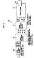
- the projection display device 70 comprises a Super Hi-Vision camera 71 for taking a picture of a desired object, a Super Hi-Vision recorder 72 for recording and reproducing imaging signals of the Super Hi-Vision camera 71, a matrix conversion decoder 73 that inputs green signals G1 and G2, a red signal R and a blue signal B from the recorder 72 and outputs two kinds of luminance signals Y1, Y2 and color signals 'r', "g" and "b” as a result of matrix conversion of the above input signals and an optical system 74 for projecting an optical image on a not-shown screen.
- a Super Hi-Vision camera 71 for taking a picture of a desired object
- a Super Hi-Vision recorder 72 for recording and reproducing imaging signals of the Super Hi-Vision camera 71
- a matrix conversion decoder 73 that inputs green signals G1 and G2, a red signal R and a blue signal B from the recorder 72 and outputs two kinds of luminance signals Y1, Y2 and color signals
- the Super Hi-Vision is one of a LSDI (Large Screen Digital Imagery) system with 7680 ⁇ 4320 pixels specified in Recommendation ITU-R BT.1769 "parameter values for an expanded hierarchy of LSDI image formats for production and international program exchange".
- LSDI Large Screen Digital Imagery
- the Super Hi-Vision camera 71 is adapted so that each solid-state image sensing device outputs primary color signals of 10 bits.
- the optical system 74 corresponds to one system to be selected from the embodiments described with reference to Figs. 4 to 9 optionally.
- the matrix conversion decoder 73 is adapted so as to provide five kinds of signals, that is, the above luminance signals Y1, Y2 and the color signals "r", "g" and "b".
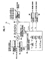
- Fig. 11 is a block diagram of the matrix conversion decoder 73 used in the above embodiment providing the reproducible color gamut of 6-primary colors.
- the matrix conversion decoder 73 inputs image signals of 6-primary colors comprising e.g. respective signals of R1 (wavelength: 615 nm), G1 (515 nm), B1 (450 nm), R2 (650 mn), G2 (550 nm) and B2 (475 nm) of Fig. 5 .
- an inverse gamma ( ⁇ ) correcting section 81 once applies an inverse gamma ( ⁇ ) correction to these image signals thereby to bring them back to ⁇ 1-linear signals for facilitating an internal calculation.
- a Y1Y2 generating section 82 drafts a luminance signal Y 1FULL in a frequency band (band-unlimited) by the first 3-primary color signals R1, G1 and B1 and a luminance signal Y 2FULL in a frequency band (band-unlimited) by the second 3-primary color signals R2, G2 and B2.
- a lowpass filter (PLF) 83 attenuates respective high-frequency components of the 6-primary color signals from the inverse gamma ( ⁇ ) correcting section 81 thereby to pick up 6-primary color signals R 1-LPF , G 1-LPF , B 1-LPF , R 2-LPF , G 2-LPF and B 2-LPP of low frequency components and successively send these pickup signals to both a maximum/Y1Y2 calculating section 84 and a multiplier 86.
- the maximum/Y1Y2 calculating section 84 calculates a maximum MAX1 of the "band-limited" fust 3-primary color signals R 1-LPF , G 1-LPF and B 1-LPF and a maximum MAX2 of the "band-limited" second 3-primary color signals R 2-LPF , G 2-LPF and B 2-LPF with respect to each pixel.
- the maximuna/Y1Y2 calculating section 84 calculates a low-frequency component Y 1-LPF of the first luminance signal by the "band-limited" first 3-primary color signals R 1-LPF , G 1-LPF and B 1-LPF and a low-frequency component Y 2-LPF of the second luminance signal by the "band-limited" second 3-primary color signals R 2-LPF , G 2-LPF and B 2-LPF .
- a coefficient/luminance signal generating section 85 inputs the luminance signals Y 1FULL and Y 2FULL from the Y1Y2 generating section 82, the maximums MAX1 and MAX2 from the maximum/Y1Y2 calculating section 84 and the low-frequency components Y 1-LPF and Y 2-LPF of the luminance signals from the same section 84.
- the coefficient/luminance signal generating section 85 calculates coefficients C 1 , C 2 and luminance signals Y 1 , Y 2 by the following computing equations (wherein A1, A2 are constants for gains):
- C 1 A ⁇ 1 ⁇ MAX ⁇ 1 - 1 / 2
- C 2 A ⁇ 2 ⁇ MAX ⁇ 2 - 1 / 2
- Y 1 A ⁇ 1 ⁇ Y IFULL ⁇ MAX ⁇ 1 1 / 2 / Y 1 - LPF
- Y 2 A ⁇ 2 ⁇ Y 2 ⁇ FULL ⁇ MAX ⁇ 2 1 / 2 / Y 2 - LPF
- C 1 , C 2 are coefficients for minimizing flare components of light projected on a screen.
- the multiplier 86 uses the 6-primary color signals R 1-LPF , G 1-LPF , B 1-LPF , R 2-LPF , G 2-LPF and B 2-LPF of low-frequency components from the LPF 83 and the coefficients C 1 , C 2 from the coefficient/luminance signal generating section 85, the multiplier 86 generate the red signal "r", the green signal "g" and the blue signal "b" each more than 8 bits by the following computing equations.
- a Y1 gamma, ( ⁇ ) correcting section 88 applies a gamma ( ⁇ ) correction to the luminance signal Y 1 from the coefficient/lumninance signal generating section 85 and further supplies, for example, the Y1 device 44 of Fig. 4 with the so-corrected signal as a Y1 picture signal more than 8 bits.
- a Y2 gamma ( ⁇ ) correcting section 89 applies a gamma ( ⁇ ) correction to the luminance signal Y 2 from the coefficient/luminance signal generating section 85 and further supplies the Y2 device 51 of Fig. 4 with the so-corrected signal as a Y2 picture signal more than 8 bits.
- the matrix conversion decoder 73 supplies the luminance signals Y1, Y2 and the color signals "r", "g” and "b” to the optical system 74. Then, through the optical system 74, a multicolor image with more than 4 primary colors is projected on the screen (not shown).
- the optical system 74 corresponds to one system to be selected from the embodiments described with reference to Figs. 4 to 9 optionally
- the composite light which is composed of 3-primary color (RGB) lights modulated by the first modulation optical system 101, is divided into the first light composed of three or two primary color light and the second light composed of three or two primary color lights, the second light having a different wavelength band from the first light, in the second modulation optical system 102.
- the first light is modulated by the Y1 device 44, while the second light is modulated by the Y2 device 51 and successively, these modulated lights are combined to each other. Accordingly, with the above-mentioned constitution, it becomes possible to display a picture colored in multicolor more than 4 primary colors, allowing a single projector to accomplish an accurate color reproduction in comparison with HDTV (SMPTE 20) standard.
- HDTV HDTV
- the optical system of the invention Comparing with a normal projector having a contrast of the ratio of few thousands: 1, the optical system of the invention is capable of realizing an image at higher contrast exceeding the ratio of million: 1 since such double-modulation by the first and second modulation optical systems allows a multiplication of their first and second contrasts (e.g. 1000 X 1000 in case of 1000: 1 each). Furthermore owing to the displaying in multi-primary colors, the optical system of the invention can display an image in a reproducible color gamut substantially covering the color gamut that a human being is capable of detecting (e.g. CrE930 chromaticity diagram), allowing a reproduction of colors that could't been reproduced by conventional TVs or cinema films.
- a reproducible color gamut substantially covering the color gamut that a human being is capable of detecting (e.g. CrE930 chromaticity diagram), allowing a reproduction of colors that could't been reproduced by conventional TVs or cinema films.
- the projection display device of the invention can make a significant contribution to the iconic reproduction of pictures, craft objects, designs, natures, etc. thereby to provide them with culturally-immeasurable values in spite of their aging, deterioration or disappearance in actuality.
- the optical system is equipped with a single projector (projection display device) and also adapted so as to project a composite light composed of two lights modulated by the Y1 device 44 and the Y2 device 51
- the projector lens 57 has only to be provided with distortion at the conventional design level. Furthermore, there is no need of converting input signals through CGP etc. in order to align images with each other. For these reasons, it is possible to improve installation easiness of the optical system and its production cost remarkably.
- Fig. 12 is a structural view of a substantial part of the optical system in the application of the present invention.
- elements identical to those of the optical system of Fig. 4 are indicated with the same reference numerals and their overlapping descriptions are eliminated.
- the feature of the application in Fig. 12 resides in the replacement of the wavelength spectral filters 39, 46 of Fig. 4 by wavelength spectral filter 91, 92.
- the previous wavelength spectral filter 39 of Fig. 4 is adapted so as to select the red light component R1, the green light component G1 and the blue light component B1 out of the 3-primary color lights of Fig. 5
- the wavelength spectral filter 46 is adapted so as to select the red light component R2, the green light component G2 and the blue light component B2.
- respective light components in the wavelength bands R1, G1 and B 1 selected by the wavelength spectral filter 91 are identical to 3 primary color light components modulated by an image signal for human's right eye
- respective light components in the wavelength bands R2, G2 and B2 selected by the wavelength spectral filter 92 are identical to 3 primary color light components modulated by an image signal for human's left eye.
- the same light components are further modulated by the Y1 device 44 with a luminance signal for the right-eye image signals.
- the same light components are further modulated by the Y2 device 51 with a luminance signal for the left-eye image signals.
- stereo-glasses 95 comprising a right eyeglass having the same wavelength selectivity as the wavelength spectral filter 91 and a left eyeglass having the same wavelength selectivity as the wavelength spectral filter 92, whereby the image projected on the screen 93 can be recognized as one stereoimage in the audience's head.
- the optical system of the present invention could make the object 3-dimensional with ultia-high contrast if only allowing the input signals to correspond to 3 dimensional signals.
- an art object of which color reproduction should be emphasized e.g. picture, photograph
- the screen 93 may comprise a white screen having a gain of 1.0 and therefore, any screen could reproduce a stereoimage.
- the optical system of the invention is constructed so as to project an image through a single lens (not stacked projectors), the image-projection could be attained without correcting imaging signals in even a modified screen (e.g. curved screen).
- the present invention it is possible to attain the 6-primary color reproduction by a single projector and also possible to display a image at high contrast. Therefore, the present invention is applicable to a variety of color reproduction fields, for example, evaluations of car design, art objects, craftworks, printings, medical images, etc. Further, owing to the provision of high-resolution picture of pixels more than 4k in the horizontal direction, mtional-treasure type art objects, movies, pictures, etc. can be preserved as they were discovered or manufactured, in the form of image data. Further, the present invention is also applicable to medical image displays, such as roentgen television and operating monitor.
- Fig. 12 requires the stereo-glasses 95
- the illustrated display device may be utilized as an optical system for 3-dimeosional images. Therefore, the present invention is applicable to a variety of fields, for example, industrial design, games, simulator, etc.
Landscapes
- Engineering & Computer Science (AREA)
- Multimedia (AREA)
- Signal Processing (AREA)
- Physics & Mathematics (AREA)
- Spectroscopy & Molecular Physics (AREA)
- General Physics & Mathematics (AREA)
- Projection Apparatus (AREA)
- Transforming Electric Information Into Light Information (AREA)
- Video Image Reproduction Devices For Color Tv Systems (AREA)
- Testing, Inspecting, Measuring Of Stereoscopic Televisions And Televisions (AREA)
- Stereoscopic And Panoramic Photography (AREA)
Abstract
Description
- The present invention relates to an optical system and a projection display device. Particularly, the present invention relates to an optical system and a projection display device both of which can provide high-contrast images and multi-primary color/3-dimensional images for a projection type projector.
- Conventionally, a 3-panel type projector using three pieces (red, green, blue) of modulation devices is general in the projection display device (projector). Depending on the kind of devices, the 3-panel type projectors comprise LCD (Liquid Crystal Display) projector, DLP (Digital Light Processing) projector, LCOS (Liquid Crystal on Silicon) projector and so on. However, there is a possibility that precise color reproduction couldn't be attained by only a single 3-panel type projector since its reproducible area is limited to an area represented as the sum of 3-dimensional color vectors in a 3-dimentional color space.
- Therefore, there are proposed multi-primary color projectors each using four or more colors in order to attain more accurate color reproduction (e.g. Japanese Patent Laid-Open Publication Nos.
2000-253263 2000-338950 - Meanwhile, there is also known a multi-primary color (6-primary color) projection display device having a boarder color reproduction range than that of the above projector adopting 4-primary colors (e.g. Masahiro Yamaguchi et al., "High-fidelity video and still-image communication based on spectral information: Natural Vision System and its applications", http://www.is1.titech.ac.jp/ guchi/NV/EI106-6062-16c.pdf, Searching Date: October 5, 2007).
Fig. 1 is a structural view showing an example of this multi-primary color (6-primary color) projection display device. The shown multi-primary color projection display device comprises a 6-primary color signal processing and converting block 1 and twoDLP projectors screen 9. - The 6-primary color signal processing and converting block 1 has two signal transmission routes for the
DLP projectors output memory unit 3 and directly supplied to theDLP projectors output memory unit 3 are once formatted by aformat converter 4 and successively converted to 6-primary colors by a 3-6 color conversion unit 5. Then, the so-converted SDI signals are supplied to theDLP projectors output memory unit 3 and the 3-6 color conversion unit 5 are together controlled in operation by a multi-primary colorconversion workstation unit 6 and a 3-primary colorconversion workstation unit 7, allowing the SDI signals to be converted to 3-primary colors up to 6-primary colors. - Besides the
DLP projectors Fig. 2 . InFig. 2 , white light is emitted from a specified lamp (e.g. xenon lamp, ultra-high pressure mercury lamp, laser diode, light emission diode, etc.) in alamp house 11. Then, the white light is changed to a parallel light by acondenser lens 12 and successively reflected by acold mirror 13 for eliminating UV light or IR light unnecessary for a display device or interposed optical components. Then, the so-reflected light is transmitted through an integrator (rod integrator, flyeye integrator, etc.) 14 and asequent field lens 15 thereby to enter a B/RGdichroic mirror 16. - The B/RG dichroic minor 16 resolves incident illumination light to a light containing the wave bands of both red light and green light and a blue light, so that the forme light (red and green) enters a
RG mirror 17, while the latter light (blue) enters aB mirror 18. In the former light reflected by theRG mirror 17, its red light component is transmitted through a R/Gdichroic mirror 19 thereby to enter anR field lens 24, while the green light component is reflected by the R/G dichroic minor 19 thereby to enter aG field lens 20. - Regarding the green light component transmitted through the
G field lens 20 and the red light component transmitted throughR field lens 24, their S-polarization components are reflected bywire grids G device 23 and anR device 27 through a G quarter-wave (λ/4)plate 22 and an R quarter-wave (λ/4)plate 26, respectively. After light modulation at theG device 23 and theR device 27 with green signal and red signal of an image to be displayed from the 6-primary color signal processing and converting block 1, their P-polarized lights on light modulation are transmitted through the G, R quarter-wave (λ/4)plates wire grids composite dichroic prism 32. - On the other hand, regarding the blue light component reflected by the
B mirror 18, it is transmitted through aB field lens 28 and the light's S-polarization component is reflected by awire grid 29 thereby to enter aB device 31 through a B quarter-wave (λ/4)plate 30. After light modulation at theB device 31 with blue signal of the image to be displayed from the 6-primary color signal processing and converting block 1, the S-polarized light on light modulation is transmitted through the B quarter-wave (λ/4)plate 30 and thewire grid 29 thereby to enter the RGBcomposite dichroic prism 32. - The RGB
composite dichroic prism 32 recombines respective P-polarization components of incident green, red and blue lights on light modulation. The so-combined light is transmitted through aPJ lens 33 to form an image on a screen. - Depending on the characteristics of the
RG mirror 17, theB mirror 18 and the R/Gdichroic mirror 19, respective red, green and blue lights incident on theR device 27, theG device 23 and theB device 31 in theLCOS projector 8A have wavelength bands shown with R2, G2 and B2 in (A) ofFig. 3 , respectively. On the other hand, in the LCOSprojector 8B, respective red, green and blue lights incident on theR device 27, theG device 23 and theB device 31 have wavelength bands shown with R1, G1 and B1 in (B) ofFig. 3 , respectively. Therefore, the information about a color image formed on thescreen 9 as a result of projecting lights through theseprojectors Fig. 3 , by its 6-primary color reproduction range obtained by linking six wavelength bands with each other. Obviously, this 6-primary color reproduction range is wider than the above 4-primary color reproduction range. Thus, it becomes possible to reproduce even hematic color, purple and cobalt blue, all of which could not be reproduced by the conventional RGB color reproduction display system. For this reason, the above-mentioned multi-primary color projection display device has begun to be used in an image evaluation where the quality of color reproduction plays a significant role, for instance, reproduction of art objects such as pictures and ceramic wares, reproduction of medical science images and so on. - In another prior art, there is also known a multi-color or three-dimensional display device which utilizes a RGB color band separation filter in addition to two projectors in piles (e.g. combination of one projector for audience's left eye and another projector for right eye) (see http://www2.aimetne.jp/nakahara/3dart/3generi9.html, Search Date: October 9, 2007).
- In common with the conventional optical system and projection display device of
Figs. 1 and2 , however, it is required to prepare twoprojectors Fig. 3 and also supply theprojectors projectors screen 9 with respect to each pixel, thePJ lens 33 has to be designed with a projection distortion less than 0.05% (corresponding to a ratio of 1 pixel to 2000 pixels). Depending on a type ofscreen 9 to be installed, nevertheless, there is a possibility that a signal processing using CGP (Computer Graphic Processor) is required to correct a distortion in aligning respective images from theprojectors - In this way, the conventional optical system and projection display device are apt to be increased in manufacturing cost and complicated in structure due to the presence of two
projectors - The conventional optical system and projection display device have additional disadvantages. That is, as the projected images from two
projectors projectors - Under the above-mentioned problems, an object of the present invention is to provide an optical system which can provide high-contrast images, multi-primary color images and 3-dimensional images by a structure for first dividing a light, which has been combined after modulating (1st. modulation) lights by the conventional 3-primary color devices, into halves and secondly modulating the so-divided lights by their exclusive signals (2nd. modulation). Another object of the present invention is provide an optical system and a projection display device both of which are low in manufacturing cost, needless of the adjustment in superimposing images and which can display even 3-dimensional images on a screen.
- In order to achieve the above objects, there is provided an optical system comprising: a modulation optical system for combining respective modulated primary color lights with each other in wavelength thereby to produce and output a first composite light, the respective modulated primary color lights being provided by modulating 3-primary color lights by 3-primary color signals produced from an image signal individually, a color spectroscope for transmitting and reflecting the first composite light thereby to divide it into a second composite light composed of a plurality of first primary color components each having a wavelength bandwidth narrower than that of the respective primary colors' lights, and a third composite light composed of a plurality of second primary color components each having a wavelength bandwidth narrower than that of the respective primary colors' lights and different from, each of the wavelength bandwidths of the first primary color components; a modulator for modulating the second composite light by one of two kinds of luminance signals produced from the image signal thereby to produce a first modulation light and modulating the third composite light by the other of the luminance signals thereby to produce a second modulation light; a photosynthesizer for combining the first modulation light with the second modulation light thereby to produce a fourth composite light; and a projector for projecting the fourth composite light.
- In order to achieve the above objects, there is also provided a projection display device comprising, using a plurality of first primary color signals corresponding to a plurality of first primary color components produced by an input image signal of an image to be displayed and a plurality of second primary color signals corresponding to a plurality of second primary color components whose light wavelength bands are different from those of the first primary color components, the device comprising: a first signal generator for generating a first band-unlimited luminance signal based on the first primary color signals and a second band-unlimited luminance signal based on the second primary color signals; a second signal generator for band-limiting the first and second primary color signals thereby to calculate a maximum of each of the first and second band-limited primary color signals with respect to each pixel and generating third and fourth band-limited luminance signals based on each of the first and second band-limited primary color signals; a third signal generator for generating: first and second color-signal correction coefficients based on the maximum of the each of the first and second band-limited primary color signals with respect to each pixel, the maximum obtained by the second signal generator, a first display luminance signal based on the maximum of the each of the first and second band-limited primary color signals with respect to each pixel and the first and third luminance signals, and a second display luminance signal based on the maximum of the each of the first and second band-limited primary color signals with respect to each pixel and the second and fourth luminance signals; a fourth signal generator for generating 3-primary color display signals, based on the first and second color-signal correction coefficients and the first and second band-limited primary color signals; a modulation optical system that wavelength-combines respective modulation primary color signals obtained by modulating the 3-primary color display signals with respect to each primary color thereby to produce and output a first composite light; a color spectroscope for dividing the first composite light into a second composite light composed of the first primary color components and a third composite light composed of the second primary color components thereby to emit the second and third composite lights; a modulator for modulating the second composite light by the first display luminance signal thereby to produce a first modulation light and modulating the third composite light by the second display luminance signal to produce a second modulation light; a photosynthesizer for combining the first modulation light with the second modulation light thereby to produce a fourth composite light; and projector means for projecting the fourth composite light
-
-
Fig. 1 is a structural view of a prior art projection display device; -
Fig. 2 is a structural view of a projector ofFig. 1 ; -
Fig. 3 is a diagram explaining a color reproduction range of the device ofFig. 1 ; -
Fig. 4 is a structural view of an optical system in accordance with a first embodiment of the present invention; -
Fig. 5 is a diagram explaining the spectral sensitivity characteristic of a wavelength spectral filter ofFig. 4 ; -
Fig. 6 is a general X-Y chromaticity diagram defined by IEC390 and a color reproduction range etc. of the first embodiment of the present invention; -
Fig. 7 is a view having structural views of substantial parts of the optical systems in accordance with second and third embodiments of the present invention, a band-separation characteristic view of a dichroic minor and an X-Y chromaticity diagram, in combination; -
Fig. 8 is a view having a structural view of a substantial part of the optical system in accordance with a fourth embodiment of the present invention, a band-separation characteristic view of a dichroic mirror and an X-Y chromaticity diagram, in combination; -
Fig. 9 is a view having a structural view of a substantial part of the optical system in accordance with a fifth embodiment of the present invention, a band-separation characteristic view of a dichroic mirror and an X-Y chromaticity diagram, in combination; -
Fig. 10 is a block diagram of a projection display device in accordance with an embodiment of the present invention; -
Fig. 11 is a block diagram of an embodiment of a matrix conversion decoder ofFig. 10 ; and -
Fig. 12 is a structural view of a substantial part of an application of the optical system of the present invention. - Embodiments of the present invention will be described with reference to drawings.
-
Fig. 4 shows a constitution of an optical system in accordance with an embodiment of the present invention. InFig. 4 , elements identical to those ofFig. 2 are indicated with the same reference numerals respectively, and their descriptions are eliminated. The optical system of this embodiment comprises a first modulation optical system (RGB split-combine projection system) 101, a second modulation optical system (Y1Y2 image-combining part) 102, a quarter-wave plate 35 between thesystem 101 and thesystem 102 and a one-to-one (1:1)relay lens 36. The first modulationoptical system 101 is adapted so as to modulate light by 3-primary color devices and is similar to the optical system ofFig. 1 without thePJ lens 33. - The quarter-
wave plate 35 rotates an S-polarized light as being a composite light of 3-primary color lights from the RGB compositedichroic prism 32 of the firstmodulation light system 101 by an angle of λ/4. The so-rotated light is subsequently divided into two routes by a PS separation WG (wire grid) 37 in the second modulationoptical system 102. In connection, it is also possible to change the P-S polarization split ratio by adjusting the rotating span of the quarter-wave plate 35. In place of thePJ lens 33, the 1:1relay lens 36 is provided to project images on display devices in the second modulationoptical system 102, that is, aY1 device 44 and aY2 device 51. In this way, the second modulationoptical system 102 forms a remarkable feature of this embodiment. - In the embodiment, its unique constitution and operation will be described below. The composite light consisting of RGB primary color lights modulated by the
system 101 is transmitted through the 1:1relay lens 36 and further divided into a P-polarized light and an S-polarized light by the PS separation WG 37 (e.g. product named "Moxtek") as being a WG type polarization split element. The S-polarized light is transmitted through aY1 field lens 38 for fine adjustment of an image to be formed on theY1 device 44 in terms of size and position and enters a left-sided (L-side) wavelengthspectral filter 39 to select left-sided primary color components from 3-primary color lights shown inFig. 5 . That is, there are selected a red light component R1 of 615 nm in wavelength, a green light component Gl of 515 nm in wavelength and a blue light component B 1 of 450 nm in wavelength, in the illustrated example. - The S-polarized light of 3-primary color light components R1, G1 and B1 is shifted in wavelength of half-wave by a half-
wave plate 40 to become a P-polrized light once. Thereafter, in order to enhance its optical quenching ratio, unnecessary S-polarized light component is eliminated from the P-polarized light by ananalyzer 41. Then, through a Y1 WG (wire grid) 42 and a Y1 wavelength plate (retarder) 43 for regulating a phase of the light, it enters theY1 device 44, attaining an image formation on modulation. - On the other hand, the P-polarized light from the
PS separation WG 37 is transmitted hough aY2 field lens 45 for fine adjustment of an image to be formed on theY2 device 51 in terms of size and position and enters a right-sided (R-side) wavelengthspectral filter 46 to select right-sided primary colors components from 3-primary color lights shown inFig. 5 . That is, there are selected a red light component R2 of 650 nm in wavelength, a green light component G2 of 550 nm in wavelength and a blue light component B2 of 475 nm in wavelength, in the illustrated example. - Then, the P-polarized light of 3-primary color light components R2, G2 and B2 enters a Y2
aberration correcting lens 47 to correct an aberration produced since the light emitted from the 1:1relay lens 36 is transmitted through thePS separation WG 37 and a later-mentionedY2 WG 49. The Y2aberration correcting lens 47 is formed by either a cylindrical lens or a wedge glass, for example. - Thereafter, in order to enhance its optical quenching ratio, unnecessary S-polarized light component is eliminated from the P-polarized light transmitted through the
aberration correcting lens 47 by ananalyzer 48. Then, through aY2 WG 49 and a Y2 wavelength plate (retarder) 50 for regulating a phase of the light, it enters theY2 device 51, attaining an image formation on modulation. In this embodiment, LCOS (Liquid Crystal on Silicon) with e.g. 4,096 pixels in the horizontal direction and 2,160 pixels in the vertical direction may be used for theY1 device 44 and theY2 device 51, as well as theG device 23, theR device 27 and theB device 31. - The S-polarized light modulated by the
Y1 device 44 is transmitted through theY1 wavelength plate 43 and further reflected by theY1 WG 42 and enters a Y1aberration correcting lens 52 to correct an astigmatism in passing through a PScomposite WG 55 to which an optical axis is slanted by 45 degrees. The Y1aberration correcting lens 52 is formed by either a cylindrical lens or a wedge glass, for example. The S-polarized light transmitted through the Y1aberration correcting lens 52 is returned to a P-polarized light by a half-wave plate 53. Thereafter, in order to maintain high contrast, P-polarized light component (in actual, unnecessary S-polarized light component as the light passes through the plate 53) is eliminated from the S-polarized light reflected by theY1 WG 42 by an analyzer 54 (P-polarized light: permeable; S-polarized light: impermeable). Then, the so-filtered light enters the PScomposite WG 55. Note that theY1 analyzer 54 is inclined to a lens optical axis by approx. 10 degrees so that a reflection light from theanalyzer 54 does not return to theY1 device 44. - On the other hand, the S-polarized light modulated by the
Y2 device 51 is transmitted through theY2 wavelength plate 50 and further reflected by theY2 WG 49 and enters aY2 analyzer 56 to eliminate P-polarized light component from the S-polarized light Then, the so-filtered light enters the PScomposite WG 55. Note that theY2 analyzer 56 is also inclined to a lens optical axis by approx. 10 degrees so that a reflection light from theanalyzer 54 does not return to theY2 device 51. - The PS
composite WG 55 combines the P-polazized light modulated by theY1 device 44 and successively transmitted through theY1 analyzer 54 with the S-polarized light modulated by theY2 device 51 and successively transmitted through theY2 analyzer 56. The resulting composite light is projected on a screen (not shown) through aY1Y2 projector lens 57. Besides, theY1 device 44 and theY2 device 51 are adapted so as to be displaced by micro-motors, allowing their characteristics to be identical to each other in terms of the number of pixels. - In this way, according to the embodiment, the composite light (RGB primary color lights) from the RGB composite
dichroic prism 32 is once divided, through the L-side wavelengthspectral filter 39 and the R-side wavelengthspectral filter 46 in the second modulationoptical system 102, into the first 3-primary color light (light components R1, G1, B1) and the second 3-primary color light (light components R2, G2, B2) and thereafter, images are formed on theY1 device 44 and theY2 device 51 for modulation. Thus, as respective modulated lights from thedevices composite WG 55, a 6-primary color image is projected on the screen. -
Fig. 6 is a general X-Y chromaticity diagram defined by IEC390. This X-Y chromaticity diagram shows a color gamut that a human being is capable of detecting. Although the reproducible color gamut for a display device, a projector or the like is believed to be wide as possible, the actual reproducible color gamut for the display almost falls from 420 nm to 700 nm by reason that light having a wavelength less than 420 nm (near UV light) and light having a wavelength more than 700 nm (near infrared light) should be filtered in view of ensuring the safety against human bodies and the reliability of optical components. - Now, as the above-mentioned 6-primary colors of this embodiment comprise R1 (615 mn), G1 (515 nm), B1 (450 nm), R2 (650 nm), G2 (550 nm) and B2 (475 nm) shown in
Fig. 5 , an area surrounded by solid lines joining respective points R1, G1, B1, R2, G2 and B2 ofFig. 6 corresponds to the reproducible color gamut I of this embodiment. It will be appreciated fromFig. 6 that the reproducible color gamut I of this embodiment is broader than (more than twice as broad) the reproducible color gamut II for HDTV defined by SMPTE240 (shown with a triangle of broken lines) and also extends up to more than 90% of the reproducible color gamut that a human being is capable of detecting, accomplishing remarkably-broad color reproduction in comparison with the conventional system. - In the modification, the L-side wavelength
spectral filter 39 may be arranged in front of theanalyzer 41 on the incident side of theY1 device 44 or in front of theY1 analyzer 54 on the emission side of theY1 device 44. Similarly, the R-side wavelengthspectral filter 46 may be arranged in front of theanalyzer 48 on the incident side of theY2 device 51 or in front of theY2 analyzer 56 on the emission side of theY2 device 51. - In the illustrated embodiment, LCOS having 4,096 pixels in the horizontal direction and 2,160 pixels in the vertical direction, whose resolving power is equal to that of the
Y1 device 44 and theY2 device 51, is adopted for theG device 23, theR device 27 and theB device 31. However, each of thesedevices optical system 101 may be provided with lower resolving power (e.g. elements corresponding to HDTV having 2,048 pixels in the horizontal direction and 1,080 pixels in the vertical direction) since the devices are adapted so as to operate in chrominance. It is noted that the resolving power of an image modulated by theY1 devices 44 and theY2 device 51 depends on respective resolving powers of theY1 devices 44 and theY2 device 51 finally - The second and third embodiments of the invention will be described below.
-
Fig. 7 is a combination diagram of the second embodiment shown with a part (A) and the third embodiment shown with a part (B). InFig. 7 , the part (A) shows a constitution of a substantial part of the optical system in accordance with the second embodiment, while the part (B) shows a constitution of a substantial part of the optical system in accordance with the third embodiment. In common with the parts (A) and (B), a dichroic mirror (DM) is adopted as a color separator. - According to the second embodiment shown in (A) of
Fig. 7 , the optical system does not employ the wavelengthspectral filters optical system 102 ofFig. 4 . Instead, there are arranged adichroic mirror 60 and adichroic mirror 61 in place of thePS separation WG 37 and the PScomposite WG 55 of the first embodiment in order to realize 6-primary colors. - In (A) of
Fig. 7 , the composite light as a result of combining 3-primary colors RGB all modulated in the first modulation optical system 101 (Fig. 4 ) has a spectrum shown in (C1) ofFig. 7 . This composite light is transmitted through the 1:1relay lens 36 thereby to enter the first dichroic mirror (DM1) 60. At the first dichroic mirror (DM1) 60, the red light component R1 having a wavelength of 615 nm, the green light component G2 having a wavelength of 550 nm and the blue light component B1 having a wavelength of 450 nm, all of which are shown in (C2) ofFig. 7 , are transmitted through the first dichroic mirror (DM1) 60. While, the red light component R2 having a wavelength of 650 nm, the green light component G1 having a wavelength of 515 nm and the blue light component B2 having a wavelength of 450 nm, all of which are shown in (C3) ofFig. 7 are reflected by the first dichroic mirror (DM1) 60. - Through the
Y1 field lens 38, the half-wave plate 40, theanalyzer 41, theY1 WG 42 and theY1 wavelength plate 43 in this order, the reflected composite light of the components R2, G1, B2 enters theY1 device 44 to form an image on modulation. On the other hand, the composite light of the components R1, G2, B1 transmitted through the first dichroic mirror (DM1) 60 enters theY2 device 51 to form an image on modulation through theY2 field lens 45, theaberration correcting lens 47, theanalyzer 48, theY2 WG 49 and theY2 wavelength plate 50 in this order. - Then, the S-polarized light emitted from the
Y1 device 44 for modulation is transmitted through theY1 wavelength plate 43 and further reflected by theY1 WG 42. Then, the S-polarized light is changed to a P-polarized light through the Y1aberration correcting lens 52, the half-wave plate 53 and theY1 analyzer 54 thereby to enter the second dichroic mirror (DM2) 61. On the other hand, the S-polarized light emitted from theY2 device 51 for modulation is transmitted through theY1 wavelength plate 50 and further reflected by theY2 WG 49. Then, the so-reflected S-polanzed light enters the second dichroic mirror (DM2) 61 through theY2 analyzer 56. - The second dichroic mirror (DM2) 61 is established so as to be opposite to the first dichroic mirror (DM1) 60 in terms of transmittance-reflectance characteristics. Therefore, one light, which is composed of wavelength light components reflected by the dichroic mirror (DM1) 60 and further modulated by the
Y1 device 44 after being changed to a P-polarized light by the half-wave plate 53, is transmitted through the dichroic mirror (DM2) 61. While, the S-polarized light, which is composed of wavelength light components transmitted through the dichroic mirror (DM1) 60 and modulated by theY2 device 51, is reflected by the dichroic mirror (DM2) 61. Consequently, at the dichroic mirror (DM2) 61, the former light and the latter S-polarized light are combined with each other and subsequently projected on a not-shown screen by theY1Y2 projector lens 57. - The X-Y chromaticity diagram of light of the second embodiment is illustrated by a reproducible color gamut III shown with solid lines in (D) of
Fig. 7 . The color gamut III is provided with a periphery extending from violet (wavelength: 400 nm) up to crimson (wavelength: 700 nm), representing a remarkably broad reproducible color gamut in comparison with the reproducible color gamut II under HDTV (SMPTE240) standard on general use. In addition, as the system of the second embodiment does not adopt the wavelengthspectral filters PS separation WG 37 and the PScomposite WG 55 of the first embodiment, the transmission efficiency gets better thereby to improve the light utilization efficiency. In connection with the second embodiment, the dichroic mirrors 60, 62 may be replaced by wavelength selection filters or the like (e.g. "Color-Select" -registered trademark). - The third embodiment of the invention will be described with reference to (B) of
Fig. 7 . The third embodiment differs from the first embodiment in the arrangement of theY1 device 44 and theY2 device 51. In addition, the lights emitted from theY1 device 44 and theY2 device 51 are transmitted through theY1 WG 42 and theY2 WG 49, respectively Thedichroic mirror 61 of the second embodiment is replaced by the PScomposite WG 55. - In (B) of
Fig. 7 , the reflected composite light of the components R2, G1, B2 from the dichroic mirror (DM1) 60 is transmitted through theY1 field lens 38 and theanalyzer 41 thereby to become an S-polarized light This light is subsequently reflected by theY1 WG 42 and further transmitted through theY1 wavelength plate 43 thereby to enter theY1 device 44 to form an image on modulation. On the other hand, the transmitted composite light of the components R1, G2, B1 through the dichroic minor (DM1) 60 is transmitted through theY2 field lens 45 and theanalyzer 48 thereby to become an S-polarizad light This light is subsequently reflected by theY2 WG 49 and further transmitted through theY2 wavelength plate 50 thereby to enter theY2 device 51 to form an image on modulation. - The
Y1 device 44 emits a modulated P-polarized light. The P-polarized light is transmitted through theY1 wavelength plate 43, theY1 WG 42, the Y1aberration correcting lens 52 and theY1 analyzer 54 thereby to enter the PScomposite WG 55. On the other hand, theY2 device 51 emits a modulated P-polarized light Then, the P-polarized light enters the half-wave plate 63 through the Y2aberration correcting lens 62 thereby to become an S-polarized light. In the S-polarized light, its unnecessary components are eliminated by theY2 analyzer 56 and thereafter, the so-filtered light enters the PScomposite WG 55. Then, the PScomposite WG 55 combines the P-polarized light from theY1 analyzer 54 with the S-polarized light from theY2 analyzer 56 and further projects a resulting composite light onto a not shown screen through theY1Y2 projector lens 57. - The X-Y chromaticity diagram of light of the third embodiment is illustrated by a reproducible color gamut III shown with solid lines in (D) of
Fig. 7 as well as the second embodiment of (A). The color gamut III is provided with a periphery extending from violet (wavelength: 400 mm) up to crimson (wavelength: 700 nm), representing a remarkably broad reproducible color gamut in comparison with the reproducible color gamut II under HDTV (SMPTE240) standard on general use. - While the second embodiment shown in (B) of
Fig. 7 requires a large-sized and high-precision dichroic mirror since the arrangement close to theY1Y2 projector lens 57 causes image light to be diffused, the third embodiment is advantageous in constitution due to the adoption of the PScomposite WG 55. Nevertheless, it should be noted that the half-wave plate 63 and the Y2aberration correcting lens 62 have to be arranged on the side of theY2 device 51 due to the adoption ofPS composite system. - The fourth embodiment of the present invention will be described with reference to
Fig. 8 . - In
Fig. 8 , a part (A) shows a constitution of the substantial part of the optical system in accordance with the fourth embodiment of the present invention. In the fourth embodiment, elements identical to those of the third embodiment in (B) ofFig. 7 are indicated with the same reference numerals and their overlapping descriptions are eliminated. The feature of the fourth embodiment resides in the provision of adichroic mirror 65 having the band-separation characteristic in (B2), (B3) ofFig. 8 or (C2), (C3) ofFig. 8 in place of thedichroic mirror 60 of the third embodiment. - In (A) of
Fig. 8 , the composite light from the first modulation optical system 101 (Fig. 4 ) has a spectrum shown in (B1) ofFig. 8 . This composite light is transmitted through the 1:1relay lens 36 thereby to enter thedichroic mirror 65 through which the red light component R2, the green light component G and the blue light component B1 are transmitted as shown in (B2) ofFig. 8 and on which the red light component R1 and the blue light component B2 are reflected as shown in (B3) ofFig. 8 . - The reflected composite light of the components R1 and B2 from the
dichroic mirror 65 is transmitted through theY1 field lens 38 and theanalyzer 41 thereby to become an S-polarized light. This light is subsequently reflected by theY1 WG 42 and further transmitted through theY1 wavelength plate 43 thereby to enter theY1 device 44 to form an image on modulation. On the other hand, the transmitted composite light of the components R2, G, B 1 through thedichroic mirror 65 is transmitted through theY2 field lens 45 and theanalyzer 48 thereby to become an S-polarized light. This light is subsequently reflected by theY2 WG 49 and further transmitted through theY2 wavelength plate 50 thereby to enter theY2 device 51 to form an image on modulation. - The lights modulated by the
Y1 device 44 and theY2 device 51 are transmitted through the similar optical system to the third embodiment and subsequently subjected to PS composition. Thereafter, the resulting composite light is projected on a screen (not shown) through theY1Y2 projector lens 57. - In the fourth embodiment of (A) of
Fig. 8 , as shown with a spectrum in (B1) ofFig. 8 , if the incident light from the first modulation optical system has the red light band (R) and the blue light band (B) established broader than the green light band (G), thedichroic mirror 65 has a band-separation characteristic to divide the red light band and the blue light band into halves respectively. Consequently, the X-Y chromaticity diagram of light of the fourth embodiment represents a reproducible color gamut of five primary colors shown with solid line IV in (D) ofFig. 8 . Obviously, this reproducible color gamut of five primary colors is broader than the reproducible color gamut II under HDTV (SMPTE240) standard on general use, accomplishing an accurate color reproduction in comparison with HDTV (SMPTE240) standard. - In the fourth embodiment in (A) of
Fig. 8 , alternatively, thedichroic mirror 65 may be provided with a band-separation characterise shown in (C2), (C3) ofFig. 8 . This modification is directed to a situation where the incident light from the first modulation optical system has the green light band (G) and the red light band (R) each established broader than the blue light band (B), as shown with the spectrum of (C1) ofFig. 8 . - Then, as shown in (C2), (C3) of
Fig. 8 , thedichroic mirror 65 has a band-separation characteristic to divide the green light band and the red light band into halves respectively. That is, the green light component G1 and the red light component R2 are transmitted through thedichroic mirror 65, as shown in (C2) ofFig. 8 . On the contrary, the blue light component B, the green light component G2 and the red light component R1 are reflected by thedichroic mirror 65, as shown in (C3) ofFig. 8 . - Consequently, the X-Y chromaticity diagram of light of this modification represents a reproducible color gamut of five primary colors shown with a solid line V in (E) of
Fig. 8 . Obviously, this reproducible color gamut of five primary colors is broader than the reproducible color gamut II under HDTV (SMPTE240) standard on general use, accomplishing an accurate color reproduction in comparison with HDTV (SMPTE240) standard. - It is noted that a decision which band-separation characteristic (either (B2), (B3) of
Fig. 5 or (C2), (C3) ofFig. 5 ) to adopt for thedichroic minor 65 depends on which color to be emphasized. Alternatively, of course, the red light band may be single without being divided into halves. - The fifth embodiment of the present invention will be described with reference to
Fig. 9 . InFig. 9 , a part (B) shows a constitution of the substantial part of the optical system in accordance with the fifth embodiment of the present invention. In the fifth embodiment, elements identical to those of the fourth embodiment in (B) ofFig. 8 are indicated with the same reference numerals and their overlapping descriptions are eliminated. The feature of the fifth embodiment resides in the provision of adichroic mirror 66 having the band-separation characteristic in (B2), (B3) ofFig. 9 in place of thedichroic mirror 60 of the third embodiment - In (A) of
Fig. 9 , the composite light from the first modulation optical system 101 (Fig. 4 ) has a spectrum shown in (B1) ofFig. 9 . This composite light is transmitted through the 1:1relay lens 36 thereby to enter thedichroic mirror 66 through which the green light component G1 and the red light component R are transmitted as shown in (B2) ofFig. 9 and on which the blue light component B and the green light component G2 are reflected as shown in (B3) ofFig. 9 . - The reflected composite light of the components R and G1 from the
dichroic mirror 66 is transmitted through theY1 field lens 38 and theanalyzer 41 thereby to become an S-polarized light. This light is subsequently reflected by theY1 WG 42 and further transmitted through theY1 wavelength plate 43 thereby to enter theY1 device 44 to form an image on modulation. On the other hand, the transmitted composite light of the components B, G2 through thedichroic mirror 66 is transmitted through theY2 field lens 45 and theanalyzer 48 thereby to become an S-polarized light. This light is subsequently reflected by theY2 WG 49 and further transmitted through theY2 wavelength plate 50 thereby to enter theY2 device 51 to form an image on modulation. - The lights modulated by the
Y1 device 44 and theY2 device 51 are transmitted through the similar optical system to the third and fourth embodiments and subsequently subjected to PS composition. Thereafter, the resulting composite light is projected on a screen (not shown) through the Y1Y2 projector lens 57. - The fifth embodiment in (A) of
Fig. 9 is directed to a situation where the incident light from the first modulation optical system has the green light band (G) established broader than the blue light band (B) and the red light band (R), as shown with the spectrum in (B1) ofFig. 9 . In the ninth embodiment, therefore, thedichroic mirror 66 has a band-separation characteristic to divide the green light band into halves, as shown in (B2), (B3) ofFig. 9 . - Consequently, the X-Y chromaticity diagram of light of the fifth embodiment represents a reproducible color gamut of 4-primary colors shown with a solid line VI in (C) of
Fig. 9 . Save and except the vicinity of a light wavelength of 520 nm, this reproducible color gamut of 4-primary colors is broader than the reproducible color gamut II under HDTV (SMPTE240) standard on general use, accomplishing an accurate color reproduction in comparison with HDTV standard. - It is noted that the reproducible color gamut of 4-primary colors could be attained by the dichroic mirror's dividing of either the blue light band or the red light band into halves. In view of increasing the reproducible color gamut as possible, however, it is more advantageous to expand the green light band rather than the blue light band or the red light band because the X-Y chromaticity diagram is apt to spread toward the green light band broad, as it will be obvious from (C) of
Fig. 9 . - Next, a projection display device of the present invention will be described below
Fig. 10 is a block diagram of the projection display device in accordance with an embodiment of the present invention. InFig. 10 , theprojection display device 70 comprises a Super Hi-Vision camera 71 for taking a picture of a desired object, a Super Hi-Vision recorder 72 for recording and reproducing imaging signals of the Super Hi-Vision camera 71, amatrix conversion decoder 73 that inputs green signals G1 and G2, a red signal R and a blue signal B from therecorder 72 and outputs two kinds of luminance signals Y1, Y2 and color signals 'r', "g" and "b" as a result of matrix conversion of the above input signals and anoptical system 74 for projecting an optical image on a not-shown screen. Besides, 6-primary color lights produced from a computer image, a film image, etc. may be used in place of the Super 16-Vision camera 71 ofFig. 10 . Here, the Super Hi-Vision is one of a LSDI (Large Screen Digital Imagery) system with 7680 × 4320 pixels specified in Recommendation ITU-R BT.1769 "parameter values for an expanded hierarchy of LSDI image formats for production and international program exchange". - Having a G-dichroic filter for dual optical wavelengths and four pieces of solid-state image sensing devices (two for green light; one for red light; and one for blue light) each having 3,840 pixels in the horizontal direction and 2,160 pixels in the vertical direction (i.e. 4kpixels), for example, the Super Hi-
Vision camera 71 is adapted so that each solid-state image sensing device outputs primary color signals of 10 bits. Theoptical system 74 corresponds to one system to be selected from the embodiments described with reference toFigs. 4 to 9 optionally. Thematrix conversion decoder 73 is adapted so as to provide five kinds of signals, that is, the above luminance signals Y1, Y2 and the color signals "r", "g" and "b". -
Fig. 11 is a block diagram of thematrix conversion decoder 73 used in the above embodiment providing the reproducible color gamut of 6-primary colors. First of all, thematrix conversion decoder 73 inputs image signals of 6-primary colors comprising e.g. respective signals of R1 (wavelength: 615 nm), G1 (515 nm), B1 (450 nm), R2 (650 mn), G2 (550 nm) and B2 (475 nm) ofFig. 5 . Then, an inverse gamma (γ) correctingsection 81 once applies an inverse gamma (γ) correction to these image signals thereby to bring them back to γ1-linear signals for facilitating an internal calculation. Subsequently, with a known matrix calculation method, a Y1Y2 generating section 82 drafts a luminance signal Y1FULL in a frequency band (band-unlimited) by the first 3-primary color signals R1, G1 and B1 and a luminance signal Y2FULL in a frequency band (band-unlimited) by the second 3-primary color signals R2, G2 and B2. - In addition, in the
matrix conversion decoder 73, a lowpass filter (PLF) 83 attenuates respective high-frequency components of the 6-primary color signals from the inverse gamma (γ) correctingsection 81 thereby to pick up 6-primary color signals R1-LPF, G1-LPF, B1-LPF, R2-LPF, G2-LPF and B2-LPP of low frequency components and successively send these pickup signals to both a maximum/Y1Y2 calculating section 84 and amultiplier 86. Then, the maximum/Y1Y2 calculating section 84 calculates a maximum MAX1 of the "band-limited" fust 3-primary color signals R1-LPF, G1-LPF and B1-LPF and a maximum MAX2 of the "band-limited" second 3-primary color signals R2-LPF, G2-LPF and B2-LPF with respect to each pixel. Further, with a known matrix calculation method, the maximuna/Y1Y2 calculating section 84 calculates a low-frequency component Y1-LPF of the first luminance signal by the "band-limited" first 3-primary color signals R1-LPF, G1-LPF and B1-LPF and a low-frequency component Y2-LPF of the second luminance signal by the "band-limited" second 3-primary color signals R2-LPF, G2-LPF and B2-LPF. - In the
matrix conversion decoder 73, a coefficient/luminancesignal generating section 85 inputs the luminance signals Y1FULL and Y2FULL from the Y1Y2 generating section 82, the maximums MAX1 and MAX2 from the maximum/Y1Y2 calculating section 84 and the low-frequency components Y1-LPF and Y2-LPF of the luminance signals from thesame section 84. Then, the coefficient/luminancesignal generating section 85 calculates coefficients C1, C2 and luminance signals Y1, Y2 by the following computing equations (wherein A1, A2 are constants for gains):


- Using the 6-primary color signals R1-LPF, G1-LPF, B1-LPF, R2-LPF, G2-LPF and B2-LPF of low-frequency components from the
LPF 83 and the coefficients C1, C2 from the coefficient/luminancesignal generating section 85, themultiplier 86 generate the red signal "r", the green signal "g" and the blue signal "b" each more than 8 bits by the following computing equations.


- These signals "r", "g" and "b" are supplied to an r/g/b gamma (γ) correcting
section 87 for their gamma (γ) collection and thereafter, the so-corrected signals are supplied to theR device 27, theG device 23 and theB device 31 ofFig. 4 , respectively. - Meanwhile, a Y1 gamma, (γ) correcting
section 88 applies a gamma (γ) correction to the luminance signal Y1 from the coefficient/lumninancesignal generating section 85 and further supplies, for example, theY1 device 44 ofFig. 4 with the so-corrected signal as a Y1 picture signal more than 8 bits. Simultaneously, a Y2 gamma (γ) correctingsection 89 applies a gamma (γ) correction to the luminance signal Y2 from the coefficient/luminancesignal generating section 85 and further supplies theY2 device 51 ofFig. 4 with the so-corrected signal as a Y2 picture signal more than 8 bits. - In this way, the
matrix conversion decoder 73 supplies the luminance signals Y1, Y2 and the color signals "r", "g" and "b" to theoptical system 74. Then, through theoptical system 74, a multicolor image with more than 4 primary colors is projected on the screen (not shown). - The
optical system 74 corresponds to one system to be selected from the embodiments described with reference toFigs. 4 to 9 optionally In theoptical system 74, as mentioned before, the composite light, which is composed of 3-primary color (RGB) lights modulated by the first modulationoptical system 101, is divided into the first light composed of three or two primary color light and the second light composed of three or two primary color lights, the second light having a different wavelength band from the first light, in the second modulationoptical system 102. Next, the first light is modulated by theY1 device 44, while the second light is modulated by theY2 device 51 and successively, these modulated lights are combined to each other. Accordingly, with the above-mentioned constitution, it becomes possible to display a picture colored in multicolor more than 4 primary colors, allowing a single projector to accomplish an accurate color reproduction in comparison with HDTV (SMPTE 20) standard. - Comparing with a normal projector having a contrast of the ratio of few thousands: 1, the optical system of the invention is capable of realizing an image at higher contrast exceeding the ratio of million: 1 since such double-modulation by the first and second modulation optical systems allows a multiplication of their first and second contrasts (e.g. 1000
X 1000 in case of 1000: 1 each). Furthermore owing to the displaying in multi-primary colors, the optical system of the invention can display an image in a reproducible color gamut substantially covering the color gamut that a human being is capable of detecting (e.g. CrE930 chromaticity diagram), allowing a reproduction of colors that couldn't been reproduced by conventional TVs or cinema films. In other words, the projection display device of the invention can make a significant contribution to the iconic reproduction of pictures, craft objects, designs, natures, etc. thereby to provide them with culturally-immeasurable values in spite of their aging, deterioration or disappearance in actuality. - In addition, as the optical system is equipped with a single projector (projection display device) and also adapted so as to project a composite light composed of two lights modulated by the
Y1 device 44 and theY2 device 51, theprojector lens 57 has only to be provided with distortion at the conventional design level. Furthermore, there is no need of converting input signals through CGP etc. in order to align images with each other. For these reasons, it is possible to improve installation easiness of the optical system and its production cost remarkably. - Next, an application of the optical system of the present invention will be described below.
Fig. 12 is a structural view of a substantial part of the optical system in the application of the present invention. In the application, elements identical to those of the optical system ofFig. 4 are indicated with the same reference numerals and their overlapping descriptions are eliminated. The feature of the application inFig. 12 resides in the replacement of the wavelengthspectral filters Fig. 4 by wavelengthspectral filter - The previous wavelength
spectral filter 39 ofFig. 4 is adapted so as to select the red light component R1, the green light component G1 and the blue light component B1 out of the 3-primary color lights ofFig. 5 , while the wavelengthspectral filter 46 is adapted so as to select the red light component R2, the green light component G2 and the blue light component B2. On the contrary, according to the application, respective light components in the wavelength bands R1, G1 and B 1 selected by the wavelengthspectral filter 91 are identical to 3 primary color light components modulated by an image signal for human's right eye, while respective light components in the wavelength bands R2, G2 and B2 selected by the wavelengthspectral filter 92 are identical to 3 primary color light components modulated by an image signal for human's left eye. - Consequently, after selecting the 3 primary color light components modulated by the image signal for right eye by means of the wavelength
spectral filter 91, the same light components are further modulated by theY1 device 44 with a luminance signal for the right-eye image signals. Meanwhile, after selecting the 3 primary color light components modulated by the image signal for left eye by means of the wavelengthspectral filter 92, the same light components are further modulated by theY2 device 51 with a luminance signal for the left-eye image signals. As a result, there is projected and displayed, on ascreen 93, astereoimage 94 where a left-eye image and right-eye image are combined with each other. Under such a situation, an audience looks at thestereoimage 94 with stereo-glasses 95 comprising a right eyeglass having the same wavelength selectivity as the wavelengthspectral filter 91 and a left eyeglass having the same wavelength selectivity as the wavelengthspectral filter 92, whereby the image projected on thescreen 93 can be recognized as one stereoimage in the audience's head. - Thus, in a situation where the stereoscopic effect of an object is important (e.g. sculptures), the optical system of the present invention could make the object 3-dimensional with ultia-high contrast if only allowing the input signals to correspond to 3 dimensional signals. Particularly, in case of an art object of which color reproduction should be emphasized (e.g. picture, photograph), it is possible to attain faithful color-reproduction of the object by displaying it in multi-primary colors.
- In addition, as the filters' recognition of an image is not influenced by polarization, the
screen 93 may comprise a white screen having a gain of 1.0 and therefore, any screen could reproduce a stereoimage. Further, as the optical system of the invention is constructed so as to project an image through a single lens (not stacked projectors), the image-projection could be attained without correcting imaging signals in even a modified screen (e.g. curved screen). - According to the present invention, it is possible to attain the 6-primary color reproduction by a single projector and also possible to display a image at high contrast. Therefore, the present invention is applicable to a variety of color reproduction fields, for example, evaluations of car design, art objects, craftworks, printings, medical images, etc. Further, owing to the provision of high-resolution picture of pixels more than 4k in the horizontal direction, mtional-treasure type art objects, movies, pictures, etc. can be preserved as they were discovered or manufactured, in the form of image data. Further, the present invention is also applicable to medical image displays, such as roentgen television and operating monitor.
- Although the embodiment of
Fig. 12 requires the stereo-glasses 95, the illustrated display device may be utilized as an optical system for 3-dimeosional images. Therefore, the present invention is applicable to a variety of fields, for example, industrial design, games, simulator, etc. - Finally, it will be understood by those skilled in the art that the foregoing descriptions are nothing but some embodiments and modifications of the disclosed optical system and projection display device and therefore, various changes and modification may be made within the scope of claims.
Claims (4)
- An optical system comprising:a modulation optical system for combining respective modulated primary color lights with each other in wavelength thereby to produce and output a first composite light, the respective modulated primary color lights being provided by modulating 3-peimary color lights by 3-primary color signals produced from an image signal individually,a color spectroscope for transmitting and reflecting the first composite light thereby to divide it into a second composite light composed of a plurality of first primary color components each having a wavelength bandwidth narrower than that of the respective primary colors' lights, and a third composite light composed of a plurality of second primary color components each having a wavelength bandwidth narrower than that of the respective primary colors' lights and different from each of the wavelength bandwidths of the first primary color components;a modulator for modulating the second composite light by one of two kinds of luminance signals produced from the image signal thereby to produce a first modulation light and modulating the third composite light by the other of the luminance signals thereby to produce a second modulation light;a photosynthesizer for combining the first modulation light with the second modulation light thereby to produce a fourth composite light; anda projector for projecting the fourth composite light.
- The optical system of claim 1, wherein:the color spectroscope is configured so as to divide the first composite light into the second composite light composed of three first primary color components modulated by an image signal for a human's left eye and the third composite light composed of three second primary color components modulated by an image signal for a human's right eye, andthe modulator is configured so as to produce the first modulation light by modulating the second composite light by a luminance signal for an image for the human's left eye and the second modulation light by modulating the third composite light by a luminance signal for an image for the human's right eye.
- A projection display device comprising, using a plurality of first primary color signals corresponding to a plurality of first primary color components produced by an input image signal of an image to be displayed and a plurality of second primary color signals corresponding to a plurality of second primary color components whose light wavelength bands are different from those of the first primary color components, the device comprising:a first signal generator for generating a first band-unlimited luminance signal based on the first primary color signals and a second band-unlimited luminance signal based on the second primary color signals;a second signal generator for band-limiting the first and second primary color signals thereby to calculate a maximum of each of the first and second band-limited primary color signals with respect to each pixel and generating third and fourth band-limited luminance signals based on each of the first and second band-limited primary color signals;a third signal generator for generating:first and second color-signal correction coefficients based on the maximum of the each of the first and second band-limited primary color signals with respect to each pixel, the maximum obtained by the second signal generator,a first display luminance signal based on the maximum of the each of the first and second band-limited primary color signals with respect to each pixel and the first and third luminance signals, anda second display luminance signs based on the maximum of the each of the first and second band-limited primary color signals with respect to each pixel and the second and fourth luminance signals;a fourth signal generator for generating 3-primary color display signals, based on the first and second color-signal correction coefficients and the first and second band-limited primary color signals;a modulation optical system that wavelength-combines respective modulation primary color signals obtained by modulating the 3-primary color display signals with respect to each primary color thereby to produce and output a first composite light;a color spectroscope for dividing the first composite light into a second composite light composed of the first primary color components and a third composite light composed of the second primary color components thereby to emit the second and third composite lights;a modulator for modulating the second composite light by the first display luminance signal thereby to produce a first modulation light and modulating the third composite light by the second display luminance signal to produce a second modulation light;a photo synthesizer for combining the first modulation light with the second modulation light thereby to produce a fourth composite light; anda projector for projecting the fourth composite light
- The projection display device of claim 3, wherein:the image to be displayed is a 3-dimensional image consisting of one image for a human's left eye and another image for a human's right eye,the first signal generator is configured so as to generate;primary color signals for the image for the human's left eye, as three first primary color signals corresponding to three first primary color components;primary color signals for the image for the human's right eye, as three second primary color signals corresponding to three second primary color components whose light wavelength bands are different from those of the first primary color components first primary color signals corresponding to three first primary color components;a luminance signal for the human's left eye as the first band-unlimited luminance signal; anda luminance signal for the human's right eye as the second band-unlimited luminance signal,the color spectroscope is configured so as to divide the first composite light into the second composite light composed of the three first primary color components modulated by the primary color signals for the human's left eye and the third composite light composed of the three second primary color components modulated by the primary color signals for the human's right eye, andthe modulator is configured so as to produce the first modulation light by modulating the second composite light by the luminance signal for the image for the human's left eye and the second modulation light by modulating the third composite light by the luminance signal for the image for the human's right eye.
Applications Claiming Priority (1)
| Application Number | Priority Date | Filing Date | Title |
|---|---|---|---|
| JP2007289901A JP5150209B2 (en) | 2007-11-07 | 2007-11-07 | Optical system and projection display device |
Publications (3)
| Publication Number | Publication Date |
|---|---|
| EP2059056A2 true EP2059056A2 (en) | 2009-05-13 |
| EP2059056A3 EP2059056A3 (en) | 2011-01-05 |
| EP2059056B1 EP2059056B1 (en) | 2012-08-01 |
Family
ID=40262690
Family Applications (1)
| Application Number | Title | Priority Date | Filing Date |
|---|---|---|---|
| EP08019524A Active EP2059056B1 (en) | 2007-11-07 | 2008-11-07 | Optical system and projection display device |
Country Status (3)
| Country | Link |
|---|---|
| US (1) | US7686455B2 (en) |
| EP (1) | EP2059056B1 (en) |
| JP (1) | JP5150209B2 (en) |
Cited By (1)
| Publication number | Priority date | Publication date | Assignee | Title |
|---|---|---|---|---|
| CN102819179A (en) * | 2011-06-09 | 2012-12-12 | 财团法人金属工业研究发展中心 | Single-camera panoramic stereo imaging system |
Families Citing this family (38)
| Publication number | Priority date | Publication date | Assignee | Title |
|---|---|---|---|---|
| TWI539230B (en) | 2007-05-09 | 2016-06-21 | 杜比實驗室特許公司 | 3D image projection and viewing system (1) |
| US7959295B2 (en) * | 2007-05-18 | 2011-06-14 | Dolby Laboratories Licensing Corporation | Spectral separation filters for 3D stereoscopic D-cinema presentation |
| US7784938B2 (en) * | 2007-05-09 | 2010-08-31 | Dolby Laboratories Licensing Corporation | Method and system for shaped glasses and viewing 3D images |
| JP2009116098A (en) * | 2007-11-07 | 2009-05-28 | Victor Co Of Japan Ltd | Optical system and projection display device |
| US8411137B2 (en) * | 2008-07-16 | 2013-04-02 | Dolby Laboratories Licensing Corporation | Dual projection system with inversely synchronized channel projections |
| JP5485738B2 (en) * | 2010-02-09 | 2014-05-07 | 日東光学株式会社 | Projection display device |
| JP5609566B2 (en) | 2010-11-10 | 2014-10-22 | 船井電機株式会社 | projector |
| US9478193B2 (en) | 2011-03-14 | 2016-10-25 | Dolby Laboratories Licensing Corporation | Local dimming of a laser light source for projectors and other lighting devices including cinema, entertainment systems and displays |
| PL2687019T3 (en) | 2011-03-14 | 2019-12-31 | Dolby Laboratories Licensing Corporation | 3d projection system |
| US9638836B1 (en) * | 2011-08-17 | 2017-05-02 | Lockheed Martin Corporation | Lenses having astigmatism correcting inside reflective surface |
| CN103163651B (en) * | 2011-12-16 | 2015-07-29 | 台达电子工业股份有限公司 | Stereoscopic display device |
| TWI457605B (en) * | 2011-12-16 | 2014-10-21 | Delta Electronics Inc | Stereoscopic display apparatus |
| TWI483000B (en) | 2012-02-22 | 2015-05-01 | 台達電子工業股份有限公司 | Polarization conversion element group and projection device including the same |
| US20140111558A1 (en) * | 2012-10-23 | 2014-04-24 | Semiconductor Energy Laboratory Co., Ltd. | Display device and program |
| US20140152685A1 (en) * | 2012-11-30 | 2014-06-05 | Semiconductor Energy Laboratory Co., Ltd. | Semiconductor device and program |
| US10531055B2 (en) | 2016-09-30 | 2020-01-07 | Dolby Laboratories Licensing Corporation | Beam combining for highlight projection |
| US10809543B2 (en) | 2017-01-23 | 2020-10-20 | Dolby Laboratories Licensing Corporation | Glasses for spectral and 3D imaging |
| US12475826B2 (en) | 2018-10-25 | 2025-11-18 | Baylor University | System and method for a multi-primary wide gamut color system |
| US11189210B2 (en) | 2018-10-25 | 2021-11-30 | Baylor University | System and method for a multi-primary wide gamut color system |
| US11410593B2 (en) | 2018-10-25 | 2022-08-09 | Baylor University | System and method for a multi-primary wide gamut color system |
| US11069280B2 (en) | 2018-10-25 | 2021-07-20 | Baylor University | System and method for a multi-primary wide gamut color system |
| US12555507B2 (en) | 2018-10-25 | 2026-02-17 | Baylor University | System and method for a multi-primary wide gamut color system |
| US11403987B2 (en) | 2018-10-25 | 2022-08-02 | Baylor University | System and method for a multi-primary wide gamut color system |
| US11532261B1 (en) | 2018-10-25 | 2022-12-20 | Baylor University | System and method for a multi-primary wide gamut color system |
| US11488510B2 (en) | 2018-10-25 | 2022-11-01 | Baylor University | System and method for a multi-primary wide gamut color system |
| US11289000B2 (en) | 2018-10-25 | 2022-03-29 | Baylor University | System and method for a multi-primary wide gamut color system |
| US11043157B2 (en) | 2018-10-25 | 2021-06-22 | Baylor University | System and method for a six-primary wide gamut color system |
| US11037481B1 (en) | 2018-10-25 | 2021-06-15 | Baylor University | System and method for a multi-primary wide gamut color system |
| US11475819B2 (en) | 2018-10-25 | 2022-10-18 | Baylor University | System and method for a multi-primary wide gamut color system |
| US10997896B2 (en) | 2018-10-25 | 2021-05-04 | Baylor University | System and method for a six-primary wide gamut color system |
| US10950162B2 (en) | 2018-10-25 | 2021-03-16 | Baylor University | System and method for a six-primary wide gamut color system |
| US11587491B1 (en) | 2018-10-25 | 2023-02-21 | Baylor University | System and method for a multi-primary wide gamut color system |
| US11030934B2 (en) * | 2018-10-25 | 2021-06-08 | Baylor University | System and method for a multi-primary wide gamut color system |
| US12444337B2 (en) | 2018-10-25 | 2025-10-14 | Baylor University | System and method for a multi-primary wide gamut color system |
| US11289003B2 (en) | 2018-10-25 | 2022-03-29 | Baylor University | System and method for a multi-primary wide gamut color system |
| US12444334B2 (en) | 2018-10-25 | 2025-10-14 | Baylor University | System and method for a multi-primary wide gamut color system |
| US10607527B1 (en) | 2018-10-25 | 2020-03-31 | Baylor University | System and method for a six-primary wide gamut color system |
| US12462772B1 (en) | 2024-06-20 | 2025-11-04 | 6P Color, Inc. | System and method for conversion from XYZ to multiple primaries using pseudo white points |
Citations (3)
| Publication number | Priority date | Publication date | Assignee | Title |
|---|---|---|---|---|
| WO2004051363A2 (en) | 2002-12-04 | 2004-06-17 | Thomson Licensing S.A. | Two-stage projector architecture |
| US20040165150A1 (en) | 1999-05-26 | 2004-08-26 | Helmut Jorke | Device for projecting a color image |
| US20060082731A1 (en) | 2002-12-04 | 2006-04-20 | Valter Drazic | High contrast stereoscopic projection system |
Family Cites Families (9)
| Publication number | Priority date | Publication date | Assignee | Title |
|---|---|---|---|---|
| JPH09146044A (en) * | 1995-11-16 | 1997-06-06 | Sanyo Electric Co Ltd | Stereoscopic video display device |
| JPH11289559A (en) * | 1998-04-02 | 1999-10-19 | Nippon Hoso Kyokai <Nhk> | Projection type stereoscopic image display device |
| JP4197788B2 (en) * | 1999-02-25 | 2008-12-17 | オリンパス株式会社 | Color reproduction system |
| JP2000338950A (en) | 1999-05-26 | 2000-12-08 | Olympus Optical Co Ltd | Color reproduction system |
| JP4445693B2 (en) * | 2002-05-17 | 2010-04-07 | 日本電気株式会社 | Projector projection surface color correction method, projector projection surface color correction system, and projector projection surface color correction program |
| JP2004333561A (en) * | 2003-04-30 | 2004-11-25 | Nippon Hoso Kyokai <Nhk> | 3D image display device |
| JP2005283658A (en) * | 2004-03-26 | 2005-10-13 | Olympus Corp | Image projecting device |
| JP2006039201A (en) * | 2004-07-27 | 2006-02-09 | Nitto Kogaku Kk | Stereoscopic video projecting optical engine |
| WO2006038744A1 (en) * | 2004-10-07 | 2006-04-13 | Dong-Yoon Kim | Digital image projection system and method for 3-dimensional stereoscopic display |
-
2007
- 2007-11-07 JP JP2007289901A patent/JP5150209B2/en active Active
-
2008
- 2008-11-07 EP EP08019524A patent/EP2059056B1/en active Active
- 2008-11-07 US US12/289,942 patent/US7686455B2/en active Active
Patent Citations (3)
| Publication number | Priority date | Publication date | Assignee | Title |
|---|---|---|---|---|
| US20040165150A1 (en) | 1999-05-26 | 2004-08-26 | Helmut Jorke | Device for projecting a color image |
| WO2004051363A2 (en) | 2002-12-04 | 2004-06-17 | Thomson Licensing S.A. | Two-stage projector architecture |
| US20060082731A1 (en) | 2002-12-04 | 2006-04-20 | Valter Drazic | High contrast stereoscopic projection system |
Cited By (1)
| Publication number | Priority date | Publication date | Assignee | Title |
|---|---|---|---|---|
| CN102819179A (en) * | 2011-06-09 | 2012-12-12 | 财团法人金属工业研究发展中心 | Single-camera panoramic stereo imaging system |
Also Published As
| Publication number | Publication date |
|---|---|
| JP5150209B2 (en) | 2013-02-20 |
| EP2059056B1 (en) | 2012-08-01 |
| EP2059056A3 (en) | 2011-01-05 |
| US7686455B2 (en) | 2010-03-30 |
| JP2009116099A (en) | 2009-05-28 |
| US20090116085A1 (en) | 2009-05-07 |
Similar Documents
| Publication | Publication Date | Title |
|---|---|---|
| EP2059056B1 (en) | Optical system and projection display device | |
| JP5226931B2 (en) | High brightness wide color gamut display device and image generation method | |
| JP4274851B2 (en) | Method and apparatus for increasing the color gamut of a display | |
| US8289454B2 (en) | Signal conversion device, video projection device, and video projection system | |
| CN1670791B (en) | Optical display device and image display method | |
| JP5122432B2 (en) | Optical system and projection display device | |
| US8251516B2 (en) | Projection display device and optical system modulating separated P-polarized light and S-polarazed light | |
| JP4123193B2 (en) | Image display device, projector, polarization compensation optical system | |
| JP2006038994A (en) | Image display device and projector | |
| JP2003241146A (en) | Projection device and projection-type image display device using the same | |
| JP4281385B2 (en) | Projection display | |
| JPH1069012A (en) | Projector device | |
| Ajito et al. | Six-primary color projection display for expanded color gamut reproduction | |
| Roth et al. | 64.4: Four primary color projection display | |
| JP4241872B2 (en) | Image display device, projector, polarization compensation optical system | |
| JP5433944B2 (en) | Signal conversion device, video projection device, and video projection system | |
| JP5066837B2 (en) | Image display device | |
| JP4859112B2 (en) | YC separation type video signal conversion device and video display device using the same | |
| JP2005227477A (en) | LIGHT MODULATION DEVICE, OPTICAL DISPLAY DEVICE, LIGHT MODULATION METHOD, AND IMAGE DISPLAY METHOD | |
| JP2005257707A (en) | LIGHT MODULATION DEVICE, OPTICAL DISPLAY DEVICE, LIGHT MODULATION METHOD, AND IMAGE DISPLAY METHOD | |
| JP2006106583A (en) | Image display device | |
| JP4715120B2 (en) | Image display device driving method, image display device, and projector | |
| JP2005189282A (en) | Optical system light propagation structure and optical display device, optical system light propagation method, and optical display device display method | |
| JP4731744B2 (en) | Polarization-type optical path separation element, color separation / synthesis element, color separation method, color synthesis method, color video light synthesis apparatus, color video light synthesis method, and projection apparatus | |
| JP2007293140A (en) | Image display device |
Legal Events
| Date | Code | Title | Description |
|---|---|---|---|
| PUAI | Public reference made under article 153(3) epc to a published international application that has entered the european phase |
Free format text: ORIGINAL CODE: 0009012 |
|
| AK | Designated contracting states |
Kind code of ref document: A2 Designated state(s): AT BE BG CH CY CZ DE DK EE ES FI FR GB GR HR HU IE IS IT LI LT LU LV MC MT NL NO PL PT RO SE SI SK TR |
|
| AX | Request for extension of the european patent |
Extension state: AL BA MK RS |
|
| PUAL | Search report despatched |
Free format text: ORIGINAL CODE: 0009013 |
|
| AK | Designated contracting states |
Kind code of ref document: A3 Designated state(s): AT BE BG CH CY CZ DE DK EE ES FI FR GB GR HR HU IE IS IT LI LT LU LV MC MT NL NO PL PT RO SE SI SK TR |
|
| AX | Request for extension of the european patent |
Extension state: AL BA MK RS |
|
| RIC1 | Information provided on ipc code assigned before grant |
Ipc: H04N 13/00 20060101ALI20101201BHEP Ipc: H04N 9/31 20060101AFI20090128BHEP |
|
| 17P | Request for examination filed |
Effective date: 20110705 |
|
| AKX | Designation fees paid |
Designated state(s): DE FR GB |
|
| GRAP | Despatch of communication of intention to grant a patent |
Free format text: ORIGINAL CODE: EPIDOSNIGR1 |
|
| RIC1 | Information provided on ipc code assigned before grant |
Ipc: H04N 13/00 20060101ALI20120104BHEP Ipc: H04N 9/31 20060101AFI20120104BHEP |
|
| RAP1 | Party data changed (applicant data changed or rights of an application transferred) |
Owner name: JVC KENWOOD CORPORATION Owner name: NIPPON HOSO KYOKAI |
|
| GRAS | Grant fee paid |
Free format text: ORIGINAL CODE: EPIDOSNIGR3 |
|
| GRAA | (expected) grant |
Free format text: ORIGINAL CODE: 0009210 |
|
| RIN1 | Information on inventor provided before grant (corrected) |
Inventor name: KUSAKABE, YUICHI Inventor name: FURUYA, MASATO Inventor name: KANAZAWA, MASARU Inventor name: YOSHIMURA, MAKOTO |
|
| AK | Designated contracting states |
Kind code of ref document: B1 Designated state(s): DE FR GB |
|
| REG | Reference to a national code |
Ref country code: GB Ref legal event code: FG4D |
|
| REG | Reference to a national code |
Ref country code: DE Ref legal event code: R096 Ref document number: 602008017506 Country of ref document: DE Effective date: 20120927 |
|
| PLBE | No opposition filed within time limit |
Free format text: ORIGINAL CODE: 0009261 |
|
| STAA | Information on the status of an ep patent application or granted ep patent |
Free format text: STATUS: NO OPPOSITION FILED WITHIN TIME LIMIT |
|
| 26N | No opposition filed |
Effective date: 20130503 |
|
| REG | Reference to a national code |
Ref country code: FR Ref legal event code: ST Effective date: 20130731 |
|
| REG | Reference to a national code |
Ref country code: DE Ref legal event code: R097 Ref document number: 602008017506 Country of ref document: DE Effective date: 20130503 |
|
| PG25 | Lapsed in a contracting state [announced via postgrant information from national office to epo] |
Ref country code: FR Free format text: LAPSE BECAUSE OF NON-PAYMENT OF DUE FEES Effective date: 20121130 |
|
| PGFP | Annual fee paid to national office [announced via postgrant information from national office to epo] |
Ref country code: DE Payment date: 20250930 Year of fee payment: 18 |
|
| PGFP | Annual fee paid to national office [announced via postgrant information from national office to epo] |
Ref country code: GB Payment date: 20251001 Year of fee payment: 18 |