EP2058925A1 - Bus-bar connecting structure, and inverter-integrated type electric compressor - Google Patents
Bus-bar connecting structure, and inverter-integrated type electric compressor Download PDFInfo
- Publication number
- EP2058925A1 EP2058925A1 EP08703426A EP08703426A EP2058925A1 EP 2058925 A1 EP2058925 A1 EP 2058925A1 EP 08703426 A EP08703426 A EP 08703426A EP 08703426 A EP08703426 A EP 08703426A EP 2058925 A1 EP2058925 A1 EP 2058925A1
- Authority
- EP
- European Patent Office
- Prior art keywords
- busbar
- welding
- enameled wire
- inverter
- bent surface
- Prior art date
- Legal status (The legal status is an assumption and is not a legal conclusion. Google has not performed a legal analysis and makes no representation as to the accuracy of the status listed.)
- Granted
Links
Images

Classifications
-
- H—ELECTRICITY
- H02—GENERATION; CONVERSION OR DISTRIBUTION OF ELECTRIC POWER
- H02K—DYNAMO-ELECTRIC MACHINES
- H02K5/00—Casings; Enclosures; Supports
- H02K5/04—Casings or enclosures characterised by the shape, form or construction thereof
- H02K5/22—Auxiliary parts of casings not covered by groups H02K5/06-H02K5/20, e.g. shaped to form connection boxes or terminal boxes
- H02K5/225—Terminal boxes or connection arrangements
-
- F—MECHANICAL ENGINEERING; LIGHTING; HEATING; WEAPONS; BLASTING
- F04—POSITIVE - DISPLACEMENT MACHINES FOR LIQUIDS; PUMPS FOR LIQUIDS OR ELASTIC FLUIDS
- F04B—POSITIVE-DISPLACEMENT MACHINES FOR LIQUIDS; PUMPS
- F04B35/00—Piston pumps specially adapted for elastic fluids and characterised by the driving means to their working members, or by combination with, or adaptation to, specific driving engines or motors, not otherwise provided for
- F04B35/04—Piston pumps specially adapted for elastic fluids and characterised by the driving means to their working members, or by combination with, or adaptation to, specific driving engines or motors, not otherwise provided for the means being electric
-
- F—MECHANICAL ENGINEERING; LIGHTING; HEATING; WEAPONS; BLASTING
- F04—POSITIVE - DISPLACEMENT MACHINES FOR LIQUIDS; PUMPS FOR LIQUIDS OR ELASTIC FLUIDS
- F04B—POSITIVE-DISPLACEMENT MACHINES FOR LIQUIDS; PUMPS
- F04B39/00—Component parts, details, or accessories, of pumps or pumping systems specially adapted for elastic fluids, not otherwise provided for in, or of interest apart from, groups F04B25/00 - F04B37/00
- F04B39/12—Casings; Cylinders; Cylinder heads; Fluid connections
- F04B39/121—Casings
-
- H—ELECTRICITY
- H01—ELECTRIC ELEMENTS
- H01R—ELECTRICALLY-CONDUCTIVE CONNECTIONS; STRUCTURAL ASSOCIATIONS OF A PLURALITY OF MUTUALLY-INSULATED ELECTRICAL CONNECTING ELEMENTS; COUPLING DEVICES; CURRENT COLLECTORS
- H01R43/00—Apparatus or processes specially adapted for manufacturing, assembling, maintaining, or repairing of line connectors or current collectors or for joining electric conductors
- H01R43/02—Apparatus or processes specially adapted for manufacturing, assembling, maintaining, or repairing of line connectors or current collectors or for joining electric conductors for soldered or welded connections
- H01R43/0228—Apparatus or processes specially adapted for manufacturing, assembling, maintaining, or repairing of line connectors or current collectors or for joining electric conductors for soldered or welded connections without preliminary removing of insulation before soldering or welding
-
- H—ELECTRICITY
- H01—ELECTRIC ELEMENTS
- H01R—ELECTRICALLY-CONDUCTIVE CONNECTIONS; STRUCTURAL ASSOCIATIONS OF A PLURALITY OF MUTUALLY-INSULATED ELECTRICAL CONNECTING ELEMENTS; COUPLING DEVICES; CURRENT COLLECTORS
- H01R43/00—Apparatus or processes specially adapted for manufacturing, assembling, maintaining, or repairing of line connectors or current collectors or for joining electric conductors
- H01R43/02—Apparatus or processes specially adapted for manufacturing, assembling, maintaining, or repairing of line connectors or current collectors or for joining electric conductors for soldered or welded connections
- H01R43/0263—Apparatus or processes specially adapted for manufacturing, assembling, maintaining, or repairing of line connectors or current collectors or for joining electric conductors for soldered or welded connections for positioning or holding parts during soldering or welding process
-
- H—ELECTRICITY
- H02—GENERATION; CONVERSION OR DISTRIBUTION OF ELECTRIC POWER
- H02K—DYNAMO-ELECTRIC MACHINES
- H02K11/00—Structural association of dynamo-electric machines with electric components or with devices for shielding, monitoring or protection
- H02K11/0094—Structural association with other electrical or electronic devices
-
- H—ELECTRICITY
- H02—GENERATION; CONVERSION OR DISTRIBUTION OF ELECTRIC POWER
- H02K—DYNAMO-ELECTRIC MACHINES
- H02K11/00—Structural association of dynamo-electric machines with electric components or with devices for shielding, monitoring or protection
- H02K11/30—Structural association with control circuits or drive circuits
- H02K11/33—Drive circuits, e.g. power electronics
-
- H—ELECTRICITY
- H02—GENERATION; CONVERSION OR DISTRIBUTION OF ELECTRIC POWER
- H02K—DYNAMO-ELECTRIC MACHINES
- H02K15/00—Processes or apparatus specially adapted for manufacturing, assembling, maintaining or repairing of dynamo-electric machines
- H02K15/30—Manufacture of winding connections
- H02K15/33—Connecting winding sections; Forming leads; Connecting leads to terminals
Definitions
- the present invention relates to a busbar connection structure for connecting an end portion of an enameled wire to a busbar by welding, and an inverter-integrated electric compressor using the busbar connection structure.
- the inverter-integrated electric compressor has an inverter housing portion on a periphery of a housing of the electric compressor, and in the inverter housing portion, an inverter device that converts a direct current power into a three-phase alternating-current power and supplies the power to an electric motor is installed.
- the inverter-integrated electric compressors use, for wiring connection of the inverter devices, busbar assemblies formed by integrating busbars by insert resin formation using resins that are insulation materials (for example, see Patent document 1).
- coils are connected to remove electric noise.
- a busbar structure for an electric connection box a busbar structure for laser welding a busbar and a jumper wire is disclosed.
- insertion holes into which core wire end portions of the jumper wire are inserted are provided to the predetermined pattern sections, or flat planes that contact with the busbar are formed on the periphery of core wire end portions.
- the present invention has been made in view of the above, and an object of the present invention is to facilitate welding connection of an enameled wire to a busbar to increase the accuracy and reliability of the welding, and provide a high-quality and highly reliable busbar connection structure and inverter-integrated electric compressor by reducing the processes of welding operation.
- busbar connection structure and the inverter-integrated electric compressor according to the present invention employ the following solutions.
- a through hole through which the end portion of the enameled wire passes is formed on the inside of a base portion of the bent surface of the busbar, and the end portion of the enameled wire is passed through the through hole, positioned onto a welding point of the bent surface, and welded and connected onto the bent surface.
- the end portion of the enameled wire in the welding connection of the end portion of the enameled wire to the bent surface formed on the busbar, the end portion of the enameled wire is passed through the through hole formed on the inside of the base portion of the bent surface, the end portion of the enameled wire is closely contacted and positioned onto the welding point of the bent surface. In this state, the end portion of the enameled wire can be welded and connected onto the bent surface. Accordingly, it is possible to readily position the enameled wire end portion in the welding, and the accuracy and reliability of the welding can be increased, and the production process of the welding can be reduced. Accordingly, with respect to the busbar connection structure, the productivity and the product quality can be increased, and the cost can be reduced.
- a pair of the bent surfaces is provided to the busbar to weld and connect both end portions of the enameled wire of the coil, and the pair of the bent surfaces is provided to face a same direction.
- the pair of the bent surfaces for welding and connecting the both ends of the enameled wire of the coil faces the same direction. Accordingly, a structure of a welding machine side can be simplified. Further, if the welding machine is moved, the movement can be simplified. Accordingly, the efficiency in the welding operation can be increased and the productivity cab be improved.
- a plurality of coils are connected to the busbar, a plurality of the pair of the bent surfaces for welding and connecting the both end portions of the enameled wires of the coils is provided at a plurality of positions on the busbar, and the pairs of the bent surfaces provided at the plurality of positions face the same direction.
- the bent surfaces to which the enameled wires of the plurality of the coils are welded and connected are provided at the plurality of points on the busbar, and all of the bent surfaces face the same direction. Accordingly, the end portions of the enameled wires can be welded onto the pairs of the bent surfaces provided at the plurality of positions by simply moving the welding machine to an X-Y direction. Accordingly, the time necessary for the welding can be reduced as much as possible to increase the efficiency in the welding operation, and the productivity can be improved.
- the through hole has a shape formed to have a large diameter at a part away from the bent surface and taper the hole gradually to the base portion of the bent surface.
- the through hole has the shape formed to have the large diameter at the part away from the bent surface and taper the hole gradually to the base portion of the bent surface. Accordingly, the pass-through operation of the enameled wire end portion can be readily performed using the large diameter portion. Further, by moving the enameled wire to the tapered portion side, the accuracy in the positioning to the welding point can be ensured. Accordingly, the welding operation can be simplified and the productivity can be improved. Further, the accuracy and reliability in the welding can be ensured.
- an inverter-integrated electric compressor includes an inverter housing portion provided on a periphery of a housing that accommodates an electric compressor.
- An inverter device is installed in the inverter housing portion, the inverter device which converts a direct current power into a three-phase alternating current power and supplies the power to an electric motor.
- the inverter device includes a busbar assembly formed by integrating a plurality of busbars that function as wirings of the inverter device using an insulating material, and at least one coil that is welded and connected to the busbar.
- a welding structure of the busbar and an enameled wire of the coil is the busbar connection structure according to any one of the above-described busbar connection structures.
- the welding structure of the busbar of the busbar assembly that functions as the wirings of the inverter device provided in the installation of the inverter device and at least one coil is the busbar connection structure according to any one of the first to fourth aspects of the present invention. Accordingly, the accuracy and reliability in the welding of the busbar and the enameled wire end portion can be increased. Further, the productivity can be increased by the reduction in the welding process and the increased operation efficiency. Accordingly, the high quality and highly reliable inverter-integrated electric compressor can be manufactured at low cost.
- the positioning of the enameled wire end portion of the coil with respect to the bent surface for external connection of the busbar can be facilitated, and the accuracy and reliability in the welding can be increased. Further, since the welding process can be reduced, the productivity and the product quality can be increased and the cost can be reduced.
- Fig. 1 is an external side view illustrating an inverter-integrated electric compressor 1 according to the first embodiment of the present invention.
- the inverter-integrated electric compressor 1 includes a housing 2 that forms an outer shell of the inverter-integrated electric compressor 1.
- the housing 2 includes a motor housing 3 that accommodates an electric motor (not shown) and a compressor housing 4 that accommodates a compressor (not shown).
- the motor housing 3 and the compressor housing 4 are integrally fastened and fixed through a bolt 5.
- the motor housing 3 and the compressor housing 4 are formed by aluminum die-casting.
- the electric motor (not shown) and the compressor (not shown) accommodated and installed in the motor housing 3 and the compressor housing 4 are connected with each other through a motor shaft.
- the compressor is driven by rotation of the electric motor.
- an inlet port 6 is provided at a rear end side (right side in Fig. 1 ) of the motor housing 3.
- Low-pressure refrigerant gas introduced from the inlet port 6 into the motor housing 3 passes through around the electric motor, and sucked and compressed by the compressor.
- the high-temperature and high-pressure refrigerant gas compressed by the compressor is discharged into the compressor housing 4, and discharged to outside from an outlet port 7 provided at a front end side (left side in Fig. 1 ) of the compressor housing 4.
- the housing 2 includes mounting feet 8A, 8B, and 8C provided at three points in total, that is, at a lower part of the rear end side (right side in Fig. 1 ) of the motor housing 3, a lower part of the front end side (left side in Fig. 1 ) of the compressor housing 4, and an upper side of the compressor housing 4.
- mounting feet 8A, 8B, and 8C the inverter-integrated electric compressor 1 is mounted on vehicles by fixing and installing on a cantilever bracket installed on a side wall of a motor for vehicle traveling or the like (not shown) by a bolt or the like.
- a box-shaped inverter housing portion 11 is integrally formed on upper part of the periphery of the motor housing 3. As shown in Fig. 2 , the inverter housing portion 11 has a box structure that the upper surface is opened and surrounded by a wall having a predetermined height. On a side surface of the inverter housing portion 11, two power cable outlet ports 12 are provided. In the inverter housing portion 11, a motor terminal mounting hole 13 and a metal plate radiation surface 14 are provided. Further, a direct current power P-N terminal that is connected with a power cable (not shown), a metal plate installation boss portion, a CPU board installation boss portion, and the like are provided.
- the inverter housing portion 11 houses a motor terminal 15 that is to be mounted on the motor terminal mounting hole 13, a head condenser 16, an inductor 17, an inverter device 18, and the like.
- the upper surface of the inverter housing portion 11 is covered with a lid member 19 by screwing the lid member 19.
- the inverter device 18 includes a metal plate 20, a power board 21, a CPU board 22, and a busbar assembly 23.
- the metal plate 20 is made of an aluminum alloy, and fixed and installed in boss portions or the like at four corners so that the metal plate 20 contacts with the radiation surface 14 of the inverter housing portion 11 to function as a heat sink.
- the power board 21 includes a power system control circuit that operates a semiconductor switching device for power (insulated gate bipolar transistor, hereinafter, referred to as IGBT) (not shown) that is installed on the metal plate 20, and installed on boss parts on the metal plate 20.
- the CPU board 22 includes a circuit that has an element that operates at low voltage of a CPU or the like and is fixed and installed in boss portions or the like at four corners.
- the busbar assembly 23 includes busbars that function as wirings for the inverter device 18 and the busbars are integrally formed by insert forming using a resin of an insulating material.
- the busbar assembly 23 is formed as a component such that the plurality of busbars such as a P-N busbar that connects the IGBT (not shown) with a direct current power P-N terminal, a U-V-W busbar that connects the IGBT with the motor terminal 15 are integrally formed using an insert resin 24.
- the busbar assembly 23 is formed to have an L-shape to be opposite to the direct current power P-N terminal and the motor terminal 15, and integrally fixed onto the power board 21 using a screw 25 along adjacent two sides of the power board 21.
- the busbar assembly 23 functions as the power supply line as described above and a busbar 33 functions as a ground line of the busbar assembly 23.
- a busbar 33 functions as a ground line of the busbar assembly 23.
- both ends of enameled wires 27 and 28 of the coils such as the inductor 17, the capacitor 26, and the like are welded and connected by micro resistance welding or the like.
- bent surfaces 35 that are bent upward are formed. At a welding point 35A on an inner surface side of the bent surface 35, an end portion 27A of the enameled wire 27 or an end portion 28A of the enameled wire 28 is positioned and welded.
- a through hole 36 through which the end portion 27A of the enameled wire 27 or the end portion 28A of the enameled wire 28 passes is provided on the outside of a base of the bent surface 35.
- a pair of the external connection portions 34 for the inductor 17 is provided, and at a left end part, a pair of the external connection portions 34 for the capacitor 26 is provided.
- the bent surfaces 35 of the external connection portions 34 provided at the plurality of positions are positioned such that the welding surfaces, that is, the inner surfaces of the bent surfaces face the same direction (in the present embodiment, the upper side direction in Fig. 3 ).
- the metal plate 20 is installed and fixed onto the radiation surface 14 in a state that the IGBT (not shown), the power board 21, and the like are subassembled on the metal plate 20.
- the busbar assembly 23 is integrally fixed onto the power board 21, the busbar assembly 23 is integrally fixed.
- the coils such as the inductor 17, the capacitor 26, and the like installed in the inverter housing portion 11 in advance are welded and connected.
- the end portions 27A and 28A of the enameled wires 27 and 28 that form the coils of the inductor 17, the capacitor 26, and the like are passed through the through holes 36 that are provided on the external connection portions 34 of the busbar 33. Then, the end portions 27A and 28A of the enameled wires 27 and 28 are appropriately close-contacted and positioned onto the welding points 35A of the bent surfaces 35 that are the welding surfaces.
- the enameled wires 27 and 28 of the coils can be accurately and firmly welded and connected to the predetermined welding points 35A of the busbar 33.
- the pair of the bent surface 35 for welding and connecting the end portions 27A or 28A of the enameled wire 27 or 28 of one coil at the busbar 33 side, and the pairs of the bent surfaces 35 for welding and connecting the end portions 27A and 28A of the enameled wires 27 and 28 of the plurality of the coils that are provided at the plurality of positions at the busbar 33 side face the same direction. Accordingly, the structure of the welding machine side can be simplified. Further, if the welding machine is moved, only by moving the welding machine in an X-Y direction, the welding can be performed at the plurality of points, and the movement can be simplified. Accordingly, the time necessary for the welding can be reduced as much as possible, and the efficiency in the welding operation can be increased and the productivity can be improved. Further, even if it is required to position the plurality of the coils separately due to a packaging restriction, it is possible to readily deal with the problem.
- the second embodiment differs in a structure of the through hole provided in the external connection portion 34 of the busbar 33 from that in the first embodiment described above.
- the other structures are similar to those in the first embodiment. Accordingly, their descriptions are omitted.
- a through hole 46 has a deformed shape to have a larger diameter at a part away from the bent surface 35. The closer to the base portion of the bent surface 35, the more the part becomes tapered.
- the pass-through operation can be facilitated by inserting the end portion 27A of the enameled wire 27 or the end portion 28A of the enameled wire 28 into the through hole 46 from the large-diameter portion. Further, by moving the end portion 27A of the enameled wire 27 or the end portion 28A of the enameled wire 28 passed through the through hole 46 to the tapered portion side, the positioning with respect to the welding point 35A of the bent surface 35 can be automatically performed, and the accuracy can be ensured. Accordingly, the welding operation can be further facilitated and the productivity can be improved. Further, the accuracy and reliability in the welding can be ensured.
- the present invention is not limited to the above-described embodiments, but various modifications can be made without departing from the spirit of the invention.
- the busbar 33 is formed by plating copper with tin, and the enameled wires 27 and 28 are formed by coating copper wires with enamel.
- the welding method is not limited to the micro resistance welding, but any welding method may be employed.
Landscapes
- Engineering & Computer Science (AREA)
- Power Engineering (AREA)
- Manufacturing & Machinery (AREA)
- Mechanical Engineering (AREA)
- General Engineering & Computer Science (AREA)
- Microelectronics & Electronic Packaging (AREA)
- Compressor (AREA)
- Connections Effected By Soldering, Adhesion, Or Permanent Deformation (AREA)
- Motor Or Generator Frames (AREA)
Abstract
Description
- The present invention relates to a busbar connection structure for connecting an end portion of an enameled wire to a busbar by welding, and an inverter-integrated electric compressor using the busbar connection structure.
- In recent years, as compressors applied to air conditioners for vehicle, inverter-integrated electric compressors have come in practical use. The inverter-integrated electric compressor has an inverter housing portion on a periphery of a housing of the electric compressor, and in the inverter housing portion, an inverter device that converts a direct current power into a three-phase alternating-current power and supplies the power to an electric motor is installed.
- The inverter-integrated electric compressors use, for wiring connection of the inverter devices, busbar assemblies formed by integrating busbars by insert resin formation using resins that are insulation materials (for example, see Patent document 1).
- Further, to the busbar assemblies, coils (inductors, capacitors, or the like) are connected to remove electric noise.
- Normally, for the connection of a busbar to an enameled wire of a coil, (1) a method of providing a terminal having a circular hole and fixing an enameled wire using a screw and a nut, (2) a method of welding a busbar and an enameled wire by micro resistance welding or the like have been used. In view of reliability and production process reduction, the method (2), that is, the micro resistance welding is considered advantageous.
- In
Patent document 2, as a busbar structure for an electric connection box, a busbar structure for laser welding a busbar and a jumper wire is disclosed. In the structure, to connect both ends of a covered electric wire forming a jumper wire to a predetermined pattern sections of the busbar, insertion holes into which core wire end portions of the jumper wire are inserted are provided to the predetermined pattern sections, or flat planes that contact with the busbar are formed on the periphery of core wire end portions. - [Patent document 1] Japanese Unexamined Patent Application, Publication No.
2004-190547 - [Patent document 2] Japanese Unexamined Patent Application, Publication No.
Heill-220823 - To micro-resistance-weld an enameled wire end portion of a coil to a flat bent surface for external connection of a busbar, it is necessary to contact, fix, and weld the round bar-shaped enameled wire end portion to the plane bent surface in the air.
- However, it is difficult to fix the enameled wire end portion that extends from the coil in the air, and the enameled wire end portion hangs down. Accordingly, it is difficult to accurately position and closely contact the enameled wire end portion with a welding point of the bent surface, and the accuracy and reliability of the welding may be decreased. To solve the problem, welding jigs for fixing the enameled wire end portion may be used. However, the use of the jigs increase welding processes, and may decrease the productivity. Accordingly, it is not preferable to use the jigs. The technique disclosed in
Patent document 2 also requires, in the welding process, the jumper wire process and the holding and fixing means for the jumper wire. - The present invention has been made in view of the above, and an object of the present invention is to facilitate welding connection of an enameled wire to a busbar to increase the accuracy and reliability of the welding, and provide a high-quality and highly reliable busbar connection structure and inverter-integrated electric compressor by reducing the processes of welding operation.
- In order to solve the above problems, the busbar connection structure and the inverter-integrated electric compressor according to the present invention employ the following solutions.
- That is, according to a first aspect of the present invention, in a busbar connection structure for closely contacting, welding and connecting an enameled wire end portion of a coil onto an external connection bent surface formed on a busbar, a through hole through which the end portion of the enameled wire passes is formed on the inside of a base portion of the bent surface of the busbar, and the end portion of the enameled wire is passed through the through hole, positioned onto a welding point of the bent surface, and welded and connected onto the bent surface.
- According to the first aspect of the present invention, in the welding connection of the end portion of the enameled wire to the bent surface formed on the busbar, the end portion of the enameled wire is passed through the through hole formed on the inside of the base portion of the bent surface, the end portion of the enameled wire is closely contacted and positioned onto the welding point of the bent surface. In this state, the end portion of the enameled wire can be welded and connected onto the bent surface. Accordingly, it is possible to readily position the enameled wire end portion in the welding, and the accuracy and reliability of the welding can be increased, and the production process of the welding can be reduced. Accordingly, with respect to the busbar connection structure, the productivity and the product quality can be increased, and the cost can be reduced.
- Further, according to a second aspect of the present invention, in the above-described busbar connection structure, a pair of the bent surfaces is provided to the busbar to weld and connect both end portions of the enameled wire of the coil, and the pair of the bent surfaces is provided to face a same direction.
- According to the second aspect of the present invention, the pair of the bent surfaces for welding and connecting the both ends of the enameled wire of the coil faces the same direction. Accordingly, a structure of a welding machine side can be simplified. Further, if the welding machine is moved, the movement can be simplified. Accordingly, the efficiency in the welding operation can be increased and the productivity cab be improved.
- Further, according to a third aspect of the present invention, in any one of the above-described busbar connection structures, a plurality of coils are connected to the busbar, a plurality of the pair of the bent surfaces for welding and connecting the both end portions of the enameled wires of the coils is provided at a plurality of positions on the busbar, and the pairs of the bent surfaces provided at the plurality of positions face the same direction.
- According to the third aspect of the present invention, the bent surfaces to which the enameled wires of the plurality of the coils are welded and connected are provided at the plurality of points on the busbar, and all of the bent surfaces face the same direction. Accordingly, the end portions of the enameled wires can be welded onto the pairs of the bent surfaces provided at the plurality of positions by simply moving the welding machine to an X-Y direction. Accordingly, the time necessary for the welding can be reduced as much as possible to increase the efficiency in the welding operation, and the productivity can be improved.
- Further, according to a fourth aspect of the present invention, in any one of the above-described busbar connection structures, the through hole has a shape formed to have a large diameter at a part away from the bent surface and taper the hole gradually to the base portion of the bent surface.
- According to the fourth aspect of the present invention, the through hole has the shape formed to have the large diameter at the part away from the bent surface and taper the hole gradually to the base portion of the bent surface. Accordingly, the pass-through operation of the enameled wire end portion can be readily performed using the large diameter portion. Further, by moving the enameled wire to the tapered portion side, the accuracy in the positioning to the welding point can be ensured. Accordingly, the welding operation can be simplified and the productivity can be improved. Further, the accuracy and reliability in the welding can be ensured.
- Further, according to a fifth aspect of the present invention, an inverter-integrated electric compressor includes an inverter housing portion provided on a periphery of a housing that accommodates an electric compressor. An inverter device is installed in the inverter housing portion, the inverter device which converts a direct current power into a three-phase alternating current power and supplies the power to an electric motor. The inverter device includes a busbar assembly formed by integrating a plurality of busbars that function as wirings of the inverter device using an insulating material, and at least one coil that is welded and connected to the busbar. A welding structure of the busbar and an enameled wire of the coil is the busbar connection structure according to any one of the above-described busbar connection structures.
- According to the fifth aspect of the present invention, the welding structure of the busbar of the busbar assembly that functions as the wirings of the inverter device provided in the installation of the inverter device and at least one coil is the busbar connection structure according to any one of the first to fourth aspects of the present invention. Accordingly, the accuracy and reliability in the welding of the busbar and the enameled wire end portion can be increased. Further, the productivity can be increased by the reduction in the welding process and the increased operation efficiency. Accordingly, the high quality and highly reliable inverter-integrated electric compressor can be manufactured at low cost.
- According to the busbar connection structures of the present invention, in the welding, the positioning of the enameled wire end portion of the coil with respect to the bent surface for external connection of the busbar can be facilitated, and the accuracy and reliability in the welding can be increased. Further, since the welding process can be reduced, the productivity and the product quality can be increased and the cost can be reduced.
-
- [
FIG. 1] Fig. 1 is an external side view illustrating an inverter-integrated electric compressor according to a first embodiment of the present invention. - [
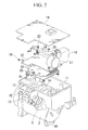
FIG. 2] Fig. 2 is an exploded perspective view illustrating the inverter-integrated electric compressor shown inFig. 1 . - [
FIG. 3] Fig. 3 is a plan view illustrating a connection portion of a busbar and an enameled wire of a coil according to the first embodiment of the present invention. - [
FIG. 4] Fig. 4 is a partially enlarged perspective view illustrating a connection portion of a busbar and an enameled wire of a coil shown inFig. 3 . - [
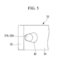
FIG. 5] Fig. 5 is a partially enlarged plan view illustrating a connection portion of a busbar and an enameled wire of a coil according to a second embodiment of the present invention. -
- 1:
- inverter-integrated electric compressor
- 2:
- housing
- 11:
- inverter housing portion
- 17:
- inductor (coil)
- 18:
- inverter device
- 23:
- busbar assembly
- 26:
- capacitor (coil)
- 27, 28:
- enameled wire
- 27A, 28A:
- enameled wire end portion
- 33:
- busbar
- 34:
- external connection portion
- 35:
- bent surface
- 35A:
- welding point
- 36, 46:
- through hole
- Hereinafter, embodiments of the present invention will be described with reference to the drawings.
- Hereinafter, a first embodiment of the present invention will be described with reference to
Fig. 1 to Fig. 4 . -
Fig. 1 is an external side view illustrating an inverter-integrated electric compressor 1 according to the first embodiment of the present invention. The inverter-integrated electric compressor 1 includes ahousing 2 that forms an outer shell of the inverter-integrated electric compressor 1. Thehousing 2 includes amotor housing 3 that accommodates an electric motor (not shown) and acompressor housing 4 that accommodates a compressor (not shown). Themotor housing 3 and thecompressor housing 4 are integrally fastened and fixed through abolt 5. Themotor housing 3 and thecompressor housing 4 are formed by aluminum die-casting. - The electric motor (not shown) and the compressor (not shown) accommodated and installed in the
motor housing 3 and thecompressor housing 4 are connected with each other through a motor shaft. The compressor is driven by rotation of the electric motor. At a rear end side (right side inFig. 1 ) of themotor housing 3, aninlet port 6 is provided. Low-pressure refrigerant gas introduced from theinlet port 6 into themotor housing 3 passes through around the electric motor, and sucked and compressed by the compressor. The high-temperature and high-pressure refrigerant gas compressed by the compressor is discharged into thecompressor housing 4, and discharged to outside from an outlet port 7 provided at a front end side (left side inFig. 1 ) of thecompressor housing 4. - The
housing 2 includes mountingfeet Fig. 1 ) of themotor housing 3, a lower part of the front end side (left side inFig. 1 ) of thecompressor housing 4, and an upper side of thecompressor housing 4. With mountingfeet - Further, on upper part of the periphery of the
motor housing 3, a box-shapedinverter housing portion 11 is integrally formed. As shown inFig. 2 , theinverter housing portion 11 has a box structure that the upper surface is opened and surrounded by a wall having a predetermined height. On a side surface of theinverter housing portion 11, two powercable outlet ports 12 are provided. In theinverter housing portion 11, a motorterminal mounting hole 13 and a metalplate radiation surface 14 are provided. Further, a direct current power P-N terminal that is connected with a power cable (not shown), a metal plate installation boss portion, a CPU board installation boss portion, and the like are provided. Theinverter housing portion 11 houses amotor terminal 15 that is to be mounted on the motorterminal mounting hole 13, ahead condenser 16, aninductor 17, aninverter device 18, and the like. The upper surface of theinverter housing portion 11 is covered with alid member 19 by screwing thelid member 19. - As shown in
Fig. 2 , theinverter device 18 includes ametal plate 20, apower board 21, aCPU board 22, and abusbar assembly 23. Themetal plate 20 is made of an aluminum alloy, and fixed and installed in boss portions or the like at four corners so that themetal plate 20 contacts with theradiation surface 14 of theinverter housing portion 11 to function as a heat sink. Thepower board 21 includes a power system control circuit that operates a semiconductor switching device for power (insulated gate bipolar transistor, hereinafter, referred to as IGBT) (not shown) that is installed on themetal plate 20, and installed on boss parts on themetal plate 20. TheCPU board 22 includes a circuit that has an element that operates at low voltage of a CPU or the like and is fixed and installed in boss portions or the like at four corners. Thebusbar assembly 23 includes busbars that function as wirings for theinverter device 18 and the busbars are integrally formed by insert forming using a resin of an insulating material. - The
busbar assembly 23 is formed as a component such that the plurality of busbars such as a P-N busbar that connects the IGBT (not shown) with a direct current power P-N terminal, a U-V-W busbar that connects the IGBT with themotor terminal 15 are integrally formed using aninsert resin 24. Thebusbar assembly 23 is formed to have an L-shape to be opposite to the direct current power P-N terminal and themotor terminal 15, and integrally fixed onto thepower board 21 using ascrew 25 along adjacent two sides of thepower board 21. - The
busbar assembly 23 functions as the power supply line as described above and abusbar 33 functions as a ground line of thebusbar assembly 23. In thebusbar 33, as shown inFig. 3 , to remove electric noise, both ends of enameled wires 27 and 28 of the coils such as theinductor 17, the capacitor 26, and the like are welded and connected by micro resistance welding or the like. - To end portions of
external connection portions 34 in thebusbar 33, as shown inFig. 4 ,bent surfaces 35 that are bent upward are formed. At a welding point 35A on an inner surface side of thebent surface 35, anend portion 27A of the enameled wire 27 or anend portion 28A of the enameled wire 28 is positioned and welded. - On the
external connection portion 34 described above, on the inside of a base of thebent surface 35, a through hole 36 through which theend portion 27A of the enameled wire 27 or theend portion 28A of the enameled wire 28 passes is provided. By passing theend portion 27A of the enameled wire 27 or theend portion 28A of the enameled wire 28 through the through hole 36, theend portion bent surface 35. - With respect to the
external connection portions 34 of thebusbar 33, inFig. 3 , at a right end part of thebusbar 33, a pair of theexternal connection portions 34 for theinductor 17 is provided, and at a left end part, a pair of theexternal connection portions 34 for the capacitor 26 is provided. The bent surfaces 35 of theexternal connection portions 34 provided at the plurality of positions are positioned such that the welding surfaces, that is, the inner surfaces of the bent surfaces face the same direction (in the present embodiment, the upper side direction inFig. 3 ). - By the above-described structure, according to the present embodiment, the following effects can be obtained.
- In the installation of the
inverter device 18 in theinverter housing portion 11, themetal plate 20 is installed and fixed onto theradiation surface 14 in a state that the IGBT (not shown), thepower board 21, and the like are subassembled on themetal plate 20. Here, onto thepower board 21, thebusbar assembly 23 is integrally fixed. Onto thebusbar 33 of thebusbar assembly 23, the coils such as theinductor 17, the capacitor 26, and the like installed in theinverter housing portion 11 in advance are welded and connected. - In the welding connection, as shown in
Figs. 3 and 4 , theend portions inductor 17, the capacitor 26, and the like are passed through the through holes 36 that are provided on theexternal connection portions 34 of thebusbar 33. Then, theend portions bent surfaces 35 that are the welding surfaces. Accordingly, by moving a welding machine (not shown) in the state and welding theend portions bent surfaces 35 of thebusbar 33 by micro resistance welding or the like, the enameled wires 27 and 28 of the coils can be accurately and firmly welded and connected to the predetermined welding points 35A of thebusbar 33. - As described above, since it is possible to accurately and readily position the
end portions busbar 33, the accuracy and reliability in the welding of the welding points and the end portions can be improved. Further, the production process of the welding can be reduced. - Accordingly, it is possible to improve the productivity and the product quality, reduce the cost, and the high-quality and highly reliable inverter-integrated electric compressor 1 can be manufactured at low cost.
- Further, the pair of the
bent surface 35 for welding and connecting theend portions busbar 33 side, and the pairs of thebent surfaces 35 for welding and connecting theend portions busbar 33 side face the same direction. Accordingly, the structure of the welding machine side can be simplified. Further, if the welding machine is moved, only by moving the welding machine in an X-Y direction, the welding can be performed at the plurality of points, and the movement can be simplified. Accordingly, the time necessary for the welding can be reduced as much as possible, and the efficiency in the welding operation can be increased and the productivity can be improved. Further, even if it is required to position the plurality of the coils separately due to a packaging restriction, it is possible to readily deal with the problem. - Now, a second embodiment of the present invention will be described with reference to
Fig. 5 . - The second embodiment differs in a structure of the through hole provided in the
external connection portion 34 of thebusbar 33 from that in the first embodiment described above. The other structures are similar to those in the first embodiment. Accordingly, their descriptions are omitted. - As shown in
Fig. 5 , a throughhole 46 has a deformed shape to have a larger diameter at a part away from thebent surface 35. The closer to the base portion of thebent surface 35, the more the part becomes tapered. - As described above, by the formation of the through
hole 46 having the large diameter at the part away from thebent surface 35 and tapering the hole gradually to the base portion of thebent surface 35, the pass-through operation can be facilitated by inserting theend portion 27A of the enameled wire 27 or theend portion 28A of the enameled wire 28 into the throughhole 46 from the large-diameter portion. Further, by moving theend portion 27A of the enameled wire 27 or theend portion 28A of the enameled wire 28 passed through the throughhole 46 to the tapered portion side, the positioning with respect to the welding point 35A of thebent surface 35 can be automatically performed, and the accuracy can be ensured. Accordingly, the welding operation can be further facilitated and the productivity can be improved. Further, the accuracy and reliability in the welding can be ensured. - It is to be understood that the present invention is not limited to the above-described embodiments, but various modifications can be made without departing from the spirit of the invention. For example, in the welding of the
busbar 33 and the enameled wires 27 and 28, thebusbar 33 is formed by plating copper with tin, and the enameled wires 27 and 28 are formed by coating copper wires with enamel. However, if thebusbar 33 and the wire 27 or 28 can be welded together, the welding method is not limited to the micro resistance welding, but any welding method may be employed.
Claims (5)
- A busbar connection structure for closely contacting, welding and connecting an enameled wire end portion of a coil onto an external connection bent surface formed on a busbar,
wherein a through hole through which the end portion of the enameled wire passes is formed on the inside of a base portion of the bent surface of the busbar, and
the end portion of the enameled wire is passed through the through hole, positioned onto a welding point of the bent surface, and welded and connected onto the bent surface. - The busbar connection structure according to Claim 1,
wherein a pair of the bent surfaces is provided to the busbar to weld and connect both end portions of the enameled wire of the coil, and the pair of the bent surfaces is provided to face a same direction. - The busbar connection structure according to Claim 1 or 2, wherein a plurality of coils are connected to the busbar, a plurality of the pair of the bent surfaces for welding and connecting the both end portions of the enameled wires of the coils is provided at a plurality of positions on the busbar, and the pairs of the bent surfaces provided at the plurality of positions face the same direction.
- The busbar connection structure according to any one of Claims 1 to 3, wherein the through hole has a shape formed to have a large diameter at a part away from the bent surface and taper the hole gradually to the base portion of the bent surface.
- An inverter-integrated electric compressor comprising:an inverter housing portion provided on a periphery of a housing that accommodates an electric compressor, andan inverter device installed in the inverter housing portion, the inverter device which converts a direct current power into a three-phase alternating current power and supplies the power to an electric motor,wherein the inverter device includes a busbar assembly formed by integrating a plurality of busbars that function as wirings of the inverter device using a insulating material, and at least one coil that is welded and connected to the busbar, and a welding structure of the busbar and an enameled wire of the coil is the busbar connection structure according to any one of Claims 1 to 4.
Applications Claiming Priority (2)
| Application Number | Priority Date | Filing Date | Title |
|---|---|---|---|
| JP2007022744A JP5054991B2 (en) | 2007-02-01 | 2007-02-01 | Busbar connection structure and inverter-integrated electric compressor |
| PCT/JP2008/050576 WO2008093544A1 (en) | 2007-02-01 | 2008-01-18 | Bus-bar connecting structure, and inverter-integrated type electric compressor |
Publications (3)
| Publication Number | Publication Date |
|---|---|
| EP2058925A1 true EP2058925A1 (en) | 2009-05-13 |
| EP2058925A4 EP2058925A4 (en) | 2012-07-18 |
| EP2058925B1 EP2058925B1 (en) | 2014-08-20 |
Family
ID=39673858
Family Applications (1)
| Application Number | Title | Priority Date | Filing Date |
|---|---|---|---|
| EP08703426.0A Not-in-force EP2058925B1 (en) | 2007-02-01 | 2008-01-18 | Bus-bar connecting structure, and inverter-integrated type electric compressor |
Country Status (5)
| Country | Link |
|---|---|
| US (1) | US8253020B2 (en) |
| EP (1) | EP2058925B1 (en) |
| JP (1) | JP5054991B2 (en) |
| CN (1) | CN101542873A (en) |
| WO (1) | WO2008093544A1 (en) |
Cited By (1)
| Publication number | Priority date | Publication date | Assignee | Title |
|---|---|---|---|---|
| EP2461035A4 (en) * | 2009-07-30 | 2017-08-30 | Mitsubishi Heavy Industries, Ltd. | Inverter-integrated motor-driven compressor |
Families Citing this family (21)
| Publication number | Priority date | Publication date | Assignee | Title |
|---|---|---|---|---|
| JP5254587B2 (en) * | 2007-10-05 | 2013-08-07 | 三菱重工業株式会社 | Inverter-integrated electric compressor |
| JP5107114B2 (en) * | 2008-03-28 | 2012-12-26 | 三菱重工業株式会社 | Inverter-integrated electric compressor |
| JP5138551B2 (en) * | 2008-11-06 | 2013-02-06 | サンデン株式会社 | Inverter-integrated electric compressor |
| JP2010144694A (en) * | 2008-12-22 | 2010-07-01 | Mitsubishi Heavy Ind Ltd | Inverter integrated electric compressor |
| JP4898931B2 (en) | 2010-02-10 | 2012-03-21 | 三菱重工業株式会社 | Inverter-integrated electric compressor |
| WO2013132584A1 (en) * | 2012-03-06 | 2013-09-12 | 三菱電機株式会社 | Electric power steering drive device |
| JP5934618B2 (en) * | 2012-09-14 | 2016-06-15 | 矢崎総業株式会社 | Terminal fitting |
| JP6037809B2 (en) * | 2012-12-07 | 2016-12-07 | 三菱重工業株式会社 | Inverter-integrated electric compressor |
| JP6195453B2 (en) * | 2013-02-20 | 2017-09-13 | 三菱重工オートモーティブサーマルシステムズ株式会社 | Inverter-integrated electric compressor |
| CN103521938B (en) * | 2013-10-11 | 2015-12-23 | 重庆万力联兴实业(集团)有限公司 | The welding procedure of electric fuel punp electrode plug and enamel-covered wire |
| US9509196B2 (en) * | 2013-12-12 | 2016-11-29 | Nidec Corporation | Motor |
| JP6767761B2 (en) * | 2016-03-24 | 2020-10-14 | サンデン・オートモーティブコンポーネント株式会社 | Inverter integrated electric compressor |
| CN109478731B (en) * | 2016-08-23 | 2020-03-03 | 日本精工株式会社 | Terminal connection member and terminal connection structure between control device and motor using the same |
| JP2018129926A (en) * | 2017-02-08 | 2018-08-16 | シナノケンシ株式会社 | Motor and manufacturing method of the same |
| US10717401B2 (en) | 2017-04-21 | 2020-07-21 | Ford Global Technologies, Llc | Terminal block assembly for electrified vehicles |
| JP6708190B2 (en) * | 2017-09-05 | 2020-06-10 | 株式会社デンソー | Joining structure of semiconductor module and joining method |
| JP2020149827A (en) * | 2019-03-13 | 2020-09-17 | 豊田鉄工株式会社 | Heat dissipation structure of bus bar |
| JP7342766B2 (en) * | 2020-03-31 | 2023-09-12 | 株式会社豊田自動織機 | electric compressor |
| DE102021203954A1 (en) * | 2020-06-24 | 2021-12-30 | Robert Bosch Gesellschaft mit beschränkter Haftung | Stator of an electrical machine |
| JP2022015430A (en) * | 2020-07-09 | 2022-01-21 | 日立Astemo株式会社 | Terminal connection structure, manufacturing method of terminal connection structure, and power conversion device |
| JP7435520B2 (en) * | 2021-03-29 | 2024-02-21 | 株式会社豊田自動織機 | electric compressor |
Family Cites Families (11)
| Publication number | Priority date | Publication date | Assignee | Title |
|---|---|---|---|---|
| JPS4611160Y1 (en) * | 1968-04-05 | 1971-04-19 | ||
| JPH0645258U (en) * | 1992-11-25 | 1994-06-14 | 株式会社東海理化電機製作所 | Terminal and wire connection structure |
| US5338992A (en) * | 1993-07-15 | 1994-08-16 | Tsai Wen Cheng | Coil structure of ceiling fan motor |
| DE29505107U1 (en) * | 1995-03-25 | 1995-05-18 | Weidmüller Interface GmbH & Co, 32760 Detmold | Track with connector pin |
| JPH11220823A (en) | 1998-01-30 | 1999-08-10 | Harness Syst Tech Res Ltd | Busbar structure of electrical junction box |
| JP3760887B2 (en) * | 2002-04-26 | 2006-03-29 | 株式会社デンソー | Inverter integrated motor for vehicles |
| EP1363026A3 (en) * | 2002-04-26 | 2004-09-01 | Denso Corporation | Invertor integrated motor for an automotive vehicle |
| DE20320643U1 (en) | 2002-04-26 | 2004-12-23 | Denso Corp., Kariya | 2002JP127299egrated motor for driving air conditioner of automotive vehicle, has bus-bar integrated plate set at radial outer side of modules to extend to tangential direction of motor, in which gap is formed between plate and motor |
| JP2004190547A (en) | 2002-12-10 | 2004-07-08 | Denso Corp | Inverter-integrated electric compressor and method of assembling the same |
| JP3827158B2 (en) * | 2003-01-21 | 2006-09-27 | 株式会社デンソー | Inverter-integrated electric compressor with shunt resistor |
| JP4259452B2 (en) * | 2004-10-26 | 2009-04-30 | 住友電装株式会社 | connector |
-
2007
- 2007-02-01 JP JP2007022744A patent/JP5054991B2/en not_active Expired - Fee Related
-
2008
- 2008-01-18 WO PCT/JP2008/050576 patent/WO2008093544A1/en not_active Ceased
- 2008-01-18 CN CNA2008800004626A patent/CN101542873A/en active Pending
- 2008-01-18 EP EP08703426.0A patent/EP2058925B1/en not_active Not-in-force
- 2008-01-18 US US11/989,862 patent/US8253020B2/en not_active Expired - Fee Related
Cited By (1)
| Publication number | Priority date | Publication date | Assignee | Title |
|---|---|---|---|---|
| EP2461035A4 (en) * | 2009-07-30 | 2017-08-30 | Mitsubishi Heavy Industries, Ltd. | Inverter-integrated motor-driven compressor |
Also Published As
| Publication number | Publication date |
|---|---|
| JP5054991B2 (en) | 2012-10-24 |
| US8253020B2 (en) | 2012-08-28 |
| EP2058925B1 (en) | 2014-08-20 |
| US20090255704A1 (en) | 2009-10-15 |
| EP2058925A4 (en) | 2012-07-18 |
| CN101542873A (en) | 2009-09-23 |
| JP2008193767A (en) | 2008-08-21 |
| WO2008093544A1 (en) | 2008-08-07 |
Similar Documents
| Publication | Publication Date | Title |
|---|---|---|
| EP2058925B1 (en) | Bus-bar connecting structure, and inverter-integrated type electric compressor | |
| JP4764365B2 (en) | Inverter-integrated electric compressor | |
| JP4719134B2 (en) | Inverter-integrated electric compressor | |
| JP6444605B2 (en) | Inverter-integrated electric compressor | |
| JP5107013B2 (en) | Inverter-integrated electric compressor | |
| US9267502B2 (en) | Motor-driven compressor | |
| CN104052197B (en) | Electronic-controlled installation | |
| US9590553B2 (en) | Power conversion apparatus and electric power steering device | |
| US8785777B2 (en) | Actuator control device, and method of manufacturing circuit device in actuator control device | |
| CN102333953B (en) | Inverter-integrated motor-driven compressor | |
| WO2009084324A1 (en) | Inverter-integrated electric compressor | |
| US20150163961A1 (en) | Power Conversion Apparatus | |
| JP2008128142A5 (en) | ||
| CN105317655A (en) | Electric compressor | |
| JP2009148011A (en) | Bus bar assembly and electric compressor integrating inverter using it | |
| WO2018051718A1 (en) | Inverter-integrated electric compressor and method for manufacturing same | |
| US12107479B2 (en) | Motor housing cover arrangement of an electric motor with components surrounded by molding compound | |
| JP5683290B2 (en) | Inter-board connection terminal, inverter using the same, and electric compressor | |
| JP5536172B2 (en) | Inverter-integrated electric compressor | |
| JP6932219B1 (en) | Power converter | |
| JP7526995B2 (en) | Coil block connection structure for linear motors | |
| CN219678304U (en) | Support insulator and power conversion device | |
| CN108987950B (en) | Terminal board for fixing electric wire and method for fixing electric wire on terminal board | |
| WO2025263564A1 (en) | Inverter device and inverter-integrated electric compressor provided with same |
Legal Events
| Date | Code | Title | Description |
|---|---|---|---|
| PUAI | Public reference made under article 153(3) epc to a published international application that has entered the european phase |
Free format text: ORIGINAL CODE: 0009012 |
|
| 17P | Request for examination filed |
Effective date: 20081215 |
|
| AK | Designated contracting states |
Kind code of ref document: A1 Designated state(s): AT BE BG CH CY CZ DE DK EE ES FI FR GB GR HR HU IE IS IT LI LT LU LV MC MT NL NO PL PT RO SE SI SK TR |
|
| AX | Request for extension of the european patent |
Extension state: AL BA MK RS |
|
| DAX | Request for extension of the european patent (deleted) | ||
| RBV | Designated contracting states (corrected) |
Designated state(s): DE FR GB |
|
| A4 | Supplementary search report drawn up and despatched |
Effective date: 20120614 |
|
| RIC1 | Information provided on ipc code assigned before grant |
Ipc: H01R 4/58 20060101ALI20120608BHEP Ipc: H02K 5/22 20060101AFI20120608BHEP Ipc: F04B 39/00 20060101ALI20120608BHEP Ipc: H01R 4/02 20060101ALI20120608BHEP |
|
| GRAP | Despatch of communication of intention to grant a patent |
Free format text: ORIGINAL CODE: EPIDOSNIGR1 |
|
| INTG | Intention to grant announced |
Effective date: 20140321 |
|
| RIN1 | Information on inventor provided before grant (corrected) |
Inventor name: TAKASHIGE, TAKAYUKI Inventor name: TAKAI, ATSUSHI Inventor name: NIWA, KAZUKI Inventor name: HATTORI, MAKOTO |
|
| GRAS | Grant fee paid |
Free format text: ORIGINAL CODE: EPIDOSNIGR3 |
|
| GRAA | (expected) grant |
Free format text: ORIGINAL CODE: 0009210 |
|
| AK | Designated contracting states |
Kind code of ref document: B1 Designated state(s): DE FR GB |
|
| REG | Reference to a national code |
Ref country code: GB Ref legal event code: FG4D |
|
| REG | Reference to a national code |
Ref country code: DE Ref legal event code: R096 Ref document number: 602008033949 Country of ref document: DE Effective date: 20141002 |
|
| REG | Reference to a national code |
Ref country code: DE Ref legal event code: R097 Ref document number: 602008033949 Country of ref document: DE |
|
| PLBE | No opposition filed within time limit |
Free format text: ORIGINAL CODE: 0009261 |
|
| STAA | Information on the status of an ep patent application or granted ep patent |
Free format text: STATUS: NO OPPOSITION FILED WITHIN TIME LIMIT |
|
| 26N | No opposition filed |
Effective date: 20150521 |
|
| GBPC | Gb: european patent ceased through non-payment of renewal fee |
Effective date: 20150118 |
|
| PG25 | Lapsed in a contracting state [announced via postgrant information from national office to epo] |
Ref country code: GB Free format text: LAPSE BECAUSE OF NON-PAYMENT OF DUE FEES Effective date: 20150118 |
|
| REG | Reference to a national code |
Ref country code: FR Ref legal event code: ST Effective date: 20150930 |
|
| PG25 | Lapsed in a contracting state [announced via postgrant information from national office to epo] |
Ref country code: FR Free format text: LAPSE BECAUSE OF NON-PAYMENT OF DUE FEES Effective date: 20150202 |
|
| PGFP | Annual fee paid to national office [announced via postgrant information from national office to epo] |
Ref country code: DE Payment date: 20200107 Year of fee payment: 13 |
|
| REG | Reference to a national code |
Ref country code: DE Ref legal event code: R119 Ref document number: 602008033949 Country of ref document: DE |
|
| PG25 | Lapsed in a contracting state [announced via postgrant information from national office to epo] |
Ref country code: DE Free format text: LAPSE BECAUSE OF NON-PAYMENT OF DUE FEES Effective date: 20210803 |