EP2058906A1 - Waterproof plug for connector, waterproof connector comprising the same and method of attaching the same - Google Patents
Waterproof plug for connector, waterproof connector comprising the same and method of attaching the same Download PDFInfo
- Publication number
- EP2058906A1 EP2058906A1 EP08168307A EP08168307A EP2058906A1 EP 2058906 A1 EP2058906 A1 EP 2058906A1 EP 08168307 A EP08168307 A EP 08168307A EP 08168307 A EP08168307 A EP 08168307A EP 2058906 A1 EP2058906 A1 EP 2058906A1
- Authority
- EP
- European Patent Office
- Prior art keywords
- housing
- waterproof plug
- elements
- waterproof
- connector
- Prior art date
- Legal status (The legal status is an assumption and is not a legal conclusion. Google has not performed a legal analysis and makes no representation as to the accuracy of the status listed.)
- Granted
Links
- 238000000034 method Methods 0.000 title claims abstract description 17
- 238000007789 sealing Methods 0.000 claims abstract description 71
- 230000002093 peripheral effect Effects 0.000 claims abstract description 22
- 238000003780 insertion Methods 0.000 claims description 21
- 230000037431 insertion Effects 0.000 claims description 21
- 230000008878 coupling Effects 0.000 claims description 4
- 238000010168 coupling process Methods 0.000 claims description 4
- 238000005859 coupling reaction Methods 0.000 claims description 4
- 239000003381 stabilizer Substances 0.000 description 6
- 239000013013 elastic material Substances 0.000 description 2
- 229920001971 elastomer Polymers 0.000 description 2
- -1 for example Substances 0.000 description 2
- 239000007788 liquid Substances 0.000 description 2
- 229920000800 acrylic rubber Polymers 0.000 description 1
- 238000005452 bending Methods 0.000 description 1
- 238000010276 construction Methods 0.000 description 1
- 230000000694 effects Effects 0.000 description 1
- 239000003822 epoxy resin Substances 0.000 description 1
- 239000000463 material Substances 0.000 description 1
- 239000002184 metal Substances 0.000 description 1
- 238000012986 modification Methods 0.000 description 1
- 230000004048 modification Effects 0.000 description 1
- 239000004033 plastic Substances 0.000 description 1
- 229920000058 polyacrylate Polymers 0.000 description 1
- 229920000647 polyepoxide Polymers 0.000 description 1
- 229920002379 silicone rubber Polymers 0.000 description 1
Images



Classifications
-
- H—ELECTRICITY
- H01—ELECTRIC ELEMENTS
- H01R—ELECTRICALLY-CONDUCTIVE CONNECTIONS; STRUCTURAL ASSOCIATIONS OF A PLURALITY OF MUTUALLY-INSULATED ELECTRICAL CONNECTING ELEMENTS; COUPLING DEVICES; CURRENT COLLECTORS
- H01R13/00—Details of coupling devices of the kinds covered by groups H01R12/70 or H01R24/00 - H01R33/00
- H01R13/46—Bases; Cases
- H01R13/52—Dustproof, splashproof, drip-proof, waterproof, or flameproof cases
- H01R13/5202—Sealing means between parts of housing or between housing part and a wall, e.g. sealing rings
-
- H—ELECTRICITY
- H01—ELECTRIC ELEMENTS
- H01R—ELECTRICALLY-CONDUCTIVE CONNECTIONS; STRUCTURAL ASSOCIATIONS OF A PLURALITY OF MUTUALLY-INSULATED ELECTRICAL CONNECTING ELEMENTS; COUPLING DEVICES; CURRENT COLLECTORS
- H01R13/00—Details of coupling devices of the kinds covered by groups H01R12/70 or H01R24/00 - H01R33/00
- H01R13/46—Bases; Cases
- H01R13/52—Dustproof, splashproof, drip-proof, waterproof, or flameproof cases
- H01R13/5205—Sealing means between cable and housing, e.g. grommet
- H01R13/5208—Sealing means between cable and housing, e.g. grommet having at least two cable receiving openings
Definitions
- the present invention relates to a waterproof plug for a connector and a waterproof connector comprising the same, in more particular, to a waterproof plug for a connector for sealing a housing which houses a terminal, a waterproof connector comprising the same and a method of attaching the same.
- a conventional waterproof connector comprising a terminal fixed at an edge of an electric cable, a housing for housing this terminal in the inside thereof, a seal member as a waterproof plug for sealing (liquid seal) this housing and a holder for holding the electric cable by positioning the seal member inside the housing (for example, disclosed by JP-A 2005-129460 ).
- the terminal has a projection (a stabilizer) for preventing a reverse insertion and is locked inside the housing.
- the housing has a locking portion for locking the terminal and a guide for guiding the stabilizer, and is configured to open on a cable insertion side and an external terminal connection side for housing a portion of the electric cable, the seal member and the holder with the terminal in the inside thereof.
- the seal member has a through hole allowing the press-fitting of the terminal and the electric cable, is housed in a state of being pressed against the inside of the housing and is entirely formed of a soft elastic material such as, for example, rubber or the like.
- the holder has a through hole letting through the electric cable and is mounted inside the housing. And it is configured to be positioned at a predetermined position by pressing the seal member from the cable insertion side to the external terminal connection side when inserting the holder into the housing.
- the waterproof connector is attached by inserting the seal member into the housing from the opening on the cable insertion side so as to be placed at a predetermined position, sequentially placing the holder on the cable insertion side of the seal member, subsequently passing the electric cable through by inserting the terminal into a through hole of the holder and that of the seal member, and pressing the seal member in a thickness direction thereof by moving the holder from the cable insertion side to the external terminal connection side after locking the terminal to the locking portion inside the housing.
- the seal member when the seal member receives pressure from the holder, the seal member is compressed in the thickness direction thereof and expands in a direction to press against an inner surface of the housing, thereby sealing the opening of the housing (an opening on the cable insertion side).
- the present invention seeks to provide for a waterproof plug, waterproof connector and related method having advantages over known such plugs, connectors and methods.
- a waterproof plug for a connector comprising:
- the invention advantageously provides for a waterproof plug for a connector which can prevent damage to a seal member resulting that good sealing performance is obtained, a waterproof connector comprising the same and a method of attaching the same.
- the at least two elements have first sealing surfaces fitting to an inner surface of the housing, second sealing surfaces fitting to the outer peripheral surfaces of the electric cable and third sealing surfaces connecting to the second sealing surfaces.
- the first sealing surfaces of the at least two elements can have projections pressing against the inner surface of the housing.
- the second sealing surfaces of the at least two elements can be formed of inner peripheral surfaces having a curvature substantially same as that of the outer peripheral surface of the electric cables.
- the third sealing surfaces of the at least two elements can be formed of substantially flat surfaces pressing against each other in a state that the seal member is housed in the housing.
- the third sealing surfaces of the at least two elements can be formed of concave-convex surfaces in a corrugated shape.
- a waterproof plug for a connector for sealing a housing to house terminals fixed at edges of electric cables comprising:
- the hinge can be formed by a single member having a through hole letting through the electric cable.
- a waterproof connector comprising:
- a waterproof connector including terminals fixed at an edges of electric cables, a housing to house the terminals in the inside thereof and a waterproof plug for a connector having two elements for sealing the housing, the method comprising:
- FIG.1 is an exploded perspective view shown for explaining the entire waterproof connector in a preferred embodiment according to the present invention.
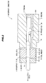
- FIG.2 is a vertical cross-sectional view shown for explaining the entire waterproof connector in the preferred embodiment according to the present invention.
- FIGS.3A and 3B are perspective views shown for explaining an attached state of the electric cable into the waterproof plug of the waterproof connector in the preferred embodiment according to the present invention, wherein FIG.3A shows a developed state of the waterproof plug and FIG.3B shows a folded state of the waterproof plug, respectively.
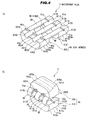
- FIGS.4A and 4B are perspective views showing the waterproof plug of the waterproof connector in the preferred embodiment according to the present invention wherein FIG.4A shows a developed state of the waterproof plug and FIG.4B shows a folded state of the waterproof plug, respectively.
- a waterproof connector indicated by a reference numeral 1 is schematically configured to comprise terminals 2,2 crimpingly fixed at edges of electrical cables 100,100 respectively, a housing 3 for housing these terminals 2,2 in the inside thereof, a waterproof plug 4 for sealing (liquid seal) this housing 3 and a holder 5 for holding the electrical cables 100,100 by positioning this waterproof plug 4 inside the housing 3.
- the respective terminals 2,2 have projections (stabilizers) 2 A, 2 A for preventing a reverse insertion and are locked inside the housing 3.
- the entire terminal 2 is formed of a conductive member such as metal or the like.
- the housing 3 has a housing space 3 A opening on a cable insertion side and an external terminal connection side for housing a portion of the electric cables 100,100, the waterproof plug 4 and the holder 5 with the terminals 2,2, and is entirely formed of an insulating member such as an epoxy resin or the like.
- Locking portions 3B,3B for locking the terminals 2,2 and guides 3 C, 3 C for guiding the stabilizers 2 A, 2 A are arranged in the housing space 3 A of the housing 3 .
- the waterproof plug 4 comprises a seal member 4A and hinges 4B,4B ⁇ (three hinges in this embodiment), and is housed on the cable insertion side of the housing space 3A in the housing 3.
- the seal member 4 A has a pair of elements 40 A and 41 A holding the electric cables 100,100 sandwiching from both sides and tightly contacting with the outer peripheral surfaces thereof, and is housed in a state of being pressed against the inside of the housing 3.
- a soft elastic material composed of plastic rubber such as, for example, silicon rubber, acrylic rubber or the like is used.
- the elements 40 A and 41 A have first sealing surfaces 400 A and 410 A fitting to the inner surface of the housing 3, second sealing surfaces 401 A and 411 A fitting to the outer peripheral surfaces of the electric cables 100,100 respectively and third sealing surfaces 402 A and 412 A connecting to the second sealing surfaces 401 A and 411 A respectively, and are entirely formed by curved-surface bodies. Two of second sealing surfaces 401 A and two of second sealing surfaces 411 A are arranged in the elements 40 A and 41 A respectively, and three of third sealing surfaces 402 A and three of third sealing surfaces 412 A are arranged in the elements 40 A and 41 A respectively.
- the element 40 A is provided with convex portions 40 a, 40 a ⁇ (three convex portions in this embodiment) located at a portion adjacent to the hinges 4B,4B and projecting from the third sealing surfaces 402 A, 402 A.
- Concave portions 41 a, 41 a ⁇ for engaging with the convex portions 40 a, 40 a ⁇ respectively are provided on the element 41 A.
- One element 40 A is locked to another element 41 A in a state that the convex portions 40 a, 40 a ⁇ are engaged with the concave portions 41 a, 41 a ⁇ .
- the first sealing surfaces 400 A and 410 A are formed of two substantially flat surfaces pressing against the housing 3 and smooth curved surfaces intermediating between these two flat surfaces in a state that the seal member 4 A is housed in the housing 3 .
- the second sealing surfaces 401 A and 411 A are formed of inner peripheral surfaces having curvature substantially same as that of outer peripheral surfaces of the electric cables 100,100. And the second sealing surfaces 401 A and 411 A are configured to press against each other via the electric cables 100,100 respectively in the state that the seal member 4 A is housed in the housing 3.
- the third sealing surfaces 402 A and 412 A are formed of substantially flat surfaces which face each other in a state that the seal member 4 A is folded. And the third sealing surfaces 402 A and 412 A are configured to press against each other in the state that the seal member 4 A is housed in the housing 3.
- the hinges 4B,4B are aligned in parallel in a width direction of the elements 40 A and 41 A at a predetermined interval, are integrally provided at edges of the cable insertion side of the elements 40 A and 41 A, and are entirely formed of a belt-like member having flexibility. And the hinges 4B,4B ⁇ are configured to couple the elements 40 A and 41 A so that the seal member 4 A is developable as shown in FIGS.3A and 4A as well as foldable as shown in FIGS.3B and 4B . Furthermore, as shown in FIG.1 , the hinges 4B,4B ⁇ are configured to form through holes 6,6 between the elements 40 A and 41 A for letting through the electric cables 100,100 by inserting the terminals 2,2. Namely the through holes 6,6 are arranged between two hinges 4B,4B adjacent to each other among the hinges 4B,4B ⁇ .
- the thickness of the hinges 4B,4B is set to be smaller than that of the elements 40 A and 41 A.
- a distance between the hinges 4B,4B adjacent to each other among the hinges 4B,4B ⁇ and a distance between the elements 40 A and 41 A are set so as to let through the electric cables 100,100 by inserting the terminals 2,2 into the through holes 6,6 respectively without damaging the waterproof plug 4 (the seal member 4 A and the hinges 4B,4B ⁇ ) in a state that the seal member 4 A is developed.
- the holder 5 has through holes 5 A, 5 A for letting through the electric cables 100 and is mounted by being inserted into the housing 3 .
- the holder 5 is configured to position the waterproof plug 4 , in which the electric cables 100,100 are preliminarily held from both sides by the elements 40 A and 41 A, and the terminals 2,2 preliminarily fixed at the edge of the electric cables 100,100 at a predetermined position by pressing from the cable insertion side to the external terminal connection side of the housing 3 when inserting the holder 5 into the housing 3.
- the holder 5 is provided with concave portions (not shown) for housing the hinges 4B,4B ⁇ in the state that the waterproof plug 4 is housed in the housing 3.
- FIG.5 is a flow chart shown for explaining a method of attaching the waterproof connector in the preferred embodiment according to the present invention.
- the electric cables are passed through the through holes 5 A, 5 A of the holder 5 respectively by inserting the terminals 2,2.
- the electric cables 100,100 are passed through the through holes 6,6 between the elements 40 A and 41 A by inserting the terminals 2,2 respectively, and are mounted by engaging with the second sealing surfaces 411 A, 411 A of the element 41 A.
- the seal member 4 A is folded by bending the hinges 4 B, 4 B ⁇ so as to engage the electric cables 100,100 with the second sealing surfaces 411 A, 411 A of the element 40 A and to lock the element 40 A to the element 41 A by engaging the convex portions 40 a, 40 a ⁇ of the element 40 A with the concave portions 41 a, 41 a ⁇ of the element 41 A respectively.
- the electric cables 100,100 are held from both sides by the elements 40 A and 41 A. Therefore, since the second sealing surfaces 411 A, 411 A of the element 41 A and the second sealing surfaces 401 A, 401 A of the element 40 A are pressed against each other via the electric cables 100,100, the second sealing surfaces 401 A, 401 A and the second sealing surfaces 411 A, 411 A tightly contact with the outer peripheral surfaces of the electric cables 100,100, respectively. Furthermore, the third sealing surfaces 412 A, 412 A of the element 41 A and the third sealing surfaces 402 A, 402 A of the element 40 A tightly contact with each other. As a result, the electric cables 100,100 are attached to (assembled with) the seal member 4 A (the waterproof plug 4 ) (step S 1 in FIG.5 ).
- the terminals 2,2 are inserted into the housing 3 from the cable insertion side toward the external terminal connection side so as to be arranged on the cable insertion side of the housing 3 (the housing space 3 A) by press-fitting of the waterproof plug 4 in which the electric cables 100,100 have been attached to the seal member 4 A in the step S 1 of FIG.5 .
- the waterproof plug 4 is arranged on the cable insertion side of the housing 3, the waterproof plug 4 is positioned in a surface direction orthogonal to a press-fitting direction thereof (step S 2 in FIG.5 ).
- the holder 5 is arranged at a predetermined position moved with the terminals 2,2 pressing the waterproof plug 4 from the from the cable insertion side toward the external terminal connection side by an insertion of the holder 5 into the housing 3.
- the waterproof plug 4 is moved while maintaining the state that the first sealing surface 400 A (the projections 400 a, 400 a ⁇ ) of the element 40 A and the first sealing surface 410 (the projections 410 a, 410 a ⁇ ) of the element 41 A are pressed against the inner surface of the housing 3.
- the terminals 2,2 are moved by guiding the stabilizer 2 A, 2 A by the guides 3 C, 3 C.
- the terminals 2,2 are attached inside the housing 3 by the locking of the locking portions 3 B, 3 B (step S 3 in FIG.5 ).
- the element 40 A and the element 41 A are coupled via the hinges 4 B, 4 B ⁇ , it is possible to form the waterproof plug 4 from a single piece similarly to the conventional plug.
- waterproof connector according to the present invention has been described based on the above preferred embodiment, the invention is not limited by the above preferred embodiment and it is possible to implement in various features without going beyond a scope of the concept. For example, following variations can be made.
- the hinges 4 B, 4 B are provided in parallel in a width direction of the element between the elements 40 A and 41 A and the through holes 6,6 are provided between two hinges 4 B, 4 B adjacent to each other among the hinges 4 B, 4 B ⁇
- the present invention is not limited thereto, a single hinge may be provided between a pair of elements providing a through hole to pass the electric cable through this hinge.
- the second sealing surfaces 401 A, 401 A of the element 40 A and the second sealing surfaces 411 A, 411 A of the element 41 A are formed of inner peripheral surfaces having a curvature substantially same as that of the outer peripheral surfaces of the electric cables 100,100
- opening shape formed by the second sealing surfaces of both elements may be, for example, a rectangular shape having an opening space smaller than a cross-section area of the electric cable.
- hinges 4 B, 4 B ⁇ are arranged at an edge of the cable insertion side of the elements 40 A and 41 A
- the present invention is not limited thereto, hinges may be arranged at an edge of the external terminal connection side (an edge opposite to the edge of the cable insertion side).
- the elements 40 A and 41 A are made in two tiers (one pair) in a thickness direction of the element in the folded state of the waterproof plug 4, the present invention is not limited thereto, the element may be made in three or more tiers. In this case, two elements adjacent to each other among multiple elements are coupled by the hinges so as to fold the seal member staggerly.
- each third sealing surface 402 A and 412 A are formed by flat surfaces having the convex portion 41 a and the concave portion 41 a respectively
- each third sealing surface may be formed by a concave-convex surface in a corrugated shape.
- each third sealing surface is formed by a concave-convex surface in a corrugated shape, and in addition to this, an outer peripheral surface of the covered portion in the electric cable may be formed by a concave-convex surface in a corrugated shape.
Landscapes
- Connector Housings Or Holding Contact Members (AREA)
Abstract
Description
- The present invention relates to a waterproof plug for a connector and a waterproof connector comprising the same, in more particular, to a waterproof plug for a connector for sealing a housing which houses a terminal, a waterproof connector comprising the same and a method of attaching the same.
- There is a conventional waterproof connector comprising a terminal fixed at an edge of an electric cable, a housing for housing this terminal in the inside thereof, a seal member as a waterproof plug for sealing (liquid seal) this housing and a holder for holding the electric cable by positioning the seal member inside the housing (for example, disclosed by
JP-A 2005-129460 - The terminal has a projection (a stabilizer) for preventing a reverse insertion and is locked inside the housing.
- The housing has a locking portion for locking the terminal and a guide for guiding the stabilizer, and is configured to open on a cable insertion side and an external terminal connection side for housing a portion of the electric cable, the seal member and the holder with the terminal in the inside thereof.
- The seal member has a through hole allowing the press-fitting of the terminal and the electric cable, is housed in a state of being pressed against the inside of the housing and is entirely formed of a soft elastic material such as, for example, rubber or the like.
- The holder has a through hole letting through the electric cable and is mounted inside the housing. And it is configured to be positioned at a predetermined position by pressing the seal member from the cable insertion side to the external terminal connection side when inserting the holder into the housing.
- From the above-mentioned configuration, the waterproof connector is attached by inserting the seal member into the housing from the opening on the cable insertion side so as to be placed at a predetermined position, sequentially placing the holder on the cable insertion side of the seal member, subsequently passing the electric cable through by inserting the terminal into a through hole of the holder and that of the seal member, and pressing the seal member in a thickness direction thereof by moving the holder from the cable insertion side to the external terminal connection side after locking the terminal to the locking portion inside the housing.
- In this case, when the seal member receives pressure from the holder, the seal member is compressed in the thickness direction thereof and expands in a direction to press against an inner surface of the housing, thereby sealing the opening of the housing (an opening on the cable insertion side).
- However, according to the conventional waterproof connector, there is a possibility that sealing performance deteriorates as the seal member is damaged by the stabilizer of the terminal which scratches an inner periphery of the through hole of the seal member when passing the electric cable through the through hole of the sealing member.
- The present invention seeks to provide for a waterproof plug, waterproof connector and related method having advantages over known such plugs, connectors and methods.
- According to the present invention, a waterproof plug for a connector, comprising:
- an elastically deformable seal member for sealing a housing which houses terminals fixed at edges of electric cables in the inside thereof,
- wherein the seal member is housed inside the housing by press-fitting, and has at least two elements holding the electric cables by sandwiching from both sides and tightly contacting with outer peripheral surfaces thereof.
- The invention advantageously provides for a waterproof plug for a connector which can prevent damage to a seal member resulting that good sealing performance is obtained, a waterproof connector comprising the same and a method of attaching the same.
- In the waterproof plug for a connector described above, the at least two elements have first sealing surfaces fitting to an inner surface of the housing, second sealing surfaces fitting to the outer peripheral surfaces of the electric cable and third sealing surfaces connecting to the second sealing surfaces.
- In the waterproof plug for a connector described above, the first sealing surfaces of the at least two elements can have projections pressing against the inner surface of the housing.
- In the waterproof plug for a connector described above, the second sealing surfaces of the at least two elements can be formed of inner peripheral surfaces having a curvature substantially same as that of the outer peripheral surface of the electric cables.
- In the waterproof plug for a connector described above, the third sealing surfaces of the at least two elements can be formed of substantially flat surfaces pressing against each other in a state that the seal member is housed in the housing.
- In the waterproof plug for a connector described above, the third sealing surfaces of the at least two elements can be formed of concave-convex surfaces in a corrugated shape.
- According to another aspect of the present invention, there is provided a waterproof plug for a connector for sealing a housing to house terminals fixed at edges of electric cables, comprising:
- an elastically deformable seal member housed in the housing by press-fitting, and having at least two elements which hold the electric cables by sandwiching from both sides and tightly contact with outer peripheral surfaces thereof; and
- hinges for coupling the at least two elements so that the seal member is developable and foldable, and for forming through holes between the at least two elements for letting through the electric cables by inserting the terminals.
- In the waterproof plug for a connector described above, the hinge can be formed by a single member having a through hole letting through the electric cable.
- According to another aspect of the present invention, there is provided a waterproof connector, comprising:
- terminals fixed at edges of an electric cables;
- a housing to house the terminals in the inside thereof; and
- a waterproof plug for a connector for sealing the housing,
- wherein the waterproof plug for a connector comprises;
- a seal member housed in the housing by press-fitting, and having at least two elements which hold the electric cables by sandwiching from both sides and tightly contact with outer peripheral surfaces thereof; and
- hinges for coupling the at least two elements so that the seal member is developable and foldable, and for forming through holes between the at least two elements for letting through the electric cables by inserting the terminals.
- According to yet another aspect of the present invention, there is provided a method of attaching a waterproof connector including terminals fixed at an edges of electric cables, a housing to house the terminals in the inside thereof and a waterproof plug for a connector having two elements for sealing the housing, the method comprising:
- a first step for attaching the electric cables to the waterproof plug for a connector, and
- a second step for inserting the terminals into the housing and positioning the waterproof plug for a connector by press fitting,
- wherein the electric cables are held from both sides by the two elements; and
- the two elements tightly contact with the outer peripheral surfaces of the electric cables when attaching the electric cables to the waterproof plug for a connector in the first step.
- As will therefore be appreciated, by way of the present invention it is possible to prevent damage to a seal member resulting that good sealing performance ca be obtained.
- The invention is described further hereinafter, by way of example only, with reference to the accompanying drawings in which:
-
FIG.1 is an exploded perspective view shown for explaining the entire waterproof connector in a preferred embodiment according to the present invention; -
FIG.2 is a vertical cross-sectional view shown for explaining the entire waterproof connector in the preferred embodiment according to the present invention; -
FIGS.3A and 3B are perspective views shown for explaining an attached state of the electric cable into the waterproof plug of the waterproof connector in the preferred embodiment according to the present invention; -
FIGS.4A and 4B are perspective views showing the waterproof plug of the waterproof connector in the preferred embodiment according to the present invention; and -
FIG.5 is a flow chart shown for explaining a method of attaching the waterproof connector in the preferred embodiment according to the present invention. -
FIG.1 is an exploded perspective view shown for explaining the entire waterproof connector in a preferred embodiment according to the present invention.FIG.2 is a vertical cross-sectional view shown for explaining the entire waterproof connector in the preferred embodiment according to the present invention.FIGS.3A and 3B are perspective views shown for explaining an attached state of the electric cable into the waterproof plug of the waterproof connector in the preferred embodiment according to the present invention, whereinFIG.3A shows a developed state of the waterproof plug andFIG.3B shows a folded state of the waterproof plug, respectively.FIGS.4A and 4B are perspective views showing the waterproof plug of the waterproof connector in the preferred embodiment according to the present invention whereinFIG.4A shows a developed state of the waterproof plug andFIG.4B shows a folded state of the waterproof plug, respectively. - In
FIG.1 andFIG.2 , a waterproof connector indicated by areference numeral 1 is schematically configured to compriseterminals housing 3 for housing theseterminals waterproof plug 4 for sealing (liquid seal) thishousing 3 and aholder 5 for holding the electrical cables 100,100 by positioning thiswaterproof plug 4 inside thehousing 3. - As shown in
FIG.1 andFIG.2 , therespective terminals housing 3. And theentire terminal 2 is formed of a conductive member such as metal or the like. - As shown in
FIG.1 andFIG.2 , thehousing 3 has ahousing space 3A opening on a cable insertion side and an external terminal connection side for housing a portion of the electric cables 100,100, thewaterproof plug 4 and theholder 5 with theterminals portions terminals guides stabilizers housing space 3A of thehousing 3. - As shown in
FIGS.3A, 3B ,4A and 4B , thewaterproof plug 4 comprises aseal member 4A andhinges housing space 3A in thehousing 3. - The
seal member 4A has a pair ofelements housing 3. For a material of theseal member 4A (theelements - The
elements first sealing surfaces housing 3,second sealing surfaces third sealing surfaces second sealing surfaces second sealing surfaces 401A and two ofsecond sealing surfaces 411A are arranged in theelements third sealing surfaces 402A and three ofthird sealing surfaces 412A are arranged in theelements - The
element 40A is provided withconvex portions hinges third sealing surfaces Concave portions convex portions element 41A. Oneelement 40A is locked to anotherelement 41A in a state that theconvex portions concave portions - The
first sealing surfaces housing 3 and smooth curved surfaces intermediating between these two flat surfaces in a state that theseal member 4A is housed in thehousing 3. A plurality ofprojections projections housing 3, are integrally provided on the curved surfaces of thefirst sealing surfaces projections projections housing 3 in the state that theseal member 4A is housed in thehousing 3, the sealing between the inner surface of thehousing 3 and the curved surface of thefirst sealing surfaces - The second sealing surfaces 401A and 411A (there are two surfaces, respectively) are formed of inner peripheral surfaces having curvature substantially same as that of outer peripheral surfaces of the electric cables 100,100. And the second sealing surfaces 401A and 411A are configured to press against each other via the electric cables 100,100 respectively in the state that the
seal member 4A is housed in thehousing 3. - The
third sealing surfaces seal member 4A is folded. And thethird sealing surfaces seal member 4A is housed in thehousing 3. - The
hinges elements elements hinges elements seal member 4A is developable as shown inFIGS.3A and4A as well as foldable as shown inFIGS.3B and4B . Furthermore, as shown inFIG.1 , thehinges holes elements terminals holes hinges hinges - The thickness of the
hinges elements hinges hinges elements terminals holes seal member 4A and thehinges seal member 4A is developed. - As shown in
FIG.1 andFIG.2 , theholder 5 has throughholes electric cables 100 and is mounted by being inserted into thehousing 3. And theholder 5 is configured to position thewaterproof plug 4, in which the electric cables 100,100 are preliminarily held from both sides by theelements terminals housing 3 when inserting theholder 5 into thehousing 3. Theholder 5 is provided with concave portions (not shown) for housing thehinges waterproof plug 4 is housed in thehousing 3. - A method of attaching the waterproof connector in this preferred embodiment according to the present invention will be explained referring to
FIG.5. FIG.5 is a flow chart shown for explaining a method of attaching the waterproof connector in the preferred embodiment according to the present invention. - Since each process of "attachment of electric cable", "positioning of waterproof plug" and "attachment of terminal" is sequentially implemented in the method of attaching the waterproof connector shown in this preferred embodiment, the each process will be sequentially explained. Note that, the
terminals - Firstly, the electric cables are passed through the through
holes holder 5 respectively by inserting theterminals - Next, in the state that the
seal member 4A of thewaterproof plug 4 is preliminarily developed, the electric cables 100,100 are passed through the throughholes elements terminals element 41A. - After that, the
seal member 4A is folded by bending thehinges element 40A and to lock theelement 40A to theelement 41A by engaging theconvex portions element 40A with theconcave portions element 41A respectively. - In this case, when the
element 40A is locked to theelement 41A, the electric cables 100,100 are held from both sides by theelements element 41A and the second sealing surfaces 401A,401A of theelement 40A are pressed against each other via the electric cables 100,100, the second sealing surfaces 401A,401A and the second sealing surfaces 411A,411A tightly contact with the outer peripheral surfaces of the electric cables 100,100, respectively. Furthermore, the third sealing surfaces 412A,412A of theelement 41A and the third sealing surfaces 402A,402A of theelement 40A tightly contact with each other. As a result, the electric cables 100,100 are attached to (assembled with) theseal member 4A (the waterproof plug 4) (step S1 inFIG.5 ). - The
terminals housing 3 from the cable insertion side toward the external terminal connection side so as to be arranged on the cable insertion side of the housing 3 (thehousing space 3A) by press-fitting of thewaterproof plug 4 in which the electric cables 100,100 have been attached to theseal member 4A in the step S1 ofFIG.5 . In this case, when thewaterproof plug 4 is arranged on the cable insertion side of thehousing 3, thewaterproof plug 4 is positioned in a surface direction orthogonal to a press-fitting direction thereof (step S2 inFIG.5 ). - The
holder 5 is arranged at a predetermined position moved with theterminals waterproof plug 4 from the from the cable insertion side toward the external terminal connection side by an insertion of theholder 5 into thehousing 3. In this case, thewaterproof plug 4 is moved while maintaining the state that thefirst sealing surface 400A (theprojections element 40A and the first sealing surface 410 (theprojections element 41A are pressed against the inner surface of thehousing 3. Furthermore, theterminals stabilizer guides waterproof plug 4 is arranged at a predetermined position, theterminals housing 3 by the locking of the lockingportions FIG.5 ). - According to the preferred embodiment described above, following effects can be obtained.
- First, it is possible to prevent damage to the
seal member 4A at the time of attaching thewaterproof connector 1, resulting that good sealing performance can be obtained. - Secondly, the
element 40A and theelement 41A are coupled via thehinges waterproof plug 4 from a single piece similarly to the conventional plug. - Although the waterproof connector according to the present invention has been described based on the above preferred embodiment, the invention is not limited by the above preferred embodiment and it is possible to implement in various features without going beyond a scope of the concept. For example, following variations can be made.
- In this preferred embodiment, although it is explained that the
hinges elements holes hinges hinges - In this preferred embodiment, although it is explained that the second sealing surfaces 401A,401A of the
element 40A and the second sealing surfaces 411A,411A of theelement 41A are formed of inner peripheral surfaces having a curvature substantially same as that of the outer peripheral surfaces of the electric cables 100,100, the present invention is not limited thereto, opening shape formed by the second sealing surfaces of both elements may be, for example, a rectangular shape having an opening space smaller than a cross-section area of the electric cable. - In this preferred embodiment, although it is explained that the
hinges elements - In this preferred embodiment, although it is explained that a pair of electric cables 100,100 are provided in parallel in a width direction of the element between the
elements - In this preferred embodiment, although it is explained that the
elements waterproof plug 4, the present invention is not limited thereto, the element may be made in three or more tiers. In this case, two elements adjacent to each other among multiple elements are coupled by the hinges so as to fold the seal member staggerly. - In this preferred embodiment, although it is explained that the
third sealing surfaces convex portion 41a and theconcave portion 41a respectively, the present invention is not limited thereto, each third sealing surface may be formed by a concave-convex surface in a corrugated shape. In this case, each third sealing surface is formed by a concave-convex surface in a corrugated shape, and in addition to this, an outer peripheral surface of the covered portion in the electric cable may be formed by a concave-convex surface in a corrugated shape. - Although the invention has been described with respect to the specific embodiments for complete and clear disclosure, the appended claims are not to be therefore limited but are to be construed as embodying all modifications and alternative constructions that may occur to one skilled in the art which fairly fall within the basic teaching herein set forth.
Claims (13)
- A waterproof plug for a connector, comprising:an elastically deformable seal member for sealing a housing which houses terminals fixed at edges of electric cables in the inside thereof,wherein the seal member is arranged to be housed inside the housing by press-fitting, and comprises at least two elements arranged to hold the electric cables by sandwiching and tightly contacting with outer peripheral surfaces thereof.
- The waterproof plug according to Claim 1, wherein the at least two elements have first sealing surfaces arranged to fit to an inner surface of the housing, second sealing surfaces arranged to fit to the outer peripheral surfaces of the electric cable and third sealing surfaces connecting to the second sealing surfaces.
- The waterproof plug according to Claim 1 or 2 , wherein the first sealing surfaces of the at least two elements have projections arranged for pressing against the inner surface of the housing.
- The waterproof plug according to Claim 1, 2 or 3, wherein the second sealing surfaces of the at least two elements are formed of inner peripheral surfaces arranged to have a curvature substantially the same as that of the outer peripheral surfaces of the electric cables.
- The waterproof plug according to Claim 1, 2, 3 or 4, wherein the third sealing surfaces of the at least two elements are formed of substantially flat surfaces arranged to press against each other in a state that the seal member is housed in the housing.
- The waterproo f plug according to any one or more of the preceding claims, wherein the third sealing surfaces of the at least two elements are formed of concave-convex surfaces in a corrugated shape.
- The waterproof plug according to any one or more of the preceding claims, wherein the seal member has hinge means for coupling the at least two elements so that the seal member is developable and foldable, and for forming through holes between the at least two elements for receiving the electric cables.
- The waterproof plug according to claim 7, wherein the hinge means is formed by a single member having the said through holes.
- A waterproof connector, comprising:terminals fixed at edges of an electric cables;a housing to house the terminals in the inside thereof; anda waterproof plug for a connector for sealing the housing,wherein the waterproof plug for a connector comprises;a seal member housed in the housing by press-fitting, and having at least two elements which hold the electric cables by sandwiching from both sides and tightly contact with outer peripheral surfaces thereof; andhinges for coupling the at least two elements so that the seal member is developable and foldable, and for forming through holes between the at least two elements for letting through the electric cables by inserting the terminals.
- The waterproof connector according to claim 9, wherein the at least two elements have first sealing surfaces fitting to an inner surface of the housing, second sealing surfaces fitting to the outer peripheral surfaces of the electric cable and third sealing surfaces connecting to the second sealing surfaces.
- A waterproof connector, comprising:terminals terminating electric cables;a housing arranged to house the terminals therein; anda waterproof plug for a connector for sealing the housing, the waterproof plug comprising a plug as claimed in any one or more of Claims 1 to 8.
- A method of attaching a waterproof connector having a housing for electrical terminals terminating electrical cables and to be provided with a waterproof plug for sealing the housing, the method including the steps of attaching the electric cables to the waterproof plug; inserting the terminals into the housing and locating the waterproof plug by press-fitting within the housing, whereby opposing portions of the waterproof plug serve to sandwich the cables there between.
- A method as claimed in Claim 12, wherein the waterproof plug has apertures defined by hinge means connecting the said opposing portions, and including the steps of following the said portion about the cables by way of the hinge means prior to insertion of the waterproof plug in the housing.
Applications Claiming Priority (1)
| Application Number | Priority Date | Filing Date | Title |
|---|---|---|---|
| JP2007291476A JP2009117265A (en) | 2007-11-09 | 2007-11-09 | Waterproof plug for connector, and waterproof connector equipped with the same |
Publications (2)
| Publication Number | Publication Date |
|---|---|
| EP2058906A1 true EP2058906A1 (en) | 2009-05-13 |
| EP2058906B1 EP2058906B1 (en) | 2016-03-16 |
Family
ID=40351722
Family Applications (1)
| Application Number | Title | Priority Date | Filing Date |
|---|---|---|---|
| EP08168307.0A Not-in-force EP2058906B1 (en) | 2007-11-09 | 2008-11-04 | Waterproof plug for connector, waterproof connector comprising the same and method of attaching the same |
Country Status (3)
| Country | Link |
|---|---|
| US (1) | US7731530B2 (en) |
| EP (1) | EP2058906B1 (en) |
| JP (1) | JP2009117265A (en) |
Cited By (1)
| Publication number | Priority date | Publication date | Assignee | Title |
|---|---|---|---|---|
| EP2690718A3 (en) * | 2012-07-27 | 2014-10-08 | Amphenol Corporation | High speed electrical contact assembly |
Families Citing this family (6)
| Publication number | Priority date | Publication date | Assignee | Title |
|---|---|---|---|---|
| JP5258098B2 (en) * | 2008-12-24 | 2013-08-07 | 矢崎総業株式会社 | connector |
| DE102012212430B4 (en) * | 2012-07-16 | 2017-08-03 | Semikron Elektronik Gmbh & Co. Kg | Connecting device for power semiconductor device with dense connector, power semiconductor device with such a connection device and method for forming a connection with such a connection device |
| DE102016211372B4 (en) | 2016-06-24 | 2018-06-07 | Robert Bosch Gmbh | Harness connector, method for producing a fluid-tight harness connector and auxiliary element for insertion into a harness connector |
| US10505309B2 (en) | 2017-11-15 | 2019-12-10 | Te Connectivity Corporation | Electrical device having a seal assembly |
| JP7542953B2 (en) * | 2019-01-15 | 2024-09-02 | タイコ エレクトロニクス アンプ コリア カンパニー リミテッド | Connector assembly and household electrical appliance including the connector assembly |
| KR102474725B1 (en) * | 2020-12-31 | 2022-12-06 | 주식회사 유라코퍼레이션 | Connector Covering Structure |
Citations (5)
| Publication number | Priority date | Publication date | Assignee | Title |
|---|---|---|---|---|
| GB2135140A (en) * | 1983-02-15 | 1984-08-22 | Amp Inc | Electrical conductor sealing member |
| US5675124A (en) * | 1996-04-30 | 1997-10-07 | Stough; Robert Eugene | Grommet for a fiber optic enclosure |
| EP1251600A1 (en) * | 2001-04-17 | 2002-10-23 | Legrand | Sealed electrical apparatus |
| US20040029442A1 (en) * | 2002-07-08 | 2004-02-12 | Sumitomo Wiring Systems, Ltd. | Waterproof connector |
| JP2005129460A (en) | 2003-10-27 | 2005-05-19 | Auto Network Gijutsu Kenkyusho:Kk | connector |
Family Cites Families (7)
| Publication number | Priority date | Publication date | Assignee | Title |
|---|---|---|---|---|
| JPS5338145Y2 (en) * | 1973-09-17 | 1978-09-14 | ||
| JPH09320648A (en) * | 1996-06-04 | 1997-12-12 | Yazaki Corp | Waterproofing method of branch connection terminal, waterproof structure, and waterproof protective case |
| JP3388573B2 (en) * | 1997-04-09 | 2003-03-24 | 矢崎総業株式会社 | Waterproof connector |
| US20050106916A1 (en) | 2003-10-27 | 2005-05-19 | Autonetworks Technologies, Ltd. | Connector |
| JP2005347143A (en) * | 2004-06-04 | 2005-12-15 | Fujikura Ltd | connector |
| JP2006302850A (en) * | 2005-04-25 | 2006-11-02 | Yazaki Corp | Waterproof packing, waterproof connector using the same and manufacturing method thereof |
| JP2007294200A (en) * | 2006-04-24 | 2007-11-08 | Yazaki Corp | connector |
-
2007
- 2007-11-09 JP JP2007291476A patent/JP2009117265A/en active Pending
-
2008
- 2008-10-31 US US12/263,408 patent/US7731530B2/en not_active Expired - Fee Related
- 2008-11-04 EP EP08168307.0A patent/EP2058906B1/en not_active Not-in-force
Patent Citations (5)
| Publication number | Priority date | Publication date | Assignee | Title |
|---|---|---|---|---|
| GB2135140A (en) * | 1983-02-15 | 1984-08-22 | Amp Inc | Electrical conductor sealing member |
| US5675124A (en) * | 1996-04-30 | 1997-10-07 | Stough; Robert Eugene | Grommet for a fiber optic enclosure |
| EP1251600A1 (en) * | 2001-04-17 | 2002-10-23 | Legrand | Sealed electrical apparatus |
| US20040029442A1 (en) * | 2002-07-08 | 2004-02-12 | Sumitomo Wiring Systems, Ltd. | Waterproof connector |
| JP2005129460A (en) | 2003-10-27 | 2005-05-19 | Auto Network Gijutsu Kenkyusho:Kk | connector |
Cited By (2)
| Publication number | Priority date | Publication date | Assignee | Title |
|---|---|---|---|---|
| EP2690718A3 (en) * | 2012-07-27 | 2014-10-08 | Amphenol Corporation | High speed electrical contact assembly |
| US9070998B2 (en) | 2012-07-27 | 2015-06-30 | Amphenol Corporation | High speed electrical contact assembly |
Also Published As
| Publication number | Publication date |
|---|---|
| US20090124123A1 (en) | 2009-05-14 |
| JP2009117265A (en) | 2009-05-28 |
| US7731530B2 (en) | 2010-06-08 |
| EP2058906B1 (en) | 2016-03-16 |
Similar Documents
| Publication | Publication Date | Title |
|---|---|---|
| JP4291800B2 (en) | Electrical connection device and connector | |
| EP2058906B1 (en) | Waterproof plug for connector, waterproof connector comprising the same and method of attaching the same | |
| JP6885295B2 (en) | Connector terminals and connectors | |
| US7771236B2 (en) | Electrical connector | |
| US9379475B2 (en) | Electric connector | |
| US10790599B2 (en) | Connector | |
| US6135779A (en) | Contact for a conductor on a foil | |
| CN110021849A (en) | electrical connector | |
| JP2021061190A (en) | Connector including holding member holding conductive member | |
| US6000951A (en) | Electrical ribbon wire connectors | |
| KR20150066254A (en) | Conneector for flat cable | |
| JP2005294217A (en) | Pressure contact type contact and electrical connector using the same | |
| JP4249192B2 (en) | Electrical equipment for module equipment | |
| US7507118B2 (en) | Connector assembly | |
| JP6815029B2 (en) | Contact, connector member, connector and connected member | |
| KR20020046965A (en) | Electrical connector assembly for flat flexible circuitry | |
| CN107112675B (en) | Socket, connector and socket assemble method using the socket | |
| US8475193B2 (en) | Electrical cable connector and electrical cable connector assembled member | |
| US9647357B2 (en) | Peg press-fitting structure for connector | |
| JP7337605B2 (en) | Cable connection structure | |
| US6979224B2 (en) | Connector with retention clips for a ribbon cable | |
| US10790605B2 (en) | Female terminal, and continuity test device | |
| JP2013114783A (en) | Connector housing | |
| US6010357A (en) | System for connecting flat flexible circuitry | |
| KR20220036499A (en) | Terminal |
Legal Events
| Date | Code | Title | Description |
|---|---|---|---|
| PUAI | Public reference made under article 153(3) epc to a published international application that has entered the european phase |
Free format text: ORIGINAL CODE: 0009012 |
|
| AK | Designated contracting states |
Kind code of ref document: A1 Designated state(s): AT BE BG CH CY CZ DE DK EE ES FI FR GB GR HR HU IE IS IT LI LT LU LV MC MT NL NO PL PT RO SE SI SK TR |
|
| AX | Request for extension of the european patent |
Extension state: AL BA MK RS |
|
| 17P | Request for examination filed |
Effective date: 20090731 |
|
| AKX | Designation fees paid |
Designated state(s): DE FR GB |
|
| 17Q | First examination report despatched |
Effective date: 20120531 |
|
| GRAP | Despatch of communication of intention to grant a patent |
Free format text: ORIGINAL CODE: EPIDOSNIGR1 |
|
| INTG | Intention to grant announced |
Effective date: 20151120 |
|
| GRAS | Grant fee paid |
Free format text: ORIGINAL CODE: EPIDOSNIGR3 |
|
| GRAA | (expected) grant |
Free format text: ORIGINAL CODE: 0009210 |
|
| AK | Designated contracting states |
Kind code of ref document: B1 Designated state(s): DE FR GB |
|
| REG | Reference to a national code |
Ref country code: GB Ref legal event code: FG4D |
|
| REG | Reference to a national code |
Ref country code: DE Ref legal event code: R096 Ref document number: 602008042792 Country of ref document: DE |
|
| REG | Reference to a national code |
Ref country code: FR Ref legal event code: PLFP Year of fee payment: 9 |
|
| REG | Reference to a national code |
Ref country code: DE Ref legal event code: R097 Ref document number: 602008042792 Country of ref document: DE |
|
| PLBE | No opposition filed within time limit |
Free format text: ORIGINAL CODE: 0009261 |
|
| STAA | Information on the status of an ep patent application or granted ep patent |
Free format text: STATUS: NO OPPOSITION FILED WITHIN TIME LIMIT |
|
| 26N | No opposition filed |
Effective date: 20161219 |
|
| REG | Reference to a national code |
Ref country code: DE Ref legal event code: R084 Ref document number: 602008042792 Country of ref document: DE |
|
| REG | Reference to a national code |
Ref country code: FR Ref legal event code: PLFP Year of fee payment: 10 |
|
| REG | Reference to a national code |
Ref country code: FR Ref legal event code: PLFP Year of fee payment: 11 |
|
| PGFP | Annual fee paid to national office [announced via postgrant information from national office to epo] |
Ref country code: FR Payment date: 20191014 Year of fee payment: 12 |
|
| PGFP | Annual fee paid to national office [announced via postgrant information from national office to epo] |
Ref country code: GB Payment date: 20191031 Year of fee payment: 12 |
|
| PGFP | Annual fee paid to national office [announced via postgrant information from national office to epo] |
Ref country code: DE Payment date: 20201020 Year of fee payment: 13 |
|
| REG | Reference to a national code |
Ref country code: DE Ref legal event code: R082 Ref document number: 602008042792 Country of ref document: DE Representative=s name: STOLMAR & PARTNER PATENTANWAELTE PARTG MBB, DE |
|
| GBPC | Gb: european patent ceased through non-payment of renewal fee |
Effective date: 20201104 |
|
| PG25 | Lapsed in a contracting state [announced via postgrant information from national office to epo] |
Ref country code: FR Free format text: LAPSE BECAUSE OF NON-PAYMENT OF DUE FEES Effective date: 20201130 |
|
| PG25 | Lapsed in a contracting state [announced via postgrant information from national office to epo] |
Ref country code: GB Free format text: LAPSE BECAUSE OF NON-PAYMENT OF DUE FEES Effective date: 20201104 |
|
| REG | Reference to a national code |
Ref country code: DE Ref legal event code: R119 Ref document number: 602008042792 Country of ref document: DE |
|
| PG25 | Lapsed in a contracting state [announced via postgrant information from national office to epo] |
Ref country code: DE Free format text: LAPSE BECAUSE OF NON-PAYMENT OF DUE FEES Effective date: 20220601 |