EP2058762A2 - Method and apparatus for generating bird's-eye image - Google Patents
Method and apparatus for generating bird's-eye image Download PDFInfo
- Publication number
- EP2058762A2 EP2058762A2 EP08161318A EP08161318A EP2058762A2 EP 2058762 A2 EP2058762 A2 EP 2058762A2 EP 08161318 A EP08161318 A EP 08161318A EP 08161318 A EP08161318 A EP 08161318A EP 2058762 A2 EP2058762 A2 EP 2058762A2
- Authority
- EP
- European Patent Office
- Prior art keywords
- vehicle
- image
- obstacle
- bird
- virtual
- Prior art date
- Legal status (The legal status is an assumption and is not a legal conclusion. Google has not performed a legal analysis and makes no representation as to the accuracy of the status listed.)
- Granted
Links
- 235000004522 Pentaglottis sempervirens Nutrition 0.000 title claims abstract description 118
- 240000004050 Pentaglottis sempervirens Species 0.000 title claims description 103
- 238000000034 method Methods 0.000 title claims description 8
- 238000006243 chemical reaction Methods 0.000 claims abstract description 121
- 238000012545 processing Methods 0.000 claims abstract description 103
- 238000009434 installation Methods 0.000 claims abstract description 7
- 238000013507 mapping Methods 0.000 claims description 17
- 241000905137 Veronica schmidtiana Species 0.000 claims description 14
- 238000001514 detection method Methods 0.000 abstract description 2
- 238000010586 diagram Methods 0.000 description 8
- 230000003111 delayed effect Effects 0.000 description 7
- 238000001035 drying Methods 0.000 description 4
- 238000005259 measurement Methods 0.000 description 3
- 230000005540 biological transmission Effects 0.000 description 2
- 238000013459 approach Methods 0.000 description 1
- 230000006835 compression Effects 0.000 description 1
- 238000007906 compression Methods 0.000 description 1
- 230000000881 depressing effect Effects 0.000 description 1
- 230000000694 effects Effects 0.000 description 1
Images


Classifications
-
- B—PERFORMING OPERATIONS; TRANSPORTING
- B60—VEHICLES IN GENERAL
- B60Q—ARRANGEMENT OF SIGNALLING OR LIGHTING DEVICES, THE MOUNTING OR SUPPORTING THEREOF OR CIRCUITS THEREFOR, FOR VEHICLES IN GENERAL
- B60Q9/00—Arrangement or adaptation of signal devices not provided for in one of main groups B60Q1/00 - B60Q7/00, e.g. haptic signalling
- B60Q9/002—Arrangement or adaptation of signal devices not provided for in one of main groups B60Q1/00 - B60Q7/00, e.g. haptic signalling for parking purposes, e.g. for warning the driver that his vehicle has contacted or is about to contact an obstacle
- B60Q9/004—Arrangement or adaptation of signal devices not provided for in one of main groups B60Q1/00 - B60Q7/00, e.g. haptic signalling for parking purposes, e.g. for warning the driver that his vehicle has contacted or is about to contact an obstacle using wave sensors
- B60Q9/005—Arrangement or adaptation of signal devices not provided for in one of main groups B60Q1/00 - B60Q7/00, e.g. haptic signalling for parking purposes, e.g. for warning the driver that his vehicle has contacted or is about to contact an obstacle using wave sensors using a video camera
-
- G—PHYSICS
- G06—COMPUTING; CALCULATING OR COUNTING
- G06T—IMAGE DATA PROCESSING OR GENERATION, IN GENERAL
- G06T7/00—Image analysis
- G06T7/70—Determining position or orientation of objects or cameras
- G06T7/73—Determining position or orientation of objects or cameras using feature-based methods
- G06T7/74—Determining position or orientation of objects or cameras using feature-based methods involving reference images or patches
-
- B—PERFORMING OPERATIONS; TRANSPORTING
- B60—VEHICLES IN GENERAL
- B60R—VEHICLES, VEHICLE FITTINGS, OR VEHICLE PARTS, NOT OTHERWISE PROVIDED FOR
- B60R2300/00—Details of viewing arrangements using cameras and displays, specially adapted for use in a vehicle
- B60R2300/60—Details of viewing arrangements using cameras and displays, specially adapted for use in a vehicle characterised by monitoring and displaying vehicle exterior scenes from a transformed perspective
- B60R2300/607—Details of viewing arrangements using cameras and displays, specially adapted for use in a vehicle characterised by monitoring and displaying vehicle exterior scenes from a transformed perspective from a bird's eye viewpoint
Definitions
- the present invention relates to methods and apparatuses for generating bird's-eye images. More specifically, the present invention relates to a method and an apparatus for generating a bird's-eye image, viewed from a virtual viewpoint above a vehicle, by performing viewpoint conversion processing on an image of vehicle surroundings photographed by a camera.
- a technology has been proposed that captures images of surroundings of a vehicle by using multiple cameras installed at front, rear, left, and right portions of the vehicle, performs viewpoint conversion processing on the captured images to generate a bird's eye image viewed from a virtual viewpoint above the vehicle (this bird's eye image will hereinafter be referred to as a "vehicle-surroundings bird's-eye image") and displays the generated vehicle-surroundings bird's-eye image on a display device, for example, as disclosed in Japanese Patent No. 3300334 .
- a technology has also been proposed that performs viewpoint conversion processing on an image of vehicle surroundings photographed by one camera installed at a predetermination position of a vehicle to generate a bird's eye image viewed from a virtual viewpoint thereabove (this bird's eye image will hereinafter be referred to as a "one-direction bird's-eye image”) and displays the one-direction bird's eye image on a display device.
- a driver can drive a vehicle so as to prevent collision and so on of the vehicle with obstacles in its surroundings by recognizing the positional relationships between the vehicle and the obstacles through checking the vehicle-surroundings bird's-eye image or the one-direction bird's-eye image displayed on the display device in the vehicle.
- a projection plane is set at the height of a road surface in the vehicle surroundings and pixels of the captured image(s) are projected onto the projection plane. Since the height of the road surface is used as a reference for the viewpoint conversion processing, a three-dimensional obstacle is displayed with a shape that falls toward a farther side (viewed from the camera (the vehicle)) relative to a portion at which obstacle makes contact with the ground. Even in this case, since the absolute distance on the road surface between the vehicle and the obstacle is accurately expressed, the driver can almost correctly have a sense of distance between the vehicle and the obstacle in its surroundings.
- the obstacle in the vehicle surroundings is a three-dimensional object having a portion (hereinafter referred to as a "predicted contact portion") that lies at a certain height above the road surface and that may make contact with the vehicle when the vehicle moves, projection of an image of the predicted contact portion results in display in which the predicted contact portion is displayed at a farther distance than the actual distance thereof from the vehicle.
- the driver may have a sense of discomfort due to, for example, sudden approach of an obstacle, or the driver cannot perform a stopping operation in time to result in collision of the vehicle.
- the obstacle that may cause such problems is a clothes-drying pole. That is, when stands at two opposite ends are not located in a vehicle moving direction and the pole placed across the stands is located in the vehicle moving direction, the pole acts as the obstacle that causes the above-described problems.
- Other examples of the obstacle that causes the above-described problems include a three-dimensional object that has a shape that extends substantially upward from the road surface and bends or curves halfway toward the vehicle and an object having a shape that protrudes toward the vehicle from one portion at a certain height of a wall located in the vehicle moving direction.
- the obstacle that causes the above-described problems will hereinafter be referred to as an "aerial obstacle".
- FIGS. 13A and 13B are schematic views illustrating the above-described problems of the related art.
- FIGS. 13A and 13B show the principle of how the predicted contact portion of an aerial obstacle is displayed at a position farther than the actual distance from the vehicle.
- FIG. 13A shows the positional relationship between a vehicle 100 and an aerial obstacle 200 and a state in which the aerial obstacle 200 is projected on a road surface.
- FIG. 13B shows a one-direction bird's-eye image generated by viewpoint conversion processing through projection of an image onto the road surface.
- a description in this case is given of one example of a case in which a pole (e.g., a clothes-drying pole) that is placed across two stands 201 and 202 exists behind the vehicle 100 as an aerial obstacle 200.
- a pole e.g., a clothes-drying pole
- the actual distance from the vehicle 100 to the aerial obstacle 200 is assumed to be D1.
- the viewpoint of the image of the aerial obstacle 200 is converted into the viewpoint for a position at a distance of D2 (>D1) from the vehicle 100.
- the image of the aerial obstacle 200 is displayed at a position farther than the actual distance D1 from the vehicle 100.
- a dotted line shown in FIG. 13B indicates a guide line that is superimposed on the one-direction bird's-eye image and is displayed at a predetermined distance (e.g., 50 cm) from the vehicle 100.
- the present invention has been made in order to overcome such problems, and an object of the present invention it to generate and display a bird's eye image that accurately expresses the distance between a vehicle and an aerial obstacle when the aerial obstacle exists in vehicle surroundings.
- a virtual projection plane is set to a position at a height where the predicted contact portion exists and viewpoint conversion processing is performed so as to project pixels of a captured image onto the virtual projection plane, to thereby generate a bird's-eye image.
- the viewpoint conversion processing is performed so as to project the pixels onto a projection plane set at a height of the road surface, and with respect to an image father than the predicted contact portion, the viewpoint conversion processing is performed so as to project the pixels on to the virtual projection plane.
- an operation mode is switched from a road-surface projection mode to a virtual-plane projection mode.
- the viewpoint conversion processing is performed so as to project the pixels of the captured image onto a projection plane set at the height of the road surface
- the viewpoint conversion processing is performed so as to project the pixels of the captured image onto the virtual projection plane.
- the depression portion has space where the vehicle body does not exist, compared to the protrusion portion.
- the dimension in the horizontal direction (in the moving direction of the vehicle) differs depending on the height from the road surface.
- the above-mentioned movement-allowed distance has a value corresponding to the horizontal dimension of the space that differs depending on the height from the road surface.
- viewpoint conversion processing is performed so as to project the pixels of a captured image on a projection surface at the height of the predicted contact portion. Consequently, the height of the projection surface and the height of the predicted contact portion of the obstacle match each other, and the distance between predicted contact portion at the height and the vehicle is accurately expressed on a bird's eye image resulting from the viewpoint conversion. Thus, it is possible to obtain a bird's-eye image that accurately expresses the distance between the vehicle and the predicted contact portion of the obstacle.
- the bird's eye image is generally compressed toward the image capture device (i.e., toward the vehicle) by an amount corresponding to the larger height of the projection surface than the road surface.
- the compression effect can prevent the predicted contact portion from being expressed at a farther distance than the actual distance of the vehicle, an image in the range from the vehicle to the predicted contact portion of the obstacle is also compressed toward the vehicle.
- viewpoint conversion processing is performed so as to project the pixels onto the projection surface set at the height of the road surface with respect to an image in the range from the vehicle to the predicted contact portion of the obstacle, the image in the range is not compressed toward the vehicle.
- a white line which is not a three-dimensional obstacle
- a bird's-eye image in which the white line appears closer to the vehicle is not obtained, and instead, the actual distance between the vehicle and the white line is accurately expressed on the bird's-eye image resulting from the virtual conversion.
- the time at which the vehicle makes contact with the obstacle when the vehicle moves toward the obstacle varies depending on the height of the predicted contact portion of the obstacle. That is, when the height of the protrusion portion of the vehicle and the height of the predicted contact portion of the obstacle do not mach each other, the time at which the vehicle makes contact with the obstacle is delayed compared to a case in which the heights match each other.
- the timing of switching the operation mode from the road-surface projection mode to the virtual-plane projection mode can be delayed to the time at which the vehicle has moved by an amount corresponding to a movement-allowed distance after the obstacle is detected, not to the time immediately after the obstacle is detected. Since the movement-allowed distance is set considering the space distances between the protrusion portion and the depression portion of the vehicle, a margin of distance is allowed until the vehicle actually makes contact with the obstacle even if the timing of switching the operation mode to the virtual-plane projection mode is delayed. With this arrangement, the timing at which the image is compressed by the viewpoint conversion processing that uses the set virtual projection plane can be delayed as long as possible.
- FIG. 1 is a block diagram showing an example of the configuration of a bird's-eye image generating apparatus 10 according to a first embodiment of the present invention.
- a camera 1 is installed on a vehicle to photograph surroundings thereof.
- the camera 1 is disposed at a predetermined height, for example, on the surface of a rear portion of the vehicle to capture an image behind the vehicle.
- the camera 1 has, for example, a super-wide-angle lens such as a fisheye lens, and is capable of photographing a wide range behind the vehicle.
- An ultrasonic sensor 2 detects the presence/absence of an obstacle in surroundings of the vehicle and also detects the distance from the vehicle to the obstacle, based on a reflection wave of a transmitted ultrasonic wave.
- the ultrasonic sensor 2 has a sensor head that transmits the ultrasonic wave and receives an ultrasonic wave reflected by an obstacle. By measuring time from the transmission of the ultrasonic wave to the reception thereof, the ultrasonic sensor 2 detects the position of the object. While the ultrasonic sensor 2 is used in this case, another sensor such as a millimeter-wave sensor may be used.
- an obstacle determining unit 3 determines whether or not the detected obstacle is an aerial object.
- the term "aerial object” as used herein refers to a three-dimensional object that exists in a camera-installation direction in the vehicle surroundings and that has a predicted contact portion at a certain height above a road surface, the predicted contact portion being a portion with which the vehicle may make contact when the vehicle moves backward.
- the ultrasonic sensor 2 and the obstacle determining unit 3 constitute an obstacle detecting unit in the present invention.
- FIGS. 2A and 2B are schematic views each showing one example of an aerial obstacle 200 having a predicted contact portion 50 that exists at a certain height above a road surface.
- the aerial object 200 is a three-dimensional object having a shape that extends substantially upward from the road surface and bends or curves halfway toward a vehicle 100.
- another example of the aerial obstacle 200 is a three-dimensional object having a shape that protrudes toward the vehicle 100 from one portion at a certain height of a wall located in the vehicle moving direction (i.e., located behind the vehicle).
- Other examples of the aerial obstacle 200 include a clothes-drying pole and so on.
- the ultrasonic sensor 2 transmits ultrasonic waves to various heights and detects the position of an object by measuring time from the transmission of the ultrasonic waves to the reception thereof.
- the object is an aerial obstacle 200
- the amount of measurement time of ultrasonic waves reflected by the predicted contact portion 50 is smaller than the amount of measurement time of ultrasonic waves reflected by other portions.
- the obstacle determining unit 3 determines that the three-dimensional object is an aerial obstacle 200.
- the obstacle determining unit 3 detects the height of the predicted contact portion 50 from the road surface.
- the obstacle determining unit 3 further determines whether the detected height of the predicted contact portion 50 is larger than or smaller than the height of the installation position of the camera 1. For example, the obstacle determining unit 3 stores the height of the camera 1 as known information, and compares the known height of the camera 1 with the height of the predicted contact portion 50 detected by the object determining unit 3 to thereby determine whether the height of the predicted contact portion 50 is larger than or smaller than the height of the camera 1.
- An image input unit 4 inputs an image of vehicle surroundings, photographed by the camera 1, to the bird's-eye image generating apparatus 10.
- a bird's-eye image generating unit 5 converts the viewpoint of the image captured by the camera 1 and input by the image input unit 4 to generate a one-direction bird's-eye image viewed from a virtual viewpoint above the vehicle.
- the bird's-eye image generating unit 5 includes a viewpoint-conversion processing unit 5a and a mapping-table-information storage unit 5b.
- the viewpoint-conversion processing unit 5a receives the image, captured by the camera 1, from the image input unit 4.
- the viewpoint-conversion processing unit 5a In accordance with mapping-table information (coordinate conversion information) stored in the mapping-table-information storage unit 5b, the viewpoint-conversion processing unit 5a generates a one-direction bird's-eye image that is an image of vehicle surroundings viewed from thereabove.
- the mapping-table information stored in the mapping-table-information storage unit 5b contains information specifying relationships between the positions of pixels of an image captured by the camera 1 and the positions of pixels of a one-direction bird's-eye image that is an image of vehicle surroundings viewed from thereabove, i.e., coordinate conversion information indicating to which pixel of the one-direction bird's eye image one pixel of the captured image corresponds.
- a mode control unit 6 controls an operation mode of the bird's-eye image generating unit 5, in accordance with the result of the aerial obstacle 200 detection performed by the obstacle determining unit 3.
- the bird's-eye image generating unit 5 has a road-surface projection mode and a virtual-plane projection mode.
- the bird's-eye image generating unit 5 performs viewpoint conversion processing so as to project the pixels of the image input by the image input unit 4 onto a projection plane set at the height of the road surface in the vehicle surroundings
- the virtual-plane projection mode the bird's-eye image generating unit 5 performs viewpoint conversion processing so as to project the pixels of the image input by the image input unit 4 onto a virtual projection plane (described blow in detail).
- the mode control unit 6 When the obstacle determining unit 3 detects the aerial obstacle 200 behind the vehicle and also determines that the height of the predicted contact portion 50 of the aerial obstacle 200 is smaller than the height of the camera 1, the mode control unit 6 performs control so as to switch the operation mode from the road-surface projection mode to the virtual-plane projection mode. In other cases, i.e., when an aerial obstacle 200 does not exist or when an aerial obstacle 200 exists but the height of the predicted contact portion 50 thereof is larger than the height of the camera 1, the mode control unit 6 sets the bird's-eye image generating unit 5 into the road-surface projection mode.
- the viewpoint-conversion processing unit 5a in the bird's-eye image generating unit 5 sets the projection plane to the height of the road surface and performs viewpoint conversion processing so as to project the pixels of the image input by the image input unit 4 onto the road surface to thereby generate a one-direction bird's-eye image that is an image of the vehicle surroundings viewed from a virtual viewpoint thereabove toward the camera 1.
- the mapping-table-information storage unit 5b stores a viewpoint-conversion mapping table corresponding to the height of the road surface.
- the viewpoint-conversion processing unit 5a performs viewpoint conversion processing by using the viewpoint-conversion mapping table that uses the height of the road surface as the projection plane.
- the viewpoint-conversion processing unit 5a in the bird's-eye image generating unit 5 sets a virtual projection plane VP to the position at a height where the predicted contact portion 50 of the aerial obstacle 200 exists, and performs viewpoint conversion processing so as to project the pixels of the image input by the image input unit 4 onto the virtual projection plane VP.
- the viewpoint-conversion processing unit 5a generates a one-direction bird's-eye image that is an image of the surroundings of the vehicle 100 viewed from a virtual viewpoint thereabove toward the camera 1.
- the mapping-table-information storage unit 5b in the bird's-eye image generating unit 5 stores multiple viewpoint-conversion mapping tables associated with multiple virtual projection planes VP having different heights from the road surface.
- the viewpoint-conversion processing unit 5a performs viewpoint conversion processing by using the viewpoint-conversion mapping table associated with the viewpoint projection plane VP corresponding to the height of the predicted contact portion 50 of the aerial obstacle 200 detected by the obstacle determining unit 3.
- the mapping-table-information storage unit 5b stores multiple viewpoint-conversion mapping tables associated with multiple virtual projection planes VP having different heights from the road surface, for example, in increments of 10 cm, i.e., heights of 10 cm, 20 cm, 30 cm, ..., and so on from the road surface.
- the viewpoint-conversion processing unit 5a sets the virtual projection plane VP to the height of the predicted contact portion 50 detected by the obstacle determining unit 3, and performs viewpoint conversion processing by using the viewpoint-conversion mapping table corresponding to a height that is the closest to the height of the virtual projection plane VP.
- the viewpoint-conversion processing unit 5a sets the virtual projection plane VP to the position at a height where the predicted contact portion 50 that is the closest to the vehicle 100 exists, based on distances from the vehicle 100 to the predicted contact portions 50 of the aerial obstacles 200.
- the viewpoint-conversion processing unit 5a then performs viewpoint conversion processing by using the viewpoint-conversion mapping table corresponding to a height that is the closest to the height of the set virtual projection plane VP.
- a display control unit 7 performs control for displaying, on a display unit 8, the one-direction bird's-eye image generated by the bird's-eye image generating unit 5.
- FIG. 4 shows one example of the one-direction bird's-eye image generated by the bird's-eye image generating unit 5.
- a clothes-drying pole acting as an aerial obstacle 200 exists behind and 50 cm away from the vehicle 100 and a guide line (shown by a dotted line) is displayed superimposed at a position 50 cm from the vehicle 100 on the one-direction bird's-eye image.
- the viewpoint-conversion processing unit 5a sets the virtual projection plane VP to the height of the predicted contact portion 50 of the aerial obstacle 200 to perform viewpoint conversion processing so as to project the pixels of the captured image onto the set virtual projection plane VP, the height of the projection plane and the height of the predicted contact portion 50 match each other.
- the distance between the predicted contact portion 50 and the vehicle 100 is accurately expressed on the one-direction bird's-eye image resulting from the viewpoint conversion.
- the display position of the guide line displayed at the position 50 cm from the vehicle 100 and the display position of the predicted contact portion 50 of the aerial obstacle 200 that exists behind and 50 cm away from the vehicle 100 match each other completely.
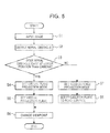
- FIG. 5 is a flowchart showing an example of the operation of the bird's-eye image generating apparatus 10 according to the first embodiment.
- the image input unit 4 inputs an image of an area behind the vehicle (in step S1), the image being captured by the camera 1 installed at the surface of the rear portion of the vehicle.
- the ultrasonic sensor 2 and the obstacle determining unit 3 detect an aerial obstacle 200 behind the vehicle (in step S2).
- the obstacle determining unit 3 determines whether or not any aerial obstacle 200 exists behind the vehicle, and when any aerial obstacle 200 exists, the obstacle determining unit 3 detects the height of the predicted contact portion 50 of the aerial obstacle 200.
- the mode control unit 6 determines whether or not the obstacle determining unit 3 has detected any aerial obstacle 200 having a predicted contact portion 50 that exists at a lower position than the camera 1 (in step S3). Upon determining that the obstacle determining unit 3 has detected any aerial obstacle 200 having a predicted contact portion 50 that exists at a lower position than the height of the camera 1, the mode control unit 6 sets the bird's-eye image generating unit 5 into the virtual-plane projection mode (in step S4).
- the viewpoint-conversion processing unit 5a of the bird's-eye image generating unit 5 sets the virtual projection plane VP to the height of the predicted contact portion 50 that is the closest to the vehicle (in step S5).
- the viewpoint-conversion processing unit 5a then performs viewpoint conversion processing so as to project the pixels of the image input in step S1 onto the virtual projection plane VP set in step S5 to thereby generate a one-direction bird's-eye image of the area behind the vehicle viewed from a virtual viewpoint thereabove toward the camera 1 (in step S6).
- the mode control unit 6 determines that the obstacle determining unit 3 has not detected any aerial obstacle 200 having a predicted contact portion 50 that exists at a lower position than the height of the camera 1 behind the vehicle, i.e., when the obstacle determining unit 3 determines that any aerial obstacle 200 does not exist behind the vehicle, or when the obstacle determining unit 3 determines that an aerial obstacle 200 exists but the height of the predicted contact portion 50 thereof is larger than the height of the camera 1, the mode control unit 6 sets the bird's-eye image generating unit 5 into the road-surface projection mode (in step S7).
- the viewpoint-conversion processing unit 5a in the bird's-eye image generating unit 5 sets the projection plane to the height of the road surface (in step S8).
- the viewpoint-conversion processing unit 5a then performs viewpoint conversion processing so as to project the pixels of the image input in step S1 onto the road surface (in step S6) to thereby generate a one-direction bird's-eye image that is an image of the area behind the vehicle viewed from a virtual viewpoint thereabove toward the camera 1.
- the virtual projection plane VP is set to the height where the predicted contact portion 50 of the detected aerial obstacle 200 exists and performs viewpoint conversion processing so as to project the pixels of the captured image onto the virtual projection plane VP, to thereby generate a one-direction bird's-eye image. Consequently, the height of the projection plane and the height of the predicted contact portion 50 of the aerial obstacle 200 match each other, so that the distance between the vehicle and the predicted contact portion 50 that exists at the height is accurately expressed on the one-direction bird's-eye image. Thus, as shown in FIG. 4 , it is possible to obtain a one-direction bird's-eye image that accurately expresses the distance between the vehicle and the predicted contact portion 50 of the aerial obstacle 200.
- FIG. 6 is a block diagram showing an example of the configuration of a bird's-eye image generating apparatus 20 according to a second embodiment of the present invention.
- units denoted by the same reference numerals as those shown in FIG. 1 have the same functions, and thus the descriptions thereof will not be given below.
- the second embodiment shown in FIG. 6 is different from the first embodiment shown in FIG. 1 in that a viewpoint-conversion processing unit 5c in the bird's-eye image generating unit 5 performs different processing from that performed by the viewpoint-conversion processing unit 5a in the first embodiment. That is, the configuration in the second embodiment shown in FIG. 6 includes, instead of the viewpoint-conversion processing unit 5a shown in FIG. 1 , the viewpoint-conversion processing unit 5c that performs different processing therefrom.
- the viewpoint-conversion processing unit 5c performs viewpoint conversion processing so as to project the pixels of the image portion within the range onto the road surface. That is, the viewpoint-conversion processing unit 5c performs viewpoint conversion processing by using the viewpoint-conversion mapping table that uses the road surface as the projection plane. With respect to an image portion beyond the range of distance from the vehicle to the predicted contact portion 50, the viewpoint-conversion processing unit 5c also performs viewpoint conversion processing so as to project the pixels of the image portion beyond the range onto the virtual projection plane VP. That is, the viewpoint-conversion processing unit 5c performs viewpoint conversion processing by using the viewpoint-conversion mapping table associated with the virtual projection plane VP corresponding to the height of the predicted contact portion 50.
- FIG. 7 is a schematic view showing a projection plane according to the second embodiment.
- the viewpoint-conversion processing unit 5c sets a projection plane RP to the road surface with respect to an image portion of an area that exists at a nearer position than the predicted contact portion 50 of the aerial obstacle 200, viewed from the vehicle 100, and also sets a virtual projection plane VP with respect to an image portion of an area that exists at a farther position than the predicted contact portion 50 of the aerial obstacle 200, viewed from the vehicle 100, to perform viewpoint conversion processing.
- the resulting one-direction bird's-eye image is generally compressed toward the camera 1 (toward the vehicle) by an amount corresponding to the higher position of the set projection plane than the road surface, compared to the case in which the projection plane is set to the road surface.
- an image portion located within the range from the vehicle to the predicted contact portion 50 of the aerial obstacle 200 is also compressed toward the vehicle.
- viewpoint conversion processing is performed so as to project the pixels of the image onto the projection plane that is set to the height of the road surface.
- the image of the nearer area is not compressed toward the vehicle.
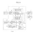
- FIG. 8 is a block diagram showing an example of the configuration of a bird's-eye image generating apparatus 30 according to a third embodiment of the present invention.
- units denoted by the same reference numerals as those shown in FIG. 1 have the same functions, and thus the descriptions thereof will not be given below.
- the third embodiment shown in FIG. 8 is different from the first embodiment shown in FIG. 1 in that a mode control unit 16 performs different processing from that performed by the mode control unit 6 in the first embodiment. That is, the configuration in the third embodiment shown in FIG. 8 includes, instead of the mode control unit 6 shown in FIG. 1 , the mode control unit 16 that performs different processing therefrom.
- the third embodiment has a configuration in which a vehicle movement-amount detecting unit 17 and a table storage unit 18 are added to the configuration shown in FIG. 1 .
- the timing of switching the operation mode from the road-surface projection mode to the virtual-plane projection mode is varied from that in the first embodiment.
- a vehicle 100 in which the surface of the rear portion thereof has a shape that protrudes rearward by an amount corresponding to the size of its trunk, as shown in FIG. 9 will be discussed below by way of example.
- a depression portion defined by space (where the vehicle body does not exist) exists above and below the trunk.
- the movement-allowed distance is substantially the same as the horizontal dimension of the space in the depression portion.
- the horizontal dimension of the space i.e., the distance between the surface of the most outwardly protruding portion and the surface of the most inwardly depressing portion
- the horizontal dimension of the space differs depending on the height from the road surface, though depending also on the shape of the vehicle (see the horizontal arrows pointing forward and rearward, in FIG. 9 ).
- the table storage unit 18 stores a distance table in which the heights of predicted contact portions 50 from the road surface and the movement-allowed distances of the vehicle 100 are associated with each other. That is, the table storage unit 18 stores, as the movement-allowed distances, the horizontal dimensions of space which are associated with the heights from the road surface.
- FIG. 10 shows one example of the distance table. Information in the first row in the distance table shown in FIG. 10 indicates that the movement-allowed distance allowed until the vehicle 100 makes contact with the predicted contact portion 50 when the predicted contact portion 50 exists at a height of 10 cm from the road surface is 50 cm larger than the movement-allowed distance allowed until the vehicle 100 makes contact with the predicted contact portion 50 when the predicted contact portion 50 exists at the height of the trunk that defines the protrusion portion.
- information in the second row in the distance table indicates that the movement-allowed distance allowed until the vehicle 100 makes contact with the predicted contact portion 50 when the predicted contact portion 50 exists at a height of 20 cm from the road surface is 30 cm larger than the movement-allowed distance allowed until the vehicle 100 makes contact with the predicted contact portion 50 when the predicted contact portion 50 exists at the height of the trunk that defines the protrusion portion.
- Information in the third to fifth rows in the distance table indicates that all movement-allowed distances for heights of 30 to 50 cm from the road surface are 0 cm, since the trunk that defines the protrusion portion exists at positions at heights of 30 to 50 cm.
- the camera 1 is installed at the surface of the rear portion of the trunk at a height of 50 cm from the road surface and, when the predicted contact portion 50 exists at a higher position than the position of the camera 1, the operation mode is not switched to the virtual-plane projection mode. Since the operation mode is not switched to the virtual-plane projection mode when the height from the road surface is 50 cm or more, no movement-allowed distance for a height of 50 cm or more is required and the movement-allowed distances associated with heights of up to 50 cm are stored in the form of the distance table.
- the vehicle movement-amount detecting unit 17 shown in FIG. 8 detects the amount of movement of the vehicle.
- the vehicle equipped with the bird's-eye image generating apparatus 30 is provided with a dead reckoning sensor (not shown).
- the dead reckoning sensor has a distance sensor for outputting a single pulse for each predetermined travel distance of the vehicle.
- the vehicle movement-amount detecting unit 17 sequentially receives the pulses output from the distance sensor, and detects the amount of movement of the vehicle based on the number of received pulses.
- the mode control unit 16 refers to the distance table, stored in the table storage unit 18, to obtain the vehicle movement-allowed distance corresponding to the height of the predicted contact portion 50 detected by the obstacle determining unit 3. Then, when the height of the predicted contact portion 50 and the height stored in the distance table do not match each other completely, the mode control unit 16 obtains the movement-allowed distance corresponding to a height that is the closest to the height of the predicted contact portion 50.
- the mode control unit 16 monitors whether or not the vehicle has moved by an amount corresponding to the movement-allowed distance, obtained from the distance table, from when the aerial obstacle 200 is detected. Upon detecting that the vehicle has moved by an amount corresponding to the movement-allowed distance, the mode control unit 16 switches the operation mode from the road-surface projection mode to the virtual-plane projection mode.
- FIG. 11 is a flowchart showing an example of the operation of the bird's-eye image generating apparatus 30 according to the third embodiment.
- the image input unit 4 inputs an image of an area behind the vehicle (in step S11), the image being captured by the camera 1 installed at the surface of the rear portion of the vehicle.
- the ultrasonic sensor 2 and the obstacle determining unit 3 detect an aerial obstacle 200 behind the vehicle (in step S12).
- the obstacle determining unit 3 determines whether or not an aerial obstacle 200 exists behind the vehicle, and when an aerial obstacle 200 exists, the obstacle determining unit 3 detects the height of the predicted contact portion 50 of the aerial obstacle 200.
- the mode control unit 16 determines whether or not the obstacle determining unit 3 has detected an aerial obstacle 200 having a predicted contact portion 50 that exists at a lower position than the height of the camera 1 (in step S13). Upon determining that the obstacle determining unit 3 has detected an aerial obstacle 200 having a predicted contact portion 50 that exists at a lower position than the height of the camera 1, the mode control unit 16 refers to the distance table, stored in the table storage unit 18, to obtain the movement-allowed distance corresponding to the height of the predicted contact portion 50. Then, based on the amount of vehicle movement detected by the vehicle movement-amount detecting unit 17, the mode control unit 16 determines whether or not the vehicle has moved by an amount corresponding to the movement-allowed distance from when the aerial obstacle 200 is detected (in step S14).
- the mode control unit 16 repeats the determination processing in step S14, until it determines that the vehicle has moved by an amount corresponding to the movement-allowed distance. Upon determining that the vehicle has moved by an amount corresponding to the movement-allowed distance, the mode control unit 16 sets the bird's-eye image generating unit 5 into the virtual-plane projection mode (in step S15).
- the viewpoint-conversion processing unit 5a of the bird's-eye image generating unit 5 sets the virtual projection plane VP to the height of the predicted contact portion 50 that is the closest to the vehicle (in step S16).
- the viewpoint-conversion processing unit 5a then performs viewpoint conversion processing so as to project the pixels of the image input in step S11 onto the virtual projection plane VP set in step S16 to thereby generate a one-direction bird's-eye image that is an image of the area behind the vehicle viewed from a virtual viewpoint thereabove toward the camera 1 (in step S17).
- the mode control unit 16 determines that the obstacle determining unit 3 has not detected any aerial obstacle 200 having a predicted contact portion 50 that exists at a lower position than the height of the camera 1 behind the vehicle, i.e., when the obstacle determining unit 3 determines that any aerial obstacle 200 does not exist behind the vehicle, or when the obstacle determining unit 3 determines that an aerial obstacle 200 exists but the height of the predicted contact portion 50 thereof is larger than the height of the camera 1, the mode control unit 16 sets the bird's-eye image generating unit 5 into the road-surface projection mode (in step S18).
- the viewpoint-conversion processing unit 5a in the bird's-eye image generating unit 5 sets the projection plane to the height of the road surface (in step S19).
- the viewpoint-conversion processing unit 5a then performs viewpoint conversion processing so as to project the pixels of the image input in step S11 onto the road surface (in step S17) to thereby generate a one-direction bird's-eye image that is an image of the area behind the vehicle viewed from a virtual viewpoint thereabove toward the camera 1.
- the model control unit 16 switches the operation mode from the road-surface projection mode to the virtual-plane projection mode.
- the timing of switching the operation mode from the road-surface projection mode to the virtual-plane projection mode can be delayed to the time at which the vehicle has moved by an amount corresponding to the movement-allowed distance after the aerial obstacle 200 is detected, not to the time immediately after the aerial obstacle 200 is detected. Since the movement-allowed distances are set considering the space distance between the protrusion portion and the depression portion of the vehicle, a margin of distance is allowed until the vehicle actually makes contact with the predicted contact portion 50 of the aerial obstacle 200 even if the timing of switching the operation mode to the virtual-plane projection mode is delayed. With this arrangement, the timing at which the image is compressed by the viewpoint conversion processing that uses the set virtual projection plane VP can be delayed as long as possible.
- the viewpoint-conversion processing unit 5c shown in FIG. 6 instead of the viewpoint-conversion processing unit 5a, may be used in the configuration shown in FIG. 8 .
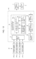
- FIG. 12 is a diagram showing an example of the configuration of a bird's-eye image generating apparatus 40, which is one example of such a case.
- units denoted by the same reference numerals as those shown in FIG. 1 have the same functions, and thus the descriptions thereof will not be given below.
- multiple cameras 21, which include a front camera 21a, a left-side camera 21b, a right-side camera 21c, and a rear camera 21d, are installed at respective different positions of a vehicle to photograph surroundings of the vehicle.
- the front camera 21a is disposed at the surface of a front portion of the vehicle to capture an image of an area in front of the vehicle.
- the left-side camera 21b is disposed on a left-side surface of the vehicle to capture an image of an area on the left side of the vehicle.
- the right-side camera 21c is disposed on a right-side surface of the vehicle to capture an image of an area on the right side of the vehicle.
- the rear camera 21d is disposed on the surface of a rear portion of the vehicle to capture an image of an area behind the vehicle.
- Ultrasonic sensors 22, each having directionality in a predetermined range, are provided at, for example, front, rear, left, and right portions of the vehicle.
- an obstacle determining unit 23 determines whether or not the detected obstacle is an aerial object 200.
- the obstacle determining unit 23 also detects the distance from the vehicle to the aerial obstacle 200 and the height of the predicted contact portion 50 thereof.
- the obstacle determining unit 23 further determines whether the detected height of the predicted contact portion 50 is larger than or smaller than the height of the installation position of the camera 21.
- a viewpoint-conversion processing unit 25 converts the viewpoints of the vehicle-surroundings images captured by the cameras 21a to 21d, and combines the viewpoint-converted images to thereby generate a vehicle-surroundings bird's-eye image viewed from a virtual viewpoint above the vehicle.
- the viewpoint-conversion processing unit 25 includes a viewpoint-conversion processing unit 25a, a mapping-table-information storage unit 25b, and an image storage unit 25c.
- the viewpoint-conversion processing unit 25a receives the images, captured by the cameras 21a to 21d, from the image input unit 4. In accordance with mapping-table information (coordinate conversion information) stored in the mapping-table-information storage unit 25b, the viewpoint conversion processing unit 25a generates a background image of the vehicle surroundings viewed from thereabove.
- the background image is generated based on the vehicle-surroundings images captured by the cameras 21a to 21d installed on the vehicle.
- the background image contains only the actual background and an obstacle or obstacles therein and does not contain an image of the vehicle.
- the viewpoint-conversion processing unit 25a reads, from the image storage unit 25c, vehicle-image data representing an image of the vehicle viewed from thereabove, and superimposes the read image on a predetermined position in the background image (e.g., on a center position where a vehicle is located in the background image). This processing generates a vehicle-surroundings bird's-eye image in which the background image and the vehicle image are combined.
- the mapping-table information stored in the mapping-table-information storage unit 25b contains information specifying relationships between the positions of the pixels of images captured by the cameras 21a to 21d and the positions of the pixels of the background image that is an image of the surroundings of the vehicle viewed from thereabove, i.e., coordinate conversion information indicating to which pixel of the back ground image one pixel of the captured images corresponds.
- the image storage unit 25c stores vehicle image data representing an image of the vehicle viewed from thereabove.
- the viewpoint-conversion processing unit 25a reads the vehicle image data from the image storage unit 25c, as needed.
- the mapping-table-information storage unit 25b stores a viewpoint-conversion mapping table corresponding to the height of the road surface and multiple viewpoint-conversion mapping tables associated with virtual projection planes VP having different heights from the road surface. While the operation mode is set in the road-surface projection mode, the viewpoint-conversion processing unit 25a performs viewpoint conversion processing by using the viewpoint-conversion mapping table corresponding to the height of the road surface. On the other hand, when the operation mode is set in the virtual-plane projection mode, the viewpoint-conversion processing unit 25a performs viewpoint conversion processing by using the viewpoint-conversion mapping table associated with the viewpoint projection plane VP corresponding to the height of the predicted contact portion 50 of the aerial obstacle 200 detected by the obstacle determining unit 23.
- the mode control unit 26 performs control so as to switch the operation mode from the road-surface projection mode to the virtual-plane projection mode.
- the mode control unit 26 switches the operation mode from the road-surface projection mode to the virtual-plane projection mode, with respect to an image captured by the front camera 21a.
- the mode control unit 26 maintains the road-surface projection mode with respect to images captured by the three cameras, i.e., the left-side camera 21b, the right-side camera 21c, and the rear camera 21d.
- the arrangement may be such that, when an aerial obstacle 200 is detected in at least one direction of the front, rear, left, and right directions, the operation mode is switched from the road-surface projection mode to the virtual-plane projection mode with respect to images captured in all directions.
- the actual movement-allowed distance is less than 50 cm.
- the distance between the predicted contact portion 50 and the wall can be detected by the ultrasonic sensor 2.
- the distance may be used as a movement-allowed distance instead of the obtained movement-allowed distance.
Landscapes
- Engineering & Computer Science (AREA)
- Multimedia (AREA)
- Radar, Positioning & Navigation (AREA)
- Remote Sensing (AREA)
- Transportation (AREA)
- Human Computer Interaction (AREA)
- Mechanical Engineering (AREA)
- Computer Vision & Pattern Recognition (AREA)
- Physics & Mathematics (AREA)
- General Physics & Mathematics (AREA)
- Theoretical Computer Science (AREA)
- Closed-Circuit Television Systems (AREA)
- Image Processing (AREA)
- Image Analysis (AREA)
Abstract
Description
- The present invention relates to methods and apparatuses for generating bird's-eye images. More specifically, the present invention relates to a method and an apparatus for generating a bird's-eye image, viewed from a virtual viewpoint above a vehicle, by performing viewpoint conversion processing on an image of vehicle surroundings photographed by a camera.
- To date, a technology has been proposed that captures images of surroundings of a vehicle by using multiple cameras installed at front, rear, left, and right portions of the vehicle, performs viewpoint conversion processing on the captured images to generate a bird's eye image viewed from a virtual viewpoint above the vehicle (this bird's eye image will hereinafter be referred to as a "vehicle-surroundings bird's-eye image") and displays the generated vehicle-surroundings bird's-eye image on a display device, for example, as disclosed in Japanese Patent No.
3300334 - In addition, a technology has also been proposed that performs viewpoint conversion processing on an image of vehicle surroundings photographed by one camera installed at a predetermination position of a vehicle to generate a bird's eye image viewed from a virtual viewpoint thereabove (this bird's eye image will hereinafter be referred to as a "one-direction bird's-eye image") and displays the one-direction bird's eye image on a display device.
- According to the vehicle-surroundings bird's-eye image display technology and the one-direction bird's-eye image display technology (which are collectively referred to as "bird's eye image display technology" hereinafter), a driver can drive a vehicle so as to prevent collision and so on of the vehicle with obstacles in its surroundings by recognizing the positional relationships between the vehicle and the obstacles through checking the vehicle-surroundings bird's-eye image or the one-direction bird's-eye image displayed on the display device in the vehicle.
- In the bird's-eye image display technology, in the viewpoint conversion processing performed on the image or images captured by the camera, a projection plane is set at the height of a road surface in the vehicle surroundings and pixels of the captured image(s) are projected onto the projection plane. Since the height of the road surface is used as a reference for the viewpoint conversion processing, a three-dimensional obstacle is displayed with a shape that falls toward a farther side (viewed from the camera (the vehicle)) relative to a portion at which obstacle makes contact with the ground. Even in this case, since the absolute distance on the road surface between the vehicle and the obstacle is accurately expressed, the driver can almost correctly have a sense of distance between the vehicle and the obstacle in its surroundings.
- However, when the obstacle in the vehicle surroundings is a three-dimensional object having a portion (hereinafter referred to as a "predicted contact portion") that lies at a certain height above the road surface and that may make contact with the vehicle when the vehicle moves, projection of an image of the predicted contact portion results in display in which the predicted contact portion is displayed at a farther distance than the actual distance thereof from the vehicle. Thus, there are problems in that, when the vehicle moves toward the obstacle, the driver may have a sense of discomfort due to, for example, sudden approach of an obstacle, or the driver cannot perform a stopping operation in time to result in collision of the vehicle.
- One example of the obstacle that may cause such problems is a clothes-drying pole. That is, when stands at two opposite ends are not located in a vehicle moving direction and the pole placed across the stands is located in the vehicle moving direction, the pole acts as the obstacle that causes the above-described problems. Other examples of the obstacle that causes the above-described problems include a three-dimensional object that has a shape that extends substantially upward from the road surface and bends or curves halfway toward the vehicle and an object having a shape that protrudes toward the vehicle from one portion at a certain height of a wall located in the vehicle moving direction. The obstacle that causes the above-described problems will hereinafter be referred to as an "aerial obstacle".
-
FIGS. 13A and 13B are schematic views illustrating the above-described problems of the related art.FIGS. 13A and 13B show the principle of how the predicted contact portion of an aerial obstacle is displayed at a position farther than the actual distance from the vehicle.FIG. 13A shows the positional relationship between avehicle 100 and anaerial obstacle 200 and a state in which theaerial obstacle 200 is projected on a road surface.FIG. 13B shows a one-direction bird's-eye image generated by viewpoint conversion processing through projection of an image onto the road surface. - A description in this case is given of one example of a case in which a pole (e.g., a clothes-drying pole) that is placed across two
stands vehicle 100 as anaerial obstacle 200. As shown inFIG. 13A , the actual distance from thevehicle 100 to theaerial obstacle 200 is assumed to be D1. In this case, when the position of acamera 300 is used as a reference to project an image of theaerial obstacle 200 onto a projection plane set at the height of the road surface, the viewpoint of the image of theaerial obstacle 200 is converted into the viewpoint for a position at a distance of D2 (>D1) from thevehicle 100. - As a result, as shown in
FIG. 13B , the image of theaerial obstacle 200 is displayed at a position farther than the actual distance D1 from thevehicle 100. A dotted line shown inFIG. 13B indicates a guide line that is superimposed on the one-direction bird's-eye image and is displayed at a predetermined distance (e.g., 50 cm) from thevehicle 100. In the example shown inFIGS. 13A and 13B , theaerial obstacle 200 exists at the same distance (D1 = 50 cm) as the position where the guide line is displayed. Thus, even though the guide line is displayed for convenience of the driver, there are problems in that the driver is easily confused since the position where theaerial obstacle 200 is displayed is erroneous. - The present invention has been made in order to overcome such problems, and an object of the present invention it to generate and display a bird's eye image that accurately expresses the distance between a vehicle and an aerial obstacle when the aerial obstacle exists in vehicle surroundings.
- In order to overcome the above-described problems, according to one aspect of the present invention, when a an obstacle that exists in an image-capture-device installation direction in a vehicle surroundings and that has a predicted contact portion at a certain height above a road surface, the predicted contact portion being a portion with which the vehicle may make contact when the vehicle moves, is detected, a virtual projection plane is set to a position at a height where the predicted contact portion exists and viewpoint conversion processing is performed so as to project pixels of a captured image onto the virtual projection plane, to thereby generate a bird's-eye image.
- According to another aspect of the present invention, with respect to an image within a range of distance from the vehicle to the predicted contact portion, the viewpoint conversion processing is performed so as to project the pixels onto a projection plane set at a height of the road surface, and with respect to an image father than the predicted contact portion, the viewpoint conversion processing is performed so as to project the pixels on to the virtual projection plane.
- According to still another aspect of the present invention, when the obstacle is detected and it is then detected that the vehicle has moved by an amount corresponding to a movement-allowed distance pre-stored in association with the height of the predicted contact portion of the detected obstacle, an operation mode is switched from a road-surface projection mode to a virtual-plane projection mode. In the road-surface projection mode, the viewpoint conversion processing is performed so as to project the pixels of the captured image onto a projection plane set at the height of the road surface, and in the virtual-plane projection mode, the viewpoint conversion processing is performed so as to project the pixels of the captured image onto the virtual projection plane.
- When a vehicle surface at which the image capture device is installed has a protrusion/depression shape in the direction in which the obstacle exists, the depression portion has space where the vehicle body does not exist, compared to the protrusion portion. The dimension in the horizontal direction (in the moving direction of the vehicle) differs depending on the height from the road surface. The above-mentioned movement-allowed distance has a value corresponding to the horizontal dimension of the space that differs depending on the height from the road surface.
- According to the present invention configured as described above, when a predicted contact portion that may contact with the vehicle exists at a certain height above the road surface, viewpoint conversion processing is performed so as to project the pixels of a captured image on a projection surface at the height of the predicted contact portion. Consequently, the height of the projection surface and the height of the predicted contact portion of the obstacle match each other, and the distance between predicted contact portion at the height and the vehicle is accurately expressed on a bird's eye image resulting from the viewpoint conversion. Thus, it is possible to obtain a bird's-eye image that accurately expresses the distance between the vehicle and the predicted contact portion of the obstacle.
- As described above, when the virtual projection surface is set at the height of the predicted contact portion of the obstacle to perform viewpoint conversion processing, the bird's eye image is generally compressed toward the image capture device (i.e., toward the vehicle) by an amount corresponding to the larger height of the projection surface than the road surface. Although the compression effect can prevent the predicted contact portion from being expressed at a farther distance than the actual distance of the vehicle, an image in the range from the vehicle to the predicted contact portion of the obstacle is also compressed toward the vehicle.
- In contrast, according to the present invention, since viewpoint conversion processing is performed so as to project the pixels onto the projection surface set at the height of the road surface with respect to an image in the range from the vehicle to the predicted contact portion of the obstacle, the image in the range is not compressed toward the vehicle. With this arrangement, when a white line (which is not a three-dimensional obstacle) is drawn on a road surface within the range from the vehicle to the predicted contact portion, a bird's-eye image in which the white line appears closer to the vehicle is not obtained, and instead, the actual distance between the vehicle and the white line is accurately expressed on the bird's-eye image resulting from the virtual conversion. Thus, it is possible to obtain a bird's eye image that accurately expresses the distance between the vehicle and the white line that lies between the vehicle and the obstacle as well as the distance between the vehicle and the predicted contact portion of the obstacle.
- When the vehicle surface at which the image capture device is installed has a protrusion/depression shape in the direction in which the obstacle exists, the time at which the vehicle makes contact with the obstacle when the vehicle moves toward the obstacle varies depending on the height of the predicted contact portion of the obstacle. That is, when the height of the protrusion portion of the vehicle and the height of the predicted contact portion of the obstacle do not mach each other, the time at which the vehicle makes contact with the obstacle is delayed compared to a case in which the heights match each other.
- According to yet another aspect of the present invention, the timing of switching the operation mode from the road-surface projection mode to the virtual-plane projection mode can be delayed to the time at which the vehicle has moved by an amount corresponding to a movement-allowed distance after the obstacle is detected, not to the time immediately after the obstacle is detected. Since the movement-allowed distance is set considering the space distances between the protrusion portion and the depression portion of the vehicle, a margin of distance is allowed until the vehicle actually makes contact with the obstacle even if the timing of switching the operation mode to the virtual-plane projection mode is delayed. With this arrangement, the timing at which the image is compressed by the viewpoint conversion processing that uses the set virtual projection plane can be delayed as long as possible.
-
-
FIG. 1 is a block diagram showing an example of the configuration of a bird's-eye image generating apparatus according to a first embodiment of the present invention; -
FIGS. 2A and 2B are schematic views each showing one example of an aerial obstacle having a predicted contact portion that exists at a certain height above a road surface; -
FIGS. 3A and 3B show a virtual projection plane set by a viewpoint-conversion processing unit in the first embodiment; -
FIG. 4 shows one example of a one-direction bird's-eye image generated by a bird's-eye image generating unit in the first embodiment; -
FIG. 5 is a flowchart showing an example of the operation of the bird's-eye image generating apparatus according to the first embodiment; -
FIG. 6 is a block diagram showing an example of the configuration of a bird's-eye image generating apparatus according to a second embodiment of the present invention; -
FIG. 7 is a schematic view showing a projection plane set by a viewpoint-conversion processing unit in the second embodiment; -
FIG. 8 is a block diagram showing an example of the configuration of a bird's-eye image generating apparatus according to a third embodiment of the present invention; -
FIG. 9 is a schematic view illustrating a movement-allowed distance in the third embodiment; -
FIG. 10 shows one example of a distance table stored in a table storage unit in the third embodiment; -
FIG. 11 is a flowchart showing an example of the operation of the bird's-eye image generating apparatus according to the third embodiment; -
FIG. 12 is a block diagram showing an example of the configuration of a bird's-eye image generating apparatus according to the present invention which is applied to a case in which a vehicle-surroundings bird's-eye image is generated; and -
FIGS. 13A and 13B illustrate problems of the related art. - One embodiment of the present invention will be described below with reference to the accompanying drawings.
FIG. 1 is a block diagram showing an example of the configuration of a bird's-eyeimage generating apparatus 10 according to a first embodiment of the present invention. Referring toFIG. 1 , acamera 1 is installed on a vehicle to photograph surroundings thereof. Thecamera 1 is disposed at a predetermined height, for example, on the surface of a rear portion of the vehicle to capture an image behind the vehicle. Thecamera 1 has, for example, a super-wide-angle lens such as a fisheye lens, and is capable of photographing a wide range behind the vehicle. - An
ultrasonic sensor 2 detects the presence/absence of an obstacle in surroundings of the vehicle and also detects the distance from the vehicle to the obstacle, based on a reflection wave of a transmitted ultrasonic wave. Theultrasonic sensor 2 has a sensor head that transmits the ultrasonic wave and receives an ultrasonic wave reflected by an obstacle. By measuring time from the transmission of the ultrasonic wave to the reception thereof, theultrasonic sensor 2 detects the position of the object. While theultrasonic sensor 2 is used in this case, another sensor such as a millimeter-wave sensor may be used. - When the
ultrasonic sensor 2 detects an obstacle, anobstacle determining unit 3 determines whether or not the detected obstacle is an aerial object. The term "aerial object" as used herein refers to a three-dimensional object that exists in a camera-installation direction in the vehicle surroundings and that has a predicted contact portion at a certain height above a road surface, the predicted contact portion being a portion with which the vehicle may make contact when the vehicle moves backward. Theultrasonic sensor 2 and theobstacle determining unit 3 constitute an obstacle detecting unit in the present invention. -
FIGS. 2A and 2B are schematic views each showing one example of anaerial obstacle 200 having a predictedcontact portion 50 that exists at a certain height above a road surface. As shown inFIG. 2A , one possible example of theaerial object 200 is a three-dimensional object having a shape that extends substantially upward from the road surface and bends or curves halfway toward avehicle 100. As shown inFIG. 2B , another example of theaerial obstacle 200 is a three-dimensional object having a shape that protrudes toward thevehicle 100 from one portion at a certain height of a wall located in the vehicle moving direction (i.e., located behind the vehicle). Other examples of theaerial obstacle 200 include a clothes-drying pole and so on. - The
ultrasonic sensor 2 transmits ultrasonic waves to various heights and detects the position of an object by measuring time from the transmission of the ultrasonic waves to the reception thereof. When the object is anaerial obstacle 200, the amount of measurement time of ultrasonic waves reflected by the predictedcontact portion 50 is smaller than the amount of measurement time of ultrasonic waves reflected by other portions. Thus, when theultrasonic sensor 2 detects a three-dimensional object having a portion (a predicted contact portion 50) that exists at a certain height above the road surface and that is the shortest in the measurement time, theobstacle determining unit 3 determines that the three-dimensional object is anaerial obstacle 200. At the same time, theobstacle determining unit 3 detects the height of the predictedcontact portion 50 from the road surface. - The
obstacle determining unit 3 further determines whether the detected height of the predictedcontact portion 50 is larger than or smaller than the height of the installation position of thecamera 1. For example, theobstacle determining unit 3 stores the height of thecamera 1 as known information, and compares the known height of thecamera 1 with the height of the predictedcontact portion 50 detected by theobject determining unit 3 to thereby determine whether the height of the predictedcontact portion 50 is larger than or smaller than the height of thecamera 1. - An
image input unit 4 inputs an image of vehicle surroundings, photographed by thecamera 1, to the bird's-eyeimage generating apparatus 10. A bird's-eyeimage generating unit 5 converts the viewpoint of the image captured by thecamera 1 and input by theimage input unit 4 to generate a one-direction bird's-eye image viewed from a virtual viewpoint above the vehicle. The bird's-eyeimage generating unit 5 includes a viewpoint-conversion processing unit 5a and a mapping-table-information storage unit 5b. The viewpoint-conversion processing unit 5a receives the image, captured by thecamera 1, from theimage input unit 4. In accordance with mapping-table information (coordinate conversion information) stored in the mapping-table-information storage unit 5b, the viewpoint-conversion processing unit 5a generates a one-direction bird's-eye image that is an image of vehicle surroundings viewed from thereabove. - The mapping-table information stored in the mapping-table-
information storage unit 5b contains information specifying relationships between the positions of pixels of an image captured by thecamera 1 and the positions of pixels of a one-direction bird's-eye image that is an image of vehicle surroundings viewed from thereabove, i.e., coordinate conversion information indicating to which pixel of the one-direction bird's eye image one pixel of the captured image corresponds. - A
mode control unit 6 controls an operation mode of the bird's-eyeimage generating unit 5, in accordance with the result of theaerial obstacle 200 detection performed by theobstacle determining unit 3. The bird's-eyeimage generating unit 5 has a road-surface projection mode and a virtual-plane projection mode. In the road-surface projection mode, the bird's-eyeimage generating unit 5 performs viewpoint conversion processing so as to project the pixels of the image input by theimage input unit 4 onto a projection plane set at the height of the road surface in the vehicle surroundings, and in the virtual-plane projection mode, the bird's-eyeimage generating unit 5 performs viewpoint conversion processing so as to project the pixels of the image input by theimage input unit 4 onto a virtual projection plane (described blow in detail). - When the
obstacle determining unit 3 detects theaerial obstacle 200 behind the vehicle and also determines that the height of the predictedcontact portion 50 of theaerial obstacle 200 is smaller than the height of thecamera 1, themode control unit 6 performs control so as to switch the operation mode from the road-surface projection mode to the virtual-plane projection mode. In other cases, i.e., when anaerial obstacle 200 does not exist or when anaerial obstacle 200 exists but the height of the predictedcontact portion 50 thereof is larger than the height of thecamera 1, themode control unit 6 sets the bird's-eyeimage generating unit 5 into the road-surface projection mode. - In the road-surface projection mode, the viewpoint-
conversion processing unit 5a in the bird's-eyeimage generating unit 5 sets the projection plane to the height of the road surface and performs viewpoint conversion processing so as to project the pixels of the image input by theimage input unit 4 onto the road surface to thereby generate a one-direction bird's-eye image that is an image of the vehicle surroundings viewed from a virtual viewpoint thereabove toward thecamera 1. More specifically, the mapping-table-information storage unit 5b stores a viewpoint-conversion mapping table corresponding to the height of the road surface. The viewpoint-conversion processing unit 5a performs viewpoint conversion processing by using the viewpoint-conversion mapping table that uses the height of the road surface as the projection plane. - On the other hand, in the virtual-plane projection mode, as shown in
FIGS. 3A and 3B , the viewpoint-conversion processing unit 5a in the bird's-eyeimage generating unit 5 sets a virtual projection plane VP to the position at a height where the predictedcontact portion 50 of theaerial obstacle 200 exists, and performs viewpoint conversion processing so as to project the pixels of the image input by theimage input unit 4 onto the virtual projection plane VP. By doing so, the viewpoint-conversion processing unit 5a generates a one-direction bird's-eye image that is an image of the surroundings of thevehicle 100 viewed from a virtual viewpoint thereabove toward thecamera 1. - Specifically, the mapping-table-
information storage unit 5b in the bird's-eyeimage generating unit 5 stores multiple viewpoint-conversion mapping tables associated with multiple virtual projection planes VP having different heights from the road surface. The viewpoint-conversion processing unit 5a performs viewpoint conversion processing by using the viewpoint-conversion mapping table associated with the viewpoint projection plane VP corresponding to the height of the predictedcontact portion 50 of theaerial obstacle 200 detected by theobstacle determining unit 3. - More specifically, the mapping-table-
information storage unit 5b stores multiple viewpoint-conversion mapping tables associated with multiple virtual projection planes VP having different heights from the road surface, for example, in increments of 10 cm, i.e., heights of 10 cm, 20 cm, 30 cm, ..., and so on from the road surface. The viewpoint-conversion processing unit 5a sets the virtual projection plane VP to the height of the predictedcontact portion 50 detected by theobstacle determining unit 3, and performs viewpoint conversion processing by using the viewpoint-conversion mapping table corresponding to a height that is the closest to the height of the virtual projection plane VP. - When the
obstacle determining unit 3 detects multipleaerial obstacles 200, the viewpoint-conversion processing unit 5a sets the virtual projection plane VP to the position at a height where the predictedcontact portion 50 that is the closest to thevehicle 100 exists, based on distances from thevehicle 100 to the predictedcontact portions 50 of theaerial obstacles 200. The viewpoint-conversion processing unit 5a then performs viewpoint conversion processing by using the viewpoint-conversion mapping table corresponding to a height that is the closest to the height of the set virtual projection plane VP. - A
display control unit 7 performs control for displaying, on adisplay unit 8, the one-direction bird's-eye image generated by the bird's-eyeimage generating unit 5.FIG. 4 shows one example of the one-direction bird's-eye image generated by the bird's-eyeimage generating unit 5. In this example, a clothes-drying pole acting as anaerial obstacle 200 exists behind and 50 cm away from thevehicle 100 and a guide line (shown by a dotted line) is displayed superimposed at aposition 50 cm from thevehicle 100 on the one-direction bird's-eye image. - In the present embodiment, since the
aerial obstacle 200 exists behind thevehicle 100, the viewpoint-conversion processing unit 5a sets the virtual projection plane VP to the height of the predictedcontact portion 50 of theaerial obstacle 200 to perform viewpoint conversion processing so as to project the pixels of the captured image onto the set virtual projection plane VP, the height of the projection plane and the height of the predictedcontact portion 50 match each other. As a result, the distance between the predictedcontact portion 50 and thevehicle 100 is accurately expressed on the one-direction bird's-eye image resulting from the viewpoint conversion. In the example shown inFIG. 4 , the display position of the guide line displayed at theposition 50 cm from thevehicle 100 and the display position of the predictedcontact portion 50 of theaerial obstacle 200 that exists behind and 50 cm away from thevehicle 100 match each other completely. - The operation of the bird's-eye
image generating apparatus 10 according to the first embodiment configured as described above will be described next.FIG. 5 is a flowchart showing an example of the operation of the bird's-eyeimage generating apparatus 10 according to the first embodiment. - Referring to
FIG. 5 , first, theimage input unit 4 inputs an image of an area behind the vehicle (in step S1), the image being captured by thecamera 1 installed at the surface of the rear portion of the vehicle. Next, theultrasonic sensor 2 and theobstacle determining unit 3 detect anaerial obstacle 200 behind the vehicle (in step S2). In this case, theobstacle determining unit 3 determines whether or not anyaerial obstacle 200 exists behind the vehicle, and when anyaerial obstacle 200 exists, theobstacle determining unit 3 detects the height of the predictedcontact portion 50 of theaerial obstacle 200. - Next, the
mode control unit 6 determines whether or not theobstacle determining unit 3 has detected anyaerial obstacle 200 having a predictedcontact portion 50 that exists at a lower position than the camera 1 (in step S3). Upon determining that theobstacle determining unit 3 has detected anyaerial obstacle 200 having a predictedcontact portion 50 that exists at a lower position than the height of thecamera 1, themode control unit 6 sets the bird's-eyeimage generating unit 5 into the virtual-plane projection mode (in step S4). - Upon setting of the virtual-plane projection mode, the viewpoint-
conversion processing unit 5a of the bird's-eyeimage generating unit 5 sets the virtual projection plane VP to the height of the predictedcontact portion 50 that is the closest to the vehicle (in step S5). The viewpoint-conversion processing unit 5a then performs viewpoint conversion processing so as to project the pixels of the image input in step S1 onto the virtual projection plane VP set in step S5 to thereby generate a one-direction bird's-eye image of the area behind the vehicle viewed from a virtual viewpoint thereabove toward the camera 1 (in step S6). - On the other hand, when the
mode control unit 6 determines that theobstacle determining unit 3 has not detected anyaerial obstacle 200 having a predictedcontact portion 50 that exists at a lower position than the height of thecamera 1 behind the vehicle, i.e., when theobstacle determining unit 3 determines that anyaerial obstacle 200 does not exist behind the vehicle, or when theobstacle determining unit 3 determines that anaerial obstacle 200 exists but the height of the predictedcontact portion 50 thereof is larger than the height of thecamera 1, themode control unit 6 sets the bird's-eyeimage generating unit 5 into the road-surface projection mode (in step S7). - Upon setting of the road-surface projection mode, the viewpoint-
conversion processing unit 5a in the bird's-eyeimage generating unit 5 sets the projection plane to the height of the road surface (in step S8). The viewpoint-conversion processing unit 5a then performs viewpoint conversion processing so as to project the pixels of the image input in step S1 onto the road surface (in step S6) to thereby generate a one-direction bird's-eye image that is an image of the area behind the vehicle viewed from a virtual viewpoint thereabove toward thecamera 1. - As described above in detail, according to the first embodiment, when an
aerial obstacle 200 in the vehicle surroundings is detected, the virtual projection plane VP is set to the height where the predictedcontact portion 50 of the detectedaerial obstacle 200 exists and performs viewpoint conversion processing so as to project the pixels of the captured image onto the virtual projection plane VP, to thereby generate a one-direction bird's-eye image. Consequently, the height of the projection plane and the height of the predictedcontact portion 50 of theaerial obstacle 200 match each other, so that the distance between the vehicle and the predictedcontact portion 50 that exists at the height is accurately expressed on the one-direction bird's-eye image. Thus, as shown inFIG. 4 , it is possible to obtain a one-direction bird's-eye image that accurately expresses the distance between the vehicle and the predictedcontact portion 50 of theaerial obstacle 200. - Next, a second embodiment of the present invention will be described with reference to the accompanying drawings.
FIG. 6 is a block diagram showing an example of the configuration of a bird's-eyeimage generating apparatus 20 according to a second embodiment of the present invention. InFIG. 6 , units denoted by the same reference numerals as those shown inFIG. 1 have the same functions, and thus the descriptions thereof will not be given below. - The second embodiment shown in
FIG. 6 is different from the first embodiment shown inFIG. 1 in that a viewpoint-conversion processing unit 5c in the bird's-eyeimage generating unit 5 performs different processing from that performed by the viewpoint-conversion processing unit 5a in the first embodiment. That is, the configuration in the second embodiment shown inFIG. 6 includes, instead of the viewpoint-conversion processing unit 5a shown inFIG. 1 , the viewpoint-conversion processing unit 5c that performs different processing therefrom. - Of the entire area of an image input by the
image input unit 4, with respect to an image portion within the range of distance from the vehicle to the predictedcontact portion 50, the viewpoint-conversion processing unit 5c performs viewpoint conversion processing so as to project the pixels of the image portion within the range onto the road surface. That is, the viewpoint-conversion processing unit 5c performs viewpoint conversion processing by using the viewpoint-conversion mapping table that uses the road surface as the projection plane. With respect to an image portion beyond the range of distance from the vehicle to the predictedcontact portion 50, the viewpoint-conversion processing unit 5c also performs viewpoint conversion processing so as to project the pixels of the image portion beyond the range onto the virtual projection plane VP. That is, the viewpoint-conversion processing unit 5c performs viewpoint conversion processing by using the viewpoint-conversion mapping table associated with the virtual projection plane VP corresponding to the height of the predictedcontact portion 50. -
FIG. 7 is a schematic view showing a projection plane according to the second embodiment. As shown inFIG. 7 , when theobstacle determining unit 3 detects anaerial obstacle 200, the viewpoint-conversion processing unit 5c sets a projection plane RP to the road surface with respect to an image portion of an area that exists at a nearer position than the predictedcontact portion 50 of theaerial obstacle 200, viewed from thevehicle 100, and also sets a virtual projection plane VP with respect to an image portion of an area that exists at a farther position than the predictedcontact portion 50 of theaerial obstacle 200, viewed from thevehicle 100, to perform viewpoint conversion processing. - When the virtual projection plane VP is set to the height of the predicted
contact portion 50 of theaerial obstacle 200 to perform viewpoint conversion processing on an entire captured image, as in the first embodiment, the resulting one-direction bird's-eye image is generally compressed toward the camera 1 (toward the vehicle) by an amount corresponding to the higher position of the set projection plane than the road surface, compared to the case in which the projection plane is set to the road surface. As a result, an image portion located within the range from the vehicle to the predictedcontact portion 50 of the aerial obstacle 200 (the image portion is an image of the nearer area than the predictedcontact portion 50 of theaerial obstacle 200, when viewed from the vehicle) is also compressed toward the vehicle. In this case, for example, when a white line (which is not a three-dimensional obstacle) is drawn in the nearer area than the predictedcontact portion 50, a bird's-eye image in which the white line appears closer to the vehicle is obtained and the distance between the vehicle and the white line shown in the bird's-eye image becomes smaller than the actual distance. - In contrast, according to the second embodiment, with respect to an image of the nearer area than the predicted
contact portion 50, viewpoint conversion processing is performed so as to project the pixels of the image onto the projection plane that is set to the height of the road surface. Thus, the image of the nearer area is not compressed toward the vehicle. With this arrangement, for example, when a white line is drawn on a road surface within the range between the vehicle and the predictedcontact portion 50, a bird's-eye image in which the white line appears closer to the vehicle is not obtained, and instead, the actual distance between the vehicle and the white line is accurately expressed on the one-direction bird's-eye image resulting from the virtual conversion. Thus, it is possible to obtain a one-direction bird's-eye image that accurately expresses the distance between the vehicle and the white line that exists between the vehicle and theaerial obstacle 200 as well as the distance between the vehicle and the predictedcontact portion 50 of theaerial obstacle 200. - Next, a third embodiment of the present invention will be described with reference to the accompanying drawings.
FIG. 8 is a block diagram showing an example of the configuration of a bird's-eyeimage generating apparatus 30 according to a third embodiment of the present invention. InFIG. 8 , units denoted by the same reference numerals as those shown inFIG. 1 have the same functions, and thus the descriptions thereof will not be given below. - The third embodiment shown in
FIG. 8 is different from the first embodiment shown inFIG. 1 in that amode control unit 16 performs different processing from that performed by themode control unit 6 in the first embodiment. That is, the configuration in the third embodiment shown inFIG. 8 includes, instead of themode control unit 6 shown inFIG. 1 , themode control unit 16 that performs different processing therefrom. The third embodiment has a configuration in which a vehicle movement-amount detecting unit 17 and atable storage unit 18 are added to the configuration shown inFIG. 1 . - More specifically, in the third embodiment, considering that the vehicle rear-portion surface on which the
camera 1 is installed has a protrusion/depression shape behind the vehicle (i.e., in the direction in which an obstacle exists), the timing of switching the operation mode from the road-surface projection mode to the virtual-plane projection mode is varied from that in the first embodiment. For ease of description, avehicle 100 in which the surface of the rear portion thereof has a shape that protrudes rearward by an amount corresponding to the size of its trunk, as shown inFIG. 9 , will be discussed below by way of example. In this case, relative to the protrusion portion of the trunk, a depression portion defined by space (where the vehicle body does not exist) exists above and below the trunk. - In the presence of such space, when the height of the protrusion portion and the height of the predicted
contact portion 50 of anaerial obstacle 200 do not mach each other, a margin of distance for thevehicle 100 to move rearward is allowed until thevehicle 100 actually makes contact with the predictedcontact portion 50. The movement-allowed distance is substantially the same as the horizontal dimension of the space in the depression portion. The horizontal dimension of the space (i.e., the distance between the surface of the most outwardly protruding portion and the surface of the most inwardly depressing portion) differs depending on the height from the road surface, though depending also on the shape of the vehicle (see the horizontal arrows pointing forward and rearward, inFIG. 9 ). - Accordingly, the
table storage unit 18 stores a distance table in which the heights of predictedcontact portions 50 from the road surface and the movement-allowed distances of thevehicle 100 are associated with each other. That is, thetable storage unit 18 stores, as the movement-allowed distances, the horizontal dimensions of space which are associated with the heights from the road surface.FIG. 10 shows one example of the distance table. Information in the first row in the distance table shown inFIG. 10 indicates that the movement-allowed distance allowed until thevehicle 100 makes contact with the predictedcontact portion 50 when the predictedcontact portion 50 exists at a height of 10 cm from the road surface is 50 cm larger than the movement-allowed distance allowed until thevehicle 100 makes contact with the predictedcontact portion 50 when the predictedcontact portion 50 exists at the height of the trunk that defines the protrusion portion. - Similarly, information in the second row in the distance table indicates that the movement-allowed distance allowed until the
vehicle 100 makes contact with the predictedcontact portion 50 when the predictedcontact portion 50 exists at a height of 20 cm from the road surface is 30 cm larger than the movement-allowed distance allowed until thevehicle 100 makes contact with the predictedcontact portion 50 when the predictedcontact portion 50 exists at the height of the trunk that defines the protrusion portion. Information in the third to fifth rows in the distance table indicates that all movement-allowed distances for heights of 30 to 50 cm from the road surface are 0 cm, since the trunk that defines the protrusion portion exists at positions at heights of 30 to 50 cm. - In the example of the distance table shown in
FIG. 10 , it is assumed that thecamera 1 is installed at the surface of the rear portion of the trunk at a height of 50 cm from the road surface and, when the predictedcontact portion 50 exists at a higher position than the position of thecamera 1, the operation mode is not switched to the virtual-plane projection mode. Since the operation mode is not switched to the virtual-plane projection mode when the height from the road surface is 50 cm or more, no movement-allowed distance for a height of 50 cm or more is required and the movement-allowed distances associated with heights of up to 50 cm are stored in the form of the distance table. - The vehicle movement-
amount detecting unit 17 shown inFIG. 8 detects the amount of movement of the vehicle. For example, the vehicle equipped with the bird's-eyeimage generating apparatus 30 is provided with a dead reckoning sensor (not shown). The dead reckoning sensor has a distance sensor for outputting a single pulse for each predetermined travel distance of the vehicle. The vehicle movement-amount detecting unit 17 sequentially receives the pulses output from the distance sensor, and detects the amount of movement of the vehicle based on the number of received pulses. - When the
obstacle determining unit 3 detects anaerial obstacle 200 having a predictedcontact portion 50 that exists at a lower position than thecamera 1, themode control unit 16 refers to the distance table, stored in thetable storage unit 18, to obtain the vehicle movement-allowed distance corresponding to the height of the predictedcontact portion 50 detected by theobstacle determining unit 3. Then, when the height of the predictedcontact portion 50 and the height stored in the distance table do not match each other completely, themode control unit 16 obtains the movement-allowed distance corresponding to a height that is the closest to the height of the predictedcontact portion 50. - In addition, based on the amount of vehicle movement detected by the vehicle movement-
amount detecting unit 17, themode control unit 16 monitors whether or not the vehicle has moved by an amount corresponding to the movement-allowed distance, obtained from the distance table, from when theaerial obstacle 200 is detected. Upon detecting that the vehicle has moved by an amount corresponding to the movement-allowed distance, themode control unit 16 switches the operation mode from the road-surface projection mode to the virtual-plane projection mode. - The operation of the bird's-eye
image generating apparatus 30 according to the third embodiment configured as described above will be described next.FIG. 11 is a flowchart showing an example of the operation of the bird's-eyeimage generating apparatus 30 according to the third embodiment. - Referring to
FIG. 11 , first, theimage input unit 4 inputs an image of an area behind the vehicle (in step S11), the image being captured by thecamera 1 installed at the surface of the rear portion of the vehicle. Next, theultrasonic sensor 2 and theobstacle determining unit 3 detect anaerial obstacle 200 behind the vehicle (in step S12). In this case, theobstacle determining unit 3 determines whether or not anaerial obstacle 200 exists behind the vehicle, and when anaerial obstacle 200 exists, theobstacle determining unit 3 detects the height of the predictedcontact portion 50 of theaerial obstacle 200. - Next, the
mode control unit 16 determines whether or not theobstacle determining unit 3 has detected anaerial obstacle 200 having a predictedcontact portion 50 that exists at a lower position than the height of the camera 1 (in step S13). Upon determining that theobstacle determining unit 3 has detected anaerial obstacle 200 having a predictedcontact portion 50 that exists at a lower position than the height of thecamera 1, themode control unit 16 refers to the distance table, stored in thetable storage unit 18, to obtain the movement-allowed distance corresponding to the height of the predictedcontact portion 50. Then, based on the amount of vehicle movement detected by the vehicle movement-amount detecting unit 17, themode control unit 16 determines whether or not the vehicle has moved by an amount corresponding to the movement-allowed distance from when theaerial obstacle 200 is detected (in step S14). - In this case, the
mode control unit 16 repeats the determination processing in step S14, until it determines that the vehicle has moved by an amount corresponding to the movement-allowed distance. Upon determining that the vehicle has moved by an amount corresponding to the movement-allowed distance, themode control unit 16 sets the bird's-eyeimage generating unit 5 into the virtual-plane projection mode (in step S15). - Upon setting of the virtual-plane projection mode, the viewpoint-
conversion processing unit 5a of the bird's-eyeimage generating unit 5 sets the virtual projection plane VP to the height of the predictedcontact portion 50 that is the closest to the vehicle (in step S16). The viewpoint-conversion processing unit 5a then performs viewpoint conversion processing so as to project the pixels of the image input in step S11 onto the virtual projection plane VP set in step S16 to thereby generate a one-direction bird's-eye image that is an image of the area behind the vehicle viewed from a virtual viewpoint thereabove toward the camera 1 (in step S17). - On the other hand, when the
mode control unit 16 determines that theobstacle determining unit 3 has not detected anyaerial obstacle 200 having a predictedcontact portion 50 that exists at a lower position than the height of thecamera 1 behind the vehicle, i.e., when theobstacle determining unit 3 determines that anyaerial obstacle 200 does not exist behind the vehicle, or when theobstacle determining unit 3 determines that anaerial obstacle 200 exists but the height of the predictedcontact portion 50 thereof is larger than the height of thecamera 1, themode control unit 16 sets the bird's-eyeimage generating unit 5 into the road-surface projection mode (in step S18). - Upon setting of the road-surface projection mode, the viewpoint-
conversion processing unit 5a in the bird's-eyeimage generating unit 5 sets the projection plane to the height of the road surface (in step S19). The viewpoint-conversion processing unit 5a then performs viewpoint conversion processing so as to project the pixels of the image input in step S11 onto the road surface (in step S17) to thereby generate a one-direction bird's-eye image that is an image of the area behind the vehicle viewed from a virtual viewpoint thereabove toward thecamera 1. - As described above in detail, according to the third embodiment, when the
obstacle determining unit 3 detects anaerial obstacle 200 and then themode control unit 16 determines that the vehicle has moved by an amount corresponding to the movement-allowed distance corresponding to the height of the predictedcontact portion 50 of the detectedaerial obstacle 200, themodel control unit 16 switches the operation mode from the road-surface projection mode to the virtual-plane projection mode. - With this arrangement, the timing of switching the operation mode from the road-surface projection mode to the virtual-plane projection mode can be delayed to the time at which the vehicle has moved by an amount corresponding to the movement-allowed distance after the
aerial obstacle 200 is detected, not to the time immediately after theaerial obstacle 200 is detected. Since the movement-allowed distances are set considering the space distance between the protrusion portion and the depression portion of the vehicle, a margin of distance is allowed until the vehicle actually makes contact with the predictedcontact portion 50 of theaerial obstacle 200 even if the timing of switching the operation mode to the virtual-plane projection mode is delayed. With this arrangement, the timing at which the image is compressed by the viewpoint conversion processing that uses the set virtual projection plane VP can be delayed as long as possible. - The viewpoint-
conversion processing unit 5c shown inFIG. 6 , instead of the viewpoint-conversion processing unit 5a, may be used in the configuration shown inFIG. 8 . - Although the descriptions in the first to third embodiments have been given of examples of a case in which a one-direction bird's-eye image of the area behind a vehicle is generated based on an image captured by the
single camera 1 installed at the rear portion of the vehicle, the present invention is not limited thereto. For example, the present invention is also applicable to a case in which a vehicle-surroundings bird's-eye image is generated based on images captured by four cameras installed at front, rear, left, and right portions of a vehicle.FIG. 12 is a diagram showing an example of the configuration of a bird's-eyeimage generating apparatus 40, which is one example of such a case. InFIG. 12 , units denoted by the same reference numerals as those shown inFIG. 1 have the same functions, and thus the descriptions thereof will not be given below. - In
FIG. 12 ,multiple cameras 21, which include afront camera 21a, a left-side camera 21b, a right-side camera 21c, and arear camera 21d, are installed at respective different positions of a vehicle to photograph surroundings of the vehicle. Thefront camera 21a is disposed at the surface of a front portion of the vehicle to capture an image of an area in front of the vehicle. The left-side camera 21b is disposed on a left-side surface of the vehicle to capture an image of an area on the left side of the vehicle. The right-side camera 21c is disposed on a right-side surface of the vehicle to capture an image of an area on the right side of the vehicle. Therear camera 21d is disposed on the surface of a rear portion of the vehicle to capture an image of an area behind the vehicle. -
Ultrasonic sensors 22, each having directionality in a predetermined range, are provided at, for example, front, rear, left, and right portions of the vehicle. When theultrasonic sensor 22 in one direction detects an obstacle, anobstacle determining unit 23 determines whether or not the detected obstacle is anaerial object 200. Theobstacle determining unit 23 also detects the distance from the vehicle to theaerial obstacle 200 and the height of the predictedcontact portion 50 thereof. Theobstacle determining unit 23 further determines whether the detected height of the predictedcontact portion 50 is larger than or smaller than the height of the installation position of thecamera 21. - A viewpoint-
conversion processing unit 25 converts the viewpoints of the vehicle-surroundings images captured by thecameras 21a to 21d, and combines the viewpoint-converted images to thereby generate a vehicle-surroundings bird's-eye image viewed from a virtual viewpoint above the vehicle. The viewpoint-conversion processing unit 25 includes a viewpoint-conversion processing unit 25a, a mapping-table-information storage unit 25b, and animage storage unit 25c. - The viewpoint-
conversion processing unit 25a receives the images, captured by thecameras 21a to 21d, from theimage input unit 4. In accordance with mapping-table information (coordinate conversion information) stored in the mapping-table-information storage unit 25b, the viewpointconversion processing unit 25a generates a background image of the vehicle surroundings viewed from thereabove. The background image is generated based on the vehicle-surroundings images captured by thecameras 21a to 21d installed on the vehicle. Thus, the background image contains only the actual background and an obstacle or obstacles therein and does not contain an image of the vehicle. - The viewpoint-
conversion processing unit 25a reads, from theimage storage unit 25c, vehicle-image data representing an image of the vehicle viewed from thereabove, and superimposes the read image on a predetermined position in the background image (e.g., on a center position where a vehicle is located in the background image). This processing generates a vehicle-surroundings bird's-eye image in which the background image and the vehicle image are combined. - The mapping-table information stored in the mapping-table-
information storage unit 25b contains information specifying relationships between the positions of the pixels of images captured by thecameras 21a to 21d and the positions of the pixels of the background image that is an image of the surroundings of the vehicle viewed from thereabove, i.e., coordinate conversion information indicating to which pixel of the back ground image one pixel of the captured images corresponds. Theimage storage unit 25c stores vehicle image data representing an image of the vehicle viewed from thereabove. The viewpoint-conversion processing unit 25a reads the vehicle image data from theimage storage unit 25c, as needed. - The mapping-table-
information storage unit 25b stores a viewpoint-conversion mapping table corresponding to the height of the road surface and multiple viewpoint-conversion mapping tables associated with virtual projection planes VP having different heights from the road surface. While the operation mode is set in the road-surface projection mode, the viewpoint-conversion processing unit 25a performs viewpoint conversion processing by using the viewpoint-conversion mapping table corresponding to the height of the road surface. On the other hand, when the operation mode is set in the virtual-plane projection mode, the viewpoint-conversion processing unit 25a performs viewpoint conversion processing by using the viewpoint-conversion mapping table associated with the viewpoint projection plane VP corresponding to the height of the predictedcontact portion 50 of theaerial obstacle 200 detected by theobstacle determining unit 23. - When the
obstacle determining unit 23 detects anaerial obstacle 200 in one of front, rear, left, or rear directions and also determines that the height of the predictedcontact portion 50 of theaerial obstacle 200 is smaller than the height of the corresponding one of thecameras 21a to 21d, themode control unit 26 performs control so as to switch the operation mode from the road-surface projection mode to the virtual-plane projection mode. - For example, when the
obstacle determining unit 23 detects anaerial obstacle 200 in front of the vehicle and determines that the height of the predictedcontact portion 50 of theaerial obstacle 200 is smaller than the height of thefront camera 21a, themode control unit 26 switches the operation mode from the road-surface projection mode to the virtual-plane projection mode, with respect to an image captured by thefront camera 21a. On the other hand, when anyaerial obstacle 200 does not exist in directions other than the front direction or when anaerial obstacle 200 exists but the height of the predictedcontact portion 50 thereof is higher than the heights of thecameras 21b to 21d, themode control unit 26 maintains the road-surface projection mode with respect to images captured by the three cameras, i.e., the left-side camera 21b, the right-side camera 21c, and therear camera 21d. - If the virtual-plane projection mode is set for only an image captured in a direction in which the
aerial obstacle 200 is detected, only the background image in the direction is compressed toward the vehicle. Accordingly, the arrangement may be such that, when anaerial obstacle 200 is detected in at least one direction of the front, rear, left, and right directions, the operation mode is switched from the road-surface projection mode to the virtual-plane projection mode with respect to images captured in all directions. - In the third embodiment, even if the movement-allowed distance obtained by referring to the
table storage unit 18 is, for example, 50 cm, when the distance (the horizontal dimension of the protrusion portion) between the predictedcontact portion 50 of anaerial obstacle 200 and a wall, as shown inFIG. 9 , is smaller than 50 cm, the actual movement-allowed distance is less than 50 cm. The distance between the predictedcontact portion 50 and the wall can be detected by theultrasonic sensor 2. Thus, when the distance is smaller than the movement-allowed distance obtained by referring to thetable storage unit 18, the distance may be used as a movement-allowed distance instead of the obtained movement-allowed distance. - Each of the first to third embodiments described above is merely an example for implementing the present invention and should not be construed to limit the technical scope of the present invention. Thus, the present invention can be practiced in various forms without departing from the spirit or main features thereof.
Claims (10)
- A bird's-eye image generating apparatus that comprises an image input unit for inputting an image of vehicle surroundings photographed by an image capture device installed on a vehicle and a bird's-eye image generating unit for generating, based on the input image, a bird's-eye image that is an image of the vehicle surroundings viewed from a virtual viewpoint thereabove, the bird's eye image generating apparatus comprising:an obstacle detecting unit for detecting at least one obstacle that exists in an image-capture-device installation direction in the vehicle surroundings and that has a predicted contact portion at a certain height above a road surface, the predicted contact portion being a portion with which the vehicle may make contact when the vehicle moves,wherein, when the obstacle detecting unit detects the obstacle, the bird's-eye image generating unit sets a virtual projection plane to a position at a height where the predicted contact portion exists and performs viewpoint conversion processing so as to project pixels of the image input by the image input unit onto the virtual projection plane, to thereby generate a bird's-eye image that is an image of the vehicle surroundings viewed from a virtual viewpoint thereabove toward the image capture device.
- The bird's-eye image generating apparatus according to claim 1, wherein the bird's-eye image generating unit has multiple viewpoint-conversion mapping tables associated with multiple virtual projection planes having different heights from the road surface and performs the viewpoint conversion processing by using the viewpoint-conversion mapping table associated with the virtual projection plane corresponding to the height of the predicted contact portion of the obstacle detected by the obstacle detecting unit.
- The bird's-image generating apparatus according to claim 2, wherein the obstacle detecting unit detects a distance from the vehicle to the predicted contact portion of the obstacle, and the bird's-eye image generating unit performs the viewpoint conversion processing on an image within a range of the detected distance from the vehicle by using a viewpoint-conversion mapping table that uses the road surface as a projection plane and performs the viewpoint conversion processing on an image beyond the range of the detected distance from the vehicle by using the viewpoint-conversion mapping table associated with the virtual projection plane corresponding to the height of the predicted contact portion of the obstacle detected by the obstacle detecting unit.
- The bird's-eye image generating apparatus according to any preceding claim, further comprising a mode control unit for switching an operation mode from a road-surface projection mode of the bird's eye image generating unit to a virtual-plane projection mode thereof when the obstacle detecting unit detects the obstacle, wherein in the road-surface projection mode, the bird's-eye image generating unit performs the viewpoint conversion processing so as to project the pixels of the image input by the image input unit onto a projection plane set at a height of the road surface in the vehicle surroundings, and in the virtual-plane projection mode, the bird's-eye image generating unit performs the viewpoint conversion processing so as to project the pixels of the image input by the image input unit onto the virtual projection plane.
- The bird's-eye image generating apparatus according to any preceding claim, further comprising:a vehicle movement-amount detecting unit for detecting an amount of movement of the vehicle,a table storage unit that stores a distance table in which heights of the predicted contact portion of the obstacle and movement-allowed distances for the vehicle are associated with each other; anda mode control unit for switching an operation mode from a road-surface projection mode to a virtual-plane projection mode when the obstacle detecting unit detects the obstacle and the mode control unit then detects, based on the detected amount of movement of the vehicle, that the vehicle has moved by an amount corresponding to the movement-allowed distance stored by the table storage unit in association with the predicted contact portion detected by the obstacle detecting unit, wherein in the road-surface projection mode, the viewpoint conversion processing is performed so as to project the pixels of the image input by the image input unit onto a projection plane set at a height of the road surface in the vehicle surroundings, and in the virtual-plane projection mode, the viewpoint conversion processing is performed so as to project the pixels of the image input by the image input unit onto the virtual projection plane.
- The bird's-eye image generating apparatus according to any preceding claim, wherein, when the obstacle detecting unit detects the multiple obstacles, the obstacle detecting unit detects distances from the vehicle to the respective predicted contact portions of the obstacles, and the bird's-eye image generating unit sets the virtual projection plane to a position at a height where the predicted contact portion that is the closest to the vehicle exists.
- A bird's-eye image generating method in which an image of vehicle surroundings photographed by an image capture device installed on a vehicle is input and a bird's-eye image that is an image of the vehicle surroundings viewed from a virtual viewpoint thereabove is generated based on the input image, the bird's eye image generating method comprising:detecting at least one obstacle that exists in an image-capture-device installation direction in the vehicle surroundings and that has a predicted contact portion at a certain height above a road surface, the predicted contact portion being a portion with which the vehicle may make contact when the vehicle moves; andsetting, when the obstacle is detected, a virtual projection plane to a position at a height where the predicted contact portion exists and performs viewpoint conversion processing so as to project pixels of the input image input onto the virtual projection plane, to thereby generate a bird's-eye image that is an image of the vehicle surroundings viewed from a virtual viewpoint thereabove toward the image capture device.
- The bird's-eye image generating method according to claim 7, wherein a distance from the vehicle to the predicted contact portion of the obstacle is detected, and the viewpoint conversion processing is performed on an image within a range of the detected distance from the vehicle to the predicted contact portion of the obstacle by using the road surface as a projection plane and the viewpoint conversion processing is performed on an image beyond the range of the detected distance from the vehicle to the predicted contact portion of the obstacle by using the virtual projection plane as the projection plane.
- The bird's-eye image generating method according to claim 7 or 8, wherein, when the obstacle is detected, an operation mode is switched from a road-surface projection mode to a virtual-plane projection mode, wherein in the road-surface projection mode, the viewpoint conversion processing is performed so as to project the pixels of the image captured by the image capture device onto a projection plane set at a height of the road surface in the vehicle surroundings, and in the virtual-plane projection mode, the viewpoint conversion processing is performed so as to project the pixels of the image captured by the image capture device onto the virtual projection plane.
- The bird's-eye image generating method according to claim 7, 8 or 9, wherein an amount of movement of the vehicle is detected when the obstacle is detected, and when it is detected that the vehicle has moved by an amount corresponding to a movement-allowed distance stored by a table storage unit in association with a height of the detected predicted contact portion, an operation mode is switched from a road-surface projection mode to a virtual-plane projection mode, wherein in the road-surface projection mode, the viewpoint conversion processing is performed so as to project the pixels of the image captured by the image capture device onto a projection plane set at a height of the road surface in the vehicle surroundings, and in the virtual-plane projection mode, the viewpoint conversion processing is performed so as to project the pixels of the image captured by the image capture device onto the virtual projection plane.
Applications Claiming Priority (1)
| Application Number | Priority Date | Filing Date | Title |
|---|---|---|---|
| JP2007292223A JP5057936B2 (en) | 2007-11-09 | 2007-11-09 | Bird's-eye image generation apparatus and method |
Publications (3)
| Publication Number | Publication Date |
|---|---|
| EP2058762A2 true EP2058762A2 (en) | 2009-05-13 |
| EP2058762A3 EP2058762A3 (en) | 2010-09-22 |
| EP2058762B1 EP2058762B1 (en) | 2012-02-01 |
Family
ID=40404265
Family Applications (1)
| Application Number | Title | Priority Date | Filing Date |
|---|---|---|---|
| EP08161318A Active EP2058762B1 (en) | 2007-11-09 | 2008-07-29 | Method and apparatus for generating bird's-eye image |
Country Status (3)
| Country | Link |
|---|---|
| US (1) | US8854463B2 (en) |
| EP (1) | EP2058762B1 (en) |
| JP (1) | JP5057936B2 (en) |
Cited By (4)
| Publication number | Priority date | Publication date | Assignee | Title |
|---|---|---|---|---|
| WO2011039129A1 (en) * | 2009-10-01 | 2011-04-07 | Robert Bosch Gmbh | Method and apparatus for the combined visual display of video and distance data for a traffic situation |
| DE102011084554A1 (en) | 2011-10-14 | 2013-04-18 | Robert Bosch Gmbh | Method for displaying a vehicle environment |
| US8854463B2 (en) | 2007-11-09 | 2014-10-07 | Alpine Electronics, Inc. | Method and apparatus for generating a bird's-eye view image |
| US20150341597A1 (en) * | 2014-05-22 | 2015-11-26 | Dr. Ing. H.C. F. Porsche Aktiengesellschaft | Method for presenting a vehicle's environment on a display apparatus; a display apparatus; a system comprising a plurality of image capturing units and a display apparatus; a computer program |
Families Citing this family (45)
| Publication number | Priority date | Publication date | Assignee | Title |
|---|---|---|---|---|
| JP2010041530A (en) * | 2008-08-07 | 2010-02-18 | Sanyo Electric Co Ltd | Steering supporting device |
| JP5068779B2 (en) * | 2009-02-27 | 2012-11-07 | 現代自動車株式会社 | Vehicle surroundings overhead image display apparatus and method |
| JP5190712B2 (en) * | 2009-03-24 | 2013-04-24 | アイシン精機株式会社 | Obstacle detection device |
| JP5182589B2 (en) * | 2009-03-30 | 2013-04-17 | アイシン精機株式会社 | Obstacle detection device |
| TWI392366B (en) * | 2009-12-31 | 2013-04-01 | Ind Tech Res Inst | Method and system for generating surrounding seamless bird-view image with distance interface |
| WO2011145141A1 (en) * | 2010-05-19 | 2011-11-24 | 三菱電機株式会社 | Vehicle rear-view observation device |
| US9064293B2 (en) * | 2010-06-15 | 2015-06-23 | Mitsubishi Electric Corporation | Vehicle surroundings monitoring device |
| JP5251927B2 (en) * | 2010-06-21 | 2013-07-31 | 日産自動車株式会社 | Moving distance detection device and moving distance detection method |
| KR101448411B1 (en) | 2010-08-19 | 2014-10-07 | 닛산 지도우샤 가부시키가이샤 | Three-dimensional object detection device and three -dimensional object detection method |
| JP5519479B2 (en) * | 2010-11-29 | 2014-06-11 | パナソニック株式会社 | Driving support display device |
| JP5389002B2 (en) * | 2010-12-07 | 2014-01-15 | 日立オートモティブシステムズ株式会社 | Driving environment recognition device |
| CN103237685B (en) * | 2010-12-30 | 2017-06-13 | 明智汽车公司 | Blind area display device and method |
| WO2012144053A1 (en) * | 2011-04-21 | 2012-10-26 | トヨタ自動車株式会社 | Vehicle periphery obstacle display device and vehicle periphery obstacle display method |
| WO2013086249A2 (en) * | 2011-12-09 | 2013-06-13 | Magna Electronics, Inc. | Vehicle vision system with customized display |
| JP5961472B2 (en) * | 2012-07-27 | 2016-08-02 | 日立建機株式会社 | Work machine ambient monitoring device |
| JP6302622B2 (en) * | 2013-03-19 | 2018-03-28 | 住友重機械工業株式会社 | Perimeter monitoring equipment for work machines |
| JP6355298B2 (en) * | 2013-05-30 | 2018-07-11 | 住友重機械工業株式会社 | Image generating apparatus and excavator |
| KR101491324B1 (en) * | 2013-10-08 | 2015-02-06 | 현대자동차주식회사 | Apparatus for Taking of Image for Vehicle |
| DE102014204303A1 (en) | 2014-03-10 | 2015-09-10 | Robert Bosch Gmbh | A method of merging frames captured by a camera system from different positions into a common image |
| KR101592740B1 (en) * | 2014-07-24 | 2016-02-15 | 현대자동차주식회사 | Apparatus and method for correcting image distortion of wide angle camera for vehicle |
| JP6287704B2 (en) * | 2014-09-04 | 2018-03-07 | 株式会社デンソー | Driving assistance device |
| US9880253B2 (en) | 2014-10-28 | 2018-01-30 | Nissan North America, Inc. | Vehicle object monitoring system |
| US9725040B2 (en) | 2014-10-28 | 2017-08-08 | Nissan North America, Inc. | Vehicle object detection system |
| US9834141B2 (en) | 2014-10-28 | 2017-12-05 | Nissan North America, Inc. | Vehicle object detection system |
| JP6392693B2 (en) * | 2015-03-20 | 2018-09-19 | 株式会社デンソーアイティーラボラトリ | Vehicle periphery monitoring device, vehicle periphery monitoring method, and program |
| JP6519408B2 (en) * | 2015-08-27 | 2019-05-29 | 株式会社Jvcケンウッド | Display device for vehicle and display method for vehicle |
| WO2017033518A1 (en) | 2015-08-27 | 2017-03-02 | 株式会社Jvcケンウッド | Display device for vehicle and display method for vehicle |
| US9718404B2 (en) * | 2015-10-01 | 2017-08-01 | Ford Global Technologies, LLCS | Parking obstruction locator and height estimator |
| JP6091586B1 (en) * | 2015-11-12 | 2017-03-08 | 三菱電機株式会社 | VEHICLE IMAGE PROCESSING DEVICE AND VEHICLE IMAGE PROCESSING SYSTEM |
| JP6950775B2 (en) * | 2016-01-13 | 2021-10-13 | 株式会社Jvcケンウッド | Vehicle display devices, vehicle display methods and programs |
| EP3206184A1 (en) | 2016-02-11 | 2017-08-16 | NXP USA, Inc. | Apparatus, method and system for adjusting predefined calibration data for generating a perspective view |
| JP6723820B2 (en) * | 2016-05-18 | 2020-07-15 | 株式会社デンソーテン | Image generation apparatus, image display system, and image display method |
| JP6699370B2 (en) * | 2016-06-06 | 2020-05-27 | アイシン精機株式会社 | Vehicle image processing device |
| JP6734136B2 (en) * | 2016-07-20 | 2020-08-05 | クラリオン株式会社 | Image processing device |
| JP6816436B2 (en) * | 2016-10-04 | 2021-01-20 | アイシン精機株式会社 | Peripheral monitoring device |
| JP7009785B2 (en) * | 2017-06-02 | 2022-01-26 | 株式会社アイシン | Peripheral monitoring device |
| US10384609B2 (en) * | 2017-06-20 | 2019-08-20 | Ford Global Technologies, Llc | Vehicle rear object proximity system using multiple cameras |
| JP7039879B2 (en) * | 2017-08-03 | 2022-03-23 | 株式会社アイシン | Display control device |
| DE102018102047A1 (en) * | 2018-01-30 | 2019-08-01 | Bayerische Motoren Werke Aktiengesellschaft | A method of representing a surrounding area of a motor vehicle with virtual, elongated distance markings in an image, computer program product, and display system |
| JP7074546B2 (en) * | 2018-04-13 | 2022-05-24 | フォルシアクラリオン・エレクトロニクス株式会社 | Image processing equipment and methods |
| JP2019191853A (en) * | 2018-04-24 | 2019-10-31 | クラリオン株式会社 | Image processing device and image processing method |
| CN109145740A (en) * | 2018-07-18 | 2019-01-04 | 奇酷互联网络科技(深圳)有限公司 | Road condition advisory method, apparatus, readable storage medium storing program for executing and terminal |
| JP7279390B2 (en) * | 2019-02-14 | 2023-05-23 | 株式会社デンソー | electronic controller |
| KR20220091670A (en) * | 2020-12-23 | 2022-07-01 | 현대자동차주식회사 | Vehicle and method for controlling thereof |
| JPWO2022254592A1 (en) * | 2021-06-01 | 2022-12-08 |
Citations (1)
| Publication number | Priority date | Publication date | Assignee | Title |
|---|---|---|---|---|
| JP3300334B2 (en) | 1999-04-16 | 2002-07-08 | 松下電器産業株式会社 | Image processing device and monitoring system |
Family Cites Families (21)
| Publication number | Priority date | Publication date | Assignee | Title |
|---|---|---|---|---|
| US6891563B2 (en) * | 1996-05-22 | 2005-05-10 | Donnelly Corporation | Vehicular vision system |
| KR100568396B1 (en) * | 1998-10-08 | 2006-04-05 | 마츠시타 덴끼 산교 가부시키가이샤 | Driving assisiting device |
| CA2369648A1 (en) * | 1999-04-16 | 2000-10-26 | Matsushita Electric Industrial Co., Limited | Image processing device and monitoring system |
| US7366595B1 (en) * | 1999-06-25 | 2008-04-29 | Seiko Epson Corporation | Vehicle drive assist system |
| EP1227683B1 (en) * | 1999-10-12 | 2006-07-12 | Matsushita Electric Industrial Co., Ltd. | Monitor camera, method of adjusting camera, and vehicle monitor system |
| US7266219B2 (en) * | 2000-07-19 | 2007-09-04 | Matsushita Electric Industrial Co., Ltd. | Monitoring system |
| EP1291668B1 (en) * | 2001-09-07 | 2005-11-30 | Matsushita Electric Industrial Co., Ltd. | Vehicle surroundings display device and image providing system |
| JP3695377B2 (en) * | 2001-10-01 | 2005-09-14 | 日産自動車株式会社 | Image composition apparatus and image composition method |
| JP3855814B2 (en) * | 2002-03-22 | 2006-12-13 | 日産自動車株式会社 | Image processing apparatus for vehicle |
| US7005974B2 (en) * | 2002-04-19 | 2006-02-28 | Donnelly Corporation | Vehicle imaging system |
| JP3982357B2 (en) * | 2002-07-24 | 2007-09-26 | 住友電気工業株式会社 | Image conversion system and image processing apparatus |
| JP2004274114A (en) * | 2003-03-05 | 2004-09-30 | Nissan Motor Co Ltd | Image display apparatus and image display method |
| DE102005015088B4 (en) * | 2004-04-02 | 2015-06-18 | Denso Corporation | Vehicle environment monitoring system |
| US7782374B2 (en) * | 2005-03-03 | 2010-08-24 | Nissan Motor Co., Ltd. | Processor and processing method for generating a panoramic image for a vehicle |
| JP4956915B2 (en) * | 2005-05-20 | 2012-06-20 | 日産自動車株式会社 | Video display device and video display method |
| JP2006341641A (en) * | 2005-06-07 | 2006-12-21 | Nissan Motor Co Ltd | Image display apparatus and image display method |
| JP4677847B2 (en) * | 2005-08-01 | 2011-04-27 | 日産自動車株式会社 | Vehicle surrounding monitoring apparatus and vehicle surrounding monitoring method |
| WO2007015446A1 (en) * | 2005-08-02 | 2007-02-08 | Nissan Motor Co., Ltd. | Device for monitoring around vehicle and method for monitoring around vehicle |
| JP2007180803A (en) * | 2005-12-27 | 2007-07-12 | Aisin Aw Co Ltd | Method and device for supporting driving |
| US7741961B1 (en) * | 2006-09-29 | 2010-06-22 | Canesta, Inc. | Enhanced obstacle detection and tracking for three-dimensional imaging systems used in motor vehicles |
| JP5057936B2 (en) | 2007-11-09 | 2012-10-24 | アルパイン株式会社 | Bird's-eye image generation apparatus and method |
-
2007
- 2007-11-09 JP JP2007292223A patent/JP5057936B2/en not_active Expired - Fee Related
-
2008
- 2008-07-29 EP EP08161318A patent/EP2058762B1/en active Active
- 2008-10-29 US US12/260,749 patent/US8854463B2/en active Active
Patent Citations (1)
| Publication number | Priority date | Publication date | Assignee | Title |
|---|---|---|---|---|
| JP3300334B2 (en) | 1999-04-16 | 2002-07-08 | 松下電器産業株式会社 | Image processing device and monitoring system |
Cited By (7)
| Publication number | Priority date | Publication date | Assignee | Title |
|---|---|---|---|---|
| US8854463B2 (en) | 2007-11-09 | 2014-10-07 | Alpine Electronics, Inc. | Method and apparatus for generating a bird's-eye view image |
| WO2011039129A1 (en) * | 2009-10-01 | 2011-04-07 | Robert Bosch Gmbh | Method and apparatus for the combined visual display of video and distance data for a traffic situation |
| CN102574485A (en) * | 2009-10-01 | 2012-07-11 | 罗伯特·博世有限公司 | Method and apparatus for the combined visual display of video and distance data for a traffic situation |
| CN102574485B (en) * | 2009-10-01 | 2015-09-09 | 罗伯特·博世有限公司 | For the method and apparatus of the video data of traffic and the combination visual display of range data |
| DE102011084554A1 (en) | 2011-10-14 | 2013-04-18 | Robert Bosch Gmbh | Method for displaying a vehicle environment |
| WO2013053589A1 (en) | 2011-10-14 | 2013-04-18 | Robert Bosch Gmbh | Method for representing the area surrounding a vehicle |
| US20150341597A1 (en) * | 2014-05-22 | 2015-11-26 | Dr. Ing. H.C. F. Porsche Aktiengesellschaft | Method for presenting a vehicle's environment on a display apparatus; a display apparatus; a system comprising a plurality of image capturing units and a display apparatus; a computer program |
Also Published As
| Publication number | Publication date |
|---|---|
| JP2009118415A (en) | 2009-05-28 |
| JP5057936B2 (en) | 2012-10-24 |
| US20090122140A1 (en) | 2009-05-14 |
| EP2058762A3 (en) | 2010-09-22 |
| US8854463B2 (en) | 2014-10-07 |
| EP2058762B1 (en) | 2012-02-01 |
Similar Documents
| Publication | Publication Date | Title |
|---|---|---|
| EP2058762B1 (en) | Method and apparatus for generating bird's-eye image | |
| US20160121794A1 (en) | In-vehicle display apparatus and program product | |
| EP2763407B1 (en) | Vehicle surroundings monitoring device | |
| US9102269B2 (en) | Field of view matching video display system | |
| US7386226B2 (en) | Stereo camera system and stereo optical module | |
| JP4816923B2 (en) | Vehicle peripheral image providing apparatus and method | |
| JP5003395B2 (en) | Vehicle periphery image processing apparatus and vehicle periphery state presentation method | |
| WO2010070920A1 (en) | Device for generating image of surroundings of vehicle | |
| JP2007064804A (en) | Obstacle detecting device for vehicle | |
| US10611308B2 (en) | Image generation device and image generation method | |
| JP2009217740A (en) | Vehicle surroundings monitoring device and method | |
| US9162621B2 (en) | Parking support apparatus | |
| US20160037154A1 (en) | Image processing system and method | |
| EP3761262A1 (en) | Image processing device and image processing method | |
| US20060115144A1 (en) | Image information processing system, image information processing method, image information processing program, and automobile | |
| KR20190067578A (en) | Collision warning device and method using heterogeneous cameras having overlapped capture area | |
| KR101868549B1 (en) | Method of generating around view and apparatus performing the same | |
| JP2007233440A (en) | On-vehicle image processor | |
| CN112347825B (en) | Adjusting method and system for vehicle body looking-around model | |
| KR20130071842A (en) | Apparatus and method for providing environment information of vehicle | |
| JP6999239B2 (en) | Image processing device and image processing method | |
| KR20220097656A (en) | Driver asistance apparatus, vehicle and control method thereof | |
| JP4650935B2 (en) | Vehicle driving support device | |
| JP2008011187A (en) | Display controller | |
| JP6718295B2 (en) | Surrounding monitoring device and surrounding monitoring method |
Legal Events
| Date | Code | Title | Description |
|---|---|---|---|
| PUAI | Public reference made under article 153(3) epc to a published international application that has entered the european phase |
Free format text: ORIGINAL CODE: 0009012 |
|
| AK | Designated contracting states |
Kind code of ref document: A2 Designated state(s): AT BE BG CH CY CZ DE DK EE ES FI FR GB GR HR HU IE IS IT LI LT LU LV MC MT NL NO PL PT RO SE SI SK TR |
|
| AX | Request for extension of the european patent |
Extension state: AL BA MK RS |
|
| PUAL | Search report despatched |
Free format text: ORIGINAL CODE: 0009013 |
|
| AK | Designated contracting states |
Kind code of ref document: A3 Designated state(s): AT BE BG CH CY CZ DE DK EE ES FI FR GB GR HR HU IE IS IT LI LT LU LV MC MT NL NO PL PT RO SE SI SK TR |
|
| AX | Request for extension of the european patent |
Extension state: AL BA MK RS |
|
| 17P | Request for examination filed |
Effective date: 20101122 |
|
| AKX | Designation fees paid |
Designated state(s): DE FR GB |
|
| GRAP | Despatch of communication of intention to grant a patent |
Free format text: ORIGINAL CODE: EPIDOSNIGR1 |
|
| GRAS | Grant fee paid |
Free format text: ORIGINAL CODE: EPIDOSNIGR3 |
|
| GRAA | (expected) grant |
Free format text: ORIGINAL CODE: 0009210 |
|
| AK | Designated contracting states |
Kind code of ref document: B1 Designated state(s): DE FR GB |
|
| REG | Reference to a national code |
Ref country code: GB Ref legal event code: FG4D |
|
| REG | Reference to a national code |
Ref country code: DE Ref legal event code: R096 Ref document number: 602008013030 Country of ref document: DE Effective date: 20120405 |
|
| PLBE | No opposition filed within time limit |
Free format text: ORIGINAL CODE: 0009261 |
|
| STAA | Information on the status of an ep patent application or granted ep patent |
Free format text: STATUS: NO OPPOSITION FILED WITHIN TIME LIMIT |
|
| 26N | No opposition filed |
Effective date: 20121105 |
|
| REG | Reference to a national code |
Ref country code: DE Ref legal event code: R097 Ref document number: 602008013030 Country of ref document: DE Effective date: 20121105 |
|
| REG | Reference to a national code |
Ref country code: FR Ref legal event code: PLFP Year of fee payment: 9 |
|
| REG | Reference to a national code |
Ref country code: FR Ref legal event code: PLFP Year of fee payment: 10 |
|
| REG | Reference to a national code |
Ref country code: FR Ref legal event code: PLFP Year of fee payment: 11 |
|
| PGFP | Annual fee paid to national office [announced via postgrant information from national office to epo] |
Ref country code: GB Payment date: 20230720 Year of fee payment: 16 |
|
| PGFP | Annual fee paid to national office [announced via postgrant information from national office to epo] |
Ref country code: FR Payment date: 20230725 Year of fee payment: 16 Ref country code: DE Payment date: 20230719 Year of fee payment: 16 |