EP2058718A1 - A telemetry system for a vehicle pool - Google Patents
A telemetry system for a vehicle pool Download PDFInfo
- Publication number
- EP2058718A1 EP2058718A1 EP08425709A EP08425709A EP2058718A1 EP 2058718 A1 EP2058718 A1 EP 2058718A1 EP 08425709 A EP08425709 A EP 08425709A EP 08425709 A EP08425709 A EP 08425709A EP 2058718 A1 EP2058718 A1 EP 2058718A1
- Authority
- EP
- European Patent Office
- Prior art keywords
- data
- devices
- commands
- communication network
- base
- Prior art date
- Legal status (The legal status is an assumption and is not a legal conclusion. Google has not performed a legal analysis and makes no representation as to the accuracy of the status listed.)
- Granted
Links
Images
Classifications
-
- G—PHYSICS
- G07—CHECKING-DEVICES
- G07C—TIME OR ATTENDANCE REGISTERS; REGISTERING OR INDICATING THE WORKING OF MACHINES; GENERATING RANDOM NUMBERS; VOTING OR LOTTERY APPARATUS; ARRANGEMENTS, SYSTEMS OR APPARATUS FOR CHECKING NOT PROVIDED FOR ELSEWHERE
- G07C5/00—Registering or indicating the working of vehicles
- G07C5/008—Registering or indicating the working of vehicles communicating information to a remotely located station
Definitions
- the present invention relates to a telemetry system for a vehicle pool, specifically industrial vehicles such as lift trucks, and a related method of operation.
- the user-side interface of the remote server can be obtained through different devices, for example through web services in html or via SMS (through a mobile telephone.
- the Italian patent application no. PR2005A000027 describes a board for managing and controlling an industrial vehicle, such as for example a lift truck provided with power supply battery, and a related method of operation.
- This management board comprises sensor means, an electronic memory, processing means and means for enabling/disabling the functionalities of the vehicle and a telephone modem for the remote operation of the vehicle.
- the main disadvantage of this electronic board is that the communication of the telephone modem for the remote management of the vehicle can be compromised because of the geographic characteristics of the workplace (for example because of mountains or even of building walls or other obstacles); therefore, a single vehicle may remain isolated for a long time without the ability to communicate with the remote user.
- An object of the invention is to provide a management system with client/server architecture for at least one self-propelled pool of devices that is more efficient and at the same time more economical and simple to construct and use, thus overcoming or reducing at least some of the aforesaid disadvantages of the existing systems.
- Another object of the present invention is to provide an electronic board for a system for managing at least one self-propelled pool of devices that is simpler and more economical than prior art electronic boards.
- Another object of the present invention is to provide a method that allows a better management of at least one self-propelled pool of devices and that is more effective and efficient.
- the invention relates to a system for managing self-propelled vehicle pools with client/server architecture comprising:
- data and commands mean any information or command that pertains to the control, the diagnosis and / or the interventions that can be acquired or executed through the sensors and / or the actuators positioned on each of the devices, as is described in greater detail below.
- Local Network also called “LAN”, Local Area Network
- LAN Local Area Network
- the local communication network LAN for connecting the devices of a self-propelled pool is of the mesh type, i.e. each device sends and receives the data / commands pertaining to itself and also those pertaining to all the other vehicles in the pool.
- the mesh-type local network is of the dynamic type, i.e. it is possible to insert new devices in the pool to be controlled, up to a predetermined maximum number.
- the dynamic mesh-type local network LAN is obtained by means of a radio link proprietary protocol. Therefore, the data or commands of each device are transmitted when a device enters the range of the radio link of at least one other device or of the base, after verification of the update of the data / commands so that only updated data / commands are transmitted.
- a radio link communication is a radio frequency communication able to transmit appropriately encoded information remotely.
- the capacity available to the transmission depends on the radio spectrum, i.e. on the frequency interval or radio channel, and on the complexity of the modulation used.
- frequency intervals which can be generally used for radio links, they range from a few MHz to tens of GHz.
- modulation it is possible to distinguish a modulation of analogue type in amplitude (AM) or in frequency (FM) or in phase (PM) and a modulation of digital type in amplitude (ASK) or in shift of frequency (FSK) or of phase (PSK).
- AM amplitude
- FM frequency
- PM phase
- ASK digital type in amplitude
- FSK shift of frequency
- PSK phase
- the radio link local network or LAN is of the digital type in shift of frequency (FSK), within frequency bands in the public domain; however, the local network may be of a different type, for example PSK or AM, FM or Bluetooth or yet other types.
- FSK shift of frequency
- the term "geographic communication network” means a communication network able to transmit information at a great distance.
- the geographic communication network is a non proprietary telephonic WAN (Wide Area Network) type network, such as for example a national GSM telephone network, for connecting a plurality of local networks together, and the data exchange is performed in data mode or through the use of SMS.
- WAN Wide Area Network
- GSM Global System for Mobile communications
- a different type of WAN geographic communication network may be used, for example UMTS or Satellite or yet other types.
- the devices to be managed are vehicles, such as for example watercraft, transport vehicles, self-propelled vehicles for special uses or industrial vehicles such as lift trucks and earth moving machines or yet others.
- the devices to manage are mechanical-electrical devices or loggers associable to each vehicle, for example batteries, electric motors, special uprights, pneumatic hammers, meteorological sensors or others.
- the industrial lift trucks comprise electric motor, stably fastened on each lift truck and replaceable or invertible batteries which are particularly expensive to purchase and maintain.
- a local communication network is advantageously provided between the motors and between the batteries of each lift truck (and possibly between other devices implemented on each lift truck) and at least one base, see below.
- the base is positioned on at least one device to be managed, in such a way as to obtain a base-device.
- communication between the base-device and the central server is advantageously and preferably activated according to a programming defined by the user and communicating the data / commands after verifying their update, in such a way as to communicate only the updated data / commands with it.
- the user preferably programs the sending of the data / commands in an immediate manner, advantageously via SMS or other method, i.e. as soon as they are detected by the base, or in a programmed manner in a predefined time interval, or on request or yet automatically when alarm data arrive, see the description below.
- This embodiment is particularly suited to the control of devices that act in a limited work area, substantially lacking "shadow" zones for communication networks, for example a pool of lift trucks working within industrial shed buildings, a pool of earth moving machines in an open quarry, or the like.
- the base is placed in at least one predetermined position in the work area.
- the geographic communication network between the base and the central server can be activated according to a predetermined setting, for example at regular intervals, or setting communication priorities for particular data (for example alarm signals).
- This embodiment is particularly suited to the control of devices acting in a work area that presents particularly ample or intense "shadow" zones for communication networks, ensuring that the aforesaid base-vehicle is not prevented from communicating with the devices to be managed or with the central server for an excessively prolonged period of time.
- a work area can comprise refrigeration cells (within which the signals of the communication networks may be shielded) or it can be a mine with underground tunnels in which the devices to be managed can move and be parked.
- the aforesaid central server stores the data / commands it receives from the base and it may be of any type able to implement the operations necessary for the management and control by one or more operators or automatically, actuating commands on each device both directly remotely in real time and in a programmed manner, for example a mobile telephone, a personal computer, an operating unit (which itself may be of the server type, i.e. connectable to a plurality of additional user side resources) or other devices, see below.
- the invention relates to a logic unit associable to a devices of at least one self-propelled pool to be managed which comprises, in the main configuration, a first transmitter for communicating the data and / or the commands through a mesh-type local communication network (LAN); a memory subdivided into a plurality of memory sectors, each able to store data and / or commands pertaining to each device and a processor for processing and storing the data and / or commands.
- LAN local communication network
- This logic unit can be implemented easily and economically in order to obtained additional, different configurations able to manage at least one pool, see the description below.
- the present invention relates to a management method for managing at least one pool of devices comprising at least the following steps:
- the activation (b) of the local communication network takes place when one of said devices enters the range of another or of the base, so that a mutual exchange of data / commands pertaining to all the devices in the pool can take place.
- the transmission of the data / commands actually takes place after the mutual verification of their update, so that only updated data / command are transmitted.
- the activation (c) of said at least one geographic communication network may take place at the request of a user in remote mode or in automatic, for example according to remotely established settings (when a threshold value or another parameter is exceeded), or in programmed mode within a predefined time interval, or in yet other manners.
- the step of locally managing (a) each individual device comprises additional sub-steps for obtaining, storing and / or processing data and / or commands and for monitoring and constantly diagnosing the functionalities or sensitive parts or events and / or safety or for executing commands directly on each of them.
- a plurality of local communication networks can be activated independently of each other to achieve separate transmissions among the devices of different pools.
- An advantage of the present invention is that it provides a particularly efficient and reliable management and control system, because the communication of the data / command is improved enormously whilst hugely reducing the likelihood that one of the devices to be managed will remain isolated from the base for a long time.
- Another advantage is that the local communication network is particularly economical both in its construction and maintenance.
- An additional advantage is that said management system is extremely versatile in use, because the functionalities of each device in a pool and / or the functionalities of the loggers associated to said devices can be controlled in a simple, economical manner.
- Another advantage is that it is possible to monitor the devices of one or more self-propelled pools constantly and continuously to create timely and effective alarm warnings. It can also be possible to predict a fault before it occurs, by appropriately setting alarm warnings.
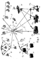
- a remote management system 1A is described, see figure 1 , for a pool of vehicle of the lift truck type 3, which communicate between them by means of a radio link local communication network or LAN (shown schematically in the figure by the arrows F1A) with short range dynamic meshing so that the vehicles 3 communicate with each other and with a base vehicle 5 the data / commands relating to each of them.
- a radio link local communication network or LAN shown schematically in the figure by the arrows F1A
- the radio local network is advantageously and preferably obtained with a digital modulation radio link of type in shift of frequency (FSK) with a coverage range from about 50 meters to about 100 meters.
- FSK shift of frequency
- the local network can also be of a different type, depending on specific utilization requirements.
- the base-vehicle 5 communicates the data / commands to a central server 7 through a geographic communication network F2 obtained by means of a non proprietary WAN network that exploits the GSM national telephone network (it therefore has terrestrial antennas 9, whereof only one is shown in the figure for the sake of simplicity) with a data link in data mode at about 9600 bps or using SMS.
- a geographic communication network F2 obtained by means of a non proprietary WAN network that exploits the GSM national telephone network (it therefore has terrestrial antennas 9, whereof only one is shown in the figure for the sake of simplicity) with a data link in data mode at about 9600 bps or using SMS.
- the base-vehicle 5 can be provided, for example the base can be in a fixed position in the work area.
- Said geographic communication network F2 may be obtained with a different radio link system, for example GSM or UMTS or Satellite or yet another one, as stated above.
- a plurality of sensors and actuators are provided (not shown in figure 1 for the sake of simplicity) to acquire the aforesaid data or to actuate the commands.
- said sensor or actuators - represented schematically with the reference number 100S and 100A in figure 2 - positioned on each vehicle 3, 5 to be managed can serve the function of obtaining data about the monitoring of the state of the general electronics of the vehicle or device, to control the current at the terminals of an electric / electronic and / or signaling device or any impact the vehicle may undergo or measuring ambient temperature or else commanding a key or recognition card, the ignition and verification of the operator's identity, to detect the presence of the operator on the vehicle and / or the correct use of the vehicle or of its devices, or yet other matters.
- Figure 1 also shows a remote management system 1 B for a group of devices or loggers to be managed which are constructed with batteries 13 and associable to each lift truck 3, which batteries 13 communicate between them through a radio local network (shown schematically in the figure by the arrows F1 B) with short range dynamic meshing.
- a radio local network shown schematically in the figure by the arrows F1 B
- a base 15 is positioned in a predetermined location in the work area, for example positioned in the battery charging area, and it is able to connect to each of the batteries 13 as soon as the batteries enter its coverage range.
- the base 15 is also connected to the central server 7 through the long range radio geographic communication network F2.
- the base 15 can be provided, for example the base can be obtained on a battery 13 of the group.
- the remote management system 1 B for the group of batteries 13 is independent of the remote management system 1A for the pool of lift trucks 3, 5; the two remote management systems 1A and 1 B therefore operate on different wavelengths or transmission channels.
- the short-range communication system F1B between the batteries 13 and the system F1A between the lift trucks 3, 5 operate on a same wavelength or transmission channel, providing additional versatility in case of replacement or inversion of the batteries from truck lift to truck lift.
- the data monitored by the batteries 13 can be the total detailed battery life data (for example, the discharging or charging battery counter, the stopped battery counter, the total battery counter, the number of charges made or of micro-charges occurred, the charged or discharged capacity in Amperes, the charging or discharging current) or they can be the charging cycle data (for example, battery voltage, battery current, discharging battery counter, charging battery counter, stopped battery counter, number of charges, charged capacity, discharged capacity, charging current, discharging current, the micro-charges occurred) or yet other data.
- the charging cycle data for example, battery voltage, battery current, discharging battery counter, charging battery counter, stopped battery counter, number of charges, charged capacity, discharged capacity, charging current, discharging current, the micro-charges occurred
- the central server 7 is able to monitor the pools of devices 3, 5 and 13 to be managed storing in a database the data / commands received by each base 5 and 15 and it is connected - in the embodiment shown schematically herein - to a computer server 7A, to a personal computer 7C, to a portable computer 7D and a mobile telephone 7E.
- the computer server 7A displas the state of the device 3, 5 and 13 and / or to send queries to know the situation in real time and / or to create a historical database of the events and / or to publish via Internet some of the data to make them available to other users 7B;
- the personal computer 7C is able to connect both via GSM and serially with access to the programming and to the setting changes of the control of each of the devices 3, 5 and 13;
- the portable computer 7D is able to provide remote management and to connect directly on the device 3, 5 and 13 for local management;
- the mobile telephone 7E is able to send SMS queries to receive in reply from the queried device 3, 5 and 13 the indication of the state or of the value of the requested data, and an enabling or security code can be provided.
- the data and the commands can be made available via Web after access with password to display them in real time from any station with access to the Internet connection.
- central server 7 is described purely by way of indication, since it can be of any other type suitable for the purpose.
- figure 1 shows three additional pools of different vehicles, 23, 33 and 43, of each of which a single vehicle is shown by way of indication.
- a pool of autoclaves 23, a pool of trucks 33 and a pool of excavators 43 are shown; the vehicles of each of these pools are connected to each other and to at least one respective base (not shown in the figure for the sake of simplicity) through respective mesh-type radio communication local networks (not shown in the figure for the sake of simplicity) so that the vehicles of each pool exchange updated data / commands pertaining to functionalities of each of them; each base communicates with the central server 7 through the long range radio geographic communication network F3.
- the vehicles of the pool of trucks 33 and of the pool of excavators 43 are mutually connected through a same local radio communication network (see, by way of example, the arrow F1C) because they are able to operate in a same limited work area.
- the vehicles of the pool of autoclaves 23 are connected between them through a radio local communication network that is independent of those of the pools 33 and 43.
- All vehicles 23, 33 and 43 of said pools are advantageously controlled by a GPS system that determines their position by means of a artificial satellite 90.
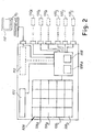
- Figure 2 shows an electronic management and control board 100 for at least one pool of devices and able to be associated to each of the devices, for example able to be associated to the vehicles 3, 5, 23, 33, 43 or to the batteries 13 and to the base 15 described above, comprising, in its main configuration, the following components:
- the processor 108 verifies the update of the receiving data or commands, in order to store only the updated data / commands in the central memory 106; said update is preferably obtained by means of a timer or clock, comparing the time of reception of a data item / command with that of the respective data item / command that resides in the memory 106.
- the first transmitter 102 is a modem for communication in FSK modulation; clearly, said modem may be able to achieve a different type of radio communication, see above.
- the electronic board 100 is installed on each vehicle or device 3, 5, 13, 23, 33, 43 of the pools and it comprises a plurality of sensors 100S and actuators 100A - shown in dashed lines in figure 2 - to acquire the data and respectively to execute the commands on each of them.
- the actuators 100A can be connected to the electronic board 100 through electronic inputs / outputs of different types, for example serial, can bus, digital, analogue or opto-isolated or other types, according to specific requirements or functions, for example a portable computer 7D, to enable a user to operate directly from each device, or a reader - not shown in the figure - for a personalized electronic key or for a transponder electronic card, in order to serve as anti-theft device and as managing device and and to prevent unauthorized operators from using said devices.
- electronic inputs / outputs of different types, for example serial, can bus, digital, analogue or opto-isolated or other types, according to specific requirements or functions, for example a portable computer 7D, to enable a user to operate directly from each device, or a reader - not shown in the figure - for a personalized electronic key or for a transponder electronic card, in order to serve as anti-theft device and as managing device and and to prevent unauthorized operators from using said devices.
- a GPS modem may be included in the electronic board 100, to provide data of geographic position of the device to be managed and implement any electronic key anti-theft system.
- the electronic board 100 comprises a second transmitter 112 - shown in dashed lines in figure 3 - to exchange the data and / or the commands with the central server 7 through the long range radio geographic communication network F2.
- the second transmitter 112 is a GSM communication modem; clearly, said modem 112 can be able to achieve a radio communication of a different type, see above.
- first and the second configuration may advantageously be combined, so that the electronic board 100 is associated to a vehicle or device of the pool and simultaneously serves the base function, as for the base-vehicle 5 of figure 1 .
Landscapes
- Physics & Mathematics (AREA)
- General Physics & Mathematics (AREA)
- Electric Propulsion And Braking For Vehicles (AREA)
- Selective Calling Equipment (AREA)
- Arrangements For Transmission Of Measured Signals (AREA)
- Mobile Radio Communication Systems (AREA)
Abstract
Description
- The present invention relates to a telemetry system for a vehicle pool, specifically industrial vehicles such as lift trucks, and a related method of operation.
- Systems for remotely managing a pool of vehicles by means of communication systems interfaceable with a remote server are known in the art.
- The user-side interface of the remote server can be obtained through different devices, for example through web services in html or via SMS (through a mobile telephone.
- The Italian patent application no.
PR2005A000027 - This management board comprises sensor means, an electronic memory, processing means and means for enabling/disabling the functionalities of the vehicle and a telephone modem for the remote operation of the vehicle.
- The main disadvantage of this electronic board is that the communication of the telephone modem for the remote management of the vehicle can be compromised because of the geographic characteristics of the workplace (for example because of mountains or even of building walls or other obstacles); therefore, a single vehicle may remain isolated for a long time without the ability to communicate with the remote user.
- It should be noted that the efficiency of the remote communication becomes particularly important when alarm signals or signals of vehicle malfunctions requiring timely responses need to be monitored.
- Currently, therefore, in spite of the technological developments, it is problematic and there is a need to provide management systems for an industrial vehicle pool that are simpler and have reduced costs of construction and use, and at the same time are more efficient.
- An object of the invention is to provide a management system with client/server architecture for at least one self-propelled pool of devices that is more efficient and at the same time more economical and simple to construct and use, thus overcoming or reducing at least some of the aforesaid disadvantages of the existing systems.
- Another object of the present invention is to provide an electronic board for a system for managing at least one self-propelled pool of devices that is simpler and more economical than prior art electronic boards.
- Another object of the present invention is to provide a method that allows a better management of at least one self-propelled pool of devices and that is more effective and efficient. According to a first aspect, the invention relates to a system for managing self-propelled vehicle pools with client/server architecture comprising:
- a plurality of devices of at least one pool communicating with each other and with at least one base through at least one mesh-type local communication network to exchange data and / or commands pertaining to each device in the pool;
- at least one sensor or actuator positioned on each of the devices to acquire the aforesaid data or to actuate the commands;
- at least one central server in communication with the base through at least one geographic communication network to exchange the data / commands.
- The terms "data" and "commands" mean any information or command that pertains to the control, the diagnosis and / or the interventions that can be acquired or executed through the sensors and / or the actuators positioned on each of the devices, as is described in greater detail below.
- The term "Local Network" (also called "LAN", Local Area Network)means - in general - a network constituted by computers connected to each other within a delimited space.
- Briefly, the most common types of local area network or LAN for connecting between them a plurality of computers are:
- star, characterized by a central point or star center connected to each computer in the network;
- bus, in which the computers of the network are connected between them by a linear connection via cable;
- ring, in which the computers in the network are connected between them forming a circle so that only one computer at a time can transmit data;
- mesh, in which the computers in the network are connected between them to exchange data pertaining to each computer.
- According to the present invention, the local communication network LAN for connecting the devices of a self-propelled pool is of the mesh type, i.e. each device sends and receives the data / commands pertaining to itself and also those pertaining to all the other vehicles in the pool.
- In a particularly advantageous embodiment of the invention, the mesh-type local network is of the dynamic type, i.e. it is possible to insert new devices in the pool to be controlled, up to a predetermined maximum number.In the preferred embodiment, the dynamic mesh-type local network LAN is obtained by means of a radio link proprietary protocol. Therefore, the data or commands of each device are transmitted when a device enters the range of the radio link of at least one other device or of the base, after verification of the update of the data / commands so that only updated data / commands are transmitted.
- Briefly, a radio link communication is a radio frequency communication able to transmit appropriately encoded information remotely. The capacity available to the transmission depends on the radio spectrum, i.e. on the frequency interval or radio channel, and on the complexity of the modulation used.
- In particular, to a greater encoding complexity corresponds a lesser robustness of the transmission and therefore the need for greater transmission frequency, with the increase in the complexity of the electronics and in the sensitivity to possible interferences.
- With regard to the frequency intervals which can be generally used for radio links, they range from a few MHz to tens of GHz.
- With regard to modulation, it is possible to distinguish a modulation of analogue type in amplitude (AM) or in frequency (FM) or in phase (PM) and a modulation of digital type in amplitude (ASK) or in shift of frequency (FSK) or of phase (PSK).
- In an advantageous embodiment of the invention, the radio link local network or LAN is of the digital type in shift of frequency (FSK), within frequency bands in the public domain; however, the local network may be of a different type, for example PSK or AM, FM or Bluetooth or yet other types.
- The term "geographic communication network" means a communication network able to transmit information at a great distance.
- In the preferred embodiment of the present invention, the geographic communication network is a non proprietary telephonic WAN (Wide Area Network) type network, such as for example a national GSM telephone network, for connecting a plurality of local networks together, and the data exchange is performed in data mode or through the use of SMS.
- A different type of WAN geographic communication network may be used, for example UMTS or Satellite or yet other types.
- In the preferred embodiment of the invention, the devices to be managed are vehicles, such as for example watercraft, transport vehicles, self-propelled vehicles for special uses or industrial vehicles such as lift trucks and earth moving machines or yet others.
- In another embodiment of the invention, the devices to manage are mechanical-electrical devices or loggers associable to each vehicle, for example batteries, electric motors, special uprights, pneumatic hammers, meteorological sensors or others.
- Various combinations of the aforesaid embodiments are possible, in which the industrial vehicles of one or more pools and their mechanical-electrical devices are managed at the same time with respective local communication networks independently or with a single local communication network, whilst one or more bases communicate with a same central server through the aforesaid geographic communication network, see the description below.
- For example, the industrial lift trucks comprise electric motor, stably fastened on each lift truck and replaceable or invertible batteries which are particularly expensive to purchase and maintain.
- Therefore, a local communication network is advantageously provided between the motors and between the batteries of each lift truck (and possibly between other devices implemented on each lift truck) and at least one base, see below.
- In a first configuration according to the invention, the base is positioned on at least one device to be managed, in such a way as to obtain a base-device.
- In this case, communication between the base-device and the central server is advantageously and preferably activated according to a programming defined by the user and communicating the data / commands after verifying their update, in such a way as to communicate only the updated data / commands with it.In particular, the user preferably programs the sending of the data / commands in an immediate manner, advantageously via SMS or other method, i.e. as soon as they are detected by the base, or in a programmed manner in a predefined time interval, or on request or yet automatically when alarm data arrive, see the description below.
- This embodiment is particularly suited to the control of devices that act in a limited work area, substantially lacking "shadow" zones for communication networks, for example a pool of lift trucks working within industrial shed buildings, a pool of earth moving machines in an open quarry, or the like.
- In a second configuration according to the invention, the base is placed in at least one predetermined position in the work area.
- In this case, the geographic communication network between the base and the central server can be activated according to a predetermined setting, for example at regular intervals, or setting communication priorities for particular data (for example alarm signals).
- This embodiment is particularly suited to the control of devices acting in a work area that presents particularly ample or intense "shadow" zones for communication networks, ensuring that the aforesaid base-vehicle is not prevented from communicating with the devices to be managed or with the central server for an excessively prolonged period of time. For example, such a work area can comprise refrigeration cells (within which the signals of the communication networks may be shielded) or it can be a mine with underground tunnels in which the devices to be managed can move and be parked.
- Clearly, a combination of the above mentioned configurations is also possible, for example there may be at least one base-device and at least one fixed base, operating simultaneously or alternatively.
- The aforesaid central server stores the data / commands it receives from the base and it may be of any type able to implement the operations necessary for the management and control by one or more operators or automatically, actuating commands on each device both directly remotely in real time and in a programmed manner, for example a mobile telephone, a personal computer, an operating unit (which itself may be of the server type, i.e. connectable to a plurality of additional user side resources) or other devices, see below.
- According to another aspect, the invention relates to a logic unit associable to a devices of at least one self-propelled pool to be managed which comprises, in the main configuration, a first transmitter for communicating the data and / or the commands through a mesh-type local communication network (LAN); a memory subdivided into a plurality of memory sectors, each able to store data and / or commands pertaining to each device and a processor for processing and storing the data and / or commands.
- The main configuration of this logic unit can be implemented easily and economically in order to obtained additional, different configurations able to manage at least one pool, see the description below.
- According to yet another aspect, the present invention relates to a management method for managing at least one pool of devices comprising at least the following steps:
- a. locally managing each of the devices for obtaining data and / or carrying out commands on each of them;
- b. activating at least one mesh-type local communication network (LAN) to connect the devices of the pool with each other and with at least one base in order to transmit the data and / or the commands pertaining to each device.
- c.activating at least one geographic communication network between the base and at least one central server to transmit the data / commands.
- In a particularly advantageous embodiment of the invention, the activation (b) of the local communication network takes place when one of said devices enters the range of another or of the base, so that a mutual exchange of data / commands pertaining to all the devices in the pool can take place.
- Advantageously, the transmission of the data / commands actually takes place after the mutual verification of their update, so that only updated data / command are transmitted.
- Moreover, the activation (c) of said at least one geographic communication network may take place at the request of a user in remote mode or in automatic, for example according to remotely established settings (when a threshold value or another parameter is exceeded), or in programmed mode within a predefined time interval, or in yet other manners.
- Additionally, the step of locally managing (a) each individual device comprises additional sub-steps for obtaining, storing and / or processing data and / or commands and for monitoring and constantly diagnosing the functionalities or sensitive parts or events and / or safety or for executing commands directly on each of them.
- In another embodiment of the invention, a plurality of local communication networks can be activated independently of each other to achieve separate transmissions among the devices of different pools.
- An advantage of the present invention is that it provides a particularly efficient and reliable management and control system, because the communication of the data / command is improved enormously whilst hugely reducing the likelihood that one of the devices to be managed will remain isolated from the base for a long time.
- Another advantage is that the local communication network is particularly economical both in its construction and maintenance.
- An additional advantage is that said management system is extremely versatile in use, because the functionalities of each device in a pool and / or the functionalities of the loggers associated to said devices can be controlled in a simple, economical manner.
- Another advantage is that it is possible to monitor the devices of one or more self-propelled pools constantly and continuously to create timely and effective alarm warnings. It can also be possible to predict a fault before it occurs, by appropriately setting alarm warnings.
- Moreover, various arrangements can be adopted in order further to improve communication efficiency, for example avoiding using radio link channels subject to strong interference, or encrypting the signals / commands to enhance security, or others.
- Additional advantageous characteristics and embodiments of the method and of the device according to the present invention are indicated in the accompanying dependent claims and they shall be further described hereafter with reference to some non limiting examples of embodiment.
- The present invention can be better understood and its numerous objects and advantages shall be apparent to persons skilled in the art with reference to the accompanying schematic drawings, which show a practical, non limiting example of the invention. In the drawing:
-
figure 1 shows a system for managing a pool of vehicles according to an embodiment of the invention; -
figure 2 shows a logic management unit for a pool of vehicles according to an embodiment of the invention. - In the drawings, in which to equal numbers correspond equal parts in all the different figures, a remote management system 1A is described, see
figure 1 , for a pool of vehicle of the lift truck type 3, which communicate between them by means of a radio link local communication network or LAN (shown schematically in the figure by the arrows F1A) with short range dynamic meshing so that the vehicles 3 communicate with each other and with a base vehicle 5 the data / commands relating to each of them. - The radio local network is advantageously and preferably obtained with a digital modulation radio link of type in shift of frequency (FSK) with a coverage range from about 50 meters to about 100 meters.
- As stated above, the local network can also be of a different type, depending on specific utilization requirements.
- The base-vehicle 5 communicates the data / commands to a central server 7 through a geographic communication network F2 obtained by means of a non proprietary WAN network that exploits the GSM national telephone network (it therefore has terrestrial antennas 9, whereof only one is shown in the figure for the sake of simplicity) with a data link in data mode at about 9600 bps or using SMS.
- In any case, different configurations of the base-vehicle 5 can be provided, for example the base can be in a fixed position in the work area.
- Said geographic communication network F2 may be obtained with a different radio link system, for example GSM or UMTS or Satellite or yet another one, as stated above.
- In this way it is possible to manage remotely, even at a great distance, the pool of lift trucks 3.
- On each vehicle 3, 5 of the pool, a plurality of sensors and actuators are provided (not shown in
figure 1 for the sake of simplicity) to acquire the aforesaid data or to actuate the commands. - Indicatively, said sensor or actuators - represented schematically with the
reference number 100S and 100A infigure 2 - positioned on each vehicle 3, 5 to be managed can serve the function of obtaining data about the monitoring of the state of the general electronics of the vehicle or device, to control the current at the terminals of an electric / electronic and / or signaling device or any impact the vehicle may undergo or measuring ambient temperature or else commanding a key or recognition card, the ignition and verification of the operator's identity, to detect the presence of the operator on the vehicle and / or the correct use of the vehicle or of its devices, or yet other matters. - The aforesaid list is indicative of the type of sensor or actuators and it is no way to be construed as limiting, for the sensors and actuators can be of countless types depending on specific requirements.
-
Figure 1 also shows aremote management system 1 B for a group of devices or loggers to be managed which are constructed withbatteries 13 and associable to each lift truck 3, whichbatteries 13 communicate between them through a radio local network (shown schematically in the figure by the arrows F1 B) with short range dynamic meshing. - In this case, a
base 15 is positioned in a predetermined location in the work area, for example positioned in the battery charging area, and it is able to connect to each of thebatteries 13 as soon as the batteries enter its coverage range. - The
base 15 is also connected to the central server 7 through the long range radio geographic communication network F2. - Clearly, a different number or different configurations of the base 15 can be provided, for example the base can be obtained on a
battery 13 of the group. - In one embodiment, the
remote management system 1 B for the group ofbatteries 13 is independent of the remote management system 1A for the pool of lift trucks 3, 5; the tworemote management systems 1A and 1 B therefore operate on different wavelengths or transmission channels.In another preferable embodiment, the short-range communication system F1B between thebatteries 13 and the system F1A between the lift trucks 3, 5 operate on a same wavelength or transmission channel, providing additional versatility in case of replacement or inversion of the batteries from truck lift to truck lift. - In particular, in this latter case, advantageously there is a plurality of memory sectors or addresses of a central memory associated to each device and able to store the information of each of them, see below.
- Indicatively, the data monitored by the
batteries 13 can be the total detailed battery life data (for example, the discharging or charging battery counter, the stopped battery counter, the total battery counter, the number of charges made or of micro-charges occurred, the charged or discharged capacity in Amperes, the charging or discharging current) or they can be the charging cycle data (for example, battery voltage, battery current, discharging battery counter, charging battery counter, stopped battery counter, number of charges, charged capacity, discharged capacity, charging current, discharging current, the micro-charges occurred) or yet other data. - The central server 7 is able to monitor the pools of
devices 3, 5 and 13 to be managed storing in a database the data / commands received by eachbase 5 and 15 and it is connected - in the embodiment shown schematically herein - to a computer server 7A, to a personal computer 7C, to a portable computer 7D and a mobile telephone 7E. - In particular, the computer server 7A displas the state of the
device 3, 5 and 13 and / or to send queries to know the situation in real time and / or to create a historical database of the events and / or to publish via Internet some of the data to make them available to other users 7B; the personal computer 7C is able to connect both via GSM and serially with access to the programming and to the setting changes of the control of each of thedevices 3, 5 and 13; the portable computer 7D is able to provide remote management and to connect directly on thedevice 3, 5 and 13 for local management; the mobile telephone 7E is able to send SMS queries to receive in reply from the querieddevice 3, 5 and 13 the indication of the state or of the value of the requested data, and an enabling or security code can be provided. - Lastly, the data and the commands can be made available via Web after access with password to display them in real time from any station with access to the Internet connection.
- Clearly, the aforesaid central server 7 is described purely by way of indication, since it can be of any other type suitable for the purpose.
- Moreover,
figure 1 shows three additional pools of different vehicles, 23, 33 and 43, of each of which a single vehicle is shown by way of indication. - In particular, a pool of
autoclaves 23, a pool oftrucks 33 and a pool ofexcavators 43 are shown; the vehicles of each of these pools are connected to each other and to at least one respective base (not shown in the figure for the sake of simplicity) through respective mesh-type radio communication local networks (not shown in the figure for the sake of simplicity) so that the vehicles of each pool exchange updated data / commands pertaining to functionalities of each of them; each base communicates with the central server 7 through the long range radio geographic communication network F3. - More in particular, the vehicles of the pool of
trucks 33 and of the pool ofexcavators 43 are mutually connected through a same local radio communication network (see, by way of example, the arrow F1C) because they are able to operate in a same limited work area. - Instead, the vehicles of the pool of
autoclaves 23 are connected between them through a radio local communication network that is independent of those of thepools - All
vehicles artificial satellite 90. -
Figure 2 shows an electronic management andcontrol board 100 for at least one pool of devices and able to be associated to each of the devices, for example able to be associated to thevehicles batteries 13 and to the base 15 described above, comprising, in its main configuration, the following components: - a
first transmitter 102 for exchanging data and / or commands through the radio local communication network F1A or F1B or F1C; - a
central memory 106 divided into a number "n" of memory sectors or addresses 106A, 106b, 106c, ... 106n, each sector storing independently updated data and / or commands pertaining to each device or vehicle, the maximum number "n" of memory sectors corresponds to the maximum number of devices manageable by the system; - a
processor 108 for processing and storing the data and / or commands with a service RAM memory 108B on which the processing data / commands are stored. - In particular, the
processor 108 verifies the update of the receiving data or commands, in order to store only the updated data / commands in thecentral memory 106; said update is preferably obtained by means of a timer or clock, comparing the time of reception of a data item / command with that of the respective data item / command that resides in thememory 106. - It should also be noted that, by associating a different vehicle or device to each
memory sector 106A, 106b, 106c, 106n, it is advantageously possible to use a same wavelength or transmission channel for communication through the mesh-type local network. In a particularly advantageous embodiment, thefirst transmitter 102 is a modem for communication in FSK modulation; clearly, said modem may be able to achieve a different type of radio communication, see above. - It is also possible to provide an electrical power supply battery - not shown in the figure for the sake of simplicity - to allow the
electronic board 100 to operate independently of the power supply of the device whereon it is associated. - In a first configuration, the
electronic board 100 is installed on each vehicle ordevice actuators 100A - shown in dashed lines infigure 2 - to acquire the data and respectively to execute the commands on each of them. - It should be noted that the
actuators 100A can be connected to theelectronic board 100 through electronic inputs / outputs of different types, for example serial, can bus, digital, analogue or opto-isolated or other types, according to specific requirements or functions, for example a portable computer 7D, to enable a user to operate directly from each device, or a reader - not shown in the figure - for a personalized electronic key or for a transponder electronic card, in order to serve as anti-theft device and as managing device and and to prevent unauthorized operators from using said devices. - Additionally, a GPS modem may be included in the
electronic board 100, to provide data of geographic position of the device to be managed and implement any electronic key anti-theft system. - In a second configuration as a base, the
electronic board 100 comprises a second transmitter 112 - shown in dashed lines in figure 3 - to exchange the data and / or the commands with the central server 7 through the long range radio geographic communication network F2. - In a particularly advantageous embodiment, the
second transmitter 112 is a GSM communication modem; clearly, saidmodem 112 can be able to achieve a radio communication of a different type, see above. - It should be noted that the first and the second configuration may advantageously be combined, so that the
electronic board 100 is associated to a vehicle or device of the pool and simultaneously serves the base function, as for the base-vehicle 5 offigure 1 . - In this way it is possible to obtain an electronic board whose construction is particularly simple and that is extremely versatile, because it can be installed on each element of different groups or pools to be controlled.
- What is illustrated represents merely possible non limiting embodiments of the invention, which may vary in its forms and arrangements without thereby departing from the scope of the concept on which the invention is based. The presence of any reference numbers in the appended claims serves solely the purpose of facilitating the reading of the claims in light of the preceding description and of the accompanying drawings and does not limit in any way its scope of the protection.
Claims (15)
- A management system with client / server architecture for at least one self-propelled pool of devices to be managed, characterized in that it comprises:a. a plurality of said devices communicating with each other and with at least one base through at least one mesh-type local communication network to exchange data and / or commands pertaining to each of them;b. at least one sensor or actuator positioned on each of said devices to acquire the aforesaid data or to actuate the commands;c. at least one central server in communication with said at least one base through a geographic communication network to exchange said data / commands.
- The remote management system according to claim 1, characterized in that said at least one mesh-type local communication network is formed so that each of said devices or said at least one base sends or receives said updated data / commands pertaining to itself and to all said devices or bases every time one of said devices or bases enters in the action range or coverage range of another device or base
- The remote management system according to claim 1 and / or 2, characterized in that said at least one local network is of the dynamic mesh type to allow the insertion of new devices to be controlled in said pool.
- The remote management system according to at least one of the claims 1 to 3 and / or 2, characterized in that said at least one local communication network is obtained by means of a radio link local network.
- The remote management system according to at least one or more of the previous claims, characterized in that said at least one local communication network is able to exchange said data or commands within a short coverage range or a short action range.
- The remote management system according to claim 1 and / or 5, characterized in that said at least one base is positioned on at least one of said devices or placed in a predetermined position in the working area.
- The remote management system according to claim 1, characterized in that said geographic communication network is formed by a long range communication system.
- The remote management system according to at least one of the previous claims, characterized in that said vehicles are industrial vehicles or they are mechanical-electrical devices associable to each of said industrial vehicles.
- The remote management system according to at least one of the previous claims, characterized in that it comprises two or more of said mesh-type local communication networks managing and controlling a plurality of groups or pools of said devices in the same working area.
- The remote management system according to at least claim 9, characterized in that each of said groups or pools comprises said at least one base in order to communicate data / commands to said at least one central server through said at least one geographic communication network.
- An electronic board for remote management associable to each device of at least one self-propelled pool, characterized in that it comprises:- at least a first transmitter for communicating data and / or commands through a mesh-type local communication network;- at least one central memory divided into a plurality of memory sectors each able to store said data and / or commands pertaining to each of said devices;- a processor for processing and storing said data / commands.
- The electronic unit according to claim 11, characterized in that said processor stores said data / command in said central memory after verifying the update of said data / commands through a timer or clock or the like.
- The electronic unit according to at least one of the claims 11 to 13, characterized in that it comprises, in combination or as an alternative, at least one of the following:- at least one sensor and / or one actuator to acquire said data and respectively to execute said commands on each of said devices,- a reader for a personalized electronic key or for an electronic card of the transponder type;- a user-side interface for enabling a user to operate directly from each of said devices, for example a portable computer or another device;- a plurality of electronic inputs / outputs, for example serial, can bus, digital, analogue or opto-isolated or others;- a connection with a data acquisition system through GPS,- a second transmitter for exchanging said data / commands with a central server through a long range geographic communication network.
- A method for managing at least one self-propelled pool characterized in that it comprises the following steps:- locally managing each of said devices for sensing data and / or carrying out commands on each of them;- activating at least one mesh-type local communication network to connect said devices between them and with at least one base in order to transmit said updated data and / or commands pertaining to each device;- activating at least one long action range geographic communication network between said at least one base and at least one central server in order to exchange said data / commands to manage or to control in remote mode said self-propelled pool.
- The method according to claim 14, characterized in that the activation (b) of said at least one local communication network occurs automatically when at least one of said devices enters the action range of another device or of said at least one base.
Applications Claiming Priority (1)
| Application Number | Priority Date | Filing Date | Title |
|---|---|---|---|
| IT000249A ITFI20070249A1 (en) | 2007-11-06 | 2007-11-06 | "TELEMETRY SYSTEM FOR A VEHICLE PARK" |
Publications (2)
| Publication Number | Publication Date |
|---|---|
| EP2058718A1 true EP2058718A1 (en) | 2009-05-13 |
| EP2058718B1 EP2058718B1 (en) | 2011-04-20 |
Family
ID=40314616
Family Applications (1)
| Application Number | Title | Priority Date | Filing Date |
|---|---|---|---|
| EP08425709A Not-in-force EP2058718B1 (en) | 2007-11-06 | 2008-11-05 | A telemetry system for a vehicle pool |
Country Status (5)
| Country | Link |
|---|---|
| EP (1) | EP2058718B1 (en) |
| AT (1) | ATE506641T1 (en) |
| DE (1) | DE602008006328D1 (en) |
| ES (1) | ES2361793T3 (en) |
| IT (1) | ITFI20070249A1 (en) |
Cited By (1)
| Publication number | Priority date | Publication date | Assignee | Title |
|---|---|---|---|---|
| CN111585636A (en) * | 2020-04-17 | 2020-08-25 | 云南师范大学 | Vehicle management system based on big dipper and Lora data transfer radio station |
Citations (3)
| Publication number | Priority date | Publication date | Assignee | Title |
|---|---|---|---|---|
| US20060026101A1 (en) * | 2003-06-19 | 2006-02-02 | Hiroshi Ogura | Work support and management system for working machine |
| WO2007104152A2 (en) | 2006-03-14 | 2007-09-20 | Jamie Hackett | Long-range radio frequency receiver-controller module and wireless control system comprising same |
| WO2008066753A1 (en) * | 2006-11-22 | 2008-06-05 | Solidica, Inc. | Diagnostic and telematic system |
-
2007
- 2007-11-06 IT IT000249A patent/ITFI20070249A1/en unknown
-
2008
- 2008-11-05 EP EP08425709A patent/EP2058718B1/en not_active Not-in-force
- 2008-11-05 AT AT08425709T patent/ATE506641T1/en not_active IP Right Cessation
- 2008-11-05 DE DE602008006328T patent/DE602008006328D1/en active Active
- 2008-11-05 ES ES08425709T patent/ES2361793T3/en active Active
Patent Citations (3)
| Publication number | Priority date | Publication date | Assignee | Title |
|---|---|---|---|---|
| US20060026101A1 (en) * | 2003-06-19 | 2006-02-02 | Hiroshi Ogura | Work support and management system for working machine |
| WO2007104152A2 (en) | 2006-03-14 | 2007-09-20 | Jamie Hackett | Long-range radio frequency receiver-controller module and wireless control system comprising same |
| WO2008066753A1 (en) * | 2006-11-22 | 2008-06-05 | Solidica, Inc. | Diagnostic and telematic system |
Cited By (2)
| Publication number | Priority date | Publication date | Assignee | Title |
|---|---|---|---|---|
| CN111585636A (en) * | 2020-04-17 | 2020-08-25 | 云南师范大学 | Vehicle management system based on big dipper and Lora data transfer radio station |
| CN111585636B (en) * | 2020-04-17 | 2021-11-09 | 云南师范大学 | Vehicle management system based on big dipper and Lora data transfer radio station |
Also Published As
| Publication number | Publication date |
|---|---|
| EP2058718B1 (en) | 2011-04-20 |
| ATE506641T1 (en) | 2011-05-15 |
| DE602008006328D1 (en) | 2011-06-01 |
| ITFI20070249A1 (en) | 2009-05-07 |
| ES2361793T3 (en) | 2011-06-22 |
Similar Documents
| Publication | Publication Date | Title |
|---|---|---|
| CN108495736B (en) | Anti-theft module for a battery-operated electric power tool and battery-operated electric power tool with an anti-theft module | |
| CN105899378B (en) | Method for configuring tyre pressure sensor | |
| US7825793B1 (en) | Remote monitoring and control system | |
| US20170249792A1 (en) | Method for remotely controlling at least a first function of a safety device of a vehicle | |
| CN100576255C (en) | Automatically select the method for radio operational mode | |
| CN103138789B (en) | Vehicle portable device and information communication system | |
| US9354627B2 (en) | Control method, control computer program, and control system for work machine | |
| CN104806085A (en) | Intelligent door lock system and intelligent reminding method | |
| US20080270074A1 (en) | User customized machine data acquisition system | |
| CN103688494A (en) | Communication system, relay device, and communication method | |
| CN102656736A (en) | Electric battery for vehicles | |
| US20130289752A1 (en) | Method of Operating a Mobile Control Unit of a Home Automation Installation | |
| CN104870266A (en) | Tire theft alarm system | |
| CN101164090A (en) | Method of selecting data communication provider in a field device | |
| CN210694006U (en) | NB-IoT intelligent safety well lid control device | |
| CN101624038B (en) | Vehicle real-time wireless sensing monitoring system | |
| CN105530602A (en) | Wireless communication equipment, remote control center, monitoring control system and method | |
| EP2058718B1 (en) | A telemetry system for a vehicle pool | |
| CN104838356B (en) | Work machine, management system and management method | |
| CN102189979A (en) | System and method for integrating tire pressure monitoring and remote key-free entering | |
| GB2453521A (en) | Data transmission from a vehicle and network regulation | |
| WO2007039792A3 (en) | Vehicle monitoring | |
| CN102057404A (en) | Mobile identification transmitter in a safety system | |
| CN109644336A (en) | It is transmitted with the automatic safe data of motor vehicles | |
| US6037875A (en) | Method and apparatus for providing notification of the falling motion of a tree |
Legal Events
| Date | Code | Title | Description |
|---|---|---|---|
| PUAI | Public reference made under article 153(3) epc to a published international application that has entered the european phase |
Free format text: ORIGINAL CODE: 0009012 |
|
| AK | Designated contracting states |
Kind code of ref document: A1 Designated state(s): AT BE BG CH CY CZ DE DK EE ES FI FR GB GR HR HU IE IS IT LI LT LU LV MC MT NL NO PL PT RO SE SI SK TR |
|
| AX | Request for extension of the european patent |
Extension state: AL BA MK RS |
|
| 17P | Request for examination filed |
Effective date: 20091105 |
|
| 17Q | First examination report despatched |
Effective date: 20091215 |
|
| AKX | Designation fees paid |
Designated state(s): AT BE BG CH CY CZ DE DK EE ES FI FR GB GR HR HU IE IS IT LI LT LU LV MC MT NL NO PL PT RO SE SI SK TR |
|
| GRAP | Despatch of communication of intention to grant a patent |
Free format text: ORIGINAL CODE: EPIDOSNIGR1 |
|
| GRAS | Grant fee paid |
Free format text: ORIGINAL CODE: EPIDOSNIGR3 |
|
| GRAA | (expected) grant |
Free format text: ORIGINAL CODE: 0009210 |
|
| AK | Designated contracting states |
Kind code of ref document: B1 Designated state(s): AT BE BG CH CY CZ DE DK EE ES FI FR GB GR HR HU IE IS IT LI LT LU LV MC MT NL NO PL PT RO SE SI SK TR |
|
| REG | Reference to a national code |
Ref country code: GB Ref legal event code: FG4D |
|
| REG | Reference to a national code |
Ref country code: CH Ref legal event code: EP |
|
| REG | Reference to a national code |
Ref country code: IE Ref legal event code: FG4D |
|
| REF | Corresponds to: |
Ref document number: 602008006328 Country of ref document: DE Date of ref document: 20110601 Kind code of ref document: P |
|
| REG | Reference to a national code |
Ref country code: DE Ref legal event code: R096 Ref document number: 602008006328 Country of ref document: DE Effective date: 20110601 |
|
| REG | Reference to a national code |
Ref country code: ES Ref legal event code: FG2A Ref document number: 2361793 Country of ref document: ES Kind code of ref document: T3 Effective date: 20110622 |
|
| REG | Reference to a national code |
Ref country code: SE Ref legal event code: TRGR |
|
| REG | Reference to a national code |
Ref country code: NL Ref legal event code: VDEP Effective date: 20110420 |
|
| LTIE | Lt: invalidation of european patent or patent extension |
Effective date: 20110420 |
|
| PG25 | Lapsed in a contracting state [announced via postgrant information from national office to epo] |
Ref country code: PT Free format text: LAPSE BECAUSE OF FAILURE TO SUBMIT A TRANSLATION OF THE DESCRIPTION OR TO PAY THE FEE WITHIN THE PRESCRIBED TIME-LIMIT Effective date: 20110822 Ref country code: LT Free format text: LAPSE BECAUSE OF FAILURE TO SUBMIT A TRANSLATION OF THE DESCRIPTION OR TO PAY THE FEE WITHIN THE PRESCRIBED TIME-LIMIT Effective date: 20110420 Ref country code: HR Free format text: LAPSE BECAUSE OF FAILURE TO SUBMIT A TRANSLATION OF THE DESCRIPTION OR TO PAY THE FEE WITHIN THE PRESCRIBED TIME-LIMIT Effective date: 20110420 Ref country code: NO Free format text: LAPSE BECAUSE OF FAILURE TO SUBMIT A TRANSLATION OF THE DESCRIPTION OR TO PAY THE FEE WITHIN THE PRESCRIBED TIME-LIMIT Effective date: 20110720 |
|
| PG25 | Lapsed in a contracting state [announced via postgrant information from national office to epo] |
Ref country code: CY Free format text: LAPSE BECAUSE OF FAILURE TO SUBMIT A TRANSLATION OF THE DESCRIPTION OR TO PAY THE FEE WITHIN THE PRESCRIBED TIME-LIMIT Effective date: 20110420 Ref country code: AT Free format text: LAPSE BECAUSE OF FAILURE TO SUBMIT A TRANSLATION OF THE DESCRIPTION OR TO PAY THE FEE WITHIN THE PRESCRIBED TIME-LIMIT Effective date: 20110420 Ref country code: IS Free format text: LAPSE BECAUSE OF FAILURE TO SUBMIT A TRANSLATION OF THE DESCRIPTION OR TO PAY THE FEE WITHIN THE PRESCRIBED TIME-LIMIT Effective date: 20110820 Ref country code: GR Free format text: LAPSE BECAUSE OF FAILURE TO SUBMIT A TRANSLATION OF THE DESCRIPTION OR TO PAY THE FEE WITHIN THE PRESCRIBED TIME-LIMIT Effective date: 20110721 Ref country code: LV Free format text: LAPSE BECAUSE OF FAILURE TO SUBMIT A TRANSLATION OF THE DESCRIPTION OR TO PAY THE FEE WITHIN THE PRESCRIBED TIME-LIMIT Effective date: 20110420 Ref country code: SI Free format text: LAPSE BECAUSE OF FAILURE TO SUBMIT A TRANSLATION OF THE DESCRIPTION OR TO PAY THE FEE WITHIN THE PRESCRIBED TIME-LIMIT Effective date: 20110420 Ref country code: FI Free format text: LAPSE BECAUSE OF FAILURE TO SUBMIT A TRANSLATION OF THE DESCRIPTION OR TO PAY THE FEE WITHIN THE PRESCRIBED TIME-LIMIT Effective date: 20110420 |
|
| PG25 | Lapsed in a contracting state [announced via postgrant information from national office to epo] |
Ref country code: NL Free format text: LAPSE BECAUSE OF FAILURE TO SUBMIT A TRANSLATION OF THE DESCRIPTION OR TO PAY THE FEE WITHIN THE PRESCRIBED TIME-LIMIT Effective date: 20110420 |
|
| PG25 | Lapsed in a contracting state [announced via postgrant information from national office to epo] |
Ref country code: CZ Free format text: LAPSE BECAUSE OF FAILURE TO SUBMIT A TRANSLATION OF THE DESCRIPTION OR TO PAY THE FEE WITHIN THE PRESCRIBED TIME-LIMIT Effective date: 20110420 Ref country code: EE Free format text: LAPSE BECAUSE OF FAILURE TO SUBMIT A TRANSLATION OF THE DESCRIPTION OR TO PAY THE FEE WITHIN THE PRESCRIBED TIME-LIMIT Effective date: 20110420 |
|
| PGFP | Annual fee paid to national office [announced via postgrant information from national office to epo] |
Ref country code: SE Payment date: 20111124 Year of fee payment: 4 |
|
| PLBE | No opposition filed within time limit |
Free format text: ORIGINAL CODE: 0009261 |
|
| STAA | Information on the status of an ep patent application or granted ep patent |
Free format text: STATUS: NO OPPOSITION FILED WITHIN TIME LIMIT |
|
| PG25 | Lapsed in a contracting state [announced via postgrant information from national office to epo] |
Ref country code: PL Free format text: LAPSE BECAUSE OF FAILURE TO SUBMIT A TRANSLATION OF THE DESCRIPTION OR TO PAY THE FEE WITHIN THE PRESCRIBED TIME-LIMIT Effective date: 20110420 Ref country code: DK Free format text: LAPSE BECAUSE OF FAILURE TO SUBMIT A TRANSLATION OF THE DESCRIPTION OR TO PAY THE FEE WITHIN THE PRESCRIBED TIME-LIMIT Effective date: 20110420 Ref country code: RO Free format text: LAPSE BECAUSE OF FAILURE TO SUBMIT A TRANSLATION OF THE DESCRIPTION OR TO PAY THE FEE WITHIN THE PRESCRIBED TIME-LIMIT Effective date: 20110420 Ref country code: SK Free format text: LAPSE BECAUSE OF FAILURE TO SUBMIT A TRANSLATION OF THE DESCRIPTION OR TO PAY THE FEE WITHIN THE PRESCRIBED TIME-LIMIT Effective date: 20110420 |
|
| 26N | No opposition filed |
Effective date: 20120123 |
|
| REG | Reference to a national code |
Ref country code: DE Ref legal event code: R097 Ref document number: 602008006328 Country of ref document: DE Effective date: 20120123 |
|
| PG25 | Lapsed in a contracting state [announced via postgrant information from national office to epo] |
Ref country code: MC Free format text: LAPSE BECAUSE OF NON-PAYMENT OF DUE FEES Effective date: 20111130 |
|
| REG | Reference to a national code |
Ref country code: IE Ref legal event code: MM4A |
|
| PG25 | Lapsed in a contracting state [announced via postgrant information from national office to epo] |
Ref country code: IE Free format text: LAPSE BECAUSE OF NON-PAYMENT OF DUE FEES Effective date: 20111105 |
|
| PG25 | Lapsed in a contracting state [announced via postgrant information from national office to epo] |
Ref country code: MT Free format text: LAPSE BECAUSE OF FAILURE TO SUBMIT A TRANSLATION OF THE DESCRIPTION OR TO PAY THE FEE WITHIN THE PRESCRIBED TIME-LIMIT Effective date: 20110420 |
|
| PG25 | Lapsed in a contracting state [announced via postgrant information from national office to epo] |
Ref country code: LU Free format text: LAPSE BECAUSE OF NON-PAYMENT OF DUE FEES Effective date: 20111105 |
|
| PG25 | Lapsed in a contracting state [announced via postgrant information from national office to epo] |
Ref country code: BG Free format text: LAPSE BECAUSE OF FAILURE TO SUBMIT A TRANSLATION OF THE DESCRIPTION OR TO PAY THE FEE WITHIN THE PRESCRIBED TIME-LIMIT Effective date: 20110720 |
|
| REG | Reference to a national code |
Ref country code: CH Ref legal event code: PL |
|
| PG25 | Lapsed in a contracting state [announced via postgrant information from national office to epo] |
Ref country code: LI Free format text: LAPSE BECAUSE OF NON-PAYMENT OF DUE FEES Effective date: 20121130 Ref country code: CH Free format text: LAPSE BECAUSE OF NON-PAYMENT OF DUE FEES Effective date: 20121130 Ref country code: SE Free format text: LAPSE BECAUSE OF NON-PAYMENT OF DUE FEES Effective date: 20121106 |
|
| PG25 | Lapsed in a contracting state [announced via postgrant information from national office to epo] |
Ref country code: TR Free format text: LAPSE BECAUSE OF FAILURE TO SUBMIT A TRANSLATION OF THE DESCRIPTION OR TO PAY THE FEE WITHIN THE PRESCRIBED TIME-LIMIT Effective date: 20110420 |
|
| PG25 | Lapsed in a contracting state [announced via postgrant information from national office to epo] |
Ref country code: HU Free format text: LAPSE BECAUSE OF FAILURE TO SUBMIT A TRANSLATION OF THE DESCRIPTION OR TO PAY THE FEE WITHIN THE PRESCRIBED TIME-LIMIT Effective date: 20110420 |
|
| REG | Reference to a national code |
Ref country code: FR Ref legal event code: PLFP Year of fee payment: 8 |
|
| REG | Reference to a national code |
Ref country code: FR Ref legal event code: PLFP Year of fee payment: 9 |
|
| PGFP | Annual fee paid to national office [announced via postgrant information from national office to epo] |
Ref country code: GB Payment date: 20161130 Year of fee payment: 9 Ref country code: FR Payment date: 20161129 Year of fee payment: 9 |
|
| PGFP | Annual fee paid to national office [announced via postgrant information from national office to epo] |
Ref country code: BE Payment date: 20161129 Year of fee payment: 9 Ref country code: ES Payment date: 20161125 Year of fee payment: 9 |
|
| PGFP | Annual fee paid to national office [announced via postgrant information from national office to epo] |
Ref country code: DE Payment date: 20170126 Year of fee payment: 9 |
|
| PGFP | Annual fee paid to national office [announced via postgrant information from national office to epo] |
Ref country code: IT Payment date: 20171129 Year of fee payment: 10 |
|
| REG | Reference to a national code |
Ref country code: DE Ref legal event code: R119 Ref document number: 602008006328 Country of ref document: DE |
|
| GBPC | Gb: european patent ceased through non-payment of renewal fee |
Effective date: 20171105 |
|
| REG | Reference to a national code |
Ref country code: FR Ref legal event code: ST Effective date: 20180731 Ref country code: BE Ref legal event code: MM Effective date: 20171130 |
|
| PG25 | Lapsed in a contracting state [announced via postgrant information from national office to epo] |
Ref country code: FR Free format text: LAPSE BECAUSE OF NON-PAYMENT OF DUE FEES Effective date: 20171130 Ref country code: DE Free format text: LAPSE BECAUSE OF NON-PAYMENT OF DUE FEES Effective date: 20180602 |
|
| PG25 | Lapsed in a contracting state [announced via postgrant information from national office to epo] |
Ref country code: GB Free format text: LAPSE BECAUSE OF NON-PAYMENT OF DUE FEES Effective date: 20171105 Ref country code: BE Free format text: LAPSE BECAUSE OF NON-PAYMENT OF DUE FEES Effective date: 20171130 |
|
| REG | Reference to a national code |
Ref country code: ES Ref legal event code: FD2A Effective date: 20181226 |
|
| PG25 | Lapsed in a contracting state [announced via postgrant information from national office to epo] |
Ref country code: ES Free format text: LAPSE BECAUSE OF NON-PAYMENT OF DUE FEES Effective date: 20171106 |
|
| PG25 | Lapsed in a contracting state [announced via postgrant information from national office to epo] |
Ref country code: IT Free format text: LAPSE BECAUSE OF NON-PAYMENT OF DUE FEES Effective date: 20181105 |