EP2058678A2 - In-vehicle radar device - Google Patents
In-vehicle radar device Download PDFInfo
- Publication number
- EP2058678A2 EP2058678A2 EP08167755A EP08167755A EP2058678A2 EP 2058678 A2 EP2058678 A2 EP 2058678A2 EP 08167755 A EP08167755 A EP 08167755A EP 08167755 A EP08167755 A EP 08167755A EP 2058678 A2 EP2058678 A2 EP 2058678A2
- Authority
- EP
- European Patent Office
- Prior art keywords
- target
- vehicle
- intensity
- electromagnetic wave
- radar device
- Prior art date
- Legal status (The legal status is an assumption and is not a legal conclusion. Google has not performed a legal analysis and makes no representation as to the accuracy of the status listed.)
- Granted
Links
Images


Classifications
-
- G—PHYSICS
- G01—MEASURING; TESTING
- G01S—RADIO DIRECTION-FINDING; RADIO NAVIGATION; DETERMINING DISTANCE OR VELOCITY BY USE OF RADIO WAVES; LOCATING OR PRESENCE-DETECTING BY USE OF THE REFLECTION OR RERADIATION OF RADIO WAVES; ANALOGOUS ARRANGEMENTS USING OTHER WAVES
- G01S17/00—Systems using the reflection or reradiation of electromagnetic waves other than radio waves, e.g. lidar systems
- G01S17/88—Lidar systems specially adapted for specific applications
- G01S17/93—Lidar systems specially adapted for specific applications for anti-collision purposes
- G01S17/931—Lidar systems specially adapted for specific applications for anti-collision purposes of land vehicles
-
- G—PHYSICS
- G01—MEASURING; TESTING
- G01S—RADIO DIRECTION-FINDING; RADIO NAVIGATION; DETERMINING DISTANCE OR VELOCITY BY USE OF RADIO WAVES; LOCATING OR PRESENCE-DETECTING BY USE OF THE REFLECTION OR RERADIATION OF RADIO WAVES; ANALOGOUS ARRANGEMENTS USING OTHER WAVES
- G01S17/00—Systems using the reflection or reradiation of electromagnetic waves other than radio waves, e.g. lidar systems
- G01S17/02—Systems using the reflection of electromagnetic waves other than radio waves
- G01S17/06—Systems determining position data of a target
- G01S17/42—Simultaneous measurement of distance and other co-ordinates
-
- G—PHYSICS
- G01—MEASURING; TESTING
- G01S—RADIO DIRECTION-FINDING; RADIO NAVIGATION; DETERMINING DISTANCE OR VELOCITY BY USE OF RADIO WAVES; LOCATING OR PRESENCE-DETECTING BY USE OF THE REFLECTION OR RERADIATION OF RADIO WAVES; ANALOGOUS ARRANGEMENTS USING OTHER WAVES
- G01S7/00—Details of systems according to groups G01S13/00, G01S15/00, G01S17/00
- G01S7/48—Details of systems according to groups G01S13/00, G01S15/00, G01S17/00 of systems according to group G01S17/00
- G01S7/4802—Details of systems according to groups G01S13/00, G01S15/00, G01S17/00 of systems according to group G01S17/00 using analysis of echo signal for target characterisation; Target signature; Target cross-section
-
- G—PHYSICS
- G01—MEASURING; TESTING
- G01S—RADIO DIRECTION-FINDING; RADIO NAVIGATION; DETERMINING DISTANCE OR VELOCITY BY USE OF RADIO WAVES; LOCATING OR PRESENCE-DETECTING BY USE OF THE REFLECTION OR RERADIATION OF RADIO WAVES; ANALOGOUS ARRANGEMENTS USING OTHER WAVES
- G01S7/00—Details of systems according to groups G01S13/00, G01S15/00, G01S17/00
- G01S7/48—Details of systems according to groups G01S13/00, G01S15/00, G01S17/00 of systems according to group G01S17/00
- G01S7/497—Means for monitoring or calibrating
- G01S7/4972—Alignment of sensor
Definitions
- the present invention relates to an in-vehicle radar device mounted on a vehicle such as automobile (hereinafter referred to as a vehicle).
- An in-vehicle radar device is a radar device of a so-called pulse radar type for emitting electromagnetic waves such as an electric wave and light towards the front side of a vehicle in a bundle (pulse form), and detecting information including a distance and a direction to an obstacle at the front side of an own vehicle based on the reflected wave from the front side of the vehicle.
- An electric field and a magnetic field include a static field, which is temporally constant, and a wave field which temporally fluctuates and propagates to a distant in space, where the wave field is referred to as a "electromagnetic wave".
- the typical electromagnetic wave is an electric wave, but light, X-ray and the like are also electromagnetic waves.
- the electromagnetic wave of pulse form emitted from a transmission unit of the in-vehicle radar device is reflected by a body surface (rear reflector or reflecting site corresponding thereto) of an obstacle at front of the own vehicle (hereinafter referred to as a leading vehicle for the sake of convenience), and received by a reception unit of the in-vehicle radar device.
- a body surface rear reflector or reflecting site corresponding thereto
- the direction of the leading vehicle with the own vehicle (vehicle installed with in-vehicle radar device) as a reference is obtained in the emitting direction of the pulse-form electromagnetic wave, and for instance, the direction of the leading vehicle is obtained as 0 degrees if the emitting direction is 0 degrees (i.e., advancing direction of the own vehicle).
- the laser beam which is one type of electromagnetic wave
- a horizontal scan monitoring region in the horizontal direction at the front side of the own vehicle, that is, region segmentalized from a horizontal scanning region, hereinafter referred to as a horizontal scanning unit region
- a distance to the leading vehicle is obtained from the time until receiving the reflected wave from an obstacle such as the leading vehicle
- a direction of the leading vehicle is obtained from the scan angle (horizontal scan angle) of the horizontal scanning unit region of when the reflected wave is obtained.
- the in-vehicle radar device detects the distance and the direction to the obstacle (leading vehicle etc.) in front of the vehicle, but the reflected wave also includes reflected wave from that which should not originally be detected as an obstacle such as road surface, in which case, there is a problem that the road surface may be wrongly detected as false obstacle.
- FIG. 10 shows an explanatory view (case of the uphill) of the drawback of the related art.
- a leading vehicle 2 traveling in front of an own vehicle 1 is captured by a laser beam 4 emitted from an in-vehicle radar device 3 of the own vehicle 1, as shown in FIG. 10A .
- the laser beam 4 emitted from the in-vehicle radar device 3 deviates from the leading vehicle 2 and irradiates a climbing road 5.
- Such climbing road 5 (steep hill) is often seen at the entrance of an indoor parking, climbing entrance of a bank etc., and the like.
- the in-vehicle radar device 3 should essentially judge that the leading vehicle 2 is lost (lose sight) and quit capturing the target, and carry out the required procedures (e.g., lost alarm etc. to a driver), but the climbing road 5 is often wrongly recognized as the leading vehicle 2, and a result, the target capturing (leading 2 ⁇ climbing road 5) is continued according to the experiments (using the related art described above) of the inventors of the present invention.
- This wrong target capturing is hereinafter referred to as "transfer”, where when such transfer occurs, wrong judgment is made that the leading vehicle 2 has suddenly stopped when the measurement result of the in-vehicle radar device 3 is used in an inter-vehicle distance control system, thereby falling into an undesirable situation where sudden braking of the own vehicle 1 is forced.
- FIG. 11 shows an explanatory view (case of the downhill) of the drawback of the related art.
- the leading vehicle 2 traveling in front of the own vehicle 1 is captured by the laser beam 4 emitted from the in-vehicle radar device 3 of the own vehicle 1, as shown in FIG. 11A .
- a fixed obstacle typically, road sign board 6
- the road sign board 6 is positioned on an extended line in the irradiating direction of the laser beam 4.
- the laser beam 4 emitted from the in-vehicle radar device 3 deviates from the leading vehicle 2 and irradiates the road sign board 6, and the wrong target capturing (transfer) from the leading vehicle 2 to the road sign board 6 occurs, similar to FIG. 10 .
- the cause thereof is also assumed to be because the waveforms of the reflected wave reflected by the fixed obstacle (road sign board 6) installed in the middle of the hill and the reflected wave from the leading vehicle 2 are very similar in the case of a steep hill of an extent the transfer occurs.
- the invention according to claim 1 relates to an in-vehicle radar device including transmission means for emitting an electromagnetic wave; scanning means for horizontally scanning the electromagnetic wave emitted by the transmission means; and reception means for receiving a reflected wave reflected by a target with respect to the electromagnetic wave emitted by the transmission means; the in-vehicle radar device detecting, based on an elapsed time from when the transmission means emitted the electromagnetic wave until the reception means receives the reflected wave and the scanning direction of the electromagnetic wave by the scanning means, at least a position and a horizontal width of the target reflecting the electromagnetic wave; the in-vehicle radar device further including storage means for storing intensity of a previous time or a few times before of the reflected wave received by the reception means; comparing means for comparing the intensity of the reflected wave of the previous time or the few times before stored in the storage means and intensity for this time; and first judgment means for judging that the target detected this time differs from a target continuously detected the from
- the invention according to claim 2 relates to an in-vehicle radar device including transmission means for emitting an electromagnetic wave; scanning means for horizontally scanning the electromagnetic wave emitted by the transmission means; and reception means for receiving a reflected wave reflected by a target with respect to the electromagnetic wave emitted by the transmission means; the in-vehicle radar device detecting, based on an elapsed time from when the transmission means emitted the electromagnetic wave until the reception means receives the reflected wave and the scanning direction of the electromagnetic wave by the scanning means, at least a position and a horizontal width of the target reflecting the electromagnetic wave; the in-vehicle radar device further including storage means for storing intensity of a previous time or a few times before of the reflected wave received by the reception means; comparing means for comparing the intensity of the reflected wave of the previous time or the few times before stored in the storage means and intensity for this time; and
- the term "sudden increase" will be defined.
- An object that satisfactorily reflects the electromagnetic wave than the high reflection object is referred to as a "super high reflection object".
- An example of such a super high reflection object is a road sign board drawn with characters, figures and the like with paint mixed with glass powder.
- "Sudden increase” refers to change in the intensity of the reflected wave on the time axis when the reflected wave switches to the reflected wave from the super high reflection object while receiving the reflected wave from the high reflection object (body of vehicle). Therefore, “sudden” in sudden increase is not quantitatively expressed. It is only required that the "switch" represents a unique change of a distinguishable extent.
- the invention according to claim 3 relates to the in-vehicle radar device according to claim 1, further including changing means for changing an irradiation angle in a vertical direction of the electromagnetic wave upward when a wrong target is judged in the first judgment means.
- the invention according to claim 4 relates to the in-vehicle radar device according to claim 2, further including changing means for changing an irradiation angle in a vertical direction of the electromagnetic wave downward when a wrong target is judged in the second judgment means.
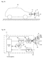
- FIGS. 1A and 1B show overall configuration diagrams of an in-vehicle radar device according to an embodiment of the present invention.
- an in-vehicle radar device 11 attached on a front side of an own vehicle 10 such as a front grill irradiates the front (advancing direction) of the own vehicle 10 with a laser beam 12 in a pulse form, receives a reflected light 13 (more precisely, receives light, but described as receive for the sake of convenience), and detects an obstacle (hereinafter also referred to as a target) such as leading vehicle existing on the front side of the own vehicle 10 from the reception data and calculates information including a distance to the target (distance from the own vehicle 10), a direction (direction with the advancing direction of the own vehicle 10 as a reference) and target width (width in the horizontal direction of the target), and outputs the information to other systems (e.g., leading vehicle following system etc.) mounted on the own vehicle 10.
- laser is an abbreviation (laser) of light amplification by stimulated emission of radiation, and is generally a coherent light in which the phase of a single wavelength is aligned and is understood as a light ray of beam shape which cross-section is thinly narrowed to a circle.
- the illustrated laser beam 12 complies with this interpretation in being a coherent light, but the shape of the cross-section of the beam does not comply. More specifically, the laser beam 12 differs in having a so-called fan beam shape in which a width ⁇ in a vertical direction is large with respect to a width ⁇ in a horizontal direction.
- the reason for having a fan beam shape is to be less susceptible to the up and down movement (pitching movement) of a vehicle body involved in the traveling of the own vehicle 10. That is, if the width ⁇ in the vertical direction is also narrowed, the laser beam 12 moves up and down with the pitching of the own vehicle 10 and the target cannot be captured, where such a drawback can be avoided by having the width ⁇ in the vertical direction slightly large in view of the pitching.
- the width ⁇ in the horizontal direction of the laser beam 12 determines the target resolution in the horizontal direction of the in-vehicle radar device 11, and thus is desirably as narrow as possible, but the width ⁇ in the horizontal direction that is too narrow leads to increase in a horizontal scanning unit region, to be hereinafter described, and the scanning time of one horizontal scan (angle ⁇ ) becomes long with the increase in the amount of information, and thus the width ⁇ is appropriately set in view of both aspects (target resolution and horizontal scanning time).
- the in-vehicle radar device 11 is configured including a transmission unit 14, a horizontal scanning unit 15, a reception unit 16, a control unit 17, and a storage unit 18.
- the transmission unit 14 pulse modulates the laser beam and outputs to the horizontal scanning unit 15 according to a transmit instruction from the control unit 17.
- An output interval (pulse interval) of the laser beam determines a maximum detection distance of the in-vehicle radar device 11.
- the horizontal scanning unit 15 horizontally scans the laser beam of pulse form from the transmission unit 14 and irradiates the front side of the own vehicle 10 with the laser beam.
- the horizontal scan is sequentially carried out according to a scan instruction from the control unit 17 for every horizontal scanning unit regions 12a to 12d segmentalized from a predetermined horizontal scan angle ⁇ (angle sufficiently covering a monitoring range at the front side of the own vehicle 10, for example, angle of about 30 degrees), where the angle of the respective horizontal scanning unit regions 12a to 12d is ⁇ .
- the horizontal scan of the laser beam by the horizontal scanning unit 15 can be carried out through an optical method such as using a rotatable polygon mirror, but the idea of the present invention is not limited thereto.
- the point is to horizontally scan the laser beam in units of angle ⁇ and in a range of a predetermined angle ⁇ , and thus the range of the predetermined angle ⁇ may be horizontally scanned by arranging a laser light source such as a laser diode in an array form in units of angle ⁇ , and sequentially driving such light sources.
- the illustrated transmission unit 14 and the horizontal scanning unit 15 are not distinguished, and are integrated.
- the control unit 17 includes that configured with a micro-processor unit of program control type (so-called computer) or that in which all or most logical portions are configured by hard logic, but the former configuration (configured by a computer) is adopted below for the sake of convenience, in which case, the control unit 17, through the execution of the control program to be hereinafter described, retrieves reception data of the reception unit 16 and stores the same in the storage unit 18 while controlling the operation of the transmission unit 14 and the horizontal scanning unit 15, detects the target such as the leading vehicle existing in front of the own vehicle 10 based on the reception data, calculates information including the distance and the direction to the target, as well as the target width from the distance and the direction, and outputs the information to other systems (e.g., inter-vehicle distance control system etc.) mounted on the own vehicle 10.
- other systems e.g., inter-vehicle distance control system etc.
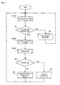
- FIG. 2 shows a diagram showing a simple operation flow of the control program executed by the control unit 17.
- the reception data is first acquired while sequentially scanning the range of one horizontal scanning angle ⁇ by every horizontal scanning unit regions 12a to 12d (step S100).
- step S100 The specific description of the horizontal scanning process will be hereinafter described.
- step S1 judgment is then made whether or not effective reception data is included in the reception data acquired in such a horizontal scanning period (step S1), and a reception data table 19 (see FIG. 4 ) to be hereinafter described is cleared (step S2) if not included, and the horizontal scanning process is again executed (step S100).
- effective reception data refers to the reception data of a magnitude exceeding a predetermined threshold value set in view of background noise and the like.
- the information (the distance, the direction to target, the target width, and the like) of the target is extracted based on the reception data (step S200).
- the specific description of the information extracting process of the target will be hereinafter described.
- step S300 which is the feature of the present embodiment, is then executed, and thereafter, a flag (transfer flag) that is turned ON when judged as transfer by the transfer judgment process is examined (step S3), where judgment is made that involuntary transfer has not occurred if the flag is turned OFF, and the information of the target extracted in step S200 is output to the other systems (step S4), and then the horizontal scanning process is again executed (step S100), whereas judgment is made that involuntary transfer has occurred if the transfer flag is turned ON, and the transfer flag is turned OFF (step S5), and then the horizontal scanning process is again executed (step S100).
- a flag transfer flag
- FIG. 3 shows a diagram showing a specific operation flow of the horizontal scanning process (step S100 of FIG. 2 ).
- the horizontal scanning unit region 12a is number zero
- the horizontal scanning unit region 12b is number one
- the horizontal scanning unit region 12c is number two
- i 0, and thus the horizontal scanning unit region 12a is scanned.
- reception data during scanning of the horizontal scanning unit region 12a is then saved in a reception data table in the storage unit 18 (step S103).
- FIG. 4 shows a configuration diagram of one example of a reception data table 19.
- the reception data table 19 is configured by numerous records including an i field 19a, a distance field 19b, and a reception level field 19c.
- n is a total number of horizontal scanning unit regions 12a to 12d (number of segmentations of the horizontal scanning angle ⁇ ).
- the distance field 19b of each record is stored with the distance to the target detected from the reception data of the corresponding horizontal scanning unit region, and the reception level field 19c is stored with the intensity of the reception data (reception level: intensity of light received).
- step S104 After saving of the reception data is completed, the variable i is counted up (step S104), and judgment is made whether or not the variable i is the same or greater than the number of segmentations n of the horizontal scanning angle ⁇ (step S105). If the judgment result is negative ("NO"), determination is made as still being in the middle of one horizontal scanning period, and step S102 and thereafter are again executed, whereas if the judgment result is positive (“YES”), determination is made that one horizontal scanning period is completed, and the process proceeds to step S1 of FIG. 2 .
- FIG. 5 shows a diagram showing a specific operation flow of the target information extracting process (step S200 of FIG. 2 ).
- the reception data stored in the reception data table 19 is first grouped (step S201), the distance, the direction, and the width for every group are calculated (step S202), and then the process proceeds to step S300 of FIG. 2 .
- the distance, the direction, and the width for every group are the distance of the target, the direction of the target, and the width of the target, respectively.
- FIGS. 6A and 6B show conceptual diagrams of the grouping of the reception data, and the calculation of the distance, the direction, and the width for every group.
- FIG. 6A has the distance on the vertical axis, and the horizontal scanning angle on the horizontal axis
- FIG. 6B has the reception level on the vertical axis and the horizontal scanning angle on the horizontal axis.
- the equally spaced broken lines on the horizontal axes of FIGS. 6A and 6B show the boundary of respective regions (horizontal scanning unit regions 12a to 12d) in which the horizontal scanning angle ⁇ is segmentalized into n parts.
- the information of the reception data saved in the reception data table 19 of when one horizontal scanning is completed is as shown in FIG. 6A . That is, as one example, four reception data 21 to 24 are saved, the distance of the reception data 21 to 24 is substantially the same value (R), and the regions are densely-packed.
- the reception data 21 to 24 can be assumed as representing one target, and thus the four reception data are set as one group (i.e., target 25).
- the distance of the target 25 is specified as R and the width of the target 25 is specified as L, and furthermore, a center angle T ⁇ of the region having the maximum reception level, for example, of the four reception data 21 to 24 configuring the target 25 is specified as the direction of the target 25, as shown in FIG. 6B .
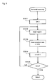
- FIG. 7 shows a diagram showing a specific operation flow of the transfer judgment process (step S300 of FIG. 2 ).
- the intensity (reception level) of the reception data of the horizontal scanning period for this time and the intensity (reception level) of the reception data of the horizontal scanning period of the previous time or the few times before stored in the reception data table 19 of the storage unit 18 are compared to judge whether the reception level is in a suddenly decreasing tendency (step S301) or in a suddenly increasing tendency (step S304), and the process proceeds to step S3 of FIG. 2 if not suddenly decreasing nor suddenly increasing.
- step S302 If in the suddenly decreasing tendency, the enlargement of the width of the target is judged (step S302), where the transfer flag is turned ON (step S303) and then the process proceeds to step S3 of FIG. 2 if enlarging. If the width of the target is not enlarging, the process proceeds to step S3 of FIG. 2 . In the case of suddenly increasing tendency as well, the transfer flag is turned ON (step S305), and then the process proceeds to step S3 of FIG. 2 .
- FIGS. 8A and 8B show explanatory diagrams of the judgment operation in the transfer judgment process.
- a leading vehicle 26 is present in front of the own vehicle 10, as shown in FIG. 8A .
- the leading vehicle 26 is irradiated with laser beams 27 to 38 of each horizontal scanning unit region from the in-vehicle radar device 11 of the own vehicle 10.
- four laser beams 31 to 34 with hatching hit the rear part of the leading vehicle 26, and thus the reflected lights of the four laser beams 31 to 34 are received by the in-vehicle radar device 11 as effective reception data in this case.
- the reception data 31 to 34 correspond to the four reception data 21 to 24 of FIG.
- the distance R to the leading vehicle 26 (correspond to target 25) is obtained from the reception data 31 to 34, and the width L of the leading vehicle 26 is obtained from the angle formed by the region from which the reception data 31 to 34 are obtained. Furthermore, the direction of the leading vehicle 26 is obtained from the position of the data having the maximum reception level of the reception data 31 to 34.
- FIG. 8B The transfer of when the leading vehicle 26 starts to go up a steep hill is shown in FIG. 8B .
- the road surface of an uphill 39 is irradiated with the majority of the laser beams 27 to 38 emitted from the in-vehicle radar device 11 of the own vehicle 10.
- the road surface of the uphill 39 is irradiated with eight laser beams 29 to 36 with hatching. Similar to the above, with the eight laser beams 29 to 36 as the reception data of the in-vehicle radar device 11, the intensity (reception level) of the reception data 29 to 36 is considerably weak compared to the reception data 31 to 34 of FIG. 8A in this case.
- step S301 of FIG. 7 is the condition for distinguishing the difference between the rear part reflection of the leading vehicle 26 and the road surface reflection. According to the experiments of the inventors, the reflection intensity from the road surface was about 10% of the reflection intensity from the vehicle.
- a width La of the rear part reflection of the leading vehicle 26 is smaller than or equal to a maximum width 2.5 m of the vehicle defined in vehicle restriction law (see Law 3(1)(i)) excluding special vehicles, and a normal road surface width Lb is significantly larger than the vehicle maximum width (e.g., about 4 m or 5 m), and thus when the lining width (width Lb) of the reception data 29 to 36 significantly greater than 2.5m is obtained (judged as "YES" in step S302 of FIG. 7 ) as shown in FIG. 8B , judgment is made that wrong target capturing (transfer) from the leading vehicle 26 to the uphill road surface apparently occurred with the above condition (sudden decrease in reception level).
- the in-vehicle radar device 11 of the present embodiment it is possible to reliably avoid the occurrence of wrong target recognition (transfer) that arises when the leading vehicle starts to go up a steep hill or when an obstacle (road sign board etc.) that satisfactorily reflects light is installed in the middle and the leading vehicle starts to go down a steep hill.
- the irradiation angle in the vertical direction of the laser beam 12 is changed to slightly upward when the transfer of when the leading vehicle 26 starts to go up the steep hill is judged.
- the irradiation angle in the vertical direction of the laser beam 12 is changed to slightly downward when the transfer of when the leading vehicle 26 starts to go down the steep hill is judged. Either case is preferable as the leading vehicle 26 can be recaptured.
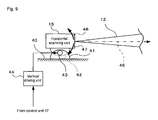
- FIG. 9 shows a configuration diagram of one example of a vertical direction changing mechanism of the laser beam.
- a base 41 is fixed to a horizontal site 40 of a vehicle body (of the own vehicle 10), and the horizontal scanning unit 15 having the emitting surface of the laser beam 12 facing the right is integrally attached on a seat 42 axially supported in a pivotal manner on the base 41.
- An actuator 43 such as a motor is attached to the base 41, which actuator 43 normal rotates or reverse rotates by a required amount according to the polarity and the magnitude of a drive current from a vertical driving unit 44, and the vertical driving unit 44 generates the drive current according to a control command from the control unit 17 (see FIG. 1 ).
- the horizontal scanning unit 15 integral with the seat 42 pivots by the normal rotation or the reverse rotation of the actuator 43, and thus an optical axis 45 of the laser beam 12 changes to upward in the vertical direction as shown by an arrow 46 or downward in the vertical direction as shown by an arrow 47 with such pivoting.
- the vertical direction changing mechanism of the laser beam may be any other than the illustrated type. The point is merely to change the optical axis 45 of the laser beam 12 upward in the vertical direction as shown by the arrow 46 or downward in the vertical direction as shown by the arrow 47 according to the control command from the control unit 17.
- the following may be used for the condition of judging the transfer when the leading vehicle starts to go up a steep hill.
- the following may be used for the condition of judging the transfer when the obstacle (road sign board etc.) that satisfactorily reflects light is installed in the middle and the leading vehicle starts to go down a steep hill.
Abstract

Description
- The present invention relates to an in-vehicle radar device mounted on a vehicle such as automobile (hereinafter referred to as a vehicle).
- An in-vehicle radar device is a radar device of a so-called pulse radar type for emitting electromagnetic waves such as an electric wave and light towards the front side of a vehicle in a bundle (pulse form), and detecting information including a distance and a direction to an obstacle at the front side of an own vehicle based on the reflected wave from the front side of the vehicle. An electric field and a magnetic field include a static field, which is temporally constant, and a wave field which temporally fluctuates and propagates to a distant in space, where the wave field is referred to as a "electromagnetic wave". The typical electromagnetic wave is an electric wave, but light, X-ray and the like are also electromagnetic waves.
- The electromagnetic wave of pulse form emitted from a transmission unit of the in-vehicle radar device is reflected by a body surface (rear reflector or reflecting site corresponding thereto) of an obstacle at front of the own vehicle (hereinafter referred to as a leading vehicle for the sake of convenience), and received by a reception unit of the in-vehicle radar device. Assuming a time from an emission of the electromagnetic wave to a reception of the reflected wave is T, the distance L from the leading vehicle is given by "L = (T x velocity of light) / 2". The direction of the leading vehicle with the own vehicle (vehicle installed with in-vehicle radar device) as a reference is obtained in the emitting direction of the pulse-form electromagnetic wave, and for instance, the direction of the leading vehicle is obtained as 0 degrees if the emitting direction is 0 degrees (i.e., advancing direction of the own vehicle).
- The related art of the in-vehicle radar device as described in Japanese Unexamined Patent Publication No.
2003-42757 - According to the principle described above, the in-vehicle radar device detects the distance and the direction to the obstacle (leading vehicle etc.) in front of the vehicle, but the reflected wave also includes reflected wave from that which should not originally be detected as an obstacle such as road surface, in which case, there is a problem that the road surface may be wrongly detected as false obstacle.
- In the related art, focusing on the difference in the waveform of the reflected wave from the leading vehicle and the reflected wave from the road surface, more specifically, on the fact that the intensity of the reflected wave from the leading vehicle is greater than that of the reflected wave from the road surface and that the duration time (spread of the base of the reflected waveform) of the reflected wave from the leading vehicle is shorter than that of the reflected wave from the road surface, a mechanism for distinguishing them (leading vehicle and road surface) based on such differences is disclosed (see paragraph [0040] and
FIG. 5 of Japanese Unexamined Patent Publication No.2003-42757 - However, in the conventional in-vehicle radar device described in Japanese Unexamined Patent Publication No.
2003-42757 -
FIG. 10 shows an explanatory view (case of the uphill) of the drawback of the related art. In this figure, suppose a leadingvehicle 2 traveling in front of anown vehicle 1 is captured by alaser beam 4 emitted from an in-vehicle radar device 3 of theown vehicle 1, as shown inFIG. 10A . When the leadingvehicle 2 starts to go up a steep hill, as shown inFIG. 10B , thelaser beam 4 emitted from the in-vehicle radar device 3 deviates from the leadingvehicle 2 and irradiates aclimbing road 5. Such climbing road 5 (steep hill) is often seen at the entrance of an indoor parking, climbing entrance of a bank etc., and the like. - Therefore, in this manner, when the
laser beam 4 deviates from the leadingvehicle 2 and irradiates theclimbing road 5, the in-vehicle radar device 3 should essentially judge that the leadingvehicle 2 is lost (lose sight) and quit capturing the target, and carry out the required procedures (e.g., lost alarm etc. to a driver), but theclimbing road 5 is often wrongly recognized as the leadingvehicle 2, and a result, the target capturing (leading 2 → climbing road 5) is continued according to the experiments (using the related art described above) of the inventors of the present invention. - This is a wrong target capturing from the leading
vehicle 2 to theclimbing road 5. This wrong target capturing is hereinafter referred to as "transfer", where when such transfer occurs, wrong judgment is made that the leadingvehicle 2 has suddenly stopped when the measurement result of the in-vehicle radar device 3 is used in an inter-vehicle distance control system, thereby falling into an undesirable situation where sudden braking of theown vehicle 1 is forced. - The cause of such involuntary result is assumed to be because the waveforms of the reflected wave reflected by the hill and the reflected wave from the leading
vehicle 2 are very similar in the case of a steep hill (climbing road 5) of an extent the transfer occurs. - Such a transfer problem also occurs not only in the steep uphill but also in a downhill.
-
FIG. 11 shows an explanatory view (case of the downhill) of the drawback of the related art. In the figure, suppose the leadingvehicle 2 traveling in front of theown vehicle 1 is captured by thelaser beam 4 emitted from the in-vehicle radar device 3 of theown vehicle 1, as shown inFIG. 11A . Assuming a steep downhill is in front of the leadingvehicle 2, a fixed obstacle (typically, road sign board 6) that satisfactorily reflects light is installed in the middle of the downhill, and theroad sign board 6 is positioned on an extended line in the irradiating direction of thelaser beam 4. - When the leading
vehicle 2 starts to go down the steep hill, as shown inFIG. 11B , thelaser beam 4 emitted from the in-vehicle radar device 3 deviates from the leadingvehicle 2 and irradiates theroad sign board 6, and the wrong target capturing (transfer) from the leadingvehicle 2 to theroad sign board 6 occurs, similar toFIG. 10 . Thus, wrong judgment is made that the leadingvehicle 2 has suddenly stopped, thereby falling into an undesirable situation where sudden braking of theown vehicle 1 is forced. The cause thereof is also assumed to be because the waveforms of the reflected wave reflected by the fixed obstacle (road sign board 6) installed in the middle of the hill and the reflected wave from the leadingvehicle 2 are very similar in the case of a steep hill of an extent the transfer occurs. - It is an object of the present invention to provide an in-vehicle radar device capable of avoiding the occurrence of wrong target capturing (transfer).
- In accordance with one aspect of the present invention, the invention according to
claim 1 relates to an in-vehicle radar device including transmission means for emitting an electromagnetic wave; scanning means for horizontally scanning the electromagnetic wave emitted by the transmission means; and reception means for receiving a reflected wave reflected by a target with respect to the electromagnetic wave emitted by the transmission means; the in-vehicle radar device detecting, based on an elapsed time from when the transmission means emitted the electromagnetic wave until the reception means receives the reflected wave and the scanning direction of the electromagnetic wave by the scanning means, at least a position and a horizontal width of the target reflecting the electromagnetic wave; the in-vehicle radar device further including storage means for storing intensity of a previous time or a few times before of the reflected wave received by the reception means; comparing means for comparing the intensity of the reflected wave of the previous time or the few times before stored in the storage means and intensity for this time; and first judgment means for judging that the target detected this time differs from a target continuously detected the from a previous time or a few times before when the intensity of the reflected wave for this time suddenly decreased compared to the intensity of the previous time or the few times before, and the horizontal width of the target becomes greater than a horizontal width of a general vehicle.
The term "sudden decrease" will be defined. Assume two objects having a difference in the reflection efficiency of the electromagnetic wave to be a high reflection object and a low reflection object. It can be said that the body of the vehicle is the "high reflection object" since the surface is well polished and thus satisfactorily reflects the electromagnetic wave, whereas the road surface is the "low reflection object" since the surface is covered with microscopic bumps. "Sudden decrease" refers to change in the intensity of the reflected wave on the time axis when the reflected wave switches to the reflected wave from the low reflection object while receiving the reflected wave from the high reflection object. Therefore, "sudden" in sudden decrease is not quantitatively expressed. It is only required that the "switch" represents a unique change of a distinguishable extent.
In accordance with another aspect of the present invention, the invention according toclaim 2 relates to an in-vehicle radar device including transmission means for emitting an electromagnetic wave; scanning means for horizontally scanning the electromagnetic wave emitted by the transmission means; and reception means for receiving a reflected wave reflected by a target with respect to the electromagnetic wave emitted by the transmission means; the in-vehicle radar device detecting, based on an elapsed time from when the transmission means emitted the electromagnetic wave until the reception means receives the reflected wave and the scanning direction of the electromagnetic wave by the scanning means, at least a position and a horizontal width of the target reflecting the electromagnetic wave; the in-vehicle radar device further including storage means for storing intensity of a previous time or a few times before of the reflected wave received by the reception means; comparing means for comparing the intensity of the reflected wave of the previous time or the few times before stored in the storage means and intensity for this time; and second judgment means for judging that the target detected this time differs from a target continuously detected from the previous time or the few times before when the intensity of the reflected wave for this time suddenly increased compared to the intensity of the previous time or the few times before.
The term "sudden increase" will be defined. An object that satisfactorily reflects the electromagnetic wave than the high reflection object is referred to as a "super high reflection object". An example of such a super high reflection object is a road sign board drawn with characters, figures and the like with paint mixed with glass powder. "Sudden increase" refers to change in the intensity of the reflected wave on the time axis when the reflected wave switches to the reflected wave from the super high reflection object while receiving the reflected wave from the high reflection object (body of vehicle). Therefore, "sudden" in sudden increase is not quantitatively expressed. It is only required that the "switch" represents a unique change of a distinguishable extent.
The invention according toclaim 3 relates to the in-vehicle radar device according toclaim 1, further including changing means for changing an irradiation angle in a vertical direction of the electromagnetic wave upward when a wrong target is judged in the first judgment means.
The invention according toclaim 4 relates to the in-vehicle radar device according toclaim 2, further including changing means for changing an irradiation angle in a vertical direction of the electromagnetic wave downward when a wrong target is judged in the second judgment means. - According to the present invention, judgment is made that the target detected this time is different from the target continuously detected from the previous time or the few times before when the intensity of the reflected wave is suddenly decreased and the horizontal width of the target is greater than the horizontal width of a general vehicle, or judgment is made that the target detected this time differs from the target continuously detected from the previous time or the few times before when the intensity of the reflected wave is suddenly increased, and thus an in-vehicle radar device capable of avoiding occurrence of involuntary "transfer" can be provided.
-
-
FIGS. 1A and 1B show overall configuration diagrams of an in-vehicle radar device according to an embodiment of the present invention; -
FIG. 2 shows a diagram showing a simple operation flow of a control program executed by acontrol unit 17; -
FIG. 3 shows a diagram showing a specific operation flow of a horizontal scanning process (step S100 ofFIG. 2 ); -
FIG. 4 shows a configuration diagram of one example of a reception data table 19; -
FIG. 5 shows a diagram showing a specific operation flow of a target information extracting process (step S200 ofFIG. 2 ); -
FIGS. 6A and 6B show conceptual diagrams of grouping of the reception data, and calculation of distance, direction, and width for every group; -
FIG. 7 shows a diagram showing a specific operation flow of a transfer judgment process (step S300 ofFIG. 2 ); -
FIGS. 8A and 8B show explanatory diagrams of the judgment operation in the transfer judgment process; -
FIG. 9 shows a configuration diagram of one example of a vertical direction changing mechanism of a laser beam; -
FIGS. 10A and 10B show explanatory views (case of an uphill) of the drawbacks of related art; and -
FIGS. 11A and 11B show explanatory views (case of a downhill) of the drawbacks of the related art. - With reference to the drawings, an embodiment of the present invention will be described below using application to the in-vehicle radar device using laser beam by way of example. The specification and actual examples of various details, or illustration of numerical values, character strings, and other symbols in the following description are merely references to clarify the idea of the present invention, and it should be apparent that the idea of the present invention is not limited by all nor one part thereof. The description on the details of the well-known methods, the well-known procedures, the well-known architectures, and the well-known circuit configurations (hereinafter "well-known matters") will be avoided, but this is to simplify the description, and does not intentionally exclude all or one part of the well-known matters. Such well-known matters are known by those skilled in the art at the time of filing of the present invention, and thus are obviously included in the following description.
-
FIGS. 1A and 1B show overall configuration diagrams of an in-vehicle radar device according to an embodiment of the present invention. In the figure, an in-vehicle radar device 11 attached on a front side of anown vehicle 10 such as a front grill irradiates the front (advancing direction) of theown vehicle 10 with alaser beam 12 in a pulse form, receives a reflected light 13 (more precisely, receives light, but described as receive for the sake of convenience), and detects an obstacle (hereinafter also referred to as a target) such as leading vehicle existing on the front side of theown vehicle 10 from the reception data and calculates information including a distance to the target (distance from the own vehicle 10), a direction (direction with the advancing direction of theown vehicle 10 as a reference) and target width (width in the horizontal direction of the target), and outputs the information to other systems (e.g., leading vehicle following system etc.) mounted on theown vehicle 10. - Here, "laser" is an abbreviation (laser) of light amplification by stimulated emission of radiation, and is generally a coherent light in which the phase of a single wavelength is aligned and is understood as a light ray of beam shape which cross-section is thinly narrowed to a circle. The illustrated
laser beam 12 complies with this interpretation in being a coherent light, but the shape of the cross-section of the beam does not comply. More specifically, thelaser beam 12 differs in having a so-called fan beam shape in which a width α in a vertical direction is large with respect to a width β in a horizontal direction. - The reason for having a fan beam shape is to be less susceptible to the up and down movement (pitching movement) of a vehicle body involved in the traveling of the
own vehicle 10. That is, if the width α in the vertical direction is also narrowed, thelaser beam 12 moves up and down with the pitching of theown vehicle 10 and the target cannot be captured, where such a drawback can be avoided by having the width α in the vertical direction slightly large in view of the pitching. - The width β in the horizontal direction of the
laser beam 12 determines the target resolution in the horizontal direction of the in-vehicle radar device 11, and thus is desirably as narrow as possible, but the width β in the horizontal direction that is too narrow leads to increase in a horizontal scanning unit region, to be hereinafter described, and the scanning time of one horizontal scan (angle Σβ) becomes long with the increase in the amount of information, and thus the width β is appropriately set in view of both aspects (target resolution and horizontal scanning time). - Briefly describing, the in-
vehicle radar device 11 is configured including atransmission unit 14, ahorizontal scanning unit 15, areception unit 16, acontrol unit 17, and astorage unit 18. - The
transmission unit 14 pulse modulates the laser beam and outputs to thehorizontal scanning unit 15 according to a transmit instruction from thecontrol unit 17. An output interval (pulse interval) of the laser beam determines a maximum detection distance of the in-vehicle radar device 11. Thehorizontal scanning unit 15 horizontally scans the laser beam of pulse form from thetransmission unit 14 and irradiates the front side of theown vehicle 10 with the laser beam. The horizontal scan is sequentially carried out according to a scan instruction from thecontrol unit 17 for every horizontalscanning unit regions 12a to 12d segmentalized from a predetermined horizontal scan angle Σβ (angle sufficiently covering a monitoring range at the front side of theown vehicle 10, for example, angle of about 30 degrees), where the angle of the respective horizontalscanning unit regions 12a to 12d is β. - Note that the horizontal scan of the laser beam by the
horizontal scanning unit 15 can be carried out through an optical method such as using a rotatable polygon mirror, but the idea of the present invention is not limited thereto. The point is to horizontally scan the laser beam in units of angle β and in a range of a predetermined angle Σβ, and thus the range of the predetermined angle Σβ may be horizontally scanned by arranging a laser light source such as a laser diode in an array form in units of angle β, and sequentially driving such light sources. In this case, the illustratedtransmission unit 14 and thehorizontal scanning unit 15 are not distinguished, and are integrated. - The
control unit 17 includes that configured with a micro-processor unit of program control type (so-called computer) or that in which all or most logical portions are configured by hard logic, but the former configuration (configured by a computer) is adopted below for the sake of convenience, in which case, thecontrol unit 17, through the execution of the control program to be hereinafter described, retrieves reception data of thereception unit 16 and stores the same in thestorage unit 18 while controlling the operation of thetransmission unit 14 and thehorizontal scanning unit 15, detects the target such as the leading vehicle existing in front of theown vehicle 10 based on the reception data, calculates information including the distance and the direction to the target, as well as the target width from the distance and the direction, and outputs the information to other systems (e.g., inter-vehicle distance control system etc.) mounted on theown vehicle 10. -
FIG. 2 shows a diagram showing a simple operation flow of the control program executed by thecontrol unit 17. In the control program, the reception data is first acquired while sequentially scanning the range of one horizontal scanning angle Σβ by every horizontalscanning unit regions 12a to 12d (step S100). The specific description of the horizontal scanning process will be hereinafter described. - After one horizontal scanning process of the angle Σβ is completed, judgment is then made whether or not effective reception data is included in the reception data acquired in such a horizontal scanning period (step S1), and a reception data table 19 (see
FIG. 4 ) to be hereinafter described is cleared (step S2) if not included, and the horizontal scanning process is again executed (step S100). Here, "effective reception data" refers to the reception data of a magnitude exceeding a predetermined threshold value set in view of background noise and the like. - If judged that the effective reception data is present, the information (the distance, the direction to target, the target width, and the like) of the target is extracted based on the reception data (step S200). The specific description of the information extracting process of the target will be hereinafter described.
- The "transfer judgment process" (step S300), which is the feature of the present embodiment, is then executed, and thereafter, a flag (transfer flag) that is turned ON when judged as transfer by the transfer judgment process is examined (step S3), where judgment is made that involuntary transfer has not occurred if the flag is turned OFF, and the information of the target extracted in step S200 is output to the other systems (step S4), and then the horizontal scanning process is again executed (step S100), whereas judgment is made that involuntary transfer has occurred if the transfer flag is turned ON, and the transfer flag is turned OFF (step S5), and then the horizontal scanning process is again executed (step S100).
-
FIG. 3 shows a diagram showing a specific operation flow of the horizontal scanning process (step S100 ofFIG. 2 ). In this flow, a variable i for specifying the horizontalscanning unit regions 12a to 12d is first initialized (i = 0 (step S101), and then the ith horizontal scanning unit region is scanned (step S102). Assuming the horizontalscanning unit region 12a is number zero, the horizontalscanning unit region 12b is number one, the horizontalscanning unit region 12c is number two, ..., and the horizontal scanning unit region 12d is number n. Currently, i = 0, and thus the horizontalscanning unit region 12a is scanned. - The reception data during scanning of the horizontal
scanning unit region 12a is then saved in a reception data table in the storage unit 18 (step S103). -
FIG. 4 shows a configuration diagram of one example of a reception data table 19. In the figure, the reception data table 19 is configured by numerous records including ani field 19a, adistance field 19b, and areception level field 19c. The first record is a reception data saving record of i = 0 (i.e., horizontalscanning unit region 12a), the second record from the first is the reception data saving record of i = 1 (i.e., horizontalscanning unit region 12b), the third record from the first is the reception data saving record of i = 2 (i.e., horizontalscanning unit region 12c), ..., and the last record is the reception data saving record of i = n (i.e., horizontal scanning unit region 12d). Here, n is a total number of horizontalscanning unit regions 12a to 12d (number of segmentations of the horizontal scanning angle Σβ). - The
distance field 19b of each record is stored with the distance to the target detected from the reception data of the corresponding horizontal scanning unit region, and thereception level field 19c is stored with the intensity of the reception data (reception level: intensity of light received). - After saving of the reception data is completed, the variable i is counted up (step S104), and judgment is made whether or not the variable i is the same or greater than the number of segmentations n of the horizontal scanning angle Σβ (step S105). If the judgment result is negative ("NO"), determination is made as still being in the middle of one horizontal scanning period, and step S102 and thereafter are again executed, whereas if the judgment result is positive ("YES"), determination is made that one horizontal scanning period is completed, and the process proceeds to step S1 of
FIG. 2 . -
FIG. 5 shows a diagram showing a specific operation flow of the target information extracting process (step S200 ofFIG. 2 ). In this flow, the reception data stored in the reception data table 19 is first grouped (step S201), the distance, the direction, and the width for every group are calculated (step S202), and then the process proceeds to step S300 ofFIG. 2 . The distance, the direction, and the width for every group are the distance of the target, the direction of the target, and the width of the target, respectively. -
FIGS. 6A and 6B show conceptual diagrams of the grouping of the reception data, and the calculation of the distance, the direction, and the width for every group. In the figure,FIG. 6A has the distance on the vertical axis, and the horizontal scanning angle on the horizontal axis, andFIG. 6B has the reception level on the vertical axis and the horizontal scanning angle on the horizontal axis. The equally spaced broken lines on the horizontal axes ofFIGS. 6A and 6B show the boundary of respective regions (horizontalscanning unit regions 12a to 12d) in which the horizontal scanning angle Σβ is segmentalized into n parts. - Suppose the information of the reception data saved in the reception data table 19 of when one horizontal scanning is completed is as shown in
FIG. 6A . That is, as one example, fourreception data 21 to 24 are saved, the distance of thereception data 21 to 24 is substantially the same value (R), and the regions are densely-packed. In this case, thereception data 21 to 24 can be assumed as representing one target, and thus the four reception data are set as one group (i.e., target 25). The distance of thetarget 25 is specified as R and the width of thetarget 25 is specified as L, and furthermore, a center angle Tβ of the region having the maximum reception level, for example, of the fourreception data 21 to 24 configuring thetarget 25 is specified as the direction of thetarget 25, as shown inFIG. 6B . -
FIG. 7 shows a diagram showing a specific operation flow of the transfer judgment process (step S300 ofFIG. 2 ). In this flow, the intensity (reception level) of the reception data of the horizontal scanning period for this time and the intensity (reception level) of the reception data of the horizontal scanning period of the previous time or the few times before stored in the reception data table 19 of thestorage unit 18 are compared to judge whether the reception level is in a suddenly decreasing tendency (step S301) or in a suddenly increasing tendency (step S304), and the process proceeds to step S3 ofFIG. 2 if not suddenly decreasing nor suddenly increasing. - If in the suddenly decreasing tendency, the enlargement of the width of the target is judged (step S302), where the transfer flag is turned ON (step S303) and then the process proceeds to step S3 of
FIG. 2 if enlarging. If the width of the target is not enlarging, the process proceeds to step S3 ofFIG. 2 .
In the case of suddenly increasing tendency as well, the transfer flag is turned ON (step S305), and then the process proceeds to step S3 ofFIG. 2 . -
FIGS. 8A and 8B show explanatory diagrams of the judgment operation in the transfer judgment process. First, assume a case where a leadingvehicle 26 is present in front of theown vehicle 10, as shown inFIG. 8A . Further, assume the leadingvehicle 26 is irradiated withlaser beams 27 to 38 of each horizontal scanning unit region from the in-vehicle radar device 11 of theown vehicle 10. In the illustrated example, fourlaser beams 31 to 34 with hatching hit the rear part of the leadingvehicle 26, and thus the reflected lights of the fourlaser beams 31 to 34 are received by the in-vehicle radar device 11 as effective reception data in this case. With thelaser beams 31 to 34 with hatching as the reception data below, thereception data 31 to 34 correspond to the fourreception data 21 to 24 ofFIG. 6 . Therefore, the distance R to the leading vehicle 26 (correspond to target 25) is obtained from thereception data 31 to 34, and the width L of the leadingvehicle 26 is obtained from the angle formed by the region from which thereception data 31 to 34 are obtained. Furthermore, the direction of the leadingvehicle 26 is obtained from the position of the data having the maximum reception level of thereception data 31 to 34. - The transfer of when the leading
vehicle 26 starts to go up a steep hill is shown inFIG. 8B . In this case, the road surface of an uphill 39 is irradiated with the majority of thelaser beams 27 to 38 emitted from the in-vehicle radar device 11 of theown vehicle 10. In the illustrated example, the road surface of the uphill 39 is irradiated with eightlaser beams 29 to 36 with hatching. Similar to the above, with the eightlaser beams 29 to 36 as the reception data of the in-vehicle radar device 11, the intensity (reception level) of thereception data 29 to 36 is considerably weak compared to thereception data 31 to 34 ofFIG. 8A in this case. This is because a portion that satisfactorily reflects light such as a number plate is arranged at the rear part of the leadingvehicle 26, whereas such a portion does not exist on the road surface, and the light scatters by the microscopic bumps of the paved surface. The judgment condition (sudden decrease in reception level) of step S301 ofFIG. 7 is the condition for distinguishing the difference between the rear part reflection of the leadingvehicle 26 and the road surface reflection. According to the experiments of the inventors, the reflection intensity from the road surface was about 10% of the reflection intensity from the vehicle. - The difference between the rear part reflection of the leading
vehicle 26 and the road surface reflection is not only the above condition (sudden decrease in reception level) but also appears in the width. In other words, a width La of the rear part reflection of the leadingvehicle 26 is smaller than or equal to a maximum width 2.5 m of the vehicle defined in vehicle restriction law (see Law 3(1)(i)) excluding special vehicles, and a normal road surface width Lb is significantly larger than the vehicle maximum width (e.g., about 4 m or 5 m), and thus when the lining width (width Lb) of thereception data 29 to 36 significantly greater than 2.5m is obtained (judged as "YES" in step S302 ofFIG. 7 ) as shown inFIG. 8B , judgment is made that wrong target capturing (transfer) from the leadingvehicle 26 to the uphill road surface apparently occurred with the above condition (sudden decrease in reception level). - Even the transfer of when an obstacle (
road sign board 6 ofFIG. 11 etc.) that satisfactorily reflects light exists on a traffic lane in the middle of the downhill when the leadingvehicle 26 starts to go down a steep downhill can also be judged, in principle, by the judgment condition (sudden increase in reception level) of step S304 ofFIG. 7 . This is because theroad sign board 6 is drawn with characters and the like using paint mixed with glass powder, and thus the light is satisfactorily reflected by such glass powder (intensity of the reception data suddenly increases). According to the experiments of the inventors, the reflection intensity from the board was about twice the reflection intensity from the vehicle. Therefore, even in a case where the above condition (sudden increase in reception level) is satisfied, judgment is made that the wrong target capturing (transfer) from the leadingvehicle 26 to theroad sign board 6 apparently occurred. - As described above, according to the in-
vehicle radar device 11 of the present embodiment, it is possible to reliably avoid the occurrence of wrong target recognition (transfer) that arises when the leading vehicle starts to go up a steep hill or when an obstacle (road sign board etc.) that satisfactorily reflects light is installed in the middle and the leading vehicle starts to go down a steep hill. - It should be recognized that the idea of the present invention is not limited to the above description, and various development examples and variants are encompassed within the scope of the idea, and the following may be adopted.
- The irradiation angle in the vertical direction of the
laser beam 12 is changed to slightly upward when the transfer of when the leadingvehicle 26 starts to go up the steep hill is judged. The irradiation angle in the vertical direction of thelaser beam 12 is changed to slightly downward when the transfer of when the leadingvehicle 26 starts to go down the steep hill is judged. Either case is preferable as the leadingvehicle 26 can be recaptured. -
FIG. 9 shows a configuration diagram of one example of a vertical direction changing mechanism of the laser beam. In the figure, abase 41 is fixed to ahorizontal site 40 of a vehicle body (of the own vehicle 10), and thehorizontal scanning unit 15 having the emitting surface of thelaser beam 12 facing the right is integrally attached on aseat 42 axially supported in a pivotal manner on thebase 41. An actuator 43 such as a motor is attached to thebase 41, which actuator 43 normal rotates or reverse rotates by a required amount according to the polarity and the magnitude of a drive current from avertical driving unit 44, and thevertical driving unit 44 generates the drive current according to a control command from the control unit 17 (seeFIG. 1 ). According to such a configuration, thehorizontal scanning unit 15 integral with theseat 42 pivots by the normal rotation or the reverse rotation of theactuator 43, and thus anoptical axis 45 of thelaser beam 12 changes to upward in the vertical direction as shown by anarrow 46 or downward in the vertical direction as shown by anarrow 47 with such pivoting. It goes without saying that the vertical direction changing mechanism of the laser beam may be any other than the illustrated type. The point is merely to change theoptical axis 45 of thelaser beam 12 upward in the vertical direction as shown by thearrow 46 or downward in the vertical direction as shown by thearrow 47 according to the control command from thecontrol unit 17. - The following may be used for the condition of judging the transfer when the leading vehicle starts to go up a steep hill.
- Condition 1: Reception level for this time is decreased by a predetermined percentage in comparison with the reception level of the previous time or the few times before.
- Condition 2: Reception data is the data of the target being captured.
- Condition 3: Reception data is the data of the target in close range. The close range refers to a close distance of an extent the own vehicle may hit the target when the target suddenly stops.
- Condition 4: Target is spread over the entire horizontal field (horizontal scanning range) of the in-vehicle radar device.
- Condition 5: Width of the target corresponds to a general road surface width and such width is significantly larger than the width of a general vehicle.
- The following may be used for the condition of judging the transfer when the obstacle (road sign board etc.) that satisfactorily reflects light is installed in the middle and the leading vehicle starts to go down a steep hill.
- Condition 1: Reception level for this time is increased by a predetermined times in comparison with the reception level of the previous time or the few times before.
- Condition 2: Reception data is the data of the target being captured.
- Condition 3: Reception data is the data of the target in intermediate/long range. The intermediate/long range refers to a sufficient distance of an extent the laser beam emitted from the in-vehicle radar device reaches the obstacle (road sign board etc.) installed in the middle of the steep hill that satisfactorily reflects light.
- The above description is for application to the in-vehicle radar device using laser beam, but is not limited thereto, and application may be made to an in-vehicle radar device using other electromagnetic wave medium such as an electric wave.
Claims (4)
- An in-vehicle radar device (11) characterized by comprising:transmission means (14) for emitting an electromagnetic wave (12);scanning means (15) for horizontally scanning the electromagnetic wave (12) emitted by the transmission means (14); andreception means (16) for receiving a reflected wave (13) reflected by a target with respect to the electromagnetic wave (12) emitted by the transmission means (14);the in-vehicle radar device (11) detecting, based on an elapsed time from when the transmission means (14) emitted the electromagnetic wave (12) until the reception means (16) receives the reflected wave (13) and the scanning direction of the electromagnetic wave (12) by the scanning means (15), at least a position and a horizontal width of the target reflecting the electromagnetic wave (12); the in-vehicle radar device (11) further comprising:storage means (18) for storing intensity of a previous time or a few times before of the reflected wave (13) received by the reception means (16);comparing means (17) for comparing the intensity of the reflected wave (13) of the previous time or the few times before stored in the storage means (18) and intensity for this time; andfirst judgment means (17) for judging that the target detected this time differs from a target continuously detected the from the previous time or the few times before if the intensity of the reflected wave (13) for this time suddenly decreased compared to the intensity of the previous time or the few times before, and the horizontal width of the target becomes greater than a horizontal width of a general vehicle.
- An in-vehicle radar device (11) characterized by comprising:transmission means (14) for emitting an electromagnetic wave (12);scanning means (15) for horizontally scanning the electromagnetic wave (12) emitted by the transmission means (14); andreception means (16) for receiving a reflected wave (13) reflected by a target with respect to the electromagnetic wave (12) emitted by the transmission means (14);the in-vehicle radar device (11) detecting, based on an elapsed time from when the transmission means (14) emitted the electromagnetic wave (12) until the reception means (16) receives the reflected wave (13) and the scanning direction of the electromagnetic wave (12) by the scanning means (15), at least a position and a horizontal width of the target reflecting the electromagnetic wave (12); the in-vehicle radar device (11) further comprising:storage means (18) for storing intensity of a previous time or a few times before of the reflected wave (13) received by the reception means (16);comparing means (17) for comparing the intensity of the reflected wave (13) of the previous time or the few times before stored in the storage means (18) and intensity for this time; andsecond judgment means (17) for judging that the target detected this time differs from a target continuously detected from the previous time or the few times before if the intensity of the reflected wave (13) for this time suddenly increased compared to the intensity of the previous time or the few times before.
- An in-vehicle radar device (11) according to claim 1, characterized by further comprising changing means (43) for changing an irradiation angle in a vertical direction of the electromagnetic wave (12) upward when a wrong target is judged in the first judgment means (17).
- An in-vehicle radar device (11) according to claim 2, characterized by further comprising changing means (43) for changing an irradiation angle in a vertical direction of the electromagnetic wave (12) downward when a wrong target is judged in the second judgment means (17).
Applications Claiming Priority (1)
| Application Number | Priority Date | Filing Date | Title |
|---|---|---|---|
| JP2007289217A JP5152840B2 (en) | 2007-11-07 | 2007-11-07 | Automotive radar equipment |
Publications (3)
| Publication Number | Publication Date |
|---|---|
| EP2058678A2 true EP2058678A2 (en) | 2009-05-13 |
| EP2058678A3 EP2058678A3 (en) | 2009-07-22 |
| EP2058678B1 EP2058678B1 (en) | 2016-09-21 |
Family
ID=40348005
Family Applications (1)
| Application Number | Title | Priority Date | Filing Date |
|---|---|---|---|
| EP08167755.1A Not-in-force EP2058678B1 (en) | 2007-11-07 | 2008-10-28 | In-vehicle radar device |
Country Status (5)
| Country | Link |
|---|---|
| US (1) | US7605746B2 (en) |
| EP (1) | EP2058678B1 (en) |
| JP (1) | JP5152840B2 (en) |
| KR (1) | KR101000229B1 (en) |
| CN (1) | CN101430382B (en) |
Cited By (4)
| Publication number | Priority date | Publication date | Assignee | Title |
|---|---|---|---|---|
| EP3767337A4 (en) * | 2018-03-16 | 2021-11-17 | Mitsui E&S Machinery Co., Ltd. | Obstacle sensing system and obstacle sensing method |
| US20220017100A1 (en) * | 2020-07-20 | 2022-01-20 | Hyundai Mobis Co., Ltd. | Radar device for vehicle and method of controlling radar for vehicle |
| DE112018007135B4 (en) | 2018-03-26 | 2022-02-17 | Mitsubishi Electric Corporation | OBJECT RECOGNITION DEVICE, VEHICLE, OBJECT RECOGNITION METHOD AND OBJECT RECOGNITION PROGRAM |
| DE102011007133B4 (en) | 2010-04-09 | 2023-09-07 | Denso Corporation | DEVICE AND METHOD FOR DETECTING THE PRESENCE OF OBJECTS |
Families Citing this family (24)
| Publication number | Priority date | Publication date | Assignee | Title |
|---|---|---|---|---|
| JP4304517B2 (en) * | 2005-11-09 | 2009-07-29 | トヨタ自動車株式会社 | Object detection device |
| JP2009042181A (en) * | 2007-08-10 | 2009-02-26 | Denso Corp | Estimating apparatus |
| JP5152840B2 (en) * | 2007-11-07 | 2013-02-27 | オムロンオートモーティブエレクトロニクス株式会社 | Automotive radar equipment |
| KR101137088B1 (en) * | 2010-01-06 | 2012-04-19 | 주식회사 만도 | Integrated Radar Apparatus and Integrated Antenna Apparatus |
| JP5743661B2 (en) * | 2011-04-08 | 2015-07-01 | 本田技研工業株式会社 | Vehicle object detection device |
| JP5658087B2 (en) * | 2011-05-19 | 2015-01-21 | 本田技研工業株式会社 | Object detection device |
| CN102393516B (en) * | 2011-08-23 | 2013-05-29 | 中国人民解放军军事交通学院 | Swinging device with three-dimensional scanning laser radar |
| JP6369035B2 (en) | 2013-02-05 | 2018-08-08 | 株式会社デンソー | Target detection device |
| KR101808885B1 (en) | 2013-05-16 | 2018-01-19 | 주식회사 만도 | Radar device, obstacle detecting method thereof and vehicle control system using it |
| DE102013215117A1 (en) * | 2013-08-01 | 2015-02-05 | Robert Bosch Gmbh | Object determination by means of radar sensor |
| KR102173994B1 (en) * | 2014-03-18 | 2020-11-04 | 주식회사 만도 | Tuning method and control device of vehicle radar |
| JP6365140B2 (en) | 2014-09-04 | 2018-08-01 | 株式会社Soken | In-vehicle device, in-vehicle system |
| JP6413957B2 (en) * | 2014-12-26 | 2018-10-31 | 株式会社デンソー | Pitching judgment device |
| JP6576254B2 (en) * | 2016-01-25 | 2019-09-18 | オムロンオートモーティブエレクトロニクス株式会社 | Optical radar device |
| CN105911553B (en) * | 2016-04-15 | 2019-01-01 | 北京信息科技大学 | A kind of road feasible zone determines method and system |
| DE102016207463A1 (en) * | 2016-04-29 | 2017-11-02 | Robert Bosch Gmbh | Method and device for operating at least one vehicle with respect to at least one passable object in the vicinity of the at least one vehicle |
| JP6701983B2 (en) * | 2016-06-02 | 2020-05-27 | 株式会社デンソー | Target detection device |
| EP3508873A4 (en) * | 2016-08-31 | 2020-04-15 | Pioneer Corporation | Measuring device, control device, control method, and program |
| WO2018079921A1 (en) * | 2016-10-25 | 2018-05-03 | 전자부품연구원 | Light transmitting and receiving device and method |
| KR102578824B1 (en) | 2016-11-30 | 2023-09-15 | 삼성전자주식회사 | Vehicle radar apparatus providing 3-dimensional information |
| CN107512271A (en) * | 2017-08-15 | 2017-12-26 | 广州智网联运物流有限公司 | Shuttle machine automatic ride control system and its control method |
| CN109849902A (en) * | 2017-11-30 | 2019-06-07 | 博世汽车部件(苏州)有限公司 | Method and apparatus for preventing automobile crash |
| WO2019244334A1 (en) * | 2018-06-22 | 2019-12-26 | 三菱電機株式会社 | Sensor control device, vehicle, sensing method and sensor control program |
| US11378652B2 (en) * | 2019-09-03 | 2022-07-05 | GM Global Technology Operations LLC | Enhancement of vehicle radar system robustness based on elevation information |
Citations (2)
| Publication number | Priority date | Publication date | Assignee | Title |
|---|---|---|---|---|
| JP2003042757A (en) | 2001-07-31 | 2003-02-13 | Omron Corp | Distance measuring instrument for vehicle |
| EP1731924A1 (en) | 2005-06-06 | 2006-12-13 | Omron Corporation | Distance measuring device for a vehicle |
Family Cites Families (22)
| Publication number | Priority date | Publication date | Assignee | Title |
|---|---|---|---|---|
| JPH0735862A (en) * | 1993-07-20 | 1995-02-07 | Komatsu Ltd | Obstacle detector for vehicle |
| JP3125496B2 (en) * | 1993-01-12 | 2001-01-15 | トヨタ自動車株式会社 | Travel control device for vehicles |
| US5784023A (en) * | 1995-06-26 | 1998-07-21 | Bluege; John | Speed detection method |
| EP0773452B1 (en) * | 1995-11-10 | 2000-12-20 | Toyota Jidosha Kabushiki Kaisha | Radar apparatus for detecting a direction of a center of a target |
| JPH10300854A (en) * | 1997-04-22 | 1998-11-13 | Yazaki Corp | Laser radar device to be mounted on vehicle |
| JP3684776B2 (en) * | 1997-07-23 | 2005-08-17 | 株式会社デンソー | Obstacle recognition device for vehicles |
| US6002983A (en) * | 1997-08-27 | 1999-12-14 | Delphi Technologies, Inc. | Angle extent estimation method for a motor vehicle object detection system |
| SE511061C2 (en) * | 1997-11-21 | 1999-07-26 | Celsiustech Electronics Ab | Procedure for classifying raised objects |
| JP3480486B2 (en) * | 1998-08-18 | 2003-12-22 | トヨタ自動車株式会社 | FM-CW radar device |
| JP3577239B2 (en) * | 1999-05-28 | 2004-10-13 | 三菱電機株式会社 | Radar equipment |
| JP3915742B2 (en) * | 2003-06-20 | 2007-05-16 | 株式会社デンソー | Vehicle object recognition device |
| JP3994941B2 (en) * | 2003-07-22 | 2007-10-24 | オムロン株式会社 | Radar equipment for vehicles |
| JP2005233716A (en) * | 2004-02-18 | 2005-09-02 | Omron Corp | Radar device |
| JP2005291788A (en) * | 2004-03-31 | 2005-10-20 | Denso Corp | Object recognition device for vehicle |
| JP4429102B2 (en) * | 2004-07-20 | 2010-03-10 | 三菱電機株式会社 | Radar apparatus and radar signal processing method |
| DE102004059915A1 (en) * | 2004-12-13 | 2006-06-14 | Robert Bosch Gmbh | radar system |
| JP2006258497A (en) * | 2005-03-15 | 2006-09-28 | Omron Corp | Object recognition apparatus for vehicle |
| WO2006134912A1 (en) * | 2005-06-17 | 2006-12-21 | Murata Manufacturing Co., Ltd. | Radar apparatus |
| JP4890892B2 (en) * | 2006-03-10 | 2012-03-07 | オムロンオートモーティブエレクトロニクス株式会社 | Ranging device for vehicles |
| JP4899599B2 (en) * | 2006-04-07 | 2012-03-21 | マツダ株式会社 | Vehicle obstacle detection device |
| JP2008232887A (en) * | 2007-03-22 | 2008-10-02 | Omron Corp | Object sensing apparatus and irradiation axis adjustment method |
| JP5152840B2 (en) * | 2007-11-07 | 2013-02-27 | オムロンオートモーティブエレクトロニクス株式会社 | Automotive radar equipment |
-
2007
- 2007-11-07 JP JP2007289217A patent/JP5152840B2/en not_active Expired - Fee Related
-
2008
- 2008-10-28 EP EP08167755.1A patent/EP2058678B1/en not_active Not-in-force
- 2008-11-06 KR KR1020080109762A patent/KR101000229B1/en active IP Right Grant
- 2008-11-06 US US12/266,381 patent/US7605746B2/en not_active Expired - Fee Related
- 2008-11-06 CN CN2008101731988A patent/CN101430382B/en not_active Expired - Fee Related
Patent Citations (2)
| Publication number | Priority date | Publication date | Assignee | Title |
|---|---|---|---|---|
| JP2003042757A (en) | 2001-07-31 | 2003-02-13 | Omron Corp | Distance measuring instrument for vehicle |
| EP1731924A1 (en) | 2005-06-06 | 2006-12-13 | Omron Corporation | Distance measuring device for a vehicle |
Cited By (6)
| Publication number | Priority date | Publication date | Assignee | Title |
|---|---|---|---|---|
| DE102011007133B4 (en) | 2010-04-09 | 2023-09-07 | Denso Corporation | DEVICE AND METHOD FOR DETECTING THE PRESENCE OF OBJECTS |
| EP3767337A4 (en) * | 2018-03-16 | 2021-11-17 | Mitsui E&S Machinery Co., Ltd. | Obstacle sensing system and obstacle sensing method |
| DE112018007135B4 (en) | 2018-03-26 | 2022-02-17 | Mitsubishi Electric Corporation | OBJECT RECOGNITION DEVICE, VEHICLE, OBJECT RECOGNITION METHOD AND OBJECT RECOGNITION PROGRAM |
| US11609307B2 (en) | 2018-03-26 | 2023-03-21 | Mitsubishi Electric Corporation | Object detection apparatus, vehicle, object detection method, and computer readable medium |
| US20220017100A1 (en) * | 2020-07-20 | 2022-01-20 | Hyundai Mobis Co., Ltd. | Radar device for vehicle and method of controlling radar for vehicle |
| US11858518B2 (en) * | 2020-07-20 | 2024-01-02 | Hyundai Mobis Co., Ltd. | Radar device for vehicle and method of controlling radar for vehicle |
Also Published As
| Publication number | Publication date |
|---|---|
| US7605746B2 (en) | 2009-10-20 |
| KR101000229B1 (en) | 2010-12-10 |
| EP2058678A3 (en) | 2009-07-22 |
| EP2058678B1 (en) | 2016-09-21 |
| CN101430382A (en) | 2009-05-13 |
| JP5152840B2 (en) | 2013-02-27 |
| US20090135047A1 (en) | 2009-05-28 |
| JP2009115628A (en) | 2009-05-28 |
| KR20090047369A (en) | 2009-05-12 |
| CN101430382B (en) | 2011-11-30 |
Similar Documents
| Publication | Publication Date | Title |
|---|---|---|
| EP2058678B1 (en) | In-vehicle radar device | |
| US7650239B2 (en) | Object recognition apparatus for motor vehicle | |
| JP5267592B2 (en) | Object recognition device | |
| JP3405327B2 (en) | Object recognition method and apparatus, recording medium | |
| US20050219506A1 (en) | Object recognition device for vehicle | |
| US7260465B2 (en) | Ramp identification in adaptive cruise control | |
| JP3639190B2 (en) | Object recognition device, recording medium | |
| JP3772969B2 (en) | Automotive radar equipment | |
| EP2784542A1 (en) | Laser radar device | |
| CN112440984B (en) | vehicle control system | |
| US7468791B2 (en) | Object recognition system for vehicle | |
| JP2005043201A (en) | Radar device for vehicle | |
| EP2784541A1 (en) | Laser radar device | |
| JPH1194946A (en) | Obstacle recognition device for vehicle | |
| JP2002257934A (en) | Road surface condition detector for vehicle and range- finder for vehicle | |
| JP2009042177A (en) | Object detecting device | |
| CN112172816A (en) | Lane change control apparatus and method for autonomous vehicle | |
| CN110316187B (en) | Automobile and obstacle avoidance control method thereof | |
| JP4284652B2 (en) | Radar equipment | |
| JP2004184332A (en) | Object recognition apparatus for motor vehicle and apparatus for controlling distance between motor vehicle | |
| JP2004125636A (en) | On-vehicle laser radar device | |
| JPH10151987A (en) | Forward lighting system of vehicle | |
| JPH03111785A (en) | Preceding-vehicle recognizing apparatus | |
| JPH11115623A (en) | Auto-fog lamp device | |
| KR20130061250A (en) | Tracking method of vehicle's surrounding obstacles |
Legal Events
| Date | Code | Title | Description |
|---|---|---|---|
| PUAI | Public reference made under article 153(3) epc to a published international application that has entered the european phase |
Free format text: ORIGINAL CODE: 0009012 |
|
| AK | Designated contracting states |
Kind code of ref document: A2 Designated state(s): AT BE BG CH CY CZ DE DK EE ES FI FR GB GR HR HU IE IS IT LI LT LU LV MC MT NL NO PL PT RO SE SI SK TR |
|
| AX | Request for extension of the european patent |
Extension state: AL BA MK RS |
|
| PUAL | Search report despatched |
Free format text: ORIGINAL CODE: 0009013 |
|
| AK | Designated contracting states |
Kind code of ref document: A3 Designated state(s): AT BE BG CH CY CZ DE DK EE ES FI FR GB GR HR HU IE IS IT LI LT LU LV MC MT NL NO PL PT RO SE SI SK TR |
|
| AX | Request for extension of the european patent |
Extension state: AL BA MK RS |
|
| 17P | Request for examination filed |
Effective date: 20100120 |
|
| 17Q | First examination report despatched |
Effective date: 20100218 |
|
| AKX | Designation fees paid |
Designated state(s): AT BE BG CH CY CZ DE DK EE ES FI FR GB GR HR HU IE IS IT LI LT LU LV MC MT NL NO PL PT RO SE SI SK TR |
|
| RAP1 | Party data changed (applicant data changed or rights of an application transferred) |
Owner name: OMRON AUTOMOTIVE ELECTRONICS CO., LTD. |
|
| GRAP | Despatch of communication of intention to grant a patent |
Free format text: ORIGINAL CODE: EPIDOSNIGR1 |
|
| INTG | Intention to grant announced |
Effective date: 20160401 |
|
| GRAS | Grant fee paid |
Free format text: ORIGINAL CODE: EPIDOSNIGR3 |
|
| GRAA | (expected) grant |
Free format text: ORIGINAL CODE: 0009210 |
|
| AK | Designated contracting states |
Kind code of ref document: B1 Designated state(s): AT BE BG CH CY CZ DE DK EE ES FI FR GB GR HR HU IE IS IT LI LT LU LV MC MT NL NO PL PT RO SE SI SK TR |
|
| REG | Reference to a national code |
Ref country code: GB Ref legal event code: FG4D |
|
| REG | Reference to a national code |
Ref country code: CH Ref legal event code: EP |
|
| REG | Reference to a national code |
Ref country code: AT Ref legal event code: REF Ref document number: 831490 Country of ref document: AT Kind code of ref document: T Effective date: 20161015 |
|
| REG | Reference to a national code |
Ref country code: IE Ref legal event code: FG4D |
|
| REG | Reference to a national code |
Ref country code: DE Ref legal event code: R096 Ref document number: 602008046370 Country of ref document: DE |
|
| REG | Reference to a national code |
Ref country code: LT Ref legal event code: MG4D Ref country code: NL Ref legal event code: MP Effective date: 20160921 |
|
| PG25 | Lapsed in a contracting state [announced via postgrant information from national office to epo] |
Ref country code: NO Free format text: LAPSE BECAUSE OF FAILURE TO SUBMIT A TRANSLATION OF THE DESCRIPTION OR TO PAY THE FEE WITHIN THE PRESCRIBED TIME-LIMIT Effective date: 20161221 Ref country code: LT Free format text: LAPSE BECAUSE OF FAILURE TO SUBMIT A TRANSLATION OF THE DESCRIPTION OR TO PAY THE FEE WITHIN THE PRESCRIBED TIME-LIMIT Effective date: 20160921 Ref country code: FI Free format text: LAPSE BECAUSE OF FAILURE TO SUBMIT A TRANSLATION OF THE DESCRIPTION OR TO PAY THE FEE WITHIN THE PRESCRIBED TIME-LIMIT Effective date: 20160921 |
|
| REG | Reference to a national code |
Ref country code: AT Ref legal event code: MK05 Ref document number: 831490 Country of ref document: AT Kind code of ref document: T Effective date: 20160921 |
|
| PG25 | Lapsed in a contracting state [announced via postgrant information from national office to epo] |
Ref country code: NL Free format text: LAPSE BECAUSE OF FAILURE TO SUBMIT A TRANSLATION OF THE DESCRIPTION OR TO PAY THE FEE WITHIN THE PRESCRIBED TIME-LIMIT Effective date: 20160921 Ref country code: BE Free format text: LAPSE BECAUSE OF NON-PAYMENT OF DUE FEES Effective date: 20161031 Ref country code: SE Free format text: LAPSE BECAUSE OF FAILURE TO SUBMIT A TRANSLATION OF THE DESCRIPTION OR TO PAY THE FEE WITHIN THE PRESCRIBED TIME-LIMIT Effective date: 20160921 Ref country code: GR Free format text: LAPSE BECAUSE OF FAILURE TO SUBMIT A TRANSLATION OF THE DESCRIPTION OR TO PAY THE FEE WITHIN THE PRESCRIBED TIME-LIMIT Effective date: 20161222 Ref country code: LV Free format text: LAPSE BECAUSE OF FAILURE TO SUBMIT A TRANSLATION OF THE DESCRIPTION OR TO PAY THE FEE WITHIN THE PRESCRIBED TIME-LIMIT Effective date: 20160921 |
|
| PG25 | Lapsed in a contracting state [announced via postgrant information from national office to epo] |
Ref country code: RO Free format text: LAPSE BECAUSE OF FAILURE TO SUBMIT A TRANSLATION OF THE DESCRIPTION OR TO PAY THE FEE WITHIN THE PRESCRIBED TIME-LIMIT Effective date: 20160921 Ref country code: EE Free format text: LAPSE BECAUSE OF FAILURE TO SUBMIT A TRANSLATION OF THE DESCRIPTION OR TO PAY THE FEE WITHIN THE PRESCRIBED TIME-LIMIT Effective date: 20160921 |
|
| PG25 | Lapsed in a contracting state [announced via postgrant information from national office to epo] |
Ref country code: AT Free format text: LAPSE BECAUSE OF FAILURE TO SUBMIT A TRANSLATION OF THE DESCRIPTION OR TO PAY THE FEE WITHIN THE PRESCRIBED TIME-LIMIT Effective date: 20160921 Ref country code: ES Free format text: LAPSE BECAUSE OF FAILURE TO SUBMIT A TRANSLATION OF THE DESCRIPTION OR TO PAY THE FEE WITHIN THE PRESCRIBED TIME-LIMIT Effective date: 20160921 Ref country code: BG Free format text: LAPSE BECAUSE OF FAILURE TO SUBMIT A TRANSLATION OF THE DESCRIPTION OR TO PAY THE FEE WITHIN THE PRESCRIBED TIME-LIMIT Effective date: 20161221 Ref country code: CZ Free format text: LAPSE BECAUSE OF FAILURE TO SUBMIT A TRANSLATION OF THE DESCRIPTION OR TO PAY THE FEE WITHIN THE PRESCRIBED TIME-LIMIT Effective date: 20160921 Ref country code: PL Free format text: LAPSE BECAUSE OF FAILURE TO SUBMIT A TRANSLATION OF THE DESCRIPTION OR TO PAY THE FEE WITHIN THE PRESCRIBED TIME-LIMIT Effective date: 20160921 Ref country code: IS Free format text: LAPSE BECAUSE OF FAILURE TO SUBMIT A TRANSLATION OF THE DESCRIPTION OR TO PAY THE FEE WITHIN THE PRESCRIBED TIME-LIMIT Effective date: 20170121 Ref country code: SK Free format text: LAPSE BECAUSE OF FAILURE TO SUBMIT A TRANSLATION OF THE DESCRIPTION OR TO PAY THE FEE WITHIN THE PRESCRIBED TIME-LIMIT Effective date: 20160921 Ref country code: BE Free format text: LAPSE BECAUSE OF FAILURE TO SUBMIT A TRANSLATION OF THE DESCRIPTION OR TO PAY THE FEE WITHIN THE PRESCRIBED TIME-LIMIT Effective date: 20160921 Ref country code: PT Free format text: LAPSE BECAUSE OF FAILURE TO SUBMIT A TRANSLATION OF THE DESCRIPTION OR TO PAY THE FEE WITHIN THE PRESCRIBED TIME-LIMIT Effective date: 20170123 |
|
| REG | Reference to a national code |
Ref country code: CH Ref legal event code: PL |
|
| REG | Reference to a national code |
Ref country code: DE Ref legal event code: R097 Ref document number: 602008046370 Country of ref document: DE |
|
| PG25 | Lapsed in a contracting state [announced via postgrant information from national office to epo] |
Ref country code: IT Free format text: LAPSE BECAUSE OF FAILURE TO SUBMIT A TRANSLATION OF THE DESCRIPTION OR TO PAY THE FEE WITHIN THE PRESCRIBED TIME-LIMIT Effective date: 20160921 |
|
| REG | Reference to a national code |
Ref country code: IE Ref legal event code: MM4A |
|
| PLBE | No opposition filed within time limit |
Free format text: ORIGINAL CODE: 0009261 |
|
| REG | Reference to a national code |
Ref country code: FR Ref legal event code: ST Effective date: 20170630 |
|
| STAA | Information on the status of an ep patent application or granted ep patent |
Free format text: STATUS: NO OPPOSITION FILED WITHIN TIME LIMIT |
|
| PG25 | Lapsed in a contracting state [announced via postgrant information from national office to epo] |
Ref country code: LI Free format text: LAPSE BECAUSE OF NON-PAYMENT OF DUE FEES Effective date: 20161031 Ref country code: DK Free format text: LAPSE BECAUSE OF FAILURE TO SUBMIT A TRANSLATION OF THE DESCRIPTION OR TO PAY THE FEE WITHIN THE PRESCRIBED TIME-LIMIT Effective date: 20160921 Ref country code: FR Free format text: LAPSE BECAUSE OF NON-PAYMENT OF DUE FEES Effective date: 20161121 Ref country code: CH Free format text: LAPSE BECAUSE OF NON-PAYMENT OF DUE FEES Effective date: 20161031 |
|
| GBPC | Gb: european patent ceased through non-payment of renewal fee |
Effective date: 20161221 |
|
| 26N | No opposition filed |
Effective date: 20170622 |
|
| PG25 | Lapsed in a contracting state [announced via postgrant information from national office to epo] |
Ref country code: LU Free format text: LAPSE BECAUSE OF NON-PAYMENT OF DUE FEES Effective date: 20161028 |
|
| PG25 | Lapsed in a contracting state [announced via postgrant information from national office to epo] |
Ref country code: GB Free format text: LAPSE BECAUSE OF NON-PAYMENT OF DUE FEES Effective date: 20161221 Ref country code: IE Free format text: LAPSE BECAUSE OF NON-PAYMENT OF DUE FEES Effective date: 20161028 Ref country code: SI Free format text: LAPSE BECAUSE OF FAILURE TO SUBMIT A TRANSLATION OF THE DESCRIPTION OR TO PAY THE FEE WITHIN THE PRESCRIBED TIME-LIMIT Effective date: 20160921 |
|
| PG25 | Lapsed in a contracting state [announced via postgrant information from national office to epo] |
Ref country code: CY Free format text: LAPSE BECAUSE OF FAILURE TO SUBMIT A TRANSLATION OF THE DESCRIPTION OR TO PAY THE FEE WITHIN THE PRESCRIBED TIME-LIMIT Effective date: 20160921 Ref country code: HU Free format text: LAPSE BECAUSE OF FAILURE TO SUBMIT A TRANSLATION OF THE DESCRIPTION OR TO PAY THE FEE WITHIN THE PRESCRIBED TIME-LIMIT; INVALID AB INITIO Effective date: 20081028 |
|
| PG25 | Lapsed in a contracting state [announced via postgrant information from national office to epo] |
Ref country code: TR Free format text: LAPSE BECAUSE OF FAILURE TO SUBMIT A TRANSLATION OF THE DESCRIPTION OR TO PAY THE FEE WITHIN THE PRESCRIBED TIME-LIMIT Effective date: 20160921 Ref country code: MC Free format text: LAPSE BECAUSE OF FAILURE TO SUBMIT A TRANSLATION OF THE DESCRIPTION OR TO PAY THE FEE WITHIN THE PRESCRIBED TIME-LIMIT Effective date: 20160921 Ref country code: HR Free format text: LAPSE BECAUSE OF FAILURE TO SUBMIT A TRANSLATION OF THE DESCRIPTION OR TO PAY THE FEE WITHIN THE PRESCRIBED TIME-LIMIT Effective date: 20160921 Ref country code: MT Free format text: LAPSE BECAUSE OF NON-PAYMENT OF DUE FEES Effective date: 20161031 |
|
| PGFP | Annual fee paid to national office [announced via postgrant information from national office to epo] |
Ref country code: DE Payment date: 20191015 Year of fee payment: 12 |
|
| REG | Reference to a national code |
Ref country code: DE Ref legal event code: R119 Ref document number: 602008046370 Country of ref document: DE |
|
| PG25 | Lapsed in a contracting state [announced via postgrant information from national office to epo] |
Ref country code: DE Free format text: LAPSE BECAUSE OF NON-PAYMENT OF DUE FEES Effective date: 20210501 |