EP2058641B1 - Isokinetic probe for analysing pollution in the gases generated by an airplane engine - Google Patents
Isokinetic probe for analysing pollution in the gases generated by an airplane engine Download PDFInfo
- Publication number
- EP2058641B1 EP2058641B1 EP08167593A EP08167593A EP2058641B1 EP 2058641 B1 EP2058641 B1 EP 2058641B1 EP 08167593 A EP08167593 A EP 08167593A EP 08167593 A EP08167593 A EP 08167593A EP 2058641 B1 EP2058641 B1 EP 2058641B1
- Authority
- EP
- European Patent Office
- Prior art keywords
- iso
- tube
- probe according
- base
- kinetic
- Prior art date
- Legal status (The legal status is an assumption and is not a legal conclusion. Google has not performed a legal analysis and makes no representation as to the accuracy of the status listed.)
- Active
Links
- 239000000523 sample Substances 0.000 title claims description 37
- 230000003189 isokinetic effect Effects 0.000 title claims description 26
- 239000007789 gas Substances 0.000 title claims description 19
- 238000005070 sampling Methods 0.000 claims description 36
- 238000011144 upstream manufacturing Methods 0.000 claims description 10
- 238000005259 measurement Methods 0.000 claims description 7
- 230000003068 static effect Effects 0.000 claims description 6
- 238000010079 rubber tapping Methods 0.000 claims 6
- 238000009530 blood pressure measurement Methods 0.000 claims 2
- 238000009529 body temperature measurement Methods 0.000 claims 2
- 230000000284 resting effect Effects 0.000 claims 2
- 238000005086 pumping Methods 0.000 description 2
- 210000003462 vein Anatomy 0.000 description 2
- 230000000295 complement effect Effects 0.000 description 1
- 230000007423 decrease Effects 0.000 description 1
- 230000003247 decreasing effect Effects 0.000 description 1
- 239000003344 environmental pollutant Substances 0.000 description 1
- 238000000605 extraction Methods 0.000 description 1
- 239000012530 fluid Substances 0.000 description 1
- 230000035515 penetration Effects 0.000 description 1
- 231100000719 pollutant Toxicity 0.000 description 1
- 230000029058 respiratory gaseous exchange Effects 0.000 description 1
Images

Classifications
-
- G—PHYSICS
- G01—MEASURING; TESTING
- G01N—INVESTIGATING OR ANALYSING MATERIALS BY DETERMINING THEIR CHEMICAL OR PHYSICAL PROPERTIES
- G01N1/00—Sampling; Preparing specimens for investigation
- G01N1/02—Devices for withdrawing samples
- G01N1/22—Devices for withdrawing samples in the gaseous state
- G01N1/2247—Sampling from a flowing stream of gas
-
- G—PHYSICS
- G01—MEASURING; TESTING
- G01N—INVESTIGATING OR ANALYSING MATERIALS BY DETERMINING THEIR CHEMICAL OR PHYSICAL PROPERTIES
- G01N1/00—Sampling; Preparing specimens for investigation
- G01N1/02—Devices for withdrawing samples
- G01N1/22—Devices for withdrawing samples in the gaseous state
- G01N1/2273—Atmospheric sampling
-
- G—PHYSICS
- G01—MEASURING; TESTING
- G01N—INVESTIGATING OR ANALYSING MATERIALS BY DETERMINING THEIR CHEMICAL OR PHYSICAL PROPERTIES
- G01N1/00—Sampling; Preparing specimens for investigation
- G01N1/02—Devices for withdrawing samples
- G01N1/22—Devices for withdrawing samples in the gaseous state
- G01N1/2247—Sampling from a flowing stream of gas
- G01N2001/225—Sampling from a flowing stream of gas isokinetic, same flow rate for sample and bulk gas
Definitions
- the invention relates to an isokinetic probe, in particular for the analysis of the pollution of gases generated by an aircraft engine, comprising an air sampling tube having an upstream end introduced into a duct in which a gaseous vein circulates. , means for adjusting the inlet velocity of the gas stream being provided at a fattening of the sampling tube.
- the document FR-A-2 141 220 describes an iso-kinetic probe for the analysis of the pollution of gases generated by an aircraft engine. It comprises an air sampling tube having an upstream end introduced into a duct in which circulates a gas stream, means for adjusting the inlet velocity of the gas stream being provided at a mouth of the sampling tube.
- Measurement probes are already known for analyzing the pollution of gases generated by an aircraft engine. These probes are iso-kinetic. This means that the air flows at the same speed in the sampling end of the probe and in the air stream in which the sample is taken. Tips of three different diameters are provided, it being understood that the air inlet velocity in the nozzle increases when the diameter of the sampling hole decreases at iso-suction flow. Alternatively or additionally, the inlet adjustment of the sampling tube is obtained by a pumping system downstream of the probe.
- the suction speed is known with a high degree of inaccuracy.
- the tip change requires disassembly of the sampling tube.
- this disassembly is inconvenient and takes time.
- it is necessary to test the tightness of the probe connection on the test piping after reassembly.
- the object of the present invention is to remedy these drawbacks by proposing an iso-kinetic probe which is easy to disassemble and reassemble and in which the air suction speed can be known with good accuracy.
- the tube has a downstream end fixedly mounted on a base (fixing guaranteeing the seal), said base having an outer diameter mounted in an inner diameter of a passage sleeve, the inner diameter of the passage bushing being sufficiently large so that the upstream end of the tube is able to pass through the inside diameter of the passage sleeve, the probe further comprising a measuring chamber having an end connected to the base.
- the end of the sampling tube is bent.
- the base has a flared portion which engages in a corresponding flared portion of the passage sleeve.
- the flared portion of the base is held firmly in abutment on the flared portion of the passage bushing by means of a nut.
- the measuring chamber has an end terminated by a nozzle, said nozzle being held firmly in abutment on the flared portion of the base by means of the nut.
- the iso-kinetic probe of the invention comprises, provided in the measuring chamber, means for measuring the static pressure, the total pressure and the temperature.
- the means for measuring the total pressure is, for example, a pitot tube.
- the means for measuring the temperature is constituted, for example, by a thermocouple.
- the knowledge of the three parameters total pressure, static pressure and temperature makes it possible to calculate the flow rate.
- the value of the flow obtained makes it possible to obtain the speed of the gas for a geometry given in the measuring chamber.
- the knowledge of the velocity of the gas in the measuring chamber makes it possible, by flow conservation equations, to calculate the velocity of the gas upstream, that is to say at the mouth of the sampling tube.
- the iso-kinetic probe comprises several sampling tubes having bent ends of different diameters, these sampling tubes being each mounted on a base of common outer diameter, this diameter being sufficiently large so that the bent end of the tube of more large diameter is able to pass through the inner diameter of the passage sleeve.
- the rate of gas penetration into the sampling tube can be easily adjusted by changing the tube. This operation can be performed quickly because, as explained previously, the sampling tube can be removed easily and quickly from the outside.
- the iso-kinetic probe comprises a diaphragm for varying the passage section at the inlet of the end of the air sampling tube. Thanks to the presence of this diaphragm, which can be operated from the outside of the duct, the passage section offered to the gases can be continuously varied, and consequently the velocity of the gas at the mouth of the sampling tube.
- the iso-kinetic probe of the invention consists of a sampling tube 4 and a measurement chamber 6.
- sampling tube 4 has a downstream end 8, a base 10 is integral.
- the base 10 is for example brazed or welded to the end 8 of the sampling tube.
- the base 10 has an outside diameter which is adjusted in the inner diameter of a passage bushing 12.
- the passage bushing 12 is itself fixed, for example welded or brazed, outside a conduit 14 of large diameter.
- the base 10 has a flared end, conical in the embodiment shown 16. This conical portion bears against a complementary conical portion 18 of the passage bushing 12.
- the lower end of the measuring chamber comprises a nozzle 20 which bears against the inner part of the conical portion 16.
- the nozzle 20 is itself held tight by a nut 22.
- the conical portion 16 is taken between the conical portion 18 of the passage sleeve 12 and the conical end of the nozzle 20.
- the sampling tube 4 has an upstream end 24 which has a mouth (26) and a bent portion 28.
- the duct 14 has a circular section and the mouth 26 is located at the center of the circular section of the duct 14.
- the extraction of the sampling tube is carried out as follows. First of all, the nut 22 which has a threaded portion engaged with the passage bushing 12 is loosened and removed. The nut being unscrewed, the measuring chamber (6) is removed, which releases the base 10 It is then possible to withdrawing the sampling tube 4 as a whole by passing it through the passage bushing 12. It should be noted that, for this purpose, the inside diameter d of the bore provided in the passage sleeve is sufficiently large to allow the passage of the bent portion 28 of the tube and its mouth 26, which has a flared shape.
- measuring means comprise means for measuring the total pressure constituted by a Pitot tube 30, static pressure measuring means consisting of a static pressure sensor 32 and temperature measuring means.
- the knowledge of the total pressure, the static pressure and the temperature makes it possible to calculate the flow rate by the Bernouilli equations.
- the knowledge of the flow rate makes it possible to calculate the speed for a given geometry.
- the fact of knowing the speed of the fluid at the level of the measuring chamber makes it possible, by flow conservation equations, to know the speed upstream, that is to say at the mouth 26 of the sampling tube 4.
- angular orientation means In order to guarantee an angular orientation of the mouth 26 of the hole perfectly aligned with the longitudinal axis of the circular duct 14 is provided angular orientation means.
- these means consist of a groove 40 formed of the passage sleeve 12 and a lug 42 formed in the conical portion 16 of the base 10.
- the lug 42 When the lug 42 is inserted into the throat 40, it is ensured that the mouth 26 has the correct angular orientation with respect to the conduit 14. Furthermore, the lug 42 prevents the sampling tube from rotating relative to the passage sleeve 12. The lug 42 thus ensures at the same time an anti-rotation function.
- the larger diameter probe will be chosen for the low air velocities in the tube (in contrast, the smaller diameter will be chosen for the high air velocities in the tube ).
- the nut 22 is unscrewed, the measuring chamber 6 is removed. sampling 4a, 4b or 4c is then directly accessible.
- the outer diameter of the base 10a, 10b or 10c can slide freely in the inside diameter of the passage bushing 12. It will be observed that the inside diameter d of the passage bushing 12 is provided sufficiently large for the tube to be stronger. diameter, in this case the tube 4a, can pass into the bore provided in the passage sleeve.
Description
L'invention concerne une sonde iso-cinétique, notamment pour l'analyse de la pollution des gaz générés par un moteur d'avion, comprenant un tube de prélèvement d'air présentant une extrémité amont introduite dans un conduit dans lequel circule une veine gazeuse, des moyens de réglage de la vitesse d'entrée de la veine gazeuse étant prévus à une embouche du tube de prélèvement.The invention relates to an isokinetic probe, in particular for the analysis of the pollution of gases generated by an aircraft engine, comprising an air sampling tube having an upstream end introduced into a duct in which a gaseous vein circulates. , means for adjusting the inlet velocity of the gas stream being provided at a fattening of the sampling tube.
Dans les avions de ligne, l'air de pressurisation de la cabine est fourni par un prélèvement effectué sur l'air comprimé par les moteurs. C'est pourquoi il est nécessaire de vérifier que cet air est exempt de polluants qui le rendraient impropre à être respiré par les passages de la cabine.In airliners, cabin air pressurization is provided by a sample taken on compressed air by the engines. This is why it is necessary to check that this air is free of pollutants that would make it unsuitable for breathing through the passages of the cabin.
Le document
Les documents
On connaît déjà des sondes de mesure pour l'analyse de la pollution des gaz générés par un moteur d'avion. Ces sondes sont iso-cinétiques. On entend par là que l'air circule à la même vitesse dans l'extrémité de prélèvement de la sonde et dans la veine d'air dans laquelle on effectue le prélèvement. Des embouts de trois diamètres différents sont prévus, étant entendu que la vitesse d'entrée de l'air dans l'embout augmente quand le diamètre du trou de prélèvement diminue à iso-débit d'aspiration. Alternativement ou en plus, le réglage en entrée du tube de prélèvement est obtenu par un système de pompage en aval de la sonde.Measurement probes are already known for analyzing the pollution of gases generated by an aircraft engine. These probes are iso-kinetic. This means that the air flows at the same speed in the sampling end of the probe and in the air stream in which the sample is taken. Tips of three different diameters are provided, it being understood that the air inlet velocity in the nozzle increases when the diameter of the sampling hole decreases at iso-suction flow. Alternatively or additionally, the inlet adjustment of the sampling tube is obtained by a pumping system downstream of the probe.
Avec une telle sonde, la vitesse d'aspiration est connue avec une forte imprécision. De plus, le changement d'embout nécessite le démontage du tube de prélèvement. Or, ce démontage est malcommode et prend du temps. De plus, il est nécessaire de tester l'étanchéité du raccordement de la sonde sur la tuyauterie d'essais après remontage.With such a probe, the suction speed is known with a high degree of inaccuracy. In addition, the tip change requires disassembly of the sampling tube. However, this disassembly is inconvenient and takes time. In addition, it is necessary to test the tightness of the probe connection on the test piping after reassembly.
La présente invention a pour objet de remédier à ces inconvénients en proposant une sonde iso-cinétique facile à démonter et à remonter et dans laquelle la vitesse d'aspiration de l'air peut être connue avec une bonne précision.The object of the present invention is to remedy these drawbacks by proposing an iso-kinetic probe which is easy to disassemble and reassemble and in which the air suction speed can be known with good accuracy.
Ces buts sont atteints conformément à l'invention par le fait que le tube présente une extrémité aval montée fixement sur une embase (fixation garantissant l'étanchéité), ladite embase possédant un diamètre extérieur monté dans un diamètre intérieur d'une douille de passage, le diamètre intérieur de la douille de passage étant suffisamment grand pour que l'extrémité amont du tube soit apte à passer au travers du diamètre intérieur de la douille de passage, la sonde comportant en outre une chambre de mesure ayant une extrémité raccordée à l'embase.These objects are achieved according to the invention in that the tube has a downstream end fixedly mounted on a base (fixing guaranteeing the seal), said base having an outer diameter mounted in an inner diameter of a passage sleeve, the inner diameter of the passage bushing being sufficiently large so that the upstream end of the tube is able to pass through the inside diameter of the passage sleeve, the probe further comprising a measuring chamber having an end connected to the base.
Grâce à ces caractéristiques, on peut extraire le tube de prélèvement depuis l'extérieur du conduit sans avoir accès à l'intérieur de ce conduit, simplement en retirant le tube de prélèvement et l'embase dont il est solidaire hors du tube de passage.Thanks to these characteristics, it is possible to extract the sampling tube from outside the duct without having access to the interior of this duct, simply by withdrawing the sampling tube and the base which it is integral with the passage tube.
De préférence, l'extrémité du tube de prélèvement est coudée.Preferably, the end of the sampling tube is bent.
Selon une réalisation, l'embase possède une partie évasée qui s'engage dans une partie évasée correspondant de la douille de passage.According to one embodiment, the base has a flared portion which engages in a corresponding flared portion of the passage sleeve.
Avantageusement, la partie évasée de l'embase est maintenue fermement en appui sur la partie évasée de la douille de passage par l'intermédiaire d'un écrou.Advantageously, the flared portion of the base is held firmly in abutment on the flared portion of the passage bushing by means of a nut.
De préférence, la chambre de mesure possède une extrémité terminée par un ajutage, ledit ajutage étant maintenu fermement en appui sur la partie évasée de l'embase par l'intermédiaire de l'écrou.Preferably, the measuring chamber has an end terminated by a nozzle, said nozzle being held firmly in abutment on the flared portion of the base by means of the nut.
Grâce à ces caractéristiques, on réalise un montage simple et aisé à démonter du tube de prélèvement dans la veine gazeuse. Pour démonter le tube de prélèvement, il suffit de dévisser l'écrou qui maintient l'ajutage de la chambre de mesure sur la partie évasée de l'embase, ce qui libère cette dernière et permet de la retirer par le diamètre intérieur de la douille de passage.Thanks to these characteristics, a simple and easy assembly is made to dismount the sampling tube in the gas vein. To disassemble the sampling tube, simply unscrew the nut that holds the measuring chamber nozzle on the flared part of the base, which releases the latter and allows to remove it by the inside diameter of the socket of passage.
Dans une réalisation préférée, la sonde iso-cinétique de l'invention comporte, prévus dans la chambre de mesure, des moyens de mesure de la pression statique, de la pression totale et de la température.In a preferred embodiment, the iso-kinetic probe of the invention comprises, provided in the measuring chamber, means for measuring the static pressure, the total pressure and the temperature.
Le moyen de mesure de la pression totale est par exemple un tube de Pitot.The means for measuring the total pressure is, for example, a pitot tube.
Le moyen de mesure de la température est constitué, par exemple, par un thermocouple.The means for measuring the temperature is constituted, for example, by a thermocouple.
La connaissance des trois paramètres pression totale, pression statique et température permet de calculer le débit. La valeur du débit obtenu permet d'obtenir la vitesse du gaz pour une géométrie donnée dans la chambre de mesure. La connaissance de la vitesse du gaz dans la chambre de mesure permet, par des équations de conservation de débit, de calculer la vitesse du gaz en amont, c'est-à-dire au niveau de l'embouchure du tube de prélèvement.The knowledge of the three parameters total pressure, static pressure and temperature makes it possible to calculate the flow rate. The value of the flow obtained makes it possible to obtain the speed of the gas for a geometry given in the measuring chamber. The knowledge of the velocity of the gas in the measuring chamber makes it possible, by flow conservation equations, to calculate the velocity of the gas upstream, that is to say at the mouth of the sampling tube.
Avantageusement, la sonde iso-cinétique comporte plusieurs tubes de prélèvement ayant des extrémités coudées de différents diamètres, ces tubes de prélèvement étant montés chacun sur une embase de diamètre extérieur commun, ce diamètre étant suffisamment grand pour que l'extrémité coudée du tube de plus fort diamètre soit apte à passer au travers du diamètre intérieur de la douille de passage.Advantageously, the iso-kinetic probe comprises several sampling tubes having bent ends of different diameters, these sampling tubes being each mounted on a base of common outer diameter, this diameter being sufficiently large so that the bent end of the tube of more large diameter is able to pass through the inner diameter of the passage sleeve.
Ainsi, on peut régler la vitesse de pénétration des gaz dans le tube de prélèvement facilement en changeant le tube. Cette opération peut être effectuée rapidement car, comme on l'a expliqué antérieurement, le tube de prélèvement peut être démonté facilement et rapidement par l'extérieur.Thus, the rate of gas penetration into the sampling tube can be easily adjusted by changing the tube. This operation can be performed quickly because, as explained previously, the sampling tube can be removed easily and quickly from the outside.
Il est également possible d'ajuster la vitesse d'aspiration des gaz à l'embouchure du tube de prélèvement au moyen d'une pompe d'aspiration raccordée à la chambre de mesure. Cette pompe permet d'accélérer la vitesse de l'air à l'entrée du tube de prélèvement et donc de rendre cette vitesse égale à la vitesse de l'air dans le conduit.It is also possible to adjust the gas suction speed at the mouth of the sampling tube by means of a suction pump connected to the measuring chamber. This pump makes it possible to accelerate the speed of the air at the inlet of the sampling tube and thus to make this speed equal to the speed of the air in the duct.
Selon encore une autre réalisation, la sonde iso-cinétique comporte un diaphragme permettant de faire varier la section de passage à l'entrée de l'extrémité du tube de prélèvement d'air. Grâce à la présence de ce diaphragme, qui peut être actionné depuis l'extérieur du conduit, on peut faire varier de manière continue la section de passage offerte aux gaz, et par conséquent, la vitesse du gaz à l'embouchure du tube de prélèvement.In yet another embodiment, the iso-kinetic probe comprises a diaphragm for varying the passage section at the inlet of the end of the air sampling tube. Thanks to the presence of this diaphragm, which can be operated from the outside of the duct, the passage section offered to the gases can be continuously varied, and consequently the velocity of the gas at the mouth of the sampling tube.
D'autres caractéristiques et avantages de la présente invention apparaîtront encore à la lecture de la description qui suit d'un exemple de réalisation donné à titre illustratif en référence aux figures annexées. Sur ces figures :
- la
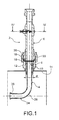
figure 1 est une vue générale en coupe d'une sonde iso-cinétique conforme à la présente invention ; - la
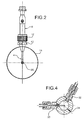
figure 2 est une vue extérieure de la sonde iso-cinétique représentée sur lafigure 1 ; - la
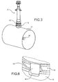
figure 3 est une vue en perspective de la sonde iso-cinétique représentée sur lesfigures 1 et2 ; - la
figure 4 est une vue en coupe selon le plan IV-IV de lafigure 1 ; - la
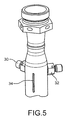
figure 5 est une vue extérieure en perspective de l'extrémité supérieure de la sonde de l'invention ; - la
figure 6 est une vue de détails d'un système de détrompage et d'anti-rotation ; - les
figures 7 à 9 sont trois vues en coupe d'une sonde iso-cinétique conforme à la présente invention avec des diamètres de tubes de prélèvement de diamètres décroissants.
- the
figure 1 is a general sectional view of an isokinetic probe according to the present invention; - the
figure 2 is an external view of the iso-kinetic probe shown on thefigure 1 ; - the
figure 3 is a perspective view of the iso-kinetic probe shown onfigures 1 and2 ; - the
figure 4 is a sectional view along plane IV-IV of thefigure 1 ; - the
figure 5 is an external perspective view of the upper end of the probe of the invention; - the
figure 6 is a detail view of a keying and anti-rotation system; - the
Figures 7 to 9 are three sectional views of an iso-kinetic probe according to the present invention with diameters of sampling tubes of decreasing diameters.
La sonde iso-cinétique de l'invention, désignée par la référence générale 2, se compose d'un tube de prélèvement 4 et d'une chambre de mesure 6. Le tube de prélèvement 4 comporte une extrémité aval 8 dont une embase 10 est solidaire. L'embase 10 est par exemple brasée ou soudée à l'extrémité 8 du tube de prélèvement. L'embase 10 possède un diamètre extérieur qui est ajusté dans le diamètre intérieur d'une douille de passage 12. La douille de passage 12 est elle-même fixée, par exemple soudée ou brasée, à l'extérieur d'un conduit 14 de grand diamètre.The iso-kinetic probe of the invention, designated by the
L'embase 10 possède une extrémité évasée, conique dans l'exemple de réalisation représenté 16. Cette partie conique vient en appui sur une partie conique complémentaire 18 de la douille de passage 12. L'extrémité inférieure de la chambre de mesure comporte un ajutage 20 qui vient en appui contre la partie intérieure de la partie conique 16. L'ajutage 20 est lui-même maintenu serré par un écrou 22. Ainsi, la partie conique 16 est prise entre la partie conique 18 de la douille de passage 12 et l'extrémité conique de l'ajutage 20.The
Le tube de prélèvement 4 possède une extrémité amont 24 qui comporte une embouchure (26) et une partie coudée 28. Comme on peut le voir sur les
L'extraction du tube de prélèvement s'effectue de la manière suivante. Tout d'abord, on desserre et on retire l'écrou 22 qui comporte une partie filetée en prise avec la douille de passage 12. L'écrou étant dévissé, on retire la chambre de mesure (6) ce qui libère l'embase 10. Il est alors possible de retirer le tube de prélèvement 4 dans son ensemble en le faisant passer à travers la douille de passage 12. Il convient de noter que, à cet effet, le diamètre intérieur d de l'alésage prévu dans la douille de passage est suffisamment grand pour permettre le passage de la partie coudée 28 du tube ainsi que de son embouchure 26, laquelle présente une forme évasée.The extraction of the sampling tube is carried out as follows. First of all, the
Le remontage du tube, ou le montage d'un nouveau tube, s'effectue en sens inverse. On constate ainsi que l'on peut changer rapidement le tube de prélèvement 4 sans avoir accès à l'intérieur du conduit 14.The reassembly of the tube, or the assembly of a new tube, is carried out in opposite direction. It can thus be seen that the
On a représenté sur la
La connaissance de la pression totale, de la pression statique et de la température permet le calcul du débit par les équations de Bernouilli. La connaissance du débit permet de calculer la vitesse pour une géométrie donnée. Le fait de connaître la vitesse du fluide au niveau de la chambre de mesure permet, par des équations de conservation du débit, de connaître la vitesse en amont, c'est-à-dire à l'embouchure 26 du tube de prélèvement 4.The knowledge of the total pressure, the static pressure and the temperature makes it possible to calculate the flow rate by the Bernouilli equations. The knowledge of the flow rate makes it possible to calculate the speed for a given geometry. The fact of knowing the speed of the fluid at the level of the measuring chamber makes it possible, by flow conservation equations, to know the speed upstream, that is to say at the
Afin de garantir une orientation-angulaire de l'embouchure 26 du trou parfaitement alignée avec l'axe longitudinal du conduit circulaire 14, on a prévu des moyens d'orientation angulaire. Dans l'exemple de réalisation représenté, ces moyens sont constitués par une gorge 40 formée de la douille de passage 12 et par un ergot 42 formé dans la partie conique 16 de l'embase 10. Lorsque l'ergot 42 est introduit dans la gorge 40, on est assuré que l'embouchure 26 présente la bonne orientation angulaire par rapport au conduit 14. Par ailleurs, l'ergot 42 empêche le tube de prélèvement de tourner par rapport à la douille de passage 12. L'ergot 42 assure donc en même temps une fonction anti-rotation.In order to guarantee an angular orientation of the
On a représenté sur les
Claims (11)
- Iso-kinetic probe, particularly for the analysis of the pollution of gases generated by an aircraft engine, comprising an air tapping tube having an upstream end (24) inserted into a conduit (14) wherein a gas stream flows, gas stream inlet velocity adjustment means being provided at an orifice of the tapping tube, characterised in that the tube (4) has a downstream end mounted in a fixed manner on a base (10), said base (10) having an outer diameter mounted in an inner diameter d of a passage bushing (12), the inner diameter of the passage bushing being sufficiently great so that the upstream end (24) of the tube (4) is suitable to fit through the inner diameter of the passage bushing (12), the probe also comprising a measurement chamber (6) having an end connected to the base.
- Iso-kinetic probe according to claim 1, characterised in that the upstream end (24) of the sampling tube is curved.
- Iso-kinetic probe according to claim 1 or 2, characterised in that the base (10) has a flared part (16) which is inserted in a corresponding flared part (18) of the passage bushing (12).
- Iso-kinetic probe according to claim 3, characterised in that the flared part of the base is held firmly in place resting on the flared part (18) of the passage bushing by means of a nut (22).
- Iso-kinetic probe according to claim 4, characterised in that the measurement'chamber hats an end tapered with a nozzle (20), said nozzle being held firmly in place resting on the flared part of the base by means of the nut (22).
- Iso-kinetic probe according to claim 1, characterised in that it comprises, provided in the measurement chamber (6), static pressure, total pressure and temperature measurement means (30, 32, 34).
- Iso-kinetic probe according to claim 6, characterised in that the total pressure measurement means is a Pitot tube (30).
- Iso-kinetic probe according to claim 6 or 7, characterised in that the temperature measurement means consists of a thermocouple.
- Iso-kinetic probe according to any of claims 1 or 2, characterised in that it comprises several tapping tubes (4a, 4b, 4c) having upstream ends of different diameters, said tapping tubes each being mounted on a base of a common outer diameter d, said diameter being sufficiently great so that the curved end of the tube with the greatest diameter (4a) is suitable to fit through the inner diameter of the passage bushing (12).
- Iso-kinetic probe according to any of claims 1 or 2, characterised in that it comprises at least one intake pump connected to the measurement chamber, said pump making it possible to adjust the gas intake velocity of at the orifice of the tapping tube (26).
- Iso-kinetic probe according to any of claims 1 or 2, characterised in that it comprises a diaphragm making it possible to vary the passage cross-section at the inlet of the end of the air tapping tube.
Applications Claiming Priority (1)
| Application Number | Priority Date | Filing Date | Title |
|---|---|---|---|
| FR0758751A FR2923014B1 (en) | 2007-10-31 | 2007-10-31 | ISO-KINETIC PROBE FOR THE ANALYSIS OF GAS POLLUTION GENERATED BY AN AIRCRAFT ENGINE |
Publications (2)
| Publication Number | Publication Date |
|---|---|
| EP2058641A1 EP2058641A1 (en) | 2009-05-13 |
| EP2058641B1 true EP2058641B1 (en) | 2010-05-26 |
Family
ID=39516302
Family Applications (1)
| Application Number | Title | Priority Date | Filing Date |
|---|---|---|---|
| EP08167593A Active EP2058641B1 (en) | 2007-10-31 | 2008-10-27 | Isokinetic probe for analysing pollution in the gases generated by an airplane engine |
Country Status (7)
| Country | Link |
|---|---|
| US (1) | US8171807B2 (en) |
| EP (1) | EP2058641B1 (en) |
| JP (1) | JP5188358B2 (en) |
| CA (1) | CA2642306C (en) |
| DE (1) | DE602008001352D1 (en) |
| FR (1) | FR2923014B1 (en) |
| RU (1) | RU2478927C2 (en) |
Families Citing this family (8)
| Publication number | Priority date | Publication date | Assignee | Title |
|---|---|---|---|---|
| PL2352982T3 (en) * | 2008-11-06 | 2016-03-31 | Kaminska Dorota | Method for measuring dust concentration in flowing gas and device for measuring dust concentration in flowing gas |
| US8234935B2 (en) * | 2010-10-28 | 2012-08-07 | Hamilton Sundstrand Corporation | Anti-rotation mechanism for pitot tube |
| US9473948B2 (en) | 2012-05-28 | 2016-10-18 | Huawei Technologies Co., Ltd. | Method and apparatus for analyzing pilot pollution |
| FR3012216B1 (en) * | 2013-10-18 | 2017-04-21 | Snecma | METHOD AND DEVICE FOR MEASURING POLLUTANTS CONTAINED IN THE EXHAUST OF AN ENGINE |
| CN103913353B (en) * | 2014-04-10 | 2016-04-13 | 北京大学 | A kind of gas normal pressure sampling apparatus being applicable to airborne measurement |
| WO2015159193A1 (en) | 2014-04-14 | 2015-10-22 | National Research Council Of Canada | Air sensor with downstream facing ingress to prevent condensation |
| KR102002967B1 (en) * | 2017-09-05 | 2019-10-01 | 주식회사 정엔지니어링 | An exhaust gas continuous isokinetic sampling apparatus with a sectional area adjustment device attached to the suction nozzle |
| CN108548700B (en) * | 2018-03-16 | 2019-07-23 | 华中科技大学 | A kind of Non-water-cooled high-temperature aerosol quantitatively dilutes sampling probe |
Family Cites Families (21)
| Publication number | Priority date | Publication date | Assignee | Title |
|---|---|---|---|---|
| US3252323A (en) * | 1961-12-29 | 1966-05-24 | Litton Systems Inc | Particulate sampling device |
| US3395516A (en) * | 1964-01-31 | 1968-08-06 | Navy Usa | Airborne aerosol collector |
| US3707869A (en) * | 1971-06-09 | 1973-01-02 | Atomic Energy Commission | Airborne isokinetic sampler |
| US3793887A (en) * | 1972-12-05 | 1974-02-26 | Ford Motor Co | Isokinetic sampling probe |
| US3965748A (en) * | 1974-11-18 | 1976-06-29 | Rader Companies, Inc. | Apparatus for automatically measuring particulate emissions in gas flow |
| US4034611A (en) * | 1976-12-03 | 1977-07-12 | The United States Of America As Represented By The Secretary Of The Navy | Particulate sampling probe |
| US4276092A (en) * | 1979-12-03 | 1981-06-30 | Lafarge Consultants Ltd. | Manufacture of cement |
| JPH0375541A (en) * | 1989-08-17 | 1991-03-29 | Mitsuo Samata | Dust measuring method |
| US4998954A (en) * | 1990-01-19 | 1991-03-12 | Union Carbide Industrial Gases Technology Corporation | Isokinetic probe and pressure reduction assembly |
| JP2581382Y2 (en) * | 1990-11-19 | 1998-09-21 | 株式会社 堀場製作所 | Constant flow gas sampling device |
| JP2754948B2 (en) * | 1991-05-02 | 1998-05-20 | 日立電線株式会社 | Oil circulation structure |
| JP2597692Y2 (en) * | 1993-07-29 | 1999-07-12 | 濁川理化工業株式会社 | Dust sampling device in exhaust gas |
| TW486565B (en) * | 1998-01-23 | 2002-05-11 | Miura Kogyo Kk | Sampling apparatus for chlorinated organic compounds |
| RU2158421C2 (en) * | 1999-01-29 | 2000-10-27 | Конструкторское Бюро Общего Машиностроения | Device for gas sampling |
| JP2000338014A (en) * | 1999-05-31 | 2000-12-08 | Miura Co Ltd | Sample collecting device for analyzing chlorinated organic compound |
| JP2001318033A (en) * | 2000-05-11 | 2001-11-16 | Tokyo Gas Co Ltd | Device for sampling solid particles |
| RU2193178C2 (en) * | 2001-01-16 | 2002-11-20 | Федеральное государственное унитарное предприятие Конструкторское бюро общего машиностроения им. В.П.Бармина | High-pressure gas sampler |
| JP3673854B2 (en) * | 2001-05-11 | 2005-07-20 | 独立行政法人産業技術総合研究所 | Dust sampling device with variable aperture suction nozzle |
| RU2230307C1 (en) * | 2002-10-15 | 2004-06-10 | Федеральное государственное унитарное предприятие "Конструкторское бюро общего машиностроения им. В.П. Бармина" | Method of monitoring of aerosol contamination of gases fed for thermostatt ing of carrier rockets and spacecrafts |
| US7610793B2 (en) * | 2006-09-11 | 2009-11-03 | Cummins Filtration Ip Inc. | Residence time chamber and sampling apparatus |
| RU60724U1 (en) * | 2006-09-26 | 2007-01-27 | Федеральное Государственное Унитарное предприятие "Конструкторское бюро общего машиностроения имени В.П. Бармина" | GAS SAMPLING DEVICE |
-
2007
- 2007-10-31 FR FR0758751A patent/FR2923014B1/en not_active Expired - Fee Related
-
2008
- 2008-10-22 US US12/256,130 patent/US8171807B2/en active Active
- 2008-10-24 JP JP2008273882A patent/JP5188358B2/en active Active
- 2008-10-27 DE DE602008001352T patent/DE602008001352D1/en active Active
- 2008-10-27 EP EP08167593A patent/EP2058641B1/en active Active
- 2008-10-29 CA CA2642306A patent/CA2642306C/en active Active
- 2008-10-30 RU RU2008143115/05A patent/RU2478927C2/en active
Also Published As
| Publication number | Publication date |
|---|---|
| FR2923014B1 (en) | 2009-12-25 |
| FR2923014A1 (en) | 2009-05-01 |
| RU2008143115A (en) | 2010-05-10 |
| JP2009133839A (en) | 2009-06-18 |
| US20100043573A1 (en) | 2010-02-25 |
| CA2642306A1 (en) | 2009-04-30 |
| CA2642306C (en) | 2016-01-26 |
| EP2058641A1 (en) | 2009-05-13 |
| DE602008001352D1 (en) | 2010-07-08 |
| JP5188358B2 (en) | 2013-04-24 |
| RU2478927C2 (en) | 2013-04-10 |
| US8171807B2 (en) | 2012-05-08 |
Similar Documents
| Publication | Publication Date | Title |
|---|---|---|
| EP2058641B1 (en) | Isokinetic probe for analysing pollution in the gases generated by an airplane engine | |
| CA2799694C (en) | Device for multipoint acquisition/distribution of fluid, in particular probe for tapping pressure in a turbomachine air inlet | |
| EP2113084A2 (en) | Device for measuring the total pressure of a flow and method using said device | |
| CA2838187C (en) | Device and method for a test sample, specifically for identifying a gas in a sample | |
| EP3301428B1 (en) | Rake for measuring gas parameters at the outlet of a turbine engine flow section | |
| FR2930588A1 (en) | COMPRESSOR ROTOR OF A TURBOMACHINE HAVING CENTRIFIC AIR-LEVELING MEANS | |
| FR3025885A1 (en) | DEVICE FOR MEASURING AERODYNAMIC SIZES FOR PLACING IN A FLOWING VEHIC OF A TURBOMACHINE | |
| FR3038981A1 (en) | DEVICE FOR MEASURING AERODYNAMIC SIZES FOR PLACING IN A FLOWING VEHIC OF A TURBOMACHINE | |
| FR3066779A1 (en) | DEVICE FOR MEASURING PARAMETERS OF AERODYNAMIC FLOW FOR TURBOMACHINE BLADE, BLADE AND TURBOMACHINE MEMBER EQUIPPED WITH SAID MEASURING DEVICE | |
| FR3053786A1 (en) | DEVICE FOR MEASURING AERODYNAMIC SIZES FOR PLACING IN A FLOWING VEHIC OF A TURBOMACHINE | |
| FR3044412A1 (en) | INSTRUMED VEIN OF TURBOMACHINE | |
| FR3073287A1 (en) | IMPROVED TEST DEVICE FOR TURBOMACHINE | |
| FR3084160A1 (en) | DEVICE FOR MEASURING THE TEMPERATURE OF AN AERODYNAMIC FLOW IN A TURBOMACHINE VEIN AND TURBOMACHINE EQUIPPED WITH SUCH A DEVICE | |
| FR2945837A1 (en) | Fuel supply rail for combustion/post-combustion chamber of e.g. jet engine of aircraft, has duct whose section decreases from inlet until part of duct diametrically opposed to inlet so as to standardize rate flow on circumference of duct | |
| WO1997013153A1 (en) | Device for controlling and/or measuring intake swirl in a reciprocating heat engine combustion chamber | |
| FR2952178A1 (en) | Oil i.e. hot lubricating oil, average flow measuring module for spark ignition engine of motor vehicle, has hollow body including inner surface, and recovery unit that recovers oil flowing on inner surface of hollow body | |
| FR3139901A1 (en) | Tool for measuring physical quantities of a flow of fluid circulating in a flow vein. | |
| FR3064745A1 (en) | DEVICE FOR MEASURING CHARACTERISTICS OF AN AIR FLOW | |
| FR2891620A1 (en) | Fluid e.g. air, flow sensor for inlet line of internal combustion engine of motor vehicle, has small size target, coupled to rod end in rigid way, with airfoil having leading edge oriented perpendicularly to main direction of fluid flow | |
| EP1669130A1 (en) | Calibration device for Gasanalyser and related method | |
| EP3374741B1 (en) | Apparatus for estimating the volume of fluid flowing in a pipe | |
| FR3140166A1 (en) | Removable two-part turbomachine pressure probe | |
| FR3111704A1 (en) | DEVICE FOR MEASURING A PHYSICAL PARAMETER IN A TEST BENCH OF AN AIRCRAFT TURBOMACHINE, AND ASSOCIATED TEST BENCH | |
| BE404922A (en) | ||
| FR2896566A1 (en) | Tracer gas flow regulator for tracer gas injection system, has orifices located on positioning disk and ensuring communication between outlet of upstream circuit and inlet of downstream circuit, where orifices have equal diameter |
Legal Events
| Date | Code | Title | Description |
|---|---|---|---|
| PUAI | Public reference made under article 153(3) epc to a published international application that has entered the european phase |
Free format text: ORIGINAL CODE: 0009012 |
|
| AK | Designated contracting states |
Kind code of ref document: A1 Designated state(s): AT BE BG CH CY CZ DE DK EE ES FI FR GB GR HR HU IE IS IT LI LT LU LV MC MT NL NO PL PT RO SE SI SK TR |
|
| AX | Request for extension of the european patent |
Extension state: AL BA MK RS |
|
| 17P | Request for examination filed |
Effective date: 20091023 |
|
| GRAP | Despatch of communication of intention to grant a patent |
Free format text: ORIGINAL CODE: EPIDOSNIGR1 |
|
| RIN1 | Information on inventor provided before grant (corrected) |
Inventor name: HARIVEL, NADINE, ALICE, HELENE Inventor name: CARICHON, SEBASTIEN Inventor name: DEL ARCO, SERGE |
|
| AKX | Designation fees paid |
Designated state(s): DE FR GB |
|
| GRAS | Grant fee paid |
Free format text: ORIGINAL CODE: EPIDOSNIGR3 |
|
| GRAA | (expected) grant |
Free format text: ORIGINAL CODE: 0009210 |
|
| AK | Designated contracting states |
Kind code of ref document: B1 Designated state(s): DE FR GB |
|
| REG | Reference to a national code |
Ref country code: GB Ref legal event code: FG4D Free format text: NOT ENGLISH |
|
| REF | Corresponds to: |
Ref document number: 602008001352 Country of ref document: DE Date of ref document: 20100708 Kind code of ref document: P |
|
| PLBE | No opposition filed within time limit |
Free format text: ORIGINAL CODE: 0009261 |
|
| STAA | Information on the status of an ep patent application or granted ep patent |
Free format text: STATUS: NO OPPOSITION FILED WITHIN TIME LIMIT |
|
| 26N | No opposition filed |
Effective date: 20110301 |
|
| REG | Reference to a national code |
Ref country code: DE Ref legal event code: R097 Ref document number: 602008001352 Country of ref document: DE Effective date: 20110228 |
|
| REG | Reference to a national code |
Ref country code: FR Ref legal event code: PLFP Year of fee payment: 8 |
|
| REG | Reference to a national code |
Ref country code: FR Ref legal event code: PLFP Year of fee payment: 9 |
|
| REG | Reference to a national code |
Ref country code: FR Ref legal event code: PLFP Year of fee payment: 10 |
|
| REG | Reference to a national code |
Ref country code: FR Ref legal event code: CD Owner name: SNECMA, FR Effective date: 20170713 |
|
| REG | Reference to a national code |
Ref country code: FR Ref legal event code: PLFP Year of fee payment: 11 |
|
| PGFP | Annual fee paid to national office [announced via postgrant information from national office to epo] |
Ref country code: GB Payment date: 20230920 Year of fee payment: 16 |
|
| PGFP | Annual fee paid to national office [announced via postgrant information from national office to epo] |
Ref country code: FR Payment date: 20230920 Year of fee payment: 16 |
|
| PGFP | Annual fee paid to national office [announced via postgrant information from national office to epo] |
Ref country code: DE Payment date: 20230920 Year of fee payment: 16 |