EP2058553A1 - Assembling device, assembling method, and production method for power transmission belt - Google Patents
Assembling device, assembling method, and production method for power transmission belt Download PDFInfo
- Publication number
- EP2058553A1 EP2058553A1 EP07806175A EP07806175A EP2058553A1 EP 2058553 A1 EP2058553 A1 EP 2058553A1 EP 07806175 A EP07806175 A EP 07806175A EP 07806175 A EP07806175 A EP 07806175A EP 2058553 A1 EP2058553 A1 EP 2058553A1
- Authority
- EP
- European Patent Office
- Prior art keywords
- ring
- recess
- rings
- elements
- element array
- Prior art date
- Legal status (The legal status is an assumption and is not a legal conclusion. Google has not performed a legal analysis and makes no representation as to the accuracy of the status listed.)
- Granted
Links
Images






Classifications
-
- F—MECHANICAL ENGINEERING; LIGHTING; HEATING; WEAPONS; BLASTING
- F16—ENGINEERING ELEMENTS AND UNITS; GENERAL MEASURES FOR PRODUCING AND MAINTAINING EFFECTIVE FUNCTIONING OF MACHINES OR INSTALLATIONS; THERMAL INSULATION IN GENERAL
- F16G—BELTS, CABLES, OR ROPES, PREDOMINANTLY USED FOR DRIVING PURPOSES; CHAINS; FITTINGS PREDOMINANTLY USED THEREFOR
- F16G5/00—V-belts, i.e. belts of tapered cross-section
- F16G5/16—V-belts, i.e. belts of tapered cross-section consisting of several parts
-
- B—PERFORMING OPERATIONS; TRANSPORTING
- B29—WORKING OF PLASTICS; WORKING OF SUBSTANCES IN A PLASTIC STATE IN GENERAL
- B29D—PRODUCING PARTICULAR ARTICLES FROM PLASTICS OR FROM SUBSTANCES IN A PLASTIC STATE
- B29D29/00—Producing belts or bands
- B29D29/10—Driving belts having wedge-shaped cross-section
-
- F—MECHANICAL ENGINEERING; LIGHTING; HEATING; WEAPONS; BLASTING
- F16—ENGINEERING ELEMENTS AND UNITS; GENERAL MEASURES FOR PRODUCING AND MAINTAINING EFFECTIVE FUNCTIONING OF MACHINES OR INSTALLATIONS; THERMAL INSULATION IN GENERAL
- F16H—GEARING
- F16H9/00—Gearings for conveying rotary motion with variable gear ratio, or for reversing rotary motion, by endless flexible members
- F16H9/02—Gearings for conveying rotary motion with variable gear ratio, or for reversing rotary motion, by endless flexible members without members having orbital motion
- F16H9/24—Gearings for conveying rotary motion with variable gear ratio, or for reversing rotary motion, by endless flexible members without members having orbital motion using chains or toothed belts, belts in the form of links; Chains or belts specially adapted to such gearing
-
- Y—GENERAL TAGGING OF NEW TECHNOLOGICAL DEVELOPMENTS; GENERAL TAGGING OF CROSS-SECTIONAL TECHNOLOGIES SPANNING OVER SEVERAL SECTIONS OF THE IPC; TECHNICAL SUBJECTS COVERED BY FORMER USPC CROSS-REFERENCE ART COLLECTIONS [XRACs] AND DIGESTS
- Y10—TECHNICAL SUBJECTS COVERED BY FORMER USPC
- Y10T—TECHNICAL SUBJECTS COVERED BY FORMER US CLASSIFICATION
- Y10T29/00—Metal working
- Y10T29/49—Method of mechanical manufacture
- Y10T29/49826—Assembling or joining
- Y10T29/49863—Assembling or joining with prestressing of part
-
- Y—GENERAL TAGGING OF NEW TECHNOLOGICAL DEVELOPMENTS; GENERAL TAGGING OF CROSS-SECTIONAL TECHNOLOGIES SPANNING OVER SEVERAL SECTIONS OF THE IPC; TECHNICAL SUBJECTS COVERED BY FORMER USPC CROSS-REFERENCE ART COLLECTIONS [XRACs] AND DIGESTS
- Y10—TECHNICAL SUBJECTS COVERED BY FORMER USPC
- Y10T—TECHNICAL SUBJECTS COVERED BY FORMER US CLASSIFICATION
- Y10T29/00—Metal working
- Y10T29/53—Means to assemble or disassemble
- Y10T29/53978—Means to assemble or disassemble including means to relatively position plural work parts
Definitions
- This invention relates to an assembling device, an assembling method and a manufacturing method of a driving belt, in which a plurality of plate elements interlinked with one another in a circular manner is fastened by an endless annular ring.
- a geared transmission capable of changing a gear stage thereof stepwise, and a continuously variable transmission capable of varying a speed change ratio steplessly are available as a transmission mechanism for transmitting power between rotary members.
- a belt-type continuously variable transmission and a toroidal-type continuously variable transmission are known as the continuously variable transmission.
- the belt-type continuously variable transmission is a transmission varying a speed change ratio continuously using a pair of drive pulleys and a pair of driven pulleys, and a driving belt applied to those pulleys.
- the known endless driving belt used in such belt-type continuously variable transmission is prepared by arranging a plurality of plate members called an "element” or a “block” in a circular manner while connecting the plate members with one another, and fastening the interlinked plate members by an annular belt called a "band” or a “carrier”.
- the "High-Loaded Transmission Belt” taught by Japanese Patent Laid-Open No. 2000-249195 is composed of a center belt and blocks reinforced against lateral pressure, and it is applied to a main prime mover and an auxiliary prime mover of automobiles and agricultural machineries.
- the "High-Loaded Transmission Belt” comprises a block (i.e., an element) which is so constituted that two belt sides having lock parts in its top end are connected to each other in their bottom ends by a connecting member, and two rows of endless carriers (i.e., rings) fixedly fitted into an engagement groove opening between the lock parts.
- the belt side portion of the element is provided individually with a convex portion and a concave portion on each face so that the elements can interlink with one another. Therefore, the interlinked elements can be aligned even when the belt is running.
- Japanese Patent Laid-Open No. 2001-193796 discloses an invention relating to "Element for Metal Belt and Metal Belt” for continuously variable transmissions of vehicles.
- the metal belt taught by Japanese Patent Laid-Open No. 2001-193796 comprises: a metal endless band (i.e., a ring) applied to annular grooves of a drive and a driven pulleys; a plurality of metal element composed of a body portion to be contacted with the annular groove of the pulley, a pair of pillars erected on the body portion and faced with each other, an engagement protruded portion formed on a leading end of the pillar, and an opening for inserting the band (i.e., a recessed portion) formed between the engagement protruded portions; and an endless metal falling preventing body somewhat wider than the band.
- the falling preventing body can be bent to narrow its width when it is inserted in between the engagement protruded portions to prevent falling of the band.
- Japanese Patent Laid-Open No. 2000-205345 discloses a "Method and Device for Assembling CVT Belt".
- a plurality of platelike elements comprising a pair of grooves on both lateral sides are accumulated in the thickness direction thereof to form an annular element assembly, and two rings are inserted into grooves of the element assembly held by a linear dummy ring member being arranged annularly.
- the lock parts are formed on both belt sides of the element erected beside the carriers to hold the carriers on the element, and the convex portion and the concave portion are formed individually on an upper corner of each face of the belt sides to interlink adjoining elements. That is, the convex portion and concave portion functioning as male and female connections are formed symmetrically on both upper corner of the element.
- the carriers are individually fitted into each engagement groove and held by the lock part so that two rows of the belts are held in the element.
- the carriers arranged parallel to each other have to be overlapped partially when fitted onto the elements or dismounted from the elements. That is, a total width of the carriers arranged parallel to each other have to be reduced narrower than the opening width between the lock parts of the element when the carriers are fitted onto the elements or dismounted from the elements, by twisting the carriers to overlap partially.
- the two rows of the rings have to be fitted into the recess of large number of element, for example, about 400 pieces of the elements. This means that it will take long time for assembling a driving belt by fitting the ring into the recess of the element piece by piece by hand, or fitting the ring into the recess of every several pieces of the element by hand.
- a length of time to assemble the driving belt may be varied depending on the person.
- productivity of the driving belt still has to be improved by fitting the ring into the recess of the elements in a systematic manner.
- the present invention has been conceived noting the technical problems thus far described, and its object is to provide an assembling device, an assembling method and a manufacturing method of a driving belt capable of fitting the ring into the recess of the elements easily and efficiently to improve a productivity of the driving belt.
- an assembling device of a driving belt in which a plurality of elements is interlinked annularly in a manner to situate a recess thereof to open to an outer circumferential side, and in which a first ring and a second ring are accommodated parallel to each other in the recess of the element, and held in an inner circumferential side of protruding portions formed on an opening end side of inner walls of the recess to prevent detachment of the rings, comprising: a ring holding mechanism immovably holding the first ring being fitted in an inner circumferential side of one of the protruding portions in the recess; and a ring moving mechanism for moving the second ring relatively to the first ring close toward other protruding portion.
- assembling device of a driving belt further comprises an element holding mechanism for holding a plurality of elements in a form of element array in which the elements are juxtaposed to each other in its thickness direction.
- first ring is to be overlapped inside of the second ring and the second ring is to be overlapped outside of the first ring, when those rings are overlapped in its thickness direction by buckling one of the rings partially.
- an assembling device of a driving belt in which a plurality of elements is interlinked annularly in a manner to situate a recess thereof to open to an outer circumferential side, and in which a first ring and a second ring are accommodated parallel to each other in the recess of the element, and held in an inner circumferential side of protruding portions formed on an opening end side of inner walls of the recess to prevent detachment of the rings, comprising: an element holding member for holding the plurality of elements in a form of an element array, in which the elements are juxtaposed in its thickness direction and directed to open the recess thereof.
- the above-mentioned element holding member is made of a flexible material. That is, the element holding member is capable of winding into a circle or an arc in its length direction thereby holding and releasing the element array.
- the element holding member comprises side walls for restricting a lateral movement of the element array held therein by contacting with lateral faces of the element array, and divider walls for restricting a longitudinal movement of the element array held therein by contacting with a front face or a rear face of the element array.
- an assembling method of a driving belt in which a plurality of elements is interlinked annularly in a manner to situate a recess thereof to open to an outer circumferential side, and in which a first ring and a second ring are accommodated parallel to each other in the recess of the element, and held in an inner circumferential side of protruding portions formed on an opening end side of inner walls of the recess to prevent detachment of the rings, comprising: overlapping the first and second rings in its thickness direction by buckling one of the rings partially; holding the first ring overlapped inside of the second ring immovably while fitting the first ring in an inner circumferential side of one of the protruding portions in the recess; and thereafter fitting the second ring overlapped outside of the first ring in an inner circumferential side of other protruding portion in the recess by moving second ring toward other protruding portion.
- the plurality of elements are held in the form of element array in which the elements are juxtaposed in its thickness direction in advance.
- an assembling method of a driving belt in which a plurality of elements is interlinked annularly in a manner to situate a recess thereof to open to an outer circumferential side, and in which a first ring and a second ring are accommodated parallel to each other in the recess of the element, and held in an inner circumferential side of protruding portions formed on an opening end side of inner walls of the recess to prevent detachment of the rings, comprising: holding the plurality of elements in a form of an element array in which the elements are juxtaposed to each other in its thickness direction and directed to open the recess thereof; overlapping the first and the second rings in its thickness direction, or overlapping the first and the second rings in its thickness direction partially in its length direction, by buckling one of the rings partially; inserting the overlapped rings or an overlapped portion of the rings into the recess of the element array being held; fitting the first and second rings respectively in the inner circumferential side of the
- the element array is held by an element holding member made of a flexible material. That is, the element holding member is capable of winding into a circle or an arc in its length direction thereby holding and releasing the element array.
- the assembling method of a driving belt of the invention further comprising: holding the plurality of elements in the form of element array in which the elements are juxtaposed to each other in its thickness direction and directed to open the recess thereof; inserting a portion of the rings overlapped partially in its length direction into the recess of the element array being held; fitting the first and the second rings in an inner circumferential side of the protruding portions in the recess, by moving the element array accommodating the overlapped portion of the rings in its recess along the length direction of the rings to a portion where the first and the second rings are aligned parallel to each other, or by aligning the partially overlapped first and second rings to be parallel to each other in its entire length; and thereafter releasing the plurality of elements being held in the form of the element array.
- the element array is held by an element holding member made of a flexible material. That is, the element holding member is capable of winding into a circle or an arc in its length direction thereby holding and releasing the element array.
- a manufacturing method of a driving belt in which a first ring and a second ring are accommodated parallel to each other in a recess of a plurality of elements, and in which the rings are held by protruding portions formed on an opening end side of inner walls of the recess to prevent detachment of the rings from the recess, comprising: arranging the plurality of elements annularly in a manner to situate the recess to open to an outer circumferential side; overlapping the first and the second rings in its thickness direction by buckling one of the rings partially; holding the first ring overlapped inside of the second ring immovably in the recess of the elements arranged annularly while fitting the first ring in an inner circumferential side of one of the protruding portion; and thereafter fitting the second ring overlapped outside of the first ring in an inner circumferential side of other protruding portion by moving the second ring close toward the other protruding portion.
- the plurality of elements is held in a form of element array in which the elements are juxtaposed in its thickness direction in advance.
- a manufacturing method of a driving belt in which a first ring and a second ring are accommodated parallel to each other in a recess of a plurality of elements, and in which the rings are held by protruding portions formed on an opening end side of inner walls of the recess to prevent detachment of the rings from the recess, comprising: holding the plurality of elements in a form of element array in which the elements are juxtaposed annularly to each other in its thickness direction in a manner to situate the recess to open to an outer circumferential side; overlapping the first and the second rings in its thickness direction, or overlapping the first and the second rings in its thickness direction partially in its length direction, by buckling one of the rings partially; inserting the overlapped rings or an overlapped portion of the rings into the recess of the element array being held; fitting the first and second rings respectively in the inner circumferential side of the protruding portions in the recess, by fitting the first ring
- the element array is held by an element holding member made of a flexible material. That is, the element holding member is capable of winding into a circle or an arc in its length direction thereby holding and releasing the element array.
- the manufacturing method of a driving belt of the invention further comprising: holding the plurality of elements in the form of element array in which the elements are juxtaposed to each other in its thickness direction and directed to open the recess thereof; inserting a portion of the rings overlapped partially in its length direction into the recess of the element array being held; fitting the first and the second rings in an inner circumferential side of the protruding portions in the recess, by moving the element array accommodating the overlapped portion of the rings in its recess along the length direction of the rings to a portion where the first and the second rings are aligned parallel to each other, or by aligning the partially overlapped first and second rings to be parallel to each other in its entire length; and thereafter releasing the plurality of elements being held in the form of the element array.
- the element array is held by an element holding member made of a flexible material. That is, the element holding member is capable of winding into a circle or an arc in its length direction thereby holding and releasing the element array.
- two rows of the rings such as the first and the second rings are thus accommodated in the recess of the plurality of elements. More specifically, the outer lateral side of the first ring is fitted into the clearance between one of the protruding portions and the bottom of the recess, and the first element is held immovably. On the other hand, the second ring is pushed relatively to the first ring, that is, pushed toward other protruding portion to be fitted into the clearance between the other protruding portion and the bottom of the recess. As a result, the two rows of rings are accommodated in the recess of the elements. Therefore, two rows of rings can be fitted into the recess of the plurality of the elements simultaneously. According to the present invention, therefore, the driving belt can be assembled efficiently, and the productivity of the driving belt is thereby improved.
- the plurality of elements is held in the form of element array in which the elements are juxtaposed to each other in its thickness direction. That is, the two rows of rings can be fitted into the recess of the plurality of elements being held in the form of the element array simultaneously and easily.
- the first ring and the second ring are thus overlapped in its thickness direction by buckling the first ring partially to be overlapped inside of the second ring. Therefore, the two rows of rings can be fitted into the recess of the plurality of elements simultaneously and easily.
- the plurality of elements is held in the form of an element array, in which the elements are juxtaposed in its thickness direction and directed to open the recess thereof. Therefore, the two rows of rings can be fitted into the recess of the plurality of the elements simultaneously while fitting those rings in the inner circumferential side of both of the protruding portions. As a result, the driving belt can be assembled efficiently and the productivity of the driving belt is thereby improved.
- the plurality of elements is held in the form of element array by the element holding member made of a flexible material and capable of winding into a circle or an arc in its length direction. Therefore, the two rows of rings can be fitted into the recess of the plurality of elements being held in the form of the element array simultaneously and easily.
- the element array is held properly by the side walls restricting a lateral movement of the elements and by the divider walls restricting a longitudinal movement of the elements. Therefore, the two rows of rings can be fitted into the recess of the plurality of elements simultaneously and easily.
- the first and second rings are overlapped in its thickness direction by buckling the first ring partially and situating the first ring inside of the second ring, and the overlapped rings are inserted into the recess of the elements.
- the outer lateral side of the first ring is fitted in the inner circumferential side of one of the protruding portions and held immovably.
- the second ring is pushed toward the other protruding portion to be fitted in the inner circumferential side of the other protruding portion.
- the two rows of rings are fitted properly in the recess of the element.
- the two rows of rings can be fitted into the recess of the plurality of elements simultaneously so that the driving belt can be assembled efficiently. Consequently, the productivity of the driving belt is improved.
- the plurality of elements is held in the form of element array in which the elements are juxtaposed in its thickness direction in advance. Therefore, the two rows of rings can be fitted into the recess of the plurality of elements simultaneously and easily.
- the plurality of elements is held in the form of element array in which the elements are juxtaposed to each other in its thickness direction and directed to open the recess thereof.
- the first and the second rings are overlapped partially or entirely in its length direction, and the overlapped rings or the overlapped portion of the rings are inserted into the recess of the element array. Then, the first ring is fitted in the inner circumferential side of one of the protruding portions, and the second ring is fitted in the inner circumferential side of the other protruding portion by pushing second ring toward other protruding portion.
- the first and second rings are fitted in the inner circumferential side of both of the protruding portions by moving the element array accommodating the overlapped rings in its recess along the length direction of the rings to the portion where the first and the second rings are aligned parallel to each other.
- the two rows of rings can be fitted into the recess of the plurality of elements simultaneously so that the driving belt can be assembled efficiently Consequently, the productivity of the driving belt is improved.
- the plurality of the elements is held in the form of element array by the member made of a flexible material capable of winding into a circle or an arc in its length direction thereby holding and releasing the element array. Therefore, the two rows of rings can be fitted into the recess of the plurality of elements simultaneously and easily.
- the plurality of elements is held in the form of element array in which the elements are juxtaposed in its thickness direction and directed to open the recess thereof.
- the outer lateral side of the first ring overlapped inside of the second ring is fitted into the clearance between one of the protruding portions and a bottom of the recess
- the outer lateral side of the second ring overlapped outside of the first ring is fitted into the clearance between other protruding portion and the bottom of the recess by moving second ring toward other protruding portion.
- the partially overlapped two rows of rings are aligned parallel to each other in its entire length, that is, the outer lateral sides of both rings are fitted into the clearances between the protruding portions and the bottom of the recess in its entire length.
- the remaining portion of the rings can also be fitted into the recess of the plurality of elements simultaneously and easily. That is, the two rows of rings can be fitted into the recess of the elements efficiently in almost entire length thereof, and the productivity of the driving belt is thereby improved.
- the elements to accommodate the remaining portion of the rings in its recess are held in the form of element array by the flexible member capable of winding into a circle or an arc in its length direction to hold and release the element array. Therefore, the two rows of rings can be fitted into the recess of the elements efficiently in almost entire length thereof, and the productivity of the driving belt is thereby improved.
- Fig. 16 shows an example of a driving belt V to be applied to a drive pulley (i.e., an input shaft side pulley) and a driven pulley (i.e., an output shaft side pulley) of a belt type continuously variable transmission so as to transmit a power between those pulleys.
- An element 1 is a metal plate member comprising a base portion (or main body) 4. Both lateral faces 2 and 3 of the base portion 4, that is, both lateral ends (in the direction of x-axis in Fig. 16 ) of the base portion 4 are inclined. The inclined lateral faces 2 and 3 are frictionally contacted with a V-shaped groove 5a of a drive or driven pulley 5 of the belt type continuously variable transmission to transmit a torque.
- the base portion 4 comprises columns 6 erected vertically (in the direction of y-axis in Figs. 16 and 17 ) at both lateral ends (in the direction of x-axis in Fig. 16 ) thereof. Accordingly, a recess 7 is formed by an upper face (or a top edge) 4a of the base portion 4 and both inner walls 6a of the columns 6 facing to the center of the base portion 4. Thus, the recess 7 opens upwardly, in other words, the recess 7 opens toward an outer circumference of the driving belt V
- the recess 7 is a space for accommodating an endless ring 8 for fastening the elements 1 interlinked closely with one another in a circular manner. That is, the upper face 4a functions as a saddle face 4a onto which an inner circumferential face of the ring 8 is fitted.
- the ring 8 is a layered ring made of metal comprising a plurality of annular belt-like layers overlapped in a circumferential direction.
- two rings 8a and 8b are arranged parallel to each other in the recess 7.
- a configuration, dimensions, material, strength and so on of the rings 8a and 8b are identical to each other.
- the element 1 comprises protruding portions 9.
- Each protruding portion 9 is formed integrally with the column 6 and protrudes toward a width center of the base portion 4 from an outer circumferential side of the columns 6, that is, both end faces 9a of the protruding portions 9 are faced inwardly to be opposed to each other.
- the protruding portion 9 is formed on both opening ends of the recess 7 above lateral ends of the ring 8a and 8b, i.e., on the end portions of the inner walls 6a, and both of the protruding portions 9 protrude toward a width center of the recess 7 (i.e., in the direction of x-axis in Fig. 16 ).
- a clearance between the end faces 9a is an opening width W1 of the recess 7.
- a width of the recess 7 at bottom portion 7a (i.e., the upper face 4a) side, specifically, a clearance between the inner walls 6a is wider than the opening width W1, and which is represented by W2.
- the elements 1 are interlinked with one another in a circular manner and fastened by the ring 8.
- the elements 1 thus fastened by the ring 8 is applied to the drive and driven pulleys 5.
- the driving belt V is applied to the pulleys 5
- clearances between the elements 1 are narrowed gradually toward a rotational center of the pulleys 5 in a region where the elements 1 are contacted with the pulleys 5, and the elements 1 are eventually contacted with one another at its portion close to the rotational center of the pulley 5.
- a thickness of the element 1 has to be thinned at its lower portion, that is, at the portion close to the rotational center of the pulley 5, as illustrated in Figs. 16 and 17 .
- one of the faces of the base portion 4 i.e., the left face in Fig. 17 is thinned gradually from a predetermined portion below the saddle face 4a.
- the elements 1 are contacted with the adjoining element 1 at the portion where the thickness thereof starts to be reduced, in the region where the elements 1 are contacted with the pulley 5, in other words, in a curving region of the belt V That is, an edge of a boundary of thickness functions as a rocking edge 10.
- a male connection 11 and a female connection 12 are respectively formed on each face of the base portion 4 being opposed to the adjoining element 1, at the center of width of the element 1.
- the male connection 11 of circular truncated cone is formed on one of the faces of the base portion 4 where the rocking edge 10 is formed.
- the bottomed cylindrical female connection 12 to which the adjoining male connection 11 is inserted loosely is formed on a face opposite to the face on which the male connection 11 is formed. Therefore, the elements 1 can be kept in line within a straight region of the belt V where the element 1 is not being contacted with the pulley 5.
- a relative position of the elements 1 within the straight region of the driving belt V can be determined in both vertical and horizontal directions in Fig. 16 by joining the male and female connections 11 and 12. For this reason, chattering of the driving belt V is prevented so that the belt V can be driven smoothly when the belt-type continuously variable transmission is driven.
- the element 1 comprises the recess 7 on its outer circumferential side of the driving belt V and the protruding portions 9 protruding toward the width center of the recess 7 are formed on opening ends of both of the inner walls of the columns 6.
- the male connection 11 protruding toward the adjoining element is formed on one of the faces of the element 1 being opposed to the adjoining element 1
- the female connection 12 into which the male connection is inserted loosely is formed on the face of the element 1 opposite to the face on which the male connection 11 is formed.
- one male connection 11 and one female connection 12 are respectively formed on each face of the element 1 being opposed to the adjoining element 1, at the center of width of the element 1.
- the elements 1 interlinked in a circular manner can swing relatively with each other, in other words, the interlinked elements 1 can pivot relatively with each other, as shown in Fig. 18 .
- the ring 8 comprises the first ring 8a and the second ring 8b. Therefore, as shown in Fig. 19 , the rings 8a and 8b can be overlapped partially (as shown in a circle A in Fig. 19 ) while keeping the remaining portion of the rings 8a and 8b parallel to each other (as shown in a circle B in Fig. 19 ).
- the first ring 8a and the second ring 8b are overlapped in its thickness direction by buckling one of the rings (i.e., the first ring 8a in Fig. 20 ) and situating the buckled ring inside of other ring (i.e., the second ring 8b in Fig. 20 ).
- a width L1 of the ring 8 i.e., a total width of the first ring 8a and the second ring 8b aligned parallel to each other is wider than the aforementioned opening width W1 but narrower than the width W2.
- the total width of the ring 8 can be reduced narrower than the opening width W1 by overlapping the first ring 8a and the second ring 8b entirely or partially in its length direction.
- the opening width W1 of the recess 7 is narrower than the width L1 of the ring 8, and the width W2 of the recess 7 is wider than the width L1 of the ring 8.
- the width L2 of the rings 8a and 8b overlapped entirely or partially in its length direction is narrower than the opening width W1 of the recess 7, and the width L1 of the rings 8a and 8b aligned parallel to each other is wider than the opening width W1 of the recess 7 but narrower than the width W2 of the recess 7.
- the ring 8 can be fitted into the recess 7 from the overlapped portion of the first ring 8a and the second ring 8b through the clearance between the end faces 9a.
- the element 1 is moved to the portion where the first ring 8a and the second ring 8b are aligned parallel to each other so that the first ring 8a and the second ring 8b can be fitted into the clearances between the protruding portions 9 and the bottom 7a of the recess 7 shown in the Figs 16 and 18 .
- the elements 1 are interlinked to the adjoining elements 1 in a circular manner being pivotable relative to each other. Therefore, the ring 8 can be twisted easily to be overlapped partially by a pivotal movement of the element 1 even at a stage in which relatively large number of elements 1 are holding the first ring 8a and the second ring 8b.
- a plurality of elements i.e., an element array
- one of the overlapped rings i.e., the first ring 8a situated inside of the second ring 8b as shown in Figs 20 and 21 is fitted into the clearance between one of the protruding portions 9 and the bottom 7a of the recess 7.
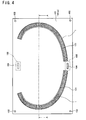
- column-shaped guide members 102 are fixedly erected substantially vertically.
- the guide members 102 are erected on four corners of rectangular upper (or top) face of the base member 101, as shown in Fig. 2 .
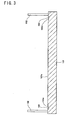
- element locking grooves 103 for holding the element array are formed on the upper face of the base member 101.
- the element locking groove 103 comprises an inclined face 103a whose inclination is identical to that of the lateral faces 2 and 3 of the element 1, and a cross-section thereof is a right triangle.
- the element array 1 in which the elements 1 are juxtaposed in the thickness direction is erected substantially vertically on the base face 101a, as shown in Figs. 4 and 5 .
- the element locking grooves 103 are formed on the portions where an outer face of the ring 8 overlapped inside of the ring 8b is contacted closely to an inner face of the ring 8b, except for regions where the overlapped ring 8a is partially buckled as represented by P in Fig. 20 and where after-mentioned ring pushing members 104 are actuated. Accordingly, the element array 1 can be erected on the base member 101 in the direction in which the width direction of the element 1 is substantially perpendicular to the base face 101a, while accommodating the overlapped ring 8a in the clearance between one of the protruding portions 9 and the base portion 7a of the recess 7, as shown in Figs. 6 , 7 and 8 .
- the ring pushing member 104 for pushing an inner lateral side of the second ring 8b set on the base member 101 toward the other protruding portion 9 (i.e., toward an upper side of Fig. 1 ), and an actuator 105 for actuating the ring pushing member 104 in the direction vertical to the base face 101a (i.e., the vertical direction in Fig. 1 ) are arranged on both upper and lower width centers of the base face 101a.
- an upper lid 106 is mounted on the base member 101 through the guide members 102.
- the upper lid 106 comprises guide holes 107 to which the guide members 102 are inserted to position the upper lid 106, and ring holding members 108 for restricting a movement of the first ring 8a by contacting to an inner lateral side of the first ring 8a.
- the guide holes 107 are also formed on the four corners of an element holding face 106a of the upper lid 106 to insert the guide members 102 erected on the base face 101a therein.
- the upper lid 106 also comprises element locking grooves 109 whose shape is identical to that of the locking groove 103.
- the element locking grooves 109 are formed on the element holding face 106a of the upper lid 106 on the portion to be symmetrically faced with the element locking grooves 103 when the upper lid 106 is mounted on the guide members 102.
- the ring holding members 108 are formed on the predetermined portions of the element holding face 106a to contact to the inner lateral side of the first ring 8a when the upper lid 106 is appropriately mounted on the base member 101 by inserting the guide members 102 into the guide holes 107.
- the element array 1 is set on the element locking grooves 103, the overlapped rings 8a and 8b are accommodated in the recess 7 of the elements 1, and the upper lid 106 is positioned by inserting the guide members 102 into the guide holes 107.
- the element array 1 is locked by both of the locking grooves 103 and 109, and the first ring 8a whose outer lateral side is fitted into the clearance between one of the protruding portions 9 and the bottom 7a of the recess 7 is held immovably.
- the actuator 105 is actuated to move the pushing member 104 upwardly in Fig. 9 thereby pushing the inner lateral side of the second ring 8b.
- the second ring 8b is moved toward the other protruding portion 9.
- the upper lid 106 comprises the ring holding member 108, and the upper lid 106 is mounted on the base member 101 on which the element array 1 accommodating the overlapped rings 8a and 8b in its recess 7 is locked by the element locking groove 103. That is, the upper lid 106 and the ring holding member 108 immovably hold the overlapped first ring 8a whose outer lateral side is fitted into the clearance between one of the protruding portions 9 and the bottom 7a of the recess 7. Accordingly, the upper lid 106 and the ring holding member 108 correspond to the ring holding mechanism of the invention. As also explained above, the ring pushing member 104 is actuated by the actuator 105 to push the overlapped second ring 8b toward the other protruding portion 9.
- the ring pushing member 104 and the actuator 105 correspond to the ring moving mechanism of the invention.
- the element locking groove 103 formed on the base member 101, and the element locking groove 109 formed on the upper lid 106 function to hold the element array 1 in which the elements 1 are juxtaposed in its thickness direction. That is, the element locking groove 103 and the element locking groove 109 correspond to the element holding mechanism of the invention.
- the plurality of elements 1 is held in the form of element array 1 in which the elements are juxtaposed in its thickness direction.
- the overlapped ring 8 is accommodated in the recess 7 of the element 1.
- the first ring 8a overlapped inside of the second ring 8b is fitted in the inner circumferential side of one of the protruding portions 9 in the recess 7 and held immovably.
- the second ring 8b overlapped outside of the first ring 8a is pushed toward the other protruding portion 9 relative to the first ring 8a held together with the element array 1.
- the second ring 8b is fitted in the inner circumferential side of the other protruding portion 9 in the recess 7, and the fitting work of fitting the ring 8 into the recess 7 of the element 1 is completed. Therefore, the ring 8 can be fitted into the recess of the plurality of elements simultaneously so that the driving belt can be assembled efficiently. Consequently, the productivity of the driving belt is improved.
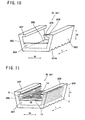
- the assembling device M shown in Figs 10 and 11 is formed entirely of an element holding member 201 made of flexible material such as rubber and resin, therefore, the element holding member 201 can be bent arbitrarily.
- the element holding member 201 is adapted to hold a plurality of elements 1 in the form of element array 1 in which the elements 1 are juxtaposed in its thickness direction and directed to open the recess 7 thereof.
- element holding member 201 comprises side walls 202 and 203 for restricting a lateral movement (in the direction represented by W in Figs. 10 and 11 ) of the element array 1 held therein by contacting with lateral faces 2 and 3 of the element array 1, and divider walls 204 and 205 for restricting a longitudinal movement (in the direction represented by L in Figs. 10 and 11 ) of the element array 1 held therein by contacting with a front or rear face of the element array 1.
- Both lateral ends of the divider walls 204 and 205 i.e., both right and left ends in Figs. 10 and 11
- a bottom portions i.e., lower portions in Figs 10 and 11
- bottom faces (i.e., lower end faces in Figs 10 and 11 ) of side walls 202 and 203 and the divider walls 204 and 205 are integrally fixed with a rectangular bottom plate 206. That is, the element holding member 201 is shaped into a container-like (or package-like) shape in which an upper face (i.e., an upper side in Figs. 10 and 11 ) thereof is opened.
- the element holding member 201 is capable of accommodating and holding the elements 1 in the form of element array 1 in the container-like inner space thereof.
- the element holding member 201 further comprises latch portions 207 and 208 on leading ends (i.e., upper ends in Figs. 10 and 11 ) of both side walls 202 and 203.
- the latch portions 207 and 208 contact to upper faces of both of the protruding portions 9 of the element array 1 held in the element holding member 201, thereby restricting vertical movement (in the direction represented by H in Figs 10 and 11 ) of the element array 1 to prevent disengagement of the element array 1 from the element holding member 201. Both lateral and vertical movements of the element array 1 held in the element holding member 201 are thus restricted so that the element array 1 can be held in the element holding member 201 stably.
- a plurality of slits 206a is formed on the bottom plate 206 in the width direction (as represented by W in Figs 10 and 11 ) of the bottom plate 206.
- the slits 206a are formed parallel to each other at even intervals, and a cross section thereof is V-shape or U-shape.
- the element holding member 201 can be bent easily in its length direction into a circle or an ark as shown in Fig. 13 . That is, the element holding member 201 can be bent in its length direction along the circumference of the ring 8 while directing the element array 1 held therein to open to the outer circumferential side.
- Figs. 14 and 15 illustrate a modified example of the assembling device M of the driving belt V
- the element holding members 201 are joined with one another across a slit 209 formed in each space between the adjoining element holding members 201.
- a total length of the joined element holding members 201 is determined to a predetermined length expressed by a formula: " ⁇ x D - ⁇ " provided that an inner diameter of the ring 8 is ⁇ D as shown in Fig. 15 . Therefore, the ring 8 can be fitted into the recess 7 of the elements 1 held in the element holding members 201 as many as possible simultaneously.
- the plurality of element 1 is held in the element holding members 201, i.e., in the assembling device M in the form of element array 1 in which the elements 1 are juxtapose in its thickness direction while being directed to open the recess 7 thereof, and both lateral and vertical movements of the element array 1 are restricted in the element holding members 201.
- the assembling device M is made of flexible material so that the assembling device M is capable of winding in its length direction to hold and release the element array 1.
- the ring 8 can be fitted into the recess 7 of the plurality of element array 1 simultaneously so that both lateral sides of the rings 8a and 8b can also be fitted into the clearance between the protruding portions 9 and the bottom 7a of the recess 7 of the plurality of the element 1 simultaneously, by bending the assembling device M holding the element arrays 1 therein along the circumference of the ring 8, and by fitting the ring 8 into the recess 7 of the element arrays 1 being held.
- the driving belt V can be assembled efficiently to improve productivity thereof.
- This first assembling and manufacturing example is an example of using the assembling device M of the driving belt V explained in the above-explained first example.
- the first ring 8a and the second ring 8b are overlapped in its entire length. Specifically, the first ring 8a is partially buckled and situated inside of the second ring 8b as shown in Fig. 20 . As a result, the first ring 8a and the second ring 8b are overlapped in its thickness direction as shown in Fig. 21 .
- the elements 1 are juxtaposed in its thickness direction, and the element array 1 thus formed is set on the locking groove 103 formed on the base face 101a of the base member 101 while directing the width direction of the elements 1 substantially perpendicular to the base face 101a.
- the overlapped first ring 8a and the second ring 8b are inserted into the recess 7 of the element array 1 held on the base face 101a.
- the outer lateral side of the first ring 8a is fitted into the clearance between one of the protruding portions 9 and the bottom 7a of the recess 7 of the elements 1.
- the upper lid 106 is mounted on the predetermined position of the base member 101 on which the element array 1 holding the rings 8a and 8b in its recess 7 is erected.
- both lateral faces 2 and 3 of the element array 1 are locked by the element locking groove 103 of the base member 101 and the element locking groove 109 of the upper lid 106, and the lateral movement of the first ring 8a whose outer lateral side is fitted in the inner circumferential side of one of the protruding portions 9 is restricted by the ring holding member 108 of the upper lid 106.
- the actuator 105 arranged in the base member 101 is actuated to move the ring pushing member 104 upwardly, i.e., in the direction to contact to the second ring 8b thereby pushing the second ring 8b toward the other protruding portion 9.
- the plurality of elements 1 is thus held in the form of the element array 1 in which the elements 1 are juxtaposed in its thickness direction, and the overlapped first and second rings 8a and 8b are accommodated in the recess 7 of the element 1.
- the outer lateral side of the first ring 8a situated inside of the second ring 8b is fitted into the clearance between one of the protruding portions 9 and the bottom 7a of the recess 7, and the first ring 8a is held immovably.
- the second ring 8b overlapped outside of the first ring 8a is pushed toward the other protruding portion 9 thereby fitting the outer lateral side of the second ring 8b into the clearance between other protruding portions 9 and the bottom 7a of the recess 7.
- the ring 8 is accommodated properly in the recess 7 of the element 1 and the assembly of the driving belt V is completed.
- the ring 8 can be fitted into the recess 7 of the plurality of elements 1 at the same time. That is, assembly and manufacture of the driving belt V can be carried out efficiently to improve productivity thereof.
- This second assembling and manufacturing example is an example of using the assembling device M of the driving belt V explained in the above-explained second example.
- the first ring 8a and the second ring 8b are overlapped in its entire length. Specifically, the first ring 8a is partially buckled and situated inside of the second ring 8b as shown in Fig. 20 . As a result, the first ring 8a and the second ring 8b are overlapped in its thickness direction as shown in Fig. 21 . Alternatively, the first ring 8a and the second ring 8b alleged parallel to each other are overlapped partially in its length direction.
- the plurality of elements 1 is held in the container-shaped element holding member 201 the upper side (i.e., upper side in Figs. 10 and 11 ) thereof is opened, in the form of element array 1 in which the elements 1 are juxtaposed in its thickness direction and directed to open the recess 7 thereof.
- both lateral and vertical movements of the element array 1 are restricted in the element holding member 201 so that the element array 1 can be held in the element holding member 201 stably.
- the element holding member 201 is entirely made of flexible material such as rubber and resin so that the element holding member 201 can be bent arbitrarily to hold and release the element array 1.
- a plurality of slits 206a is formed parallel to each other at even intervals on the bottom plate 206 in the width direction (as represented by W in Figs 10 and 11 ) of the bottom plate 206 as shown in Figs 10 to 13 , and a cross section of the slits 206a is V-shape or U-shape. Therefore, the element holding member 201 can be bent easily into an arc or into a circle in its length direction.
- the first ring 8a and the second ring 8b are inserted into the recess 7 of the element array 1 held in the element holding member 201 from the overlapped portion. Specifically, the outer lateral side of overlapped portion of the first ring 8a is fitted into the clearance between one of the protruding portions 9 and the bottom 7a of the recess 7.
- both of the outer lateral sides of the first ring 8a and the second ring 8b are fitted into the clearances between protruding portions 9 and the bottom 7a of the recess 7 of the element array 1, and assembly of the driving belt V is completed.
- the element array 1 holding the overlapped portion of the first ring 8a and the second ring 8b is moved along the length direction of the rings 8a and 8b to the portion where the rings 8a and 8b are aligned parallel to each other.
- both of the outer lateral sides of the first ring 8a and the second ring 8b are fitted into the clearances between protruding portions 9 and the bottom 7a of the recess 7 of the element array 1, and assembly of the driving belt V is completed.
- the plurality of elements 1 is thus held in the element holding member 201, i.e., in the assembling device M, in the form of element array 1 in which the elements 1 are juxtapose in its thickness direction while being directed to open to the recess 7 thereof, and both lateral and vertical movements of the element array 1 are restricted in the element holding members 201.
- the assembling device M is made of flexible material so that the assembling device M capable of winding in its length direction to hold and release the element array 1.
- the ring 8 can be fitted into the recess 7 of the plurality of element array 1 simultaneously so that both lateral sides of the rings 8a and 8b can also be fitted into the clearances between the protruding portions 9 and the bottom 7a of the recess 7 of the plurality of the element 1 simultaneously, by bending the assembling device M holding the element arrays 1 therein along the circumference of the ring 8 and fitting the ring 8 into the recess 7 of the element array 1 being held.
- the driving belt V can be assembled efficiently and productivity of the driving belt V is thereby improved.
- the plurality of element holding members 201 can be joined with one another across a slit 209 to form the assembling device M. Therefore, the ring 8 can be fitted into the recess 7 of the elements 1 as many as possible at the same time by using the assembling device M thus structured.
- This third assembling and manufacturing example is an example of using both of the assembling devices M of the above-explained second and third example.
- the ring 8 is fitted into the recess 7 of the most pieces (e.g., 80%) of the scheduled number of the elements 1 by the method of first assembling and manufacturing example using the assembling device M of the first example, or a predetermined device and method.
- the remaining portion of the ring 8 is fitted into the recess 7 of the remaining pieces of the elements 1 by the method of second assembling and manufacturing example using the assembling device M of the second example.
- the ring 8 can be fitted into the recess 7 of the plurality of elements 1 simultaneously and easily. Therefore, the driving belt V can be assembled efficiently in its entire length so that the productivity thereof can be improved.
- the present invention should not be limited to the aforementioned example. That is, although the examples of the present invention thus far describe relate to the driving belt used in a belt type continuously variable transmission, the present invention can also be applied to a driving belt to be applied to another kind of transmission mechanism composed mainly of a belt and pulleys.
Landscapes
- Engineering & Computer Science (AREA)
- General Engineering & Computer Science (AREA)
- Mechanical Engineering (AREA)
- Transmissions By Endless Flexible Members (AREA)
- Belt Conveyors (AREA)
- General Details Of Gearings (AREA)
Abstract
Description
- This invention relates to an assembling device, an assembling method and a manufacturing method of a driving belt, in which a plurality of plate elements interlinked with one another in a circular manner is fastened by an endless annular ring.
- In the prior art, a geared transmission capable of changing a gear stage thereof stepwise, and a continuously variable transmission capable of varying a speed change ratio steplessly are available as a transmission mechanism for transmitting power between rotary members. For example, a belt-type continuously variable transmission and a toroidal-type continuously variable transmission are known as the continuously variable transmission. Specifically, the belt-type continuously variable transmission is a transmission varying a speed change ratio continuously using a pair of drive pulleys and a pair of driven pulleys, and a driving belt applied to those pulleys. The known endless driving belt used in such belt-type continuously variable transmission is prepared by arranging a plurality of plate members called an "element" or a "block" in a circular manner while connecting the plate members with one another, and fastening the interlinked plate members by an annular belt called a "band" or a "carrier".
- When the driving belt of this kind applied to the drive and driven pulleys is driven by driving the drive pulley, a frictional force acts on a contact portion between the element and the drive pulley, and a compressive force is applied to the elements in the arranging direction thereof, i.e., in the thickness direction thereof according to a torque of the drive pulley. The compressive force applied to the element being contacted with the drive pulley is transmitted to the element being contacted with the driven pulley via the elements existing between the drive and driven pulleys. When the compressive force is transmitted to the element being contacted with the driven pulley, a frictional force is generated at the contact portion between the element and the driven pulley, and a torque to rotate the driven pulley is established according to the transmitted compressive force. The power is thus transmitted between the drive and driven pulley through the driving belt.
- One example of above-explained driving belt is disclosed in Japanese Patent Laid-Open No.
2000-249195 2000-249195 - In addition to above, Japanese Patent Laid-Open No.
2001-193796 2001-193796 - On the other hand, Japanese Patent Laid-Open No.
2000-205345 2000-205345 - According to the transmission belt taught by Japanese Patent Laid-Open No.
2000-249195 - According to the transmission belt of Japanese Patent Laid-Open No.
2000-249195 - In order to twist the carriers being arranged parallel to each other thereby overlapping those carriers partially, it is necessary to swing the interlinked elements, that is, to pivot the elements relatively with each other. However, according to the transmission belt taught by Japanese Patent Laid-Open No.
2000-249195 - In order to solve the above-mentioned problem, the applicant has filed an application relating to the driving belt, in which a male connection and a female connection for joining adjoining elements are individually formed on each face of the element being opposed to the adjoining element, at a center of width of the element. Therefore, each element can pivot relatively with the adjoining elements so that the two rows of rings aligned parallel to each other can be overlapped partially when fitted with the elements.
- However, the two rows of the rings have to be fitted into the recess of large number of element, for example, about 400 pieces of the elements. This means that it will take long time for assembling a driving belt by fitting the ring into the recess of the element piece by piece by hand, or fitting the ring into the recess of every several pieces of the element by hand. In addition to above, in case of assembling the driving belt manually by hand, a length of time to assemble the driving belt may be varied depending on the person. Thus, productivity of the driving belt still has to be improved by fitting the ring into the recess of the elements in a systematic manner.
- The present invention has been conceived noting the technical problems thus far described, and its object is to provide an assembling device, an assembling method and a manufacturing method of a driving belt capable of fitting the ring into the recess of the elements easily and efficiently to improve a productivity of the driving belt.
- In order to achieve the above-mentioned object, according to the present invention, there is provided an assembling device of a driving belt, in which a plurality of elements is interlinked annularly in a manner to situate a recess thereof to open to an outer circumferential side, and in which a first ring and a second ring are accommodated parallel to each other in the recess of the element, and held in an inner circumferential side of protruding portions formed on an opening end side of inner walls of the recess to prevent detachment of the rings, comprising: a ring holding mechanism immovably holding the first ring being fitted in an inner circumferential side of one of the protruding portions in the recess; and a ring moving mechanism for moving the second ring relatively to the first ring close toward other protruding portion.
- According to the invention, assembling device of a driving belt further comprises an element holding mechanism for holding a plurality of elements in a form of element array in which the elements are juxtaposed to each other in its thickness direction.
- In addition to above, the first ring is to be overlapped inside of the second ring and the second ring is to be overlapped outside of the first ring, when those rings are overlapped in its thickness direction by buckling one of the rings partially.
- According to another aspect of the present invention, there is provided an assembling device of a driving belt, in which a plurality of elements is interlinked annularly in a manner to situate a recess thereof to open to an outer circumferential side, and in which a first ring and a second ring are accommodated parallel to each other in the recess of the element, and held in an inner circumferential side of protruding portions formed on an opening end side of inner walls of the recess to prevent detachment of the rings, comprising: an element holding member for holding the plurality of elements in a form of an element array, in which the elements are juxtaposed in its thickness direction and directed to open the recess thereof.
- Specifically, the above-mentioned element holding member is made of a flexible material. That is, the element holding member is capable of winding into a circle or an arc in its length direction thereby holding and releasing the element array.
- In addition to above, the element holding member comprises side walls for restricting a lateral movement of the element array held therein by contacting with lateral faces of the element array, and divider walls for restricting a longitudinal movement of the element array held therein by contacting with a front face or a rear face of the element array.
- According to still another aspect of the present invention, there is provided an assembling method of a driving belt, in which a plurality of elements is interlinked annularly in a manner to situate a recess thereof to open to an outer circumferential side, and in which a first ring and a second ring are accommodated parallel to each other in the recess of the element, and held in an inner circumferential side of protruding portions formed on an opening end side of inner walls of the recess to prevent detachment of the rings, comprising: overlapping the first and second rings in its thickness direction by buckling one of the rings partially; holding the first ring overlapped inside of the second ring immovably while fitting the first ring in an inner circumferential side of one of the protruding portions in the recess; and thereafter fitting the second ring overlapped outside of the first ring in an inner circumferential side of other protruding portion in the recess by moving second ring toward other protruding portion.
- Specifically, when fitting the first ring into the inner circumferential side of one of the protruding portions, the plurality of elements are held in the form of element array in which the elements are juxtaposed in its thickness direction in advance.
- According to still another aspect of the present invention, there is provided an assembling method of a driving belt, in which a plurality of elements is interlinked annularly in a manner to situate a recess thereof to open to an outer circumferential side, and in which a first ring and a second ring are accommodated parallel to each other in the recess of the element, and held in an inner circumferential side of protruding portions formed on an opening end side of inner walls of the recess to prevent detachment of the rings, comprising: holding the plurality of elements in a form of an element array in which the elements are juxtaposed to each other in its thickness direction and directed to open the recess thereof; overlapping the first and the second rings in its thickness direction, or overlapping the first and the second rings in its thickness direction partially in its length direction, by buckling one of the rings partially; inserting the overlapped rings or an overlapped portion of the rings into the recess of the element array being held; fitting the first and second rings respectively in the inner circumferential side of the protruding portions in the recess, by fitting the first ring overlapped inside of the second ring in an inner circumferential side of one of the protruding portion, and fitting the second ring overlapped outside of the first ring in an inner circumferential side of the other protruding portion by moving the second ring close toward the other protruding portion, or by moving the element array accommodating the overlapped rings in its recess along the length direction of the rings to a portion where the first and the second rings are aligned parallel to each other; and thereafter releasing the plurality of elements being held in the form of the element array.
- According to the above-mentioned method of the invention, the element array is held by an element holding member made of a flexible material. That is, the element holding member is capable of winding into a circle or an arc in its length direction thereby holding and releasing the element array.
- The assembling method of a driving belt of the invention further comprising: holding the plurality of elements in the form of element array in which the elements are juxtaposed to each other in its thickness direction and directed to open the recess thereof; inserting a portion of the rings overlapped partially in its length direction into the recess of the element array being held; fitting the first and the second rings in an inner circumferential side of the protruding portions in the recess, by moving the element array accommodating the overlapped portion of the rings in its recess along the length direction of the rings to a portion where the first and the second rings are aligned parallel to each other, or by aligning the partially overlapped first and second rings to be parallel to each other in its entire length; and thereafter releasing the plurality of elements being held in the form of the element array.
- As explained above, the element array is held by an element holding member made of a flexible material. That is, the element holding member is capable of winding into a circle or an arc in its length direction thereby holding and releasing the element array.
- According to still another aspect of the present invention, there is provided a manufacturing method of a driving belt, in which a first ring and a second ring are accommodated parallel to each other in a recess of a plurality of elements, and in which the rings are held by protruding portions formed on an opening end side of inner walls of the recess to prevent detachment of the rings from the recess, comprising: arranging the plurality of elements annularly in a manner to situate the recess to open to an outer circumferential side; overlapping the first and the second rings in its thickness direction by buckling one of the rings partially; holding the first ring overlapped inside of the second ring immovably in the recess of the elements arranged annularly while fitting the first ring in an inner circumferential side of one of the protruding portion; and thereafter fitting the second ring overlapped outside of the first ring in an inner circumferential side of other protruding portion by moving the second ring close toward the other protruding portion.
- Specifically, when fitting the first ring into the inner circumferential side of one of the protruding portions, the plurality of elements is held in a form of element array in which the elements are juxtaposed in its thickness direction in advance.
- According to still another aspect of the present invention, there is provided a manufacturing method of a driving belt, in which a first ring and a second ring are accommodated parallel to each other in a recess of a plurality of elements, and in which the rings are held by protruding portions formed on an opening end side of inner walls of the recess to prevent detachment of the rings from the recess, comprising: holding the plurality of elements in a form of element array in which the elements are juxtaposed annularly to each other in its thickness direction in a manner to situate the recess to open to an outer circumferential side; overlapping the first and the second rings in its thickness direction, or overlapping the first and the second rings in its thickness direction partially in its length direction, by buckling one of the rings partially; inserting the overlapped rings or an overlapped portion of the rings into the recess of the element array being held; fitting the first and second rings respectively in the inner circumferential side of the protruding portions in the recess, by fitting the first ring overlapped inside of the second ring in an inner circumferential side of one of the protruding portion, and fitting the second ring overlapped outside of the first ring in an inner circumferential side of the other protruding portion by moving the second ring close toward the other protruding portion, or by moving the element array accommodating the overlapped rings in its recess along the length direction of the rings to a portion where the first and the second rings are aligned parallel to each other; and thereafter releasing the plurality of elements being held in the form of the element array.
- As explained above, the element array is held by an element holding member made of a flexible material. That is, the element holding member is capable of winding into a circle or an arc in its length direction thereby holding and releasing the element array.
- The manufacturing method of a driving belt of the invention further comprising: holding the plurality of elements in the form of element array in which the elements are juxtaposed to each other in its thickness direction and directed to open the recess thereof; inserting a portion of the rings overlapped partially in its length direction into the recess of the element array being held; fitting the first and the second rings in an inner circumferential side of the protruding portions in the recess, by moving the element array accommodating the overlapped portion of the rings in its recess along the length direction of the rings to a portion where the first and the second rings are aligned parallel to each other, or by aligning the partially overlapped first and second rings to be parallel to each other in its entire length; and thereafter releasing the plurality of elements being held in the form of the element array.
- As explained above, the element array is held by an element holding member made of a flexible material. That is, the element holding member is capable of winding into a circle or an arc in its length direction thereby holding and releasing the element array.
- According to the present invention, two rows of the rings such as the first and the second rings are thus accommodated in the recess of the plurality of elements. More specifically, the outer lateral side of the first ring is fitted into the clearance between one of the protruding portions and the bottom of the recess, and the first element is held immovably. On the other hand, the second ring is pushed relatively to the first ring, that is, pushed toward other protruding portion to be fitted into the clearance between the other protruding portion and the bottom of the recess. As a result, the two rows of rings are accommodated in the recess of the elements. Therefore, two rows of rings can be fitted into the recess of the plurality of the elements simultaneously. According to the present invention, therefore, the driving belt can be assembled efficiently, and the productivity of the driving belt is thereby improved.
- In addition to the above-mentioned advantage, the plurality of elements is held in the form of element array in which the elements are juxtaposed to each other in its thickness direction. That is, the two rows of rings can be fitted into the recess of the plurality of elements being held in the form of the element array simultaneously and easily.
- According to the invention, the first ring and the second ring are thus overlapped in its thickness direction by buckling the first ring partially to be overlapped inside of the second ring. Therefore, the two rows of rings can be fitted into the recess of the plurality of elements simultaneously and easily.
- Specifically, the plurality of elements is held in the form of an element array, in which the elements are juxtaposed in its thickness direction and directed to open the recess thereof. Therefore, the two rows of rings can be fitted into the recess of the plurality of the elements simultaneously while fitting those rings in the inner circumferential side of both of the protruding portions. As a result, the driving belt can be assembled efficiently and the productivity of the driving belt is thereby improved.
- As explained above, the plurality of elements is held in the form of element array by the element holding member made of a flexible material and capable of winding into a circle or an arc in its length direction. Therefore, the two rows of rings can be fitted into the recess of the plurality of elements being held in the form of the element array simultaneously and easily.
- In addition to the above-mentioned advantage, the element array is held properly by the side walls restricting a lateral movement of the elements and by the divider walls restricting a longitudinal movement of the elements. Therefore, the two rows of rings can be fitted into the recess of the plurality of elements simultaneously and easily.
- According to the invention, first of all, the first and second rings are overlapped in its thickness direction by buckling the first ring partially and situating the first ring inside of the second ring, and the overlapped rings are inserted into the recess of the elements. In the recess of the elements, the outer lateral side of the first ring is fitted in the inner circumferential side of one of the protruding portions and held immovably. Then, the second ring is pushed toward the other protruding portion to be fitted in the inner circumferential side of the other protruding portion. As a result, the two rows of rings are fitted properly in the recess of the element. Thus, the two rows of rings can be fitted into the recess of the plurality of elements simultaneously so that the driving belt can be assembled efficiently. Consequently, the productivity of the driving belt is improved.
- In addition to the above-mentioned advantage, the plurality of elements is held in the form of element array in which the elements are juxtaposed in its thickness direction in advance. Therefore, the two rows of rings can be fitted into the recess of the plurality of elements simultaneously and easily.
- According to the invention, the plurality of elements is held in the form of element array in which the elements are juxtaposed to each other in its thickness direction and directed to open the recess thereof. On the other hand, the first and the second rings are overlapped partially or entirely in its length direction, and the overlapped rings or the overlapped portion of the rings are inserted into the recess of the element array. Then, the first ring is fitted in the inner circumferential side of one of the protruding portions, and the second ring is fitted in the inner circumferential side of the other protruding portion by pushing second ring toward other protruding portion. Alternatively, the first and second rings are fitted in the inner circumferential side of both of the protruding portions by moving the element array accommodating the overlapped rings in its recess along the length direction of the rings to the portion where the first and the second rings are aligned parallel to each other. Thus, the two rows of rings can be fitted into the recess of the plurality of elements simultaneously so that the driving belt can be assembled efficiently Consequently, the productivity of the driving belt is improved.
- In addition to the above-mentioned advantage, the plurality of the elements is held in the form of element array by the member made of a flexible material capable of winding into a circle or an arc in its length direction thereby holding and releasing the element array. Therefore, the two rows of rings can be fitted into the recess of the plurality of elements simultaneously and easily.
- As explained above, the plurality of elements is held in the form of element array in which the elements are juxtaposed in its thickness direction and directed to open the recess thereof. After the two rows of the rings are fitted into the recess of the most pieces of scheduled number of the elements by the method specified in
claim - In addition to the above-mentioned advantage, after the two rows of the rings are fitted into the recess of the most pieces of scheduled number of the elements by the predetermined method, the elements to accommodate the remaining portion of the rings in its recess are held in the form of element array by the flexible member capable of winding into a circle or an arc in its length direction to hold and release the element array. Therefore, the two rows of rings can be fitted into the recess of the elements efficiently in almost entire length thereof, and the productivity of the driving belt is thereby improved.
-
-
Fig. 1 is a sectional view schematically showing a configuration of the assembling device of the driving belt according to the first example of the invention. -
Fig. 2 is a top view schematically showing a configuration of the assembling device of the driving belt according to the first example of the invention. -
Fig. 3 is a sectional view schematically showing a cross-section of the base member of the assembling device of the driving belt according to the first example of the invention (A-A section ofFig. 2 ). -
Fig. 4 is a top view schematically showing the assembling device of the driving belt according to the first example in which the base member is holding a plurality of elements. -
Fig. 5 is a sectional view schematically showing the assembling device of the driving belt according to the first example in which the base member is holding a plurality of elements (A-A section ofFig. 4 ). -
Fig. 6 is a top view schematically showing the assembling device of the driving belt according to the first example in which the base member is holding a plurality of elements and overlapped rings. -
Fig. 7 is a sectional view schematically showing the assembling device of the driving belt according to the first example in which the base member is holding a plurality of elements and overlapped rings (A-A section ofFig. 6 ). -
Fig. 8 is a sectional view schematically showing the assembling device of the driving belt according to the first example in which the base member is holding a plurality of elements and overlapped rings (B-B section ofFig. 6 ). -
Fig. 9 is a side-sectional view schematically showing the assembling device of the driving belt according to the first example which is fitting the ring into the recess of the element. -
Fig. 10 is a perspective view schematically showing the second example of the assembling device of the driving belt according to the invention. -
Fig. 11 is a perspective view schematically showing the assembling device of the driving belt according to the second example which is holding a plurality of elements. -
Fig. 12 is a side view schematically showing the assembling device of the second example. -
Fig. 13 is a side view schematically showing the assembling device of the second example bent in its length direction. -
Fig. 14 is a side view schematically showing a modified example of the assembling device of the driving belt according to the second example. -
Fig. 15 is a view schematically showing the two rows of rings constituting the driving belt of the invention. -
Fig. 16 is a front view schematically showing the driving belt to which the invention is applied. -
Fig. 17 is a side-sectional view partially showing an example of the driving belt to which the invention is applied. -
Fig. 18 is an explanatory drawing showing a pivotal movement of the elements of the driving belt to which the invention is applied. -
Fig. 19 is a view schematically showing an overlapped portion of the rings and a remaining portion of the rings aligned parallel to each other. -
Fig. 20 is a view schematically showing the rings overlapped by buckling one of the rings partially. -
Fig. 21 is a side view schematically showing the rings overlapped by buckling one of the rings partially shown inFig. 20 . - Next, this invention will be explained with reference to the accompanying drawings. A configuration of the driving belt to which the invention is applied will be explained first of all, and then, examples of the assembling device, assembling methods, and manufacturing methods of the driving belt are to be explained sequentially.
- First of all, a configuration of the driving belt to which the invention is applied will be explained with reference to
Figs. 16 and 17. Fig. 16 shows an example of a driving belt V to be applied to a drive pulley (i.e., an input shaft side pulley) and a driven pulley (i.e., an output shaft side pulley) of a belt type continuously variable transmission so as to transmit a power between those pulleys. Anelement 1 is a metal plate member comprising a base portion (or main body) 4. Both lateral faces 2 and 3 of thebase portion 4, that is, both lateral ends (in the direction of x-axis inFig. 16 ) of thebase portion 4 are inclined. The inclined lateral faces 2 and 3 are frictionally contacted with a V-shapedgroove 5a of a drive or drivenpulley 5 of the belt type continuously variable transmission to transmit a torque. - The
base portion 4 comprisescolumns 6 erected vertically (in the direction of y-axis inFigs. 16 and 17 ) at both lateral ends (in the direction of x-axis inFig. 16 ) thereof. Accordingly, arecess 7 is formed by an upper face (or a top edge) 4a of thebase portion 4 and bothinner walls 6a of thecolumns 6 facing to the center of thebase portion 4. Thus, therecess 7 opens upwardly, in other words, therecess 7 opens toward an outer circumference of the driving belt V - Specifically, the
recess 7 is a space for accommodating anendless ring 8 for fastening theelements 1 interlinked closely with one another in a circular manner. That is, theupper face 4a functions as asaddle face 4a onto which an inner circumferential face of thering 8 is fitted. - The
ring 8 is a layered ring made of metal comprising a plurality of annular belt-like layers overlapped in a circumferential direction. According to the first example, tworings recess 7. Here, a configuration, dimensions, material, strength and so on of therings - The
element 1 comprises protrudingportions 9. Each protrudingportion 9 is formed integrally with thecolumn 6 and protrudes toward a width center of thebase portion 4 from an outer circumferential side of thecolumns 6, that is, both end faces 9a of the protrudingportions 9 are faced inwardly to be opposed to each other. In other words, the protrudingportion 9 is formed on both opening ends of therecess 7 above lateral ends of thering inner walls 6a, and both of the protrudingportions 9 protrude toward a width center of the recess 7 (i.e., in the direction of x-axis inFig. 16 ). That is, a clearance between the end faces 9a is an opening width W1 of therecess 7. On the other hand, a width of therecess 7 atbottom portion 7a (i.e., theupper face 4a) side, specifically, a clearance between theinner walls 6a is wider than the opening width W1, and which is represented by W2. - The
elements 1 are interlinked with one another in a circular manner and fastened by thering 8. Theelements 1 thus fastened by thering 8 is applied to the drive and drivenpulleys 5. In case the driving belt V is applied to thepulleys 5, clearances between theelements 1 are narrowed gradually toward a rotational center of thepulleys 5 in a region where theelements 1 are contacted with thepulleys 5, and theelements 1 are eventually contacted with one another at its portion close to the rotational center of thepulley 5. For this reason, a thickness of theelement 1 has to be thinned at its lower portion, that is, at the portion close to the rotational center of thepulley 5, as illustrated inFigs. 16 and 17 . - According to the example shown in
Fig. 17 , one of the faces of thebase portion 4 i.e., the left face inFig. 17 is thinned gradually from a predetermined portion below thesaddle face 4a. In case the belt V is being applied to thepulleys 5, theelements 1 are contacted with the adjoiningelement 1 at the portion where the thickness thereof starts to be reduced, in the region where theelements 1 are contacted with thepulley 5, in other words, in a curving region of the belt V That is, an edge of a boundary of thickness functions as a rockingedge 10. - A
male connection 11 and afemale connection 12 are respectively formed on each face of thebase portion 4 being opposed to theadjoining element 1, at the center of width of theelement 1. Specifically, as shown inFig. 17 , themale connection 11 of circular truncated cone is formed on one of the faces of thebase portion 4 where the rockingedge 10 is formed. On the other hand, the bottomed cylindricalfemale connection 12 to which the adjoiningmale connection 11 is inserted loosely is formed on a face opposite to the face on which themale connection 11 is formed. Therefore, theelements 1 can be kept in line within a straight region of the belt V where theelement 1 is not being contacted with thepulley 5. - That is, a relative position of the
elements 1 within the straight region of the driving belt V can be determined in both vertical and horizontal directions inFig. 16 by joining the male andfemale connections - As explained above, the
element 1 comprises therecess 7 on its outer circumferential side of the driving belt V and the protrudingportions 9 protruding toward the width center of therecess 7 are formed on opening ends of both of the inner walls of thecolumns 6. Further, themale connection 11 protruding toward the adjoining element is formed on one of the faces of theelement 1 being opposed to theadjoining element 1, and thefemale connection 12 into which the male connection is inserted loosely is formed on the face of theelement 1 opposite to the face on which themale connection 11 is formed. More specifically, onemale connection 11 and onefemale connection 12 are respectively formed on each face of theelement 1 being opposed to theadjoining element 1, at the center of width of theelement 1. - Since only one
male connection 11 and onefemale connection 12 are formed on each face of theelement 1 being opposed to theadjoining element 1 at the width center of theelement 1, and those male andfemale connections female connection elements 1 interlinked in a circular manner can swing relatively with each other, in other words, theinterlinked elements 1 can pivot relatively with each other, as shown inFig. 18 . - As mentioned above, the
ring 8 comprises thefirst ring 8a and thesecond ring 8b. Therefore, as shown inFig. 19 , therings Fig. 19 ) while keeping the remaining portion of therings Fig. 19 ). - Specifically, as shown in
Figs 20 and 21 , thefirst ring 8a and thesecond ring 8b are overlapped in its thickness direction by buckling one of the rings (i.e., thefirst ring 8a inFig. 20 ) and situating the buckled ring inside of other ring (i.e., thesecond ring 8b inFig. 20 ). - As shown in
Fig. 16 , a width L1 of thering 8, i.e., a total width of thefirst ring 8a and thesecond ring 8b aligned parallel to each other is wider than the aforementioned opening width W1 but narrower than the width W2. However, as indicated by L2 inFig. 18 , the total width of thering 8 can be reduced narrower than the opening width W1 by overlapping thefirst ring 8a and thesecond ring 8b entirely or partially in its length direction. - More specifically, according to the
element 1 and thering 8 of the invention, the opening width W1 of therecess 7 is narrower than the width L1 of thering 8, and the width W2 of therecess 7 is wider than the width L1 of thering 8. In other words, the width L2 of therings recess 7, and the width L1 of therings recess 7 but narrower than the width W2 of therecess 7. - Therefore, the
ring 8 can be fitted into therecess 7 from the overlapped portion of thefirst ring 8a and thesecond ring 8b through the clearance between the end faces 9a. After the overlapped portion of thefirst ring 8a and thesecond ring 8b is thus fitted into therecess 7 from the clearance between the end faces 9a, theelement 1 is moved to the portion where thefirst ring 8a and thesecond ring 8b are aligned parallel to each other so that thefirst ring 8a and thesecond ring 8b can be fitted into the clearances between the protrudingportions 9 and the bottom 7a of therecess 7 shown in theFigs 16 and18 . Alternatively, it is also possible to align the overlapped rings 8a and 8b parallel to each other again in therecess 7. As a result, thefirst ring 8a and thesecond ring 8b can be held in therecess 7 while being aligned parallel to each other, and disengagement of thering 8 from theelement 1 is thereby prevented. - At an initial stage in which a number of the
elements 1 holding the rings is still relatively small, high degree of freedom of thefirst ring 8a and thesecond ring 8b is still ensured so that thoserings first ring 8a and thesecond ring 8b are held by theelements 1, a movement of therings - In order to solve the above-mentioned problem, according to the invention, the
elements 1 are interlinked to theadjoining elements 1 in a circular manner being pivotable relative to each other. Therefore, thering 8 can be twisted easily to be overlapped partially by a pivotal movement of theelement 1 even at a stage in which relatively large number ofelements 1 are holding thefirst ring 8a and thesecond ring 8b. - Here will be explained the first example of the assembling device M of the driving belt V with reference to the accompanying figures. As illustrated in
Fig. 1 , a plurality of elements (i.e., an element array) 1 is set on abase member 101, and one of the overlapped rings, i.e., thefirst ring 8a situated inside of thesecond ring 8b as shown inFigs 20 and 21 is fitted into the clearance between one of the protrudingportions 9 and the bottom 7a of therecess 7. On a base face (or an upper face) 101a of thebase member 101, column-shapedguide members 102 are fixedly erected substantially vertically. - More specifically, the
guide members 102 are erected on four corners of rectangular upper (or top) face of thebase member 101, as shown inFig. 2 . As also shown inFig. 2 ,element locking grooves 103 for holding the element array are formed on the upper face of thebase member 101. As illustrated inFig. 3 , theelement locking groove 103 comprises aninclined face 103a whose inclination is identical to that of the lateral faces 2 and 3 of theelement 1, and a cross-section thereof is a right triangle. That is, as a result of setting the plurality ofelements 1 on the lockinggroove 103 while directing the width direction of theelements 1 substantially perpendicular to thebase face 101a, theelement array 1 in which theelements 1 are juxtaposed in the thickness direction is erected substantially vertically on thebase face 101a, as shown inFigs. 4 and5 . - The
element locking grooves 103 are formed on the portions where an outer face of thering 8 overlapped inside of thering 8b is contacted closely to an inner face of thering 8b, except for regions where the overlappedring 8a is partially buckled as represented by P inFig. 20 and where after-mentionedring pushing members 104 are actuated. Accordingly, theelement array 1 can be erected on thebase member 101 in the direction in which the width direction of theelement 1 is substantially perpendicular to thebase face 101a, while accommodating theoverlapped ring 8a in the clearance between one of the protrudingportions 9 and thebase portion 7a of therecess 7, as shown inFigs. 6 ,7 and8 . - For example, as shown in
Fig. 2 , thering pushing member 104 for pushing an inner lateral side of thesecond ring 8b set on thebase member 101 toward the other protruding portion 9 (i.e., toward an upper side ofFig. 1 ), and anactuator 105 for actuating thering pushing member 104 in the direction vertical to thebase face 101a (i.e., the vertical direction inFig. 1 ) are arranged on both upper and lower width centers of thebase face 101a. - In addition to above, an
upper lid 106 is mounted on thebase member 101 through theguide members 102. Theupper lid 106 comprises guide holes 107 to which theguide members 102 are inserted to position theupper lid 106, andring holding members 108 for restricting a movement of thefirst ring 8a by contacting to an inner lateral side of thefirst ring 8a. - The guide holes 107 are also formed on the four corners of an
element holding face 106a of theupper lid 106 to insert theguide members 102 erected on thebase face 101a therein. Here, theupper lid 106 also compriseselement locking grooves 109 whose shape is identical to that of the lockinggroove 103. Specifically, theelement locking grooves 109 are formed on theelement holding face 106a of theupper lid 106 on the portion to be symmetrically faced with theelement locking grooves 103 when theupper lid 106 is mounted on theguide members 102. - The
ring holding members 108 are formed on the predetermined portions of theelement holding face 106a to contact to the inner lateral side of thefirst ring 8a when theupper lid 106 is appropriately mounted on thebase member 101 by inserting theguide members 102 into the guide holes 107. - Thus, the
element array 1 is set on theelement locking grooves 103, the overlapped rings 8a and 8b are accommodated in therecess 7 of theelements 1, and theupper lid 106 is positioned by inserting theguide members 102 into the guide holes 107. As a result, theelement array 1 is locked by both of the lockinggrooves first ring 8a whose outer lateral side is fitted into the clearance between one of the protrudingportions 9 and the bottom 7a of therecess 7 is held immovably. - As shown in
Fig. 9 , after mounting theupper lid 106 on the predetermined position of thebase member 101 and holding thefirst ring 8a immovably, theactuator 105 is actuated to move the pushingmember 104 upwardly inFig. 9 thereby pushing the inner lateral side of thesecond ring 8b. As a result, thesecond ring 8b is moved toward the other protrudingportion 9. - As explained above, the
upper lid 106 comprises thering holding member 108, and theupper lid 106 is mounted on thebase member 101 on which theelement array 1 accommodating the overlapped rings 8a and 8b in itsrecess 7 is locked by theelement locking groove 103. That is, theupper lid 106 and thering holding member 108 immovably hold the overlappedfirst ring 8a whose outer lateral side is fitted into the clearance between one of the protrudingportions 9 and the bottom 7a of therecess 7. Accordingly, theupper lid 106 and thering holding member 108 correspond to the ring holding mechanism of the invention. As also explained above, thering pushing member 104 is actuated by theactuator 105 to push the overlappedsecond ring 8b toward the other protrudingportion 9. That is, thering pushing member 104 and theactuator 105 correspond to the ring moving mechanism of the invention. Further, theelement locking groove 103 formed on thebase member 101, and theelement locking groove 109 formed on theupper lid 106 function to hold theelement array 1 in which theelements 1 are juxtaposed in its thickness direction. That is, theelement locking groove 103 and theelement locking groove 109 correspond to the element holding mechanism of the invention. - Thus, according to the assembling device M of the driving belt V thus far explained as the first example, the plurality of
elements 1 is held in the form ofelement array 1 in which the elements are juxtaposed in its thickness direction. Then, the overlappedring 8 is accommodated in therecess 7 of theelement 1. Specifically, thefirst ring 8a overlapped inside of thesecond ring 8b is fitted in the inner circumferential side of one of the protrudingportions 9 in therecess 7 and held immovably. Thereafter, thesecond ring 8b overlapped outside of thefirst ring 8a is pushed toward the other protrudingportion 9 relative to thefirst ring 8a held together with theelement array 1. As a result, thesecond ring 8b is fitted in the inner circumferential side of the other protrudingportion 9 in therecess 7, and the fitting work of fitting thering 8 into therecess 7 of theelement 1 is completed. Therefore, thering 8 can be fitted into the recess of the plurality of elements simultaneously so that the driving belt can be assembled efficiently. Consequently, the productivity of the driving belt is improved. - Here will be explained the second example of the assembling device M of the driving belt V with reference to the accompanying figures. The assembling device M shown in
Figs 10 and 11 is formed entirely of anelement holding member 201 made of flexible material such as rubber and resin, therefore, theelement holding member 201 can be bent arbitrarily. Specifically, theelement holding member 201 is adapted to hold a plurality ofelements 1 in the form ofelement array 1 in which theelements 1 are juxtaposed in its thickness direction and directed to open therecess 7 thereof. - Specifically,
element holding member 201 comprisesside walls Figs. 10 and 11 ) of theelement array 1 held therein by contacting with lateral faces 2 and 3 of theelement array 1, anddivider walls Figs. 10 and 11 ) of theelement array 1 held therein by contacting with a front or rear face of theelement array 1. Both lateral ends of thedivider walls 204 and 205 (i.e., both right and left ends inFigs. 10 and 11 ) and a bottom portions (i.e., lower portions inFigs 10 and 11 ) ofside walls Figs 10 and 11 ) ofside walls divider walls rectangular bottom plate 206. That is, theelement holding member 201 is shaped into a container-like (or package-like) shape in which an upper face (i.e., an upper side inFigs. 10 and 11 ) thereof is opened. - Therefore, the
element holding member 201 is capable of accommodating and holding theelements 1 in the form ofelement array 1 in the container-like inner space thereof. Theelement holding member 201 further compriseslatch portions Figs. 10 and 11 ) of bothside walls latch portions portions 9 of theelement array 1 held in theelement holding member 201, thereby restricting vertical movement (in the direction represented by H inFigs 10 and 11 ) of theelement array 1 to prevent disengagement of theelement array 1 from theelement holding member 201. Both lateral and vertical movements of theelement array 1 held in theelement holding member 201 are thus restricted so that theelement array 1 can be held in theelement holding member 201 stably. - As shown in
Figs 10 to 13 , a plurality of slits 206a is formed on thebottom plate 206 in the width direction (as represented by W inFigs 10 and 11 ) of thebottom plate 206. The slits 206a are formed parallel to each other at even intervals, and a cross section thereof is V-shape or U-shape. For this reason, theelement holding member 201 can be bent easily in its length direction into a circle or an ark as shown inFig. 13 . That is, theelement holding member 201 can be bent in its length direction along the circumference of thering 8 while directing theelement array 1 held therein to open to the outer circumferential side. -
Figs. 14 and15 illustrate a modified example of the assembling device M of the driving belt V As shown inFig. 14 , theelement holding members 201 are joined with one another across aslit 209 formed in each space between the adjoiningelement holding members 201. In order to set the assembling device M in the inner circumferential side of thering 8 by bending the joinedelement holding members 201, a total length of the joinedelement holding members 201 is determined to a predetermined length expressed by a formula: "π x D - α" provided that an inner diameter of thering 8 is φ D as shown inFig. 15 . Therefore, thering 8 can be fitted into therecess 7 of theelements 1 held in theelement holding members 201 as many as possible simultaneously. - Thus, according to the assembling device M of the second example, the plurality of
element 1 is held in theelement holding members 201, i.e., in the assembling device M in the form ofelement array 1 in which theelements 1 are juxtapose in its thickness direction while being directed to open therecess 7 thereof, and both lateral and vertical movements of theelement array 1 are restricted in theelement holding members 201. In addition, the assembling device M is made of flexible material so that the assembling device M is capable of winding in its length direction to hold and release theelement array 1. Therefore, thering 8 can be fitted into therecess 7 of the plurality ofelement array 1 simultaneously so that both lateral sides of therings portions 9 and the bottom 7a of therecess 7 of the plurality of theelement 1 simultaneously, by bending the assembling device M holding theelement arrays 1 therein along the circumference of thering 8, and by fitting thering 8 into therecess 7 of theelement arrays 1 being held. As a result, the driving belt V can be assembled efficiently to improve productivity thereof. - Here will be explained the first example of assembling and manufacturing the driving belt V of the invention with reference to the accompanying figures. This first assembling and manufacturing example is an example of using the assembling device M of the driving belt V explained in the above-explained first example.
- First of all, the
first ring 8a and thesecond ring 8b are overlapped in its entire length. Specifically, thefirst ring 8a is partially buckled and situated inside of thesecond ring 8b as shown inFig. 20 . As a result, thefirst ring 8a and thesecond ring 8b are overlapped in its thickness direction as shown inFig. 21 . - On the other hand, as shown in
Figs. 4 and5 , theelements 1 are juxtaposed in its thickness direction, and theelement array 1 thus formed is set on the lockinggroove 103 formed on thebase face 101a of thebase member 101 while directing the width direction of theelements 1 substantially perpendicular to thebase face 101a. - Then, the overlapped
first ring 8a and thesecond ring 8b are inserted into therecess 7 of theelement array 1 held on thebase face 101a. In this situation, the outer lateral side of thefirst ring 8a is fitted into the clearance between one of the protrudingportions 9 and the bottom 7a of therecess 7 of theelements 1. - Subsequently, the
upper lid 106 is mounted on the predetermined position of thebase member 101 on which theelement array 1 holding therings recess 7 is erected. As a result of mounting theupper lid 106 on thebase member 101, both lateral faces 2 and 3 of theelement array 1 are locked by theelement locking groove 103 of thebase member 101 and theelement locking groove 109 of theupper lid 106, and the lateral movement of thefirst ring 8a whose outer lateral side is fitted in the inner circumferential side of one of the protrudingportions 9 is restricted by thering holding member 108 of theupper lid 106. - After thus holding the
element array 1 and thefirst ring 8a, theactuator 105 arranged in thebase member 101 is actuated to move thering pushing member 104 upwardly, i.e., in the direction to contact to thesecond ring 8b thereby pushing thesecond ring 8b toward the other protrudingportion 9. - As the
ring pushing member 104 is further moved upwardly, thesecond ring 8b overlapped outside of thefirst ring 8a is gradually contacted with the other protrudingportion 9, and eventually fitted into the clearance between the other protrudingportion 9 and the bottom 7a of therecess 7, as shown inFig. 9 . As a result, both of the outer lateral sides of thefirst ring 8a and thesecond ring 8b are fitted into the clearances between the protrudingportions 9 and the bottom 7a of therecess 7 while being aligned parallel to each other, that is, an assembly of the driving belt V is completed. - According to the first assembling and manufacturing example of the driving belt V, the plurality of
elements 1 is thus held in the form of theelement array 1 in which theelements 1 are juxtaposed in its thickness direction, and the overlapped first andsecond rings recess 7 of theelement 1. In therecess 7, the outer lateral side of thefirst ring 8a situated inside of thesecond ring 8b is fitted into the clearance between one of the protrudingportions 9 and the bottom 7a of therecess 7, and thefirst ring 8a is held immovably. Then, thesecond ring 8b overlapped outside of thefirst ring 8a is pushed toward the other protrudingportion 9 thereby fitting the outer lateral side of thesecond ring 8b into the clearance between other protrudingportions 9 and the bottom 7a of therecess 7. As a result, thering 8 is accommodated properly in therecess 7 of theelement 1 and the assembly of the driving belt V is completed. Thus, thering 8 can be fitted into therecess 7 of the plurality ofelements 1 at the same time. That is, assembly and manufacture of the driving belt V can be carried out efficiently to improve productivity thereof. - Here will be explained the second example of assembling and manufacturing the driving belt V of the invention with reference to the accompanying figures. This second assembling and manufacturing example is an example of using the assembling device M of the driving belt V explained in the above-explained second example.
- First of all, the
first ring 8a and thesecond ring 8b are overlapped in its entire length. Specifically, thefirst ring 8a is partially buckled and situated inside of thesecond ring 8b as shown inFig. 20 . As a result, thefirst ring 8a and thesecond ring 8b are overlapped in its thickness direction as shown inFig. 21 . Alternatively, thefirst ring 8a and thesecond ring 8b alleged parallel to each other are overlapped partially in its length direction. - On the other hand, the plurality of
elements 1 is held in the container-shapedelement holding member 201 the upper side (i.e., upper side inFigs. 10 and 11 ) thereof is opened, in the form ofelement array 1 in which theelements 1 are juxtaposed in its thickness direction and directed to open therecess 7 thereof. As explained above, both lateral and vertical movements of theelement array 1 are restricted in theelement holding member 201 so that theelement array 1 can be held in theelement holding member 201 stably. - As also explained above, the
element holding member 201 is entirely made of flexible material such as rubber and resin so that theelement holding member 201 can be bent arbitrarily to hold and release theelement array 1. In addition, a plurality of slits 206a is formed parallel to each other at even intervals on thebottom plate 206 in the width direction (as represented by W inFigs 10 and 11 ) of thebottom plate 206 as shown inFigs 10 to 13 , and a cross section of the slits 206a is V-shape or U-shape. Therefore, theelement holding member 201 can be bent easily into an arc or into a circle in its length direction. - The
first ring 8a and thesecond ring 8b are inserted into therecess 7 of theelement array 1 held in theelement holding member 201 from the overlapped portion. Specifically, the outer lateral side of overlapped portion of thefirst ring 8a is fitted into the clearance between one of the protrudingportions 9 and the bottom 7a of therecess 7. - In case the
first ring 8a and thesecond ring 8b are overlapped entirely in its length direction, a predetermined external force is applied to thesecond ring 8b overlapped outside of thefirst ring 8a to push thesecond ring 8b toward the other protrudingportion 9. As a result, the outer lateral side of thesecond ring 8b is fitted into the clearance between the other protrudingportion 9 and the bottom 7a of therecess 7, and thefirst ring 8a and thesecond ring 8b are aligned parallel to each other. As a result, both of the outer lateral sides of thefirst ring 8a and thesecond ring 8b are fitted into the clearances between protrudingportions 9 and the bottom 7a of therecess 7 of theelement array 1, and assembly of the driving belt V is completed. - Alternatively, in case the
first ring 8a and thesecond ring 8b are overlapped partially in its length direction, theelement array 1 holding the overlapped portion of thefirst ring 8a and thesecond ring 8b is moved along the length direction of therings rings first ring 8a and thesecond ring 8b are fitted into the clearances between protrudingportions 9 and the bottom 7a of therecess 7 of theelement array 1, and assembly of the driving belt V is completed. - According to the second assembling and manufacturing example of the driving belt V, the plurality of
elements 1 is thus held in theelement holding member 201, i.e., in the assembling device M, in the form ofelement array 1 in which theelements 1 are juxtapose in its thickness direction while being directed to open to therecess 7 thereof, and both lateral and vertical movements of theelement array 1 are restricted in theelement holding members 201. In addition, the assembling device M is made of flexible material so that the assembling device M capable of winding in its length direction to hold and release theelement array 1. Therefore, thering 8 can be fitted into therecess 7 of the plurality ofelement array 1 simultaneously so that both lateral sides of therings portions 9 and the bottom 7a of therecess 7 of the plurality of theelement 1 simultaneously, by bending the assembling device M holding theelement arrays 1 therein along the circumference of thering 8 and fitting thering 8 into therecess 7 of theelement array 1 being held. As a result, the driving belt V can be assembled efficiently and productivity of the driving belt V is thereby improved. - Moreover, as shown in
Figs. 14 and15 , the plurality ofelement holding members 201 can be joined with one another across aslit 209 to form the assembling device M. Therefore, thering 8 can be fitted into therecess 7 of theelements 1 as many as possible at the same time by using the assembling device M thus structured. - Here will be explained the third example of assembling and manufacturing the driving belt V of the invention. This third assembling and manufacturing example is an example of using both of the assembling devices M of the above-explained second and third example.
- First of all, the
ring 8 is fitted into therecess 7 of the most pieces (e.g., 80%) of the scheduled number of theelements 1 by the method of first assembling and manufacturing example using the assembling device M of the first example, or a predetermined device and method. - Then, the remaining portion of the
ring 8 is fitted into therecess 7 of the remaining pieces of theelements 1 by the method of second assembling and manufacturing example using the assembling device M of the second example. - Thus, according to the third assembling and manufacturing example of the driving belt V the
ring 8 can be fitted into therecess 7 of the plurality ofelements 1 simultaneously and easily. Therefore, the driving belt V can be assembled efficiently in its entire length so that the productivity thereof can be improved. - Here, the present invention should not be limited to the aforementioned example. That is, although the examples of the present invention thus far describe relate to the driving belt used in a belt type continuously variable transmission, the present invention can also be applied to a driving belt to be applied to another kind of transmission mechanism composed mainly of a belt and pulleys.
Claims (18)
- An assembling device of a driving belt, in which a plurality of elements is interlinked annularly in a manner to situate a recess thereof to open to an outer circumferential side, and in which a first ring and a second ring are accommodated parallel to each other in the recess of the element, and held in an inner circumferential side of protruding portions formed on an opening end side of inner walls of the recess to prevent detachment of the rings, comprising:a ring holding mechanism immovably holding the first ring being fitted in an inner circumferential side of one of the protruding portions in the recess; anda ring moving mechanism for moving the second ring relatively to the first ring close toward other protruding portion.
- The assembling device of a driving belt as claimed in claim 1, further comprising:an element holding mechanism for holding a plurality of elements in a form of element array in which the elements are juxtaposed to each other in its thickness direction.
- The assembling device of a driving belt as claimed in claim 1 or 2, wherein:the first ring is to be overlapped inside of the second ring and the second ring is to be overlapped outside of the first ring, when those rings are overlapped in its thickness direction by buckling one of the rings partially.
- An assembling device of a driving belt, in which a plurality of elements is interlinked annularly in a manner to situate a recess thereof to open to an outer circumferential side, and in which a first ring and a second ring are accommodated parallel to each other in the recess of the element, and held in an inner circumferential side of protruding portions formed on an opening end side of inner walls of the recess to prevent detachment of the rings, comprising:an element holding member for holding the plurality of elements in a form of an element array, in which the elements are juxtaposed in its thickness direction and directed to open the recess thereof.
- The assembling device of a driving belt as claimed in claim 4, wherein:the element holding member is made of a flexible material so that it is capable of winding into a circle or into an arc in its length direction thereby holding and releasing the element array.
- The assembling device of a driving belt as claimed in claim 4 or 5, wherein the element holding member comprises:side walls for restricting a lateral movement of the element array held therein by contacting with lateral faces of the element array; anddivider walls for restricting a longitudinal movement of the element array held therein by contacting with a front face or a rear face of the element array.
- An assembling method of a driving belt, in which a plurality of elements is interlinked annularly in a manner to situate a recess thereof to open to an outer circumferential side, and in which a first ring and a second ring are accommodated parallel to each other in the recess of the element, and held in an inner circumferential side of protruding portions formed on an opening end side of inner walls of the recess to prevent detachment of the rings, comprising:overlapping the first and second rings in its thickness direction by buckling one of the rings partially;holding the first ring overlapped inside of the second ring immovably while fitting the first ring in an inner circumferential side of one of the protruding portions in the recess; andthereafter fitting the second ring overlapped outside of the first ring in an inner circumferential side of other protruding portion in the recess by moving second ring close toward the other protruding portion.
- The assembling method of a driving belt as claimed in claim 7, wherein:the plurality of elements are held in the form of element array in which the elements are juxtaposed in its thickness direction in advance when fitting the first ring into the inner circumferential side of one of the protruding portions.
- An assembling method of a driving belt, in which a plurality of elements is interlinked annularly in a manner to situate a recess thereof to open to an outer circumferential side, and in which a first ring and a second ring are accommodated parallel to each other in the recess of the element, and held in an inner circumferential side of protruding portions formed on an opening end side of inner walls of the recess to prevent detachment of the rings, comprising:holding the plurality of elements in a form of an element array in which the elements are juxtaposed to each other in its thickness direction and directed to open the recess thereof;overlapping the first and the second rings in its thickness direction, or overlapping the first and the second rings in its thickness direction partially in its length direction, by buckling one of the rings partially;inserting the overlapped rings or an overlapped portion of the rings into the recess of the element array being held;fitting the first and second rings respectively in the inner circumferential side of the protruding portions in the recess
by fitting the first ring overlapped inside of the second ring in an inner circumferential side of one of the protruding portion, and fitting the second ring overlapped outside of the first ring in an inner circumferential side of the other protruding portion by moving the second ring close toward the other protruding portion, or
by moving the element array accommodating the overlapped rings in its recess along the length direction of the rings to a portion where the first and the second rings are aligned parallel to each other; andthereafter releasing the plurality of elements being held in the form of the element array. - The assembling method of a driving belt as claimed in claim 9, wherein:the element array is held in an element holding member made of a flexible material so that it is capable of winding into a circle or into an arc in its length direction thereby holding and releasing the element array.
- The assembling method of a driving belt as claimed in claim 7 or 8, further comprising:holding the plurality of elements in the form of element array in which the elements are juxtaposed to each other in its thickness direction and directed to open the recess thereof;inserting a portion of the rings overlapped partially in its length direction into the recess of the element array being held;fitting the first and the second rings in an inner circumferential side of the protruding portions in the recess, by moving the element array accommodating the overlapped portion of the rings in its recess along the length direction of the rings to a portion where the first and the second rings are aligned parallel to each other, or by aligning the partially overlapped first and second rings to be parallel to each other in its entire length; andthereafter releasing the plurality of elements being held in the form of the element array.
- The assembling method of a driving belt as claimed in claim 11, wherein:the element array is held in an element holding member made of a flexible material so that it is capable of winding into a circle or into an arc in its length direction thereby holding and releasing the element array.
- A manufacturing method of a driving belt, in which a first ring and a second ring are accommodated parallel to each other in a recess of a plurality of elements, and in which the rings are held by protruding portions formed on an opening end side of inner walls of the recess to prevent detachment of the rings from the recess, comprising:arranging the plurality of elements annularly in a manner to situate the recess to open to an outer circumferential side;overlapping the first and the second rings in its thickness direction by buckling one of the rings partially;holding the first ring overlapped inside of the second ring immovably in the recess of the elements arranged annularly while fitting the first ring in an inner circumferential side of one of the protruding portion; andthereafter fitting the second ring overlapped outside of the first ring in an inner circumferential side of other protruding portion by moving the second ring close toward the other protruding portion.
- The manufacturing method of a driving belt as claimed in claim 13, wherein:the plurality of elements are held in the form of element array in which the elements are juxtaposed in its thickness direction in advance when fitting the first ring into the inner circumferential side of one of the protruding portions.
- A manufacturing method of a driving belt, in which a first ring and a second ring are accommodated parallel to each other in a recess of a plurality of elements, and in which the rings are held by protruding portions formed on an opening end side of inner walls of the recess to prevent detachment of the rings from the recess, comprising:holding the plurality of elements in a form of element array in which the elements are juxtaposed annularly to each other in its thickness direction in a manner to situate the recess to open to an outer circumferential side;overlapping the first and the second rings in its thickness direction, or overlapping the first and the second rings in its thickness direction partially in its length direction, by buckling one of the rings partially;inserting the overlapped rings or an overlapped portion of the rings into the recess of the element array being held;fitting the first and second rings respectively in the inner circumferential side of the protruding portions in the recess
by fitting the first ring overlapped inside of the second ring in an inner circumferential side of one of the protruding portion, and fitting the second ring overlapped outside of the first ring in an inner circumferential side of the other protruding portion by moving the second ring close toward the other protruding portion, or
by moving the element array accommodating the overlapped rings in its recess along the length direction of the rings to a portion where the first and the second rings are aligned parallel to each other; andthereafter releasing the plurality of elements being held in the form of the element array. - The manufacturing method of a driving belt as claimed in claim 15, wherein
the element array is held in an element holding member made of a flexible material so that it is capable of winding into a circle or into an arc in its length direction thereby holding and releasing the element array. - The manufacturing method of a driving belt as claimed in claim 15 or 16, further comprising:holding the plurality of elements in the form of element array in which the elements are juxtaposed to each other in its thickness direction and directed to open the recess thereof;inserting a portion of the rings overlapped partially in its length direction into the recess of the element array being held;fitting the first and the second rings in an inner circumferential side of the protruding portions in the recess, by moving the element array accommodating the overlapped portion of the rings in its recess along the length direction of the rings to a portion where the first and the second rings are aligned parallel to each other, or by aligning the partially overlapped first and second rings to be parallel to each other in its entire length; andthereafter releasing the plurality of elements being held in the form of the element array.
- The manufacturing method of a driving belt as claimed in claim 17, wherein:the element array is held in an element holding member made of a flexible material so that it is capable of winding into a circle or an arc in its length direction thereby holding and releasing the element array.
Priority Applications (1)
| Application Number | Priority Date | Filing Date | Title |
|---|---|---|---|
| EP11163115A EP2341263B1 (en) | 2006-08-28 | 2007-08-22 | Assembling device and assembling method for a power transmission belt |
Applications Claiming Priority (2)
| Application Number | Priority Date | Filing Date | Title |
|---|---|---|---|
| JP2006231272A JP4412310B2 (en) | 2006-08-28 | 2006-08-28 | Transmission belt assembling apparatus, assembling method and manufacturing method |
| PCT/JP2007/066698 WO2008026611A1 (en) | 2006-08-28 | 2007-08-22 | Assembling device, assembling method, and production method for power transmission belt |
Related Child Applications (1)
| Application Number | Title | Priority Date | Filing Date |
|---|---|---|---|
| EP11163115.6 Division-Into | 2011-04-20 |
Publications (3)
| Publication Number | Publication Date |
|---|---|
| EP2058553A1 true EP2058553A1 (en) | 2009-05-13 |
| EP2058553A4 EP2058553A4 (en) | 2011-01-05 |
| EP2058553B1 EP2058553B1 (en) | 2012-05-16 |
Family
ID=39135893
Family Applications (2)
| Application Number | Title | Priority Date | Filing Date |
|---|---|---|---|
| EP07806175A Not-in-force EP2058553B1 (en) | 2006-08-28 | 2007-08-22 | Assembling device and assembling method for a power transmission belt |
| EP11163115A Not-in-force EP2341263B1 (en) | 2006-08-28 | 2007-08-22 | Assembling device and assembling method for a power transmission belt |
Family Applications After (1)
| Application Number | Title | Priority Date | Filing Date |
|---|---|---|---|
| EP11163115A Not-in-force EP2341263B1 (en) | 2006-08-28 | 2007-08-22 | Assembling device and assembling method for a power transmission belt |
Country Status (9)
| Country | Link |
|---|---|
| US (1) | US20100011560A1 (en) |
| EP (2) | EP2058553B1 (en) |
| JP (1) | JP4412310B2 (en) |
| KR (1) | KR101026973B1 (en) |
| CN (1) | CN101512183B (en) |
| BR (1) | BRPI0716264A2 (en) |
| ES (1) | ES2385610T3 (en) |
| RU (1) | RU2395019C1 (en) |
| WO (1) | WO2008026611A1 (en) |
Cited By (3)
| Publication number | Priority date | Publication date | Assignee | Title |
|---|---|---|---|---|
| EP2341263A1 (en) | 2006-08-28 | 2011-07-06 | Toyota Jidosha Kabushiki Kaisha | Assembling device and assembling method for a power transmission belt |
| NL1039905C2 (en) * | 2012-11-20 | 2014-05-21 | Bosch Gmbh Robert | Drive belt and method for manufacturing a drive belt. |
| NL1039904C2 (en) * | 2012-11-20 | 2014-05-21 | Bosch Gmbh Robert | Drive belt and method for manufacturing a drive belt. |
Families Citing this family (2)
| Publication number | Priority date | Publication date | Assignee | Title |
|---|---|---|---|---|
| JP5969434B2 (en) * | 2013-07-17 | 2016-08-17 | トヨタ自動車株式会社 | Element array device and element array method |
| JP6929147B2 (en) * | 2017-06-29 | 2021-09-01 | キヤノン株式会社 | Image processing device, its control method, and program |
Family Cites Families (16)
| Publication number | Priority date | Publication date | Assignee | Title |
|---|---|---|---|---|
| NL152969C (en) * | 1973-08-31 | 1983-04-18 | Volvo Car Bv | DRIVING BELT WITH A TRAPEZIUM-SHAPED PROFILE, CONSISTING OF A METAL DRAWBAND AND SLIDABLE METAL CROSS-ELEMENTS. |
| JPS5922344U (en) * | 1982-08-02 | 1984-02-10 | トヨタ自動車株式会社 | Drive belt assembly device |
| NL8400213A (en) * | 1984-01-24 | 1985-08-16 | Doornes Transmissie Bv | DRIVE BELT FOR APPLICATION TO V-SHAPED PULLEYS. |
| NL8700122A (en) * | 1987-01-20 | 1988-08-16 | Doornes Transmissie Bv | METHOD FOR ASSEMBLING METAL DRIVE BELTS AND ASSEMBLY DEVICE |
| JPH0276941A (en) * | 1988-09-12 | 1990-03-16 | Nhk Spring Co Ltd | Power transmission belt and production thereof |
| US5047937A (en) * | 1990-06-01 | 1991-09-10 | General Motors Corporation | Engine CVT control system |
| JP3111186B1 (en) | 1998-11-05 | 2000-11-20 | 福寿工業株式会社 | Metal belt element and metal belt |
| JP3525784B2 (en) | 1999-01-21 | 2004-05-10 | 日産自動車株式会社 | Method and apparatus for assembling CVT belt |
| JP3525785B2 (en) | 1999-01-21 | 2004-05-10 | 日産自動車株式会社 | Method and apparatus for assembling CVT belt |
| JP2000249195A (en) | 1999-02-26 | 2000-09-12 | Mitsuboshi Belting Ltd | High-loaded transmission belt |
| JP3604605B2 (en) * | 1999-11-16 | 2004-12-22 | 本田技研工業株式会社 | Method and apparatus for assembling belt for continuously variable transmission |
| DE10056577A1 (en) * | 2000-11-15 | 2002-08-29 | Zf Batavia Llc | Device for mounting a push link belt |
| JP3755413B2 (en) * | 2001-03-19 | 2006-03-15 | トヨタ自動車株式会社 | Belt device and manufacturing method thereof |
| JP4039617B2 (en) * | 2002-08-09 | 2008-01-30 | 本田技研工業株式会社 | Ring mounting method and mounting device |
| CN1266400C (en) * | 2003-11-26 | 2006-07-26 | 程乃士 | Dry-type recombination type metal strip assembly for infinitely variable transmission |
| JP4412310B2 (en) | 2006-08-28 | 2010-02-10 | トヨタ自動車株式会社 | Transmission belt assembling apparatus, assembling method and manufacturing method |
-
2006
- 2006-08-28 JP JP2006231272A patent/JP4412310B2/en not_active Expired - Fee Related
-
2007
- 2007-08-22 EP EP07806175A patent/EP2058553B1/en not_active Not-in-force
- 2007-08-22 RU RU2009111221/11A patent/RU2395019C1/en not_active IP Right Cessation
- 2007-08-22 US US12/439,175 patent/US20100011560A1/en not_active Abandoned
- 2007-08-22 BR BRPI0716264-2A patent/BRPI0716264A2/en not_active IP Right Cessation
- 2007-08-22 WO PCT/JP2007/066698 patent/WO2008026611A1/en not_active Ceased
- 2007-08-22 EP EP11163115A patent/EP2341263B1/en not_active Not-in-force
- 2007-08-22 KR KR1020097004050A patent/KR101026973B1/en not_active Expired - Fee Related
- 2007-08-22 CN CN2007800321157A patent/CN101512183B/en not_active Expired - Fee Related
- 2007-08-22 ES ES07806175T patent/ES2385610T3/en active Active
Cited By (6)
| Publication number | Priority date | Publication date | Assignee | Title |
|---|---|---|---|---|
| EP2341263A1 (en) | 2006-08-28 | 2011-07-06 | Toyota Jidosha Kabushiki Kaisha | Assembling device and assembling method for a power transmission belt |
| NL1039905C2 (en) * | 2012-11-20 | 2014-05-21 | Bosch Gmbh Robert | Drive belt and method for manufacturing a drive belt. |
| NL1039904C2 (en) * | 2012-11-20 | 2014-05-21 | Bosch Gmbh Robert | Drive belt and method for manufacturing a drive belt. |
| WO2014080289A1 (en) * | 2012-11-20 | 2014-05-30 | Robert Bosch Gmbh | Drive belt and method for manufacturing a drive belt |
| WO2014080288A1 (en) * | 2012-11-20 | 2014-05-30 | Robert Bosch Gmbh | Drive belt and method for manufacturing a drive belt |
| CN104813065A (en) * | 2012-11-20 | 2015-07-29 | 罗伯特·博世有限公司 | Drive belt and method for manufacturing a drive belt |
Also Published As
| Publication number | Publication date |
|---|---|
| RU2395019C1 (en) | 2010-07-20 |
| ES2385610T3 (en) | 2012-07-27 |
| KR101026973B1 (en) | 2011-04-11 |
| US20100011560A1 (en) | 2010-01-21 |
| WO2008026611A1 (en) | 2008-03-06 |
| EP2341263A1 (en) | 2011-07-06 |
| EP2058553A4 (en) | 2011-01-05 |
| BRPI0716264A2 (en) | 2013-08-06 |
| CN101512183A (en) | 2009-08-19 |
| EP2058553B1 (en) | 2012-05-16 |
| JP4412310B2 (en) | 2010-02-10 |
| EP2341263B1 (en) | 2012-11-21 |
| CN101512183B (en) | 2010-10-27 |
| JP2008051326A (en) | 2008-03-06 |
| KR20090035614A (en) | 2009-04-09 |
Similar Documents
| Publication | Publication Date | Title |
|---|---|---|
| US8337347B2 (en) | Driving belt, and device and method for assembling same | |
| US8109851B2 (en) | Driving belt and method for assembling same | |
| EP2058554A1 (en) | Power transmission belt, device and method of assembling power transmission belt, and method of producing power transmission belt | |
| EP2058555A1 (en) | Power transmission belt and method of assembling the same | |
| EP2233781A1 (en) | Belt element and transmission belt | |
| EP2341263B1 (en) | Assembling device and assembling method for a power transmission belt | |
| US20110237376A1 (en) | Push type driving belt | |
| US20190101186A1 (en) | Driving belt and manufacturing method thereof | |
| WO2010103656A1 (en) | V-belt | |
| JPS636245A (en) | V-type chain belt for power transmission | |
| KR20010012017A (en) | Transmission | |
| JPH06300088A (en) | Chain belt | |
| EP2246589A1 (en) | Jig for assembling belt and method for assembling belt and method for producing belt | |
| JP2009204151A (en) | Endless metal belt, and its manufacturing method | |
| JP2010007860A (en) | Transmission belt assembling device, assembling method, and manufacturing method | |
| JP2012017829A (en) | Transmission belt |
Legal Events
| Date | Code | Title | Description |
|---|---|---|---|
| PUAI | Public reference made under article 153(3) epc to a published international application that has entered the european phase |
Free format text: ORIGINAL CODE: 0009012 |
|
| 17P | Request for examination filed |
Effective date: 20090226 |
|
| AK | Designated contracting states |
Kind code of ref document: A1 Designated state(s): AT BE BG CH CY CZ DE DK EE ES FI FR GB GR HU IE IS IT LI LT LU LV MC MT NL PL PT RO SE SI SK TR |
|
| AX | Request for extension of the european patent |
Extension state: AL BA HR MK RS |
|
| RBV | Designated contracting states (corrected) |
Designated state(s): DE ES FR GB IT NL |
|
| A4 | Supplementary search report drawn up and despatched |
Effective date: 20101203 |
|
| DAX | Request for extension of the european patent (deleted) | ||
| 17Q | First examination report despatched |
Effective date: 20110530 |
|
| GRAP | Despatch of communication of intention to grant a patent |
Free format text: ORIGINAL CODE: EPIDOSNIGR1 |
|
| RTI1 | Title (correction) |
Free format text: ASSEMBLING DEVICE AND ASSEMBLING METHOD FOR A POWER TRANSMISSION BELT |
|
| GRAS | Grant fee paid |
Free format text: ORIGINAL CODE: EPIDOSNIGR3 |
|
| GRAA | (expected) grant |
Free format text: ORIGINAL CODE: 0009210 |
|
| AK | Designated contracting states |
Kind code of ref document: B1 Designated state(s): DE ES FR GB IT NL |
|
| REG | Reference to a national code |
Ref country code: GB Ref legal event code: FG4D |
|
| REG | Reference to a national code |
Ref country code: DE Ref legal event code: R096 Ref document number: 602007022731 Country of ref document: DE Effective date: 20120726 |
|
| REG | Reference to a national code |
Ref country code: ES Ref legal event code: FG2A Ref document number: 2385610 Country of ref document: ES Kind code of ref document: T3 Effective date: 20120727 |
|
| REG | Reference to a national code |
Ref country code: NL Ref legal event code: T3 |
|
| PGFP | Annual fee paid to national office [announced via postgrant information from national office to epo] |
Ref country code: GB Payment date: 20120822 Year of fee payment: 6 |
|
| PGFP | Annual fee paid to national office [announced via postgrant information from national office to epo] |
Ref country code: ES Payment date: 20120827 Year of fee payment: 6 Ref country code: DE Payment date: 20120816 Year of fee payment: 6 Ref country code: IT Payment date: 20120810 Year of fee payment: 6 Ref country code: FR Payment date: 20120823 Year of fee payment: 6 |
|
| PGFP | Annual fee paid to national office [announced via postgrant information from national office to epo] |
Ref country code: NL Payment date: 20120816 Year of fee payment: 6 |
|
| RAP2 | Party data changed (patent owner data changed or rights of a patent transferred) |
Owner name: TOYOTA JIDOSHA KABUSHIKI KAISHA |
|
| PLBE | No opposition filed within time limit |
Free format text: ORIGINAL CODE: 0009261 |
|
| STAA | Information on the status of an ep patent application or granted ep patent |
Free format text: STATUS: NO OPPOSITION FILED WITHIN TIME LIMIT |
|
| 26N | No opposition filed |
Effective date: 20130219 |
|
| REG | Reference to a national code |
Ref country code: DE Ref legal event code: R084 Ref document number: 602007022731 Country of ref document: DE |
|
| REG | Reference to a national code |
Ref country code: GB Ref legal event code: 746 Effective date: 20130520 |
|
| REG | Reference to a national code |
Ref country code: DE Ref legal event code: R097 Ref document number: 602007022731 Country of ref document: DE Effective date: 20130219 |
|
| REG | Reference to a national code |
Ref country code: DE Ref legal event code: R084 Ref document number: 602007022731 Country of ref document: DE Effective date: 20130522 |
|
| REG | Reference to a national code |
Ref country code: NL Ref legal event code: V1 Effective date: 20140301 |
|
| GBPC | Gb: european patent ceased through non-payment of renewal fee |
Effective date: 20130822 |
|
| PG25 | Lapsed in a contracting state [announced via postgrant information from national office to epo] |
Ref country code: NL Free format text: LAPSE BECAUSE OF NON-PAYMENT OF DUE FEES Effective date: 20140301 Ref country code: DE Free format text: LAPSE BECAUSE OF NON-PAYMENT OF DUE FEES Effective date: 20140301 |
|
| REG | Reference to a national code |
Ref country code: DE Ref legal event code: R119 Ref document number: 602007022731 Country of ref document: DE Effective date: 20140301 |
|
| REG | Reference to a national code |
Ref country code: FR Ref legal event code: ST Effective date: 20140430 |
|
| PG25 | Lapsed in a contracting state [announced via postgrant information from national office to epo] |
Ref country code: IT Free format text: LAPSE BECAUSE OF NON-PAYMENT OF DUE FEES Effective date: 20130822 |
|
| PG25 | Lapsed in a contracting state [announced via postgrant information from national office to epo] |
Ref country code: GB Free format text: LAPSE BECAUSE OF NON-PAYMENT OF DUE FEES Effective date: 20130822 |
|
| PG25 | Lapsed in a contracting state [announced via postgrant information from national office to epo] |
Ref country code: FR Free format text: LAPSE BECAUSE OF NON-PAYMENT OF DUE FEES Effective date: 20130902 |
|
| PG25 | Lapsed in a contracting state [announced via postgrant information from national office to epo] |
Ref country code: ES Free format text: LAPSE BECAUSE OF NON-PAYMENT OF DUE FEES Effective date: 20130823 |