EP2058263B1 - Drive system for moving walkways and escalators - Google Patents
Drive system for moving walkways and escalators Download PDFInfo
- Publication number
- EP2058263B1 EP2058263B1 EP08380207A EP08380207A EP2058263B1 EP 2058263 B1 EP2058263 B1 EP 2058263B1 EP 08380207 A EP08380207 A EP 08380207A EP 08380207 A EP08380207 A EP 08380207A EP 2058263 B1 EP2058263 B1 EP 2058263B1
- Authority
- EP
- European Patent Office
- Prior art keywords
- drive
- plates
- chains
- stairs
- steps
- Prior art date
- Legal status (The legal status is an assumption and is not a legal conclusion. Google has not performed a legal analysis and makes no representation as to the accuracy of the status listed.)
- Not-in-force
Links
- 239000003638 chemical reducing agent Substances 0.000 claims description 8
- 230000007246 mechanism Effects 0.000 claims description 6
- 230000000295 complement effect Effects 0.000 claims description 4
- 230000001360 synchronised effect Effects 0.000 claims description 4
- 230000000149 penetrating effect Effects 0.000 claims 1
- 239000000463 material Substances 0.000 description 10
- 239000011248 coating agent Substances 0.000 description 4
- 238000000576 coating method Methods 0.000 description 4
- 239000002184 metal Substances 0.000 description 3
- 239000012858 resilient material Substances 0.000 description 3
- 230000000694 effects Effects 0.000 description 2
- 230000007704 transition Effects 0.000 description 2
- 230000009471 action Effects 0.000 description 1
- 230000005540 biological transmission Effects 0.000 description 1
- 230000008878 coupling Effects 0.000 description 1
- 238000010168 coupling process Methods 0.000 description 1
- 238000005859 coupling reaction Methods 0.000 description 1
- 229920001971 elastomer Polymers 0.000 description 1
- 239000000806 elastomer Substances 0.000 description 1
- 238000004519 manufacturing process Methods 0.000 description 1
- 229920002635 polyurethane Polymers 0.000 description 1
- 239000004814 polyurethane Substances 0.000 description 1
- 238000005096 rolling process Methods 0.000 description 1
Images


Classifications
-
- B—PERFORMING OPERATIONS; TRANSPORTING
- B66—HOISTING; LIFTING; HAULING
- B66B—ELEVATORS; ESCALATORS OR MOVING WALKWAYS
- B66B23/00—Component parts of escalators or moving walkways
- B66B23/02—Driving gear
- B66B23/028—Driving gear with separate drive chain or belt that engages directly the carrying surface chain
-
- B—PERFORMING OPERATIONS; TRANSPORTING
- B65—CONVEYING; PACKING; STORING; HANDLING THIN OR FILAMENTARY MATERIAL
- B65G—TRANSPORT OR STORAGE DEVICES, e.g. CONVEYORS FOR LOADING OR TIPPING, SHOP CONVEYOR SYSTEMS OR PNEUMATIC TUBE CONVEYORS
- B65G23/00—Driving gear for endless conveyors; Belt- or chain-tensioning arrangements
- B65G23/02—Belt- or chain-engaging elements
- B65G23/14—Endless driving elements extending parallel to belt or chain
- B65G23/16—Endless driving elements extending parallel to belt or chain with dogs engaging abutments on belts or chains
-
- B—PERFORMING OPERATIONS; TRANSPORTING
- B66—HOISTING; LIFTING; HAULING
- B66B—ELEVATORS; ESCALATORS OR MOVING WALKWAYS
- B66B23/00—Component parts of escalators or moving walkways
- B66B23/02—Driving gear
- B66B23/024—Chains therefor
Definitions
- the present invention relates to a drive system for moving walkways and mechanical stairs, whereby the conveyor plates or steps as well as the handrail of a moving walkway or mechanical stairs move.
- system of the invention is of the type comprising a drive actuation mechanism and horizontal drive chains responsible for moving the plates of the walkway or steps of the mechanical stairs.
- Conventional passenger conveyor systems such as mechanical stairs or moving walkways, include a chain of conveyor plates or steps moving in a circuit for the purpose of providing a continuous movement along a specific path.
- the conveyor plates or steps are connected to said chain circuit, which chain acts moved by a drive system.
- the drive system normally consists of a chain of conveyor plates, gear wheels, a shaft and an electric motor.
- the electric motor drives the shaft to which the gear wheels are integrally joined, which wheels transmit a movement to the links of the chain of conveyor plates or steps. Whenever the links of this chain move, the conveyor plates or steps move in the same way.
- the drive of the handrail in a conventional moving walkway or mechanical stairs takes power from the shaft to which the gear wheels driving the chain of conveyor plates or steps are integrally joined and drives, by means of several traction members, a wheel moving the mentioned handrail by friction.
- DE 2252134 A1 discloses a moving flat pavement for the transportation of passengers, having simultaneous conveyance into both directions, said pavement being formed by linked plates (2) moved by drive chains (5), whereby the drive chains (5) and the plates (2) have engagement means which are opposite and coupled to one another along at least a straight section of the path of the pavement, said means consisting in teeth associated to the drive chain (5) and racks (3) fixed to the lower portion of the plates (2).
- the teeth are not retractable relating to the position of the plates (2) and there is no possibility to interrupt temporarily the driving of the plates (2) by the driving chain (5).
- the object of the present invention is a drive system for moving walkways and mechanical stairs provided with a drive system which allows improving the comfort and safety of the movement of the passenger, reducing the height of the upper and lower final sections of the conveyor system, reducing the cost of the system, eliminating the need to carry out civil work for creating pits and allowing a modular and therefore portable moving walkway system, in which the mechanisms necessary for driving the plates or steps of the walkway or mechanical stairs and the handrail thereof are furthermore reduced.
- the system of the invention comprises a drive actuation mechanism and horizontal drive chains responsible for causing the movement of the plates of the walkway or steps of the mechanical stairs.
- the plates of the walkway or steps of the mechanical stairs and the drive chain have mutual engagement means which allow directly transmitting the movement of the drive chain to the plates of the walkway or steps of the mechanical stairs, the drive chains being much shorter than the forward movement and return sections of the walkway or mechanical stairs.
- the plates of the walkway or steps of the mechanical stairs can be independent and transmit the movement to one another by thrust.
- the plates of the walkway or steps of the mechanical stairs can also be consecutively linked according to shafts perpendicular to the direction of movement of the walkway or mechanical stairs.
- the engagement means between the chain and the plates are opposite and are coupled to one another along at least a straight section of the path of the belt.
- These means consist of deformable rollers which are assembled in the links of the drive chain and in complementary cavities that the plates of the walkway have at their back part.
- the rollers of the drive chain will run in a position opposite to the cavities of the plates or steps, along the mentioned straight section of the path of the belt or stairs and will penetrate said cavities to define the engagement means between the drive chain and the moving belt.
- the rollers of the drive chain can be retractable in a vertical direction between an extracted position, in which they engage in the cavity of the plates along the mentioned straight section of the path of the belt, and a retracted position, in which they do not engage with said cavities.
- the rollers can be supported on a guide defining a cam pushing them from the retracted position to the extracted position along the section in which they must engage with the plates of the walkway.
- the links of the drive chain furthermore carry the drive means of the handrail of the walkway.
- These means can consist of arms projecting from the links of the drive chain and are aimed towards the handrail, said arms being finished in a section that is supported and pressed against the band of the handrail, which action will have an effect on the straight section of engagement between the drive chain and the plates of the walkway.
- the handrail is driven by friction between the mentioned arms and the band of the handrail.
- rollers forming part of the engagement means are of an elastically deformable nature.
- the walkway of the invention does not have a chain connecting the conveyor plates.
- the function of this chain is carried out by the actual conveyor plates, either by thrust, as has already been indicated, or because they are linked to one another according to shafts perpendicular to the direction of movement.
- This constitution allows using plates of a small dimension, in the direction of the movement, with respect to traditional plates, which will allow achieving a small radius in the return sections, thus being able to reduce the height of the walkway heads.
- a moving walkway or mechanical stairs incorporating the drive system of the invention allows an important saving from the manufacturing point of view because the band of plates and the handrail is moved with a single drive chain, eliminating intermediate drives. This saving improves the mechanical losses, noise and vibrations that elements such as chains, shafts, gears and gear wheels cause in traditional moving mechanical stairs and walkways.
- the system of the invention further allows achieving groups of compact walkways or mechanical stairs which prevent having to make very deep pits for housing the final heads.
- the joint between plates can be located close to the rolling surface, thus allowing a small transition radius in inclined walkways.
- the engagement between the drive chains and the band of conveyor plates can take place on one side, on both sides or in the center. Furthermore, the drive chains and therefore the engagement between these chains and the plates of the belt can occur in any section of the path described by the belt.
- the engagement feet between the chain and the plates of the walkway can further comprise a plurality of protrusions in the form of teeth projecting from the links of the chain and can be coupled in an identical number of opposing housings that the plates have on their rear surface, forming a second engagement between the drive chain and the conveyor plates.
- the drive rollers can be made of materials selected from deformable and resilient materials.
- the drive rollers can also be laminated with an outer layer comprising materials of the indicated type.
- the drive rollers can also be made or polymeric materials or materials laminated with a second outer layer of these materials.
- Polymeric materials can be selected from elastomers, polyurethanes and combinations thereof.
- the drive chain can further include bushings including an outer layer based on materials selected from deformable and resilient materials, which can also be obtained based on polymeric materials.
- the drive actuation mechanism for the system of the invention can be formed by means of an worm-gear type planar reducer and electric motor, by means of a linear motor, by means of a motor without a reducer, by means of a worm and electric motor, etc.
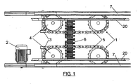
- Figures 1 and 2 show a drive system for a moving walkway including two horizontal drive chains, with reference number 1, driven by means of a motor 2 and a worm-gear type planar reducer 3.
- the output shaft of the reducer 3 moves in each case the gear wheel 4 which in turn drives the horizontal drive chains 1.
- These chains carry deformable rollers 5 engaging with opposing housings that the plates 6 of the moving walkway have on the rear surface.
- the horizontal chains 1 further include elements for driving the handrail 7, as will be described below.
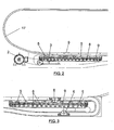
- Figures 2 and 3 show how the chain has lower rollers 8 moving on a guide 9 for supporting the movement of said chain.
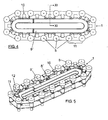
- Figures 4 and 5 show plan and perspective views of a horizontal drive chain for the drive system of the invention.
- the chain includes the rollers 5, formed from elastically deformable material and also carries arms 10, aimed in the same direction as the rollers 5 and which will be useful as a drive means for the handrail, as will be described below.
- the chain 1 has lower rollers 8' which are coupled on a guide 9', equivalent to the rollers 8 and guide 9 of Figure 3 , to support and guide the movement of the chain 1.
- Figure 6 shows a perspective view of one of the links 11 of the chains 1 with the elastically deformable rollers 5 and the arms 10, which can be provided with a coating 12 based on materials selected from deformable and resilient materials, the handrail 7 being supported against such coating for its drive by friction, as shown in Figure 13 .
- the rollers 5 engage in complementary cavities that the plates 6 of the walkway have at their back part when said plates run in coincidence with the section occupied by the drive chains 1, as will be explained with reference to Figures 7 to 10 .
- the drive chains 1 will be arranged such that the plates of the walkway are opposite to said chains along at least one straight section of the path of the belt, as has been shown in Figures 1 to 3 .
- the rollers 5 can be retractable, including a rod 14 which is assembled and can move axially on a bushing 15 of the chains 1.
- the rod 14 projects at the lower part and has assembled therein a wheel 16 supported on a guide 17 acting as a cam for moving the rod 14 in an upward direction until coupling it with the cavity 13 of the plates 6, when such plates run above the rollers 5.
- Figure 9 shows one of the rollers 5 coupled in the cavity 13 of one of the plates 6, which plates can be provided with means 19 of support on longitudinal guides 20 for their movement.
- the different plates of the walkway can be independent, moving by thrust from the plates 6 engaged with the drive chain 1, or they can linked to one another by means of shafts 21 perpendicular to the direction of movement of the walkway.
- Figure 10 shows a special side arrangement of the wheels 16 at the lower end of the rod 14 of the rollers 5, which wheels are housed along a guide 17, in the form of a channel, which will control the movement of the rod 14 both in the upward and in the downward direction, in order to pass it to a lower inoperative position, as is indicated with reference number 5' in Figure 10 , and an upper or active position, which is indicated with reference number 5" in the same figure, in which it is coupled in the lower cavity 13 of the plates 6.
- Figure 10 also shows the arms 10 carrying the upper coating 12 against which the handrail 7 will be supported for its drive.
- Figure 10 also shows one of the guides 20 which will drive and support the plates 6 of the walkway.
- Figures 11 and 12 show a horizontal arrangement of the drive chains 1, with rollers 5 of the drive chains coupled to plates 6 of the walkway and with the handrail 7 supported on the coating 12 of the arms 10, as can be better seen in Figure 15 corresponding to detail A of Figure 12 .
- Figure 14 shows the drive of the moving walkway by horizontal drive chains 1 by means of a linear motor.
- the chain is formed by a plurality of carriages 23 containing permanent magnets running through the fed part 24.
- the carriages 23 carry rollers 5 which will drive the plates 6, as well as the arms 10 which will drive the handrail 7.
- Figures 15 and 16 show the drive of the moving walkway by horizontal drive chains 1 by means of a permanent magnet synchronous motor 25 with a high torque at low speeds, placed such that it drives the wheels 4, which in turn move the horizontal chains 1 responsible for moving the conveyor plates 6, in the already described manner.
- Figure 17 shows the drive by horizontal drive chains 1 by means of a motor 2, as in the case of Figure 1 , reducer 26 and worm or worms 27 placed in a position to the walkway.
- the worm or worms 27 engage on actual bushings of the drive chains, and can consist of the same bushings 15 in which the rods 14 of the rollers 5 are assembled, as can be seen in Figure 10 , or of other elements of the chain arranged for the mentioned purpose.
- these chains carry deformable rollers 5 and the arms 10 for driving the handrail 7.
- Figure 18 shows the drive by horizontal drive chains 1 by means of two motors 2 and reducers 26 and worm or worms 27' placed in a position longitudinal to the walkway. As in the previous case, the worm or worms 27' engage on the actual bushings of the chain.
Landscapes
- Engineering & Computer Science (AREA)
- Mechanical Engineering (AREA)
- Escalators And Moving Walkways (AREA)
Description
- The present invention relates to a drive system for moving walkways and mechanical stairs, whereby the conveyor plates or steps as well as the handrail of a moving walkway or mechanical stairs move.
- More specifically, the system of the invention is of the type comprising a drive actuation mechanism and horizontal drive chains responsible for moving the plates of the walkway or steps of the mechanical stairs.
- Conventional passenger conveyor systems, such as mechanical stairs or moving walkways, include a chain of conveyor plates or steps moving in a circuit for the purpose of providing a continuous movement along a specific path. The conveyor plates or steps are connected to said chain circuit, which chain acts moved by a drive system. The drive system normally consists of a chain of conveyor plates, gear wheels, a shaft and an electric motor. The electric motor drives the shaft to which the gear wheels are integrally joined, which wheels transmit a movement to the links of the chain of conveyor plates or steps. Whenever the links of this chain move, the conveyor plates or steps move in the same way. The drive of the handrail in a conventional moving walkway or mechanical stairs takes power from the shaft to which the gear wheels driving the chain of conveyor plates or steps are integrally joined and drives, by means of several traction members, a wheel moving the mentioned handrail by friction.
- To assure a small speed fluctuation and minimize the polygonization effect in a conventional conveyor system, a large number of teeth are required in the drive wheel and this gives rise to a large diameter increasing the size of the upper and lower heads of the system, making a very deep pit for locating the walkway necessary. The link between the plate and the chain of conveyor plates is conventionally located under the surface of the plate. Given that the gap between two consecutive conveyor plates is closed for safety reasons, the transition radius in inclined walkways must be limited.
- Other types of drive mechanisms have been proposed which engage the belt at intermediate points such as those disclosed in
US Pat. No. 36773388 WO2004/063078A1 andWO2004/054919A1 . The common point of all the aforementioned inventions is that all of them propose using a linear drive system to move any type of chain joined to the conveyor plates or steps and, therefore, to drive the chains of conveyor plates or steps of the conveyor system. Nevertheless, the contact of metal with metal between the chain of the linear drive system and the links of chains joined to the conveyor plates or steps generates noise. The general configuration proposed in these documents does not allow reducing the dimensions of the walkway either. The general dimensions of conventional walkways are much larger than those that the present invention can offer. -
DE 2252134 A1 discloses a moving flat pavement for the transportation of passengers, having simultaneous conveyance into both directions, said pavement being formed by linked plates (2) moved by drive chains (5), whereby the drive chains (5) and the plates (2) have engagement means which are opposite and coupled to one another along at least a straight section of the path of the pavement, said means consisting in teeth associated to the drive chain (5) and racks (3) fixed to the lower portion of the plates (2). The teeth are not retractable relating to the position of the plates (2) and there is no possibility to interrupt temporarily the driving of the plates (2) by the driving chain (5). - The object of the present invention is a drive system for moving walkways and mechanical stairs provided with a drive system which allows improving the comfort and safety of the movement of the passenger, reducing the height of the upper and lower final sections of the conveyor system, reducing the cost of the system, eliminating the need to carry out civil work for creating pits and allowing a modular and therefore portable moving walkway system, in which the mechanisms necessary for driving the plates or steps of the walkway or mechanical stairs and the handrail thereof are furthermore reduced.
- The system of the invention comprises a drive actuation mechanism and horizontal drive chains responsible for causing the movement of the plates of the walkway or steps of the mechanical stairs. The plates of the walkway or steps of the mechanical stairs and the drive chain have mutual engagement means which allow directly transmitting the movement of the drive chain to the plates of the walkway or steps of the mechanical stairs, the drive chains being much shorter than the forward movement and return sections of the walkway or mechanical stairs. The plates of the walkway or steps of the mechanical stairs can be independent and transmit the movement to one another by thrust. The plates of the walkway or steps of the mechanical stairs can also be consecutively linked according to shafts perpendicular to the direction of movement of the walkway or mechanical stairs.
- The description of the invention will be made hereinafter with reference to a moving walkway and to the plates thereof, but it must be taken into account that the invention is also applicable to mechanical stairs and to the steps thereof.
- The engagement means between the chain and the plates are opposite and are coupled to one another along at least a straight section of the path of the belt. These means consist of deformable rollers which are assembled in the links of the drive chain and in complementary cavities that the plates of the walkway have at their back part. The rollers of the drive chain will run in a position opposite to the cavities of the plates or steps, along the mentioned straight section of the path of the belt or stairs and will penetrate said cavities to define the engagement means between the drive chain and the moving belt.
- The rollers of the drive chain can be retractable in a vertical direction between an extracted position, in which they engage in the cavity of the plates along the mentioned straight section of the path of the belt, and a retracted position, in which they do not engage with said cavities. To that end, the rollers can be supported on a guide defining a cam pushing them from the retracted position to the extracted position along the section in which they must engage with the plates of the walkway.
- According to another feature of the invention, the links of the drive chain furthermore carry the drive means of the handrail of the walkway. These means can consist of arms projecting from the links of the drive chain and are aimed towards the handrail, said arms being finished in a section that is supported and pressed against the band of the handrail, which action will have an effect on the straight section of engagement between the drive chain and the plates of the walkway. The handrail is driven by friction between the mentioned arms and the band of the handrail.
- As has already been indicated, the rollers forming part of the engagement means are of an elastically deformable nature.
- The walkway of the invention does not have a chain connecting the conveyor plates. The function of this chain is carried out by the actual conveyor plates, either by thrust, as has already been indicated, or because they are linked to one another according to shafts perpendicular to the direction of movement. This constitution allows using plates of a small dimension, in the direction of the movement, with respect to traditional plates, which will allow achieving a small radius in the return sections, thus being able to reduce the height of the walkway heads.
- A moving walkway or mechanical stairs incorporating the drive system of the invention allows an important saving from the manufacturing point of view because the band of plates and the handrail is moved with a single drive chain, eliminating intermediate drives. This saving improves the mechanical losses, noise and vibrations that elements such as chains, shafts, gears and gear wheels cause in traditional moving mechanical stairs and walkways.
- The system of the invention further allows achieving groups of compact walkways or mechanical stairs which prevent having to make very deep pits for housing the final heads.
- In the event that the different plates are consecutively linked to one another by means of shafts perpendicular to the direction of movement of the walkway, as has already been indicated, the joint between plates can be located close to the rolling surface, thus allowing a small transition radius in inclined walkways.
- In the case of very long walkways, multiple drive modules can be used.
- In the system of the invention, the engagement between the drive chains and the band of conveyor plates can take place on one side, on both sides or in the center. Furthermore, the drive chains and therefore the engagement between these chains and the plates of the belt can occur in any section of the path described by the belt.
- The engagement feet between the chain and the plates of the walkway can further comprise a plurality of protrusions in the form of teeth projecting from the links of the chain and can be coupled in an identical number of opposing housings that the plates have on their rear surface, forming a second engagement between the drive chain and the conveyor plates.
- The drive rollers can be made of materials selected from deformable and resilient materials. The drive rollers can also be laminated with an outer layer comprising materials of the indicated type.
- The drive rollers can also be made or polymeric materials or materials laminated with a second outer layer of these materials. Polymeric materials can be selected from elastomers, polyurethanes and combinations thereof.
- The drive chain can further include bushings including an outer layer based on materials selected from deformable and resilient materials, which can also be obtained based on polymeric materials.
- With these constitutions, the engagement between the different elements involved in the transmission of movement is smoother than if a metal-metal contact existed, which involves a more silent operation and with cushioned contacts between the engagement start and end times, in addition to extending the useful life of said elements.
- The same constitution can be applied to the elements driving the handrail.
- The drive actuation mechanism for the system of the invention can be formed by means of an worm-gear type planar reducer and electric motor, by means of a linear motor, by means of a motor without a reducer, by means of a worm and electric motor, etc.
- The attached drawings show a non-limiting embodiment of a drive system for moving walkways and mechanical stairs, formed according to the invention and with the aid of which the features and advantages of said system can be better understood.
- In the drawings:
-
Figure 1 shows a plan view of a drive system by means of a worm-gear type planar reducer and motor for a moving walkway formed according to the invention. -
Figure 2 shows a side elevational view of the drive system ofFigure 1 . -
Figure 3 shows a side elevational view of the horizontal drive chain of the conveyor plates, with a guiding system by means of rollers and a horizontal guide. -
Figures 4 and 5 show a plan and perspective view of the drive chain with a guiding system by means of wheels and a guide. -
Figure 6 shows a perspective view of a link of the drive chain shown inFigures 4 and 5 . -
Figure 7 shows a bottom perspective view of the engagement between the rollers of the drive chain and one of the plates of the walkway. -
Figure 8 shows a longitudinal section of the drive chain, taken according to section line VIII-VIII ofFigure 7 , showing the engagement between the rollers of the chain and one of the plates of the walkway. -
Figure 9 shows, on a larger scale, a sectional view according to section line IX-IX ofFigure 8 of the engagement between one of the rollers of the chain and one of the plates of the walkway. -
Figure 10 shows a cross-sectional view of the walkway and drive chain, taken according to section line X-X ofFigure 8 . -
Figures 11 and 12 show side elevational and cross-sectional views according to section line XII-XII ofFigure 11 of a possible arrangement of the drive chains. -
Figure 13 corresponds to detail A ofFigure 12 , on a larger scale, in which the drive of the handrail is seen. -
Figure 14 shows a plan view of the drive by means of a linear motor. -
Figure 15 shows a plan view of the drive by means of a permanent magnet synchronous motor. -
Figure 16 shows an elevational view of the drive by means of a permanent magnet synchronous motor. -
Figure 17 shows a plan view of the drive by means of a transverse worm. -
Figure 18 shows a plan view of the drive by means of longitudinal worms. - A detailed description of a drive system for a moving walkway formed according to the invention will be made below, and it must be understood that the described concepts are equally applicable to moving mechanical stairs and other conveyor systems.
-
Figures 1 and2 show a drive system for a moving walkway including two horizontal drive chains, withreference number 1, driven by means of amotor 2 and a worm-gear typeplanar reducer 3. The output shaft of thereducer 3 moves in each case thegear wheel 4 which in turn drives thehorizontal drive chains 1. These chains carrydeformable rollers 5 engaging with opposing housings that theplates 6 of the moving walkway have on the rear surface. Thehorizontal chains 1 further include elements for driving thehandrail 7, as will be described below. -
Figures 2 and 3 show how the chain haslower rollers 8 moving on aguide 9 for supporting the movement of said chain. -
Figures 4 and 5 show plan and perspective views of a horizontal drive chain for the drive system of the invention. The chain includes therollers 5, formed from elastically deformable material and also carriesarms 10, aimed in the same direction as therollers 5 and which will be useful as a drive means for the handrail, as will be described below. - In the embodiment shown in
Figures 4 and 5 , thechain 1 has lower rollers 8' which are coupled on a guide 9', equivalent to therollers 8 and guide 9 ofFigure 3 , to support and guide the movement of thechain 1. -
Figure 6 shows a perspective view of one of thelinks 11 of thechains 1 with the elasticallydeformable rollers 5 and thearms 10, which can be provided with acoating 12 based on materials selected from deformable and resilient materials, thehandrail 7 being supported against such coating for its drive by friction, as shown inFigure 13 . - The
rollers 5 engage in complementary cavities that theplates 6 of the walkway have at their back part when said plates run in coincidence with the section occupied by thedrive chains 1, as will be explained with reference toFigures 7 to 10 . Thedrive chains 1 will be arranged such that the plates of the walkway are opposite to said chains along at least one straight section of the path of the belt, as has been shown inFigures 1 to 3 . - As can be seen in
Figures 7 and8 , when theplates 6 of the walkway run in coincidence with thedrive chains 1, therollers 5 are coupled in complementary cavities that theplates 6 have at their back part, mutually engaging to be useful as a drive means for said plates. - As can be seen in
Figure 8 , therollers 5 can be retractable, including arod 14 which is assembled and can move axially on abushing 15 of thechains 1. Therod 14 projects at the lower part and has assembled therein awheel 16 supported on aguide 17 acting as a cam for moving therod 14 in an upward direction until coupling it with thecavity 13 of theplates 6, when such plates run above therollers 5. -
Figure 9 shows one of therollers 5 coupled in thecavity 13 of one of theplates 6, which plates can be provided withmeans 19 of support onlongitudinal guides 20 for their movement. - As has been indicated above, the different plates of the walkway can be independent, moving by thrust from the
plates 6 engaged with thedrive chain 1, or they can linked to one another by means ofshafts 21 perpendicular to the direction of movement of the walkway. -
Figure 10 shows a special side arrangement of thewheels 16 at the lower end of therod 14 of therollers 5, which wheels are housed along aguide 17, in the form of a channel, which will control the movement of therod 14 both in the upward and in the downward direction, in order to pass it to a lower inoperative position, as is indicated with reference number 5' inFigure 10 , and an upper or active position, which is indicated withreference number 5" in the same figure, in which it is coupled in thelower cavity 13 of theplates 6.Figure 10 also shows thearms 10 carrying theupper coating 12 against which thehandrail 7 will be supported for its drive.Figure 10 also shows one of theguides 20 which will drive and support theplates 6 of the walkway. -
Figures 11 and 12 show a horizontal arrangement of thedrive chains 1, withrollers 5 of the drive chains coupled toplates 6 of the walkway and with thehandrail 7 supported on thecoating 12 of thearms 10, as can be better seen inFigure 15 corresponding to detail A ofFigure 12 . -
Figure 14 shows the drive of the moving walkway byhorizontal drive chains 1 by means of a linear motor. The chain is formed by a plurality ofcarriages 23 containing permanent magnets running through thefed part 24. Thecarriages 23 carryrollers 5 which will drive theplates 6, as well as thearms 10 which will drive thehandrail 7. -
Figures 15 and 16 show the drive of the moving walkway byhorizontal drive chains 1 by means of a permanentmagnet synchronous motor 25 with a high torque at low speeds, placed such that it drives thewheels 4, which in turn move thehorizontal chains 1 responsible for moving theconveyor plates 6, in the already described manner. -
Figure 17 shows the drive byhorizontal drive chains 1 by means of amotor 2, as in the case ofFigure 1 ,reducer 26 and worm orworms 27 placed in a position to the walkway. The worm orworms 27 engage on actual bushings of the drive chains, and can consist of thesame bushings 15 in which therods 14 of therollers 5 are assembled, as can be seen inFigure 10 , or of other elements of the chain arranged for the mentioned purpose. As in the previous cases, these chains carrydeformable rollers 5 and thearms 10 for driving thehandrail 7. - Finally,
Figure 18 shows the drive byhorizontal drive chains 1 by means of twomotors 2 andreducers 26 and worm or worms 27' placed in a position longitudinal to the walkway. As in the previous case, the worm or worms 27' engage on the actual bushings of the chain.
Claims (7)
- A drive system for moving walkways and mechanical stairs by means of horizontal drive chains (1), comprising a drive actuation mechanism and drive chains responsible for causing the movement of the plates (6) of the moving walkway or steps of the mechanical stairs, wherein the drive chains (1) and the plates (6) or steps have direct mutual engagement means, which are opposite and coupled to one another along at least a straight section of the path of the belt or stairs, characterised in that said engagement means consist of deformable rollers (5, 5', 5") which are assembled in the links (11) of the drive chain (1) and engage in complementary cavities (13) that the plates (6) or steps have at the back part; the rollers (5, 5', 5") of the drive chain (1) running in a position opposite to the cavities (13) of the plates (6) or steps along the mentioned straight section of the path of the belt or stairs and penetrating said cavities (13) to define the engagement means between the drive chain (1) and the belt or stairs, whereby the rollers (5-5'-5") of the drive chains (1) are retractable in a vertical direction between an extracted position, in which they engage in the cavities (13) of the plates (6) or steps along the mentioned straight section of the path of the belt or stairs, and a retracted position in which they are separated from the plates (6) or steps and do not engage with said cavities (13), said rollers (5-5'-5") being supported on a guide (17) defining a cam pushing them from the retracted position to the extracted position along the section in which they must engage with the plates (6) of the moving walkway, or steps of the mechanical stairs.
- A system according to claim 1, characterized in that the links (11) of the drive chains (1) carry drive means for the handrail (7) of the moving walkway or mechanical stairs.
- A system according to claim 2, characterized in that the mentioned means consist of arms (10) projecting from the links (11) of the drive chains (1), aimed towards the handrail (7) and finished in a section that is supported and pressed against the band of the mentioned handrail (7), in the mentioned straight section of the path of the belt or stairs, for the drive by friction of said band.
- A system according to claim 1, characterized in that the drive of the horizontal drive chains (1) is carried out by means of one or more worm-gear type planar reducers (26).
- A system according to claim 1, characterized in that the drive of the horizontal drive chains (1) is carried out by means of one or more linear motors (2).
- A system according to claim 1, characterized in that the drive of the drive chains (1) is carried out by means of one or more permanent magnet synchronous motors (25) with a high torque at low speeds.
- A system according to claim 1, characterized in that the drive of the drive chains (1) is carried out by means of one or more worms (27, 27') engaging directly in bushings (15) or elements of said chains (1).
Applications Claiming Priority (1)
| Application Number | Priority Date | Filing Date | Title |
|---|---|---|---|
| ES200702989A ES2301440B1 (en) | 2007-11-12 | 2007-11-12 | SYSTEM OF OPERATION OF CORRIDORS AND MOBILE STAIRS. |
Publications (2)
| Publication Number | Publication Date |
|---|---|
| EP2058263A1 EP2058263A1 (en) | 2009-05-13 |
| EP2058263B1 true EP2058263B1 (en) | 2012-06-06 |
Family
ID=39469738
Family Applications (1)
| Application Number | Title | Priority Date | Filing Date |
|---|---|---|---|
| EP08380207A Not-in-force EP2058263B1 (en) | 2007-11-12 | 2008-07-08 | Drive system for moving walkways and escalators |
Country Status (4)
| Country | Link |
|---|---|
| US (1) | US7686152B2 (en) |
| EP (1) | EP2058263B1 (en) |
| CN (1) | CN101434361B (en) |
| ES (2) | ES2301440B1 (en) |
Cited By (2)
| Publication number | Priority date | Publication date | Assignee | Title |
|---|---|---|---|---|
| WO2020001960A1 (en) * | 2018-06-25 | 2020-01-02 | Inventio Ag | Drive assembly for a moving walkway and correspondingly equipped flat-structure moving walkway |
| WO2020001961A1 (en) * | 2018-06-25 | 2020-01-02 | Inventio Ag | Drive assembly for a moving walkway and correspondingly equipped flat-structure moving walkway |
Families Citing this family (4)
| Publication number | Priority date | Publication date | Assignee | Title |
|---|---|---|---|---|
| DE102009017076B4 (en) * | 2009-04-09 | 2012-06-28 | Kone Corp. | Equipment for passenger transport |
| ES2342532B1 (en) * | 2009-12-29 | 2011-05-20 | Thyssenkrupp Elevator Innovation Center S.A. | DRIVE SYSTEM FOR STAIRS AND MOBILE CORRIDORS. |
| CN103582605B (en) | 2011-05-23 | 2017-04-05 | 奥的斯电梯公司 | The method of the polygon effect in polygon compensation system of connections, passenger conveyor system and reduction chain drive system |
| US11230459B2 (en) * | 2020-06-26 | 2022-01-25 | Otis Elevator Company | Belt-driven escalator |
Family Cites Families (19)
| Publication number | Priority date | Publication date | Assignee | Title |
|---|---|---|---|---|
| US1775029A (en) * | 1929-07-13 | 1930-09-02 | Creamery Package Mfg Co | Intermittent drive for endless conveyers |
| BE568575A (en) * | 1957-06-26 | |||
| US3365051A (en) * | 1964-06-25 | 1968-01-23 | Westinghouse Electric Corp | Moving walk |
| US3321060A (en) * | 1965-10-29 | 1967-05-23 | Westinghouse Electric Corp | Passenger conveyors employing handrails |
| US3677388A (en) | 1970-11-23 | 1972-07-18 | Westinghouse Electric Corp | Modular drive unit for a conveyor |
| DE2252134A1 (en) * | 1972-10-24 | 1974-04-25 | Pohlig Heckel Bleichert | MOVING WALK FOR PERSONAL TRANSPORT |
| US4082173A (en) * | 1976-06-10 | 1978-04-04 | Otis Elevator Company | Drive unit for an endless conveyor |
| US4361220A (en) * | 1981-02-25 | 1982-11-30 | Westinghouse Electric Corp. | Drive chain |
| US6119848A (en) * | 1999-01-22 | 2000-09-19 | Hartness International | Conveyor motor drive unit and conveyor system |
| US6540060B1 (en) * | 2001-10-30 | 2003-04-01 | Otis Elevator Company | Belt drive assembly for a passenger conveyor |
| JP3952778B2 (en) * | 2002-01-08 | 2007-08-01 | 株式会社日立製作所 | Passenger conveyor |
| US6997302B2 (en) * | 2002-05-20 | 2006-02-14 | Otis Elevator Company | Escalator drive mechanism with failure detection and backup |
| JP4292158B2 (en) | 2002-12-13 | 2009-07-08 | オーチス エレベータ カンパニー | Step chain link for escalator |
| AU2003214807A1 (en) * | 2003-01-07 | 2004-08-10 | Otis Elevator Company | Drive belt for a passenger conveyor |
| US20060011450A1 (en) * | 2003-01-07 | 2006-01-19 | Fargo Richard N | Drive belt for a passenger conveyor |
| WO2004063078A1 (en) | 2003-01-07 | 2004-07-29 | Otis Elevator Company | Passenger conveyor drive module arrangement |
| JP2006160494A (en) * | 2004-12-09 | 2006-06-22 | Mitsubishi Electric Corp | Passenger conveyor drive |
| JP2007284155A (en) * | 2006-04-12 | 2007-11-01 | Toshiba Elevator Co Ltd | Passenger conveyor |
| JP5126880B2 (en) * | 2006-08-31 | 2013-01-23 | 東芝エレベータ株式会社 | Conveyor device |
-
2007
- 2007-11-12 ES ES200702989A patent/ES2301440B1/en not_active Expired - Fee Related
-
2008
- 2008-07-08 EP EP08380207A patent/EP2058263B1/en not_active Not-in-force
- 2008-07-08 ES ES08380207T patent/ES2389316T3/en active Active
- 2008-09-01 CN CN2008102111751A patent/CN101434361B/en not_active Expired - Fee Related
- 2008-10-14 US US12/251,284 patent/US7686152B2/en not_active Expired - Fee Related
Cited By (2)
| Publication number | Priority date | Publication date | Assignee | Title |
|---|---|---|---|---|
| WO2020001960A1 (en) * | 2018-06-25 | 2020-01-02 | Inventio Ag | Drive assembly for a moving walkway and correspondingly equipped flat-structure moving walkway |
| WO2020001961A1 (en) * | 2018-06-25 | 2020-01-02 | Inventio Ag | Drive assembly for a moving walkway and correspondingly equipped flat-structure moving walkway |
Also Published As
| Publication number | Publication date |
|---|---|
| ES2301440B1 (en) | 2009-08-24 |
| EP2058263A1 (en) | 2009-05-13 |
| ES2389316T3 (en) | 2012-10-25 |
| CN101434361B (en) | 2013-11-06 |
| CN101434361A (en) | 2009-05-20 |
| US20090120762A1 (en) | 2009-05-14 |
| ES2301440A1 (en) | 2008-06-16 |
| US7686152B2 (en) | 2010-03-30 |
Similar Documents
| Publication | Publication Date | Title |
|---|---|---|
| US7686152B2 (en) | Drive system for moving walkways and stairs | |
| US7926641B2 (en) | Conveyor system for the transport of passengers/goods | |
| US8585015B2 (en) | Engagement chain | |
| EP2546183B1 (en) | Moving walkway | |
| US5921351A (en) | Modular drive mechanism for a passenger conveyor | |
| EP2341028B1 (en) | Drive system for escalators and moving walkways | |
| US5295568A (en) | Passenger conveyor and treadboard construction for passenger conveyor | |
| WO2002026612B1 (en) | Escalator drive machine with drive belts for simultaneously propelling handrail and conveyor surface | |
| CN100537394C (en) | Passenger conveyor drive machine | |
| AU2004203530B2 (en) | Drive equipment for escalator step or moving walkway plate | |
| AU2004203529A1 (en) | Drive equipment for escalator step or moving walkway plate | |
| EP2938567B1 (en) | Conveyor system for the transport of passengers/goods | |
| EP2065328B1 (en) | Conveyor system for the transport of passengers/goods. | |
| CN101746661B (en) | Passenger delivery device | |
| EP2872434B1 (en) | Drive system for passenger conveyor | |
| EP2570378B1 (en) | Bidirectional moving walkway | |
| CN101157430B (en) | Passenger conveyor | |
| US20120024675A1 (en) | Drive assembly for a passenger conveyor | |
| WO2013052032A1 (en) | Drive assembly for a passenger conveyor | |
| CN101258091A (en) | Passenger Conveyor Unit | |
| CN219078824U (en) | Power transmission device for passenger conveying system and passenger conveying system | |
| JP2009173378A (en) | Conveyor system for passenger/article transportation | |
| EP1870371A1 (en) | Passenger conveyor | |
| KR0125893Y1 (en) | Handrail drive equipment of escalator | |
| HK1086242B (en) | Passenger conveyor drive machine |
Legal Events
| Date | Code | Title | Description |
|---|---|---|---|
| PUAI | Public reference made under article 153(3) epc to a published international application that has entered the european phase |
Free format text: ORIGINAL CODE: 0009012 |
|
| AK | Designated contracting states |
Kind code of ref document: A1 Designated state(s): AT BE BG CH CY CZ DE DK EE ES FI FR GB GR HR HU IE IS IT LI LT LU LV MC MT NL NO PL PT RO SE SI SK TR |
|
| AX | Request for extension of the european patent |
Extension state: AL BA MK RS |
|
| 17P | Request for examination filed |
Effective date: 20090730 |
|
| 17Q | First examination report despatched |
Effective date: 20091014 |
|
| AKX | Designation fees paid |
Designated state(s): AT BE BG CH CY CZ DE DK EE ES FI FR GB GR HR HU IE IS IT LI LT LU LV MC MT NL NO PL PT RO SE SI SK TR |
|
| GRAJ | Information related to disapproval of communication of intention to grant by the applicant or resumption of examination proceedings by the epo deleted |
Free format text: ORIGINAL CODE: EPIDOSDIGR1 |
|
| GRAP | Despatch of communication of intention to grant a patent |
Free format text: ORIGINAL CODE: EPIDOSNIGR1 |
|
| GRAP | Despatch of communication of intention to grant a patent |
Free format text: ORIGINAL CODE: EPIDOSNIGR1 |
|
| RAP1 | Party data changed (applicant data changed or rights of an application transferred) |
Owner name: THYSSENKRUPP ELEVATOR INNOVATION CENTER S.A. Owner name: THYSSENKRUPP ELEVATOR (ES/PBB) LTD. |
|
| GRAS | Grant fee paid |
Free format text: ORIGINAL CODE: EPIDOSNIGR3 |
|
| GRAA | (expected) grant |
Free format text: ORIGINAL CODE: 0009210 |
|
| AK | Designated contracting states |
Kind code of ref document: B1 Designated state(s): AT BE BG CH CY CZ DE DK EE ES FI FR GB GR HR HU IE IS IT LI LT LU LV MC MT NL NO PL PT RO SE SI SK TR |
|
| REG | Reference to a national code |
Ref country code: GB Ref legal event code: FG4D |
|
| REG | Reference to a national code |
Ref country code: AT Ref legal event code: REF Ref document number: 560937 Country of ref document: AT Kind code of ref document: T Effective date: 20120615 Ref country code: CH Ref legal event code: EP |
|
| REG | Reference to a national code |
Ref country code: IE Ref legal event code: FG4D |
|
| REG | Reference to a national code |
Ref country code: DE Ref legal event code: R096 Ref document number: 602008016163 Country of ref document: DE Effective date: 20120802 |
|
| REG | Reference to a national code |
Ref country code: NL Ref legal event code: T3 |
|
| REG | Reference to a national code |
Ref country code: CH Ref legal event code: NV Representative=s name: JACOBACCI & PARTNERS S.P.A. |
|
| REG | Reference to a national code |
Ref country code: ES Ref legal event code: FG2A Ref document number: 2389316 Country of ref document: ES Kind code of ref document: T3 Effective date: 20121025 |
|
| PG25 | Lapsed in a contracting state [announced via postgrant information from national office to epo] |
Ref country code: NO Free format text: LAPSE BECAUSE OF FAILURE TO SUBMIT A TRANSLATION OF THE DESCRIPTION OR TO PAY THE FEE WITHIN THE PRESCRIBED TIME-LIMIT Effective date: 20120906 Ref country code: SE Free format text: LAPSE BECAUSE OF FAILURE TO SUBMIT A TRANSLATION OF THE DESCRIPTION OR TO PAY THE FEE WITHIN THE PRESCRIBED TIME-LIMIT Effective date: 20120606 Ref country code: LT Free format text: LAPSE BECAUSE OF FAILURE TO SUBMIT A TRANSLATION OF THE DESCRIPTION OR TO PAY THE FEE WITHIN THE PRESCRIBED TIME-LIMIT Effective date: 20120606 Ref country code: CY Free format text: LAPSE BECAUSE OF FAILURE TO SUBMIT A TRANSLATION OF THE DESCRIPTION OR TO PAY THE FEE WITHIN THE PRESCRIBED TIME-LIMIT Effective date: 20120606 |
|
| REG | Reference to a national code |
Ref country code: LT Ref legal event code: MG4D Effective date: 20120606 |
|
| PG25 | Lapsed in a contracting state [announced via postgrant information from national office to epo] |
Ref country code: HR Free format text: LAPSE BECAUSE OF FAILURE TO SUBMIT A TRANSLATION OF THE DESCRIPTION OR TO PAY THE FEE WITHIN THE PRESCRIBED TIME-LIMIT Effective date: 20120606 Ref country code: SI Free format text: LAPSE BECAUSE OF FAILURE TO SUBMIT A TRANSLATION OF THE DESCRIPTION OR TO PAY THE FEE WITHIN THE PRESCRIBED TIME-LIMIT Effective date: 20120606 Ref country code: LV Free format text: LAPSE BECAUSE OF FAILURE TO SUBMIT A TRANSLATION OF THE DESCRIPTION OR TO PAY THE FEE WITHIN THE PRESCRIBED TIME-LIMIT Effective date: 20120606 |
|
| PG25 | Lapsed in a contracting state [announced via postgrant information from national office to epo] |
Ref country code: CZ Free format text: LAPSE BECAUSE OF FAILURE TO SUBMIT A TRANSLATION OF THE DESCRIPTION OR TO PAY THE FEE WITHIN THE PRESCRIBED TIME-LIMIT Effective date: 20120606 Ref country code: EE Free format text: LAPSE BECAUSE OF FAILURE TO SUBMIT A TRANSLATION OF THE DESCRIPTION OR TO PAY THE FEE WITHIN THE PRESCRIBED TIME-LIMIT Effective date: 20120606 Ref country code: SK Free format text: LAPSE BECAUSE OF FAILURE TO SUBMIT A TRANSLATION OF THE DESCRIPTION OR TO PAY THE FEE WITHIN THE PRESCRIBED TIME-LIMIT Effective date: 20120606 Ref country code: IS Free format text: LAPSE BECAUSE OF FAILURE TO SUBMIT A TRANSLATION OF THE DESCRIPTION OR TO PAY THE FEE WITHIN THE PRESCRIBED TIME-LIMIT Effective date: 20121006 Ref country code: RO Free format text: LAPSE BECAUSE OF FAILURE TO SUBMIT A TRANSLATION OF THE DESCRIPTION OR TO PAY THE FEE WITHIN THE PRESCRIBED TIME-LIMIT Effective date: 20120606 Ref country code: BE Free format text: LAPSE BECAUSE OF FAILURE TO SUBMIT A TRANSLATION OF THE DESCRIPTION OR TO PAY THE FEE WITHIN THE PRESCRIBED TIME-LIMIT Effective date: 20120606 |
|
| PG25 | Lapsed in a contracting state [announced via postgrant information from national office to epo] |
Ref country code: PT Free format text: LAPSE BECAUSE OF FAILURE TO SUBMIT A TRANSLATION OF THE DESCRIPTION OR TO PAY THE FEE WITHIN THE PRESCRIBED TIME-LIMIT Effective date: 20121008 Ref country code: PL Free format text: LAPSE BECAUSE OF FAILURE TO SUBMIT A TRANSLATION OF THE DESCRIPTION OR TO PAY THE FEE WITHIN THE PRESCRIBED TIME-LIMIT Effective date: 20120606 Ref country code: MC Free format text: LAPSE BECAUSE OF NON-PAYMENT OF DUE FEES Effective date: 20120731 |
|
| PLBE | No opposition filed within time limit |
Free format text: ORIGINAL CODE: 0009261 |
|
| STAA | Information on the status of an ep patent application or granted ep patent |
Free format text: STATUS: NO OPPOSITION FILED WITHIN TIME LIMIT |
|
| PG25 | Lapsed in a contracting state [announced via postgrant information from national office to epo] |
Ref country code: DK Free format text: LAPSE BECAUSE OF FAILURE TO SUBMIT A TRANSLATION OF THE DESCRIPTION OR TO PAY THE FEE WITHIN THE PRESCRIBED TIME-LIMIT Effective date: 20120606 |
|
| REG | Reference to a national code |
Ref country code: IE Ref legal event code: MM4A |
|
| 26N | No opposition filed |
Effective date: 20130307 |
|
| REG | Reference to a national code |
Ref country code: DE Ref legal event code: R097 Ref document number: 602008016163 Country of ref document: DE Effective date: 20130307 |
|
| PG25 | Lapsed in a contracting state [announced via postgrant information from national office to epo] |
Ref country code: IE Free format text: LAPSE BECAUSE OF NON-PAYMENT OF DUE FEES Effective date: 20120708 Ref country code: BG Free format text: LAPSE BECAUSE OF FAILURE TO SUBMIT A TRANSLATION OF THE DESCRIPTION OR TO PAY THE FEE WITHIN THE PRESCRIBED TIME-LIMIT Effective date: 20120906 Ref country code: MT Free format text: LAPSE BECAUSE OF FAILURE TO SUBMIT A TRANSLATION OF THE DESCRIPTION OR TO PAY THE FEE WITHIN THE PRESCRIBED TIME-LIMIT Effective date: 20120606 |
|
| PG25 | Lapsed in a contracting state [announced via postgrant information from national office to epo] |
Ref country code: TR Free format text: LAPSE BECAUSE OF FAILURE TO SUBMIT A TRANSLATION OF THE DESCRIPTION OR TO PAY THE FEE WITHIN THE PRESCRIBED TIME-LIMIT Effective date: 20120606 |
|
| PG25 | Lapsed in a contracting state [announced via postgrant information from national office to epo] |
Ref country code: LU Free format text: LAPSE BECAUSE OF NON-PAYMENT OF DUE FEES Effective date: 20120708 |
|
| PG25 | Lapsed in a contracting state [announced via postgrant information from national office to epo] |
Ref country code: HU Free format text: LAPSE BECAUSE OF FAILURE TO SUBMIT A TRANSLATION OF THE DESCRIPTION OR TO PAY THE FEE WITHIN THE PRESCRIBED TIME-LIMIT Effective date: 20080708 |
|
| PG25 | Lapsed in a contracting state [announced via postgrant information from national office to epo] |
Ref country code: GR Free format text: LAPSE BECAUSE OF FAILURE TO SUBMIT A TRANSLATION OF THE DESCRIPTION OR TO PAY THE FEE WITHIN THE PRESCRIBED TIME-LIMIT Effective date: 20120606 |
|
| REG | Reference to a national code |
Ref country code: CH Ref legal event code: PCAR Free format text: NEW ADDRESS: VIA LUGANETTO 3, 6962 LUGANO (CH) |
|
| REG | Reference to a national code |
Ref country code: FR Ref legal event code: PLFP Year of fee payment: 9 |
|
| REG | Reference to a national code |
Ref country code: FR Ref legal event code: PLFP Year of fee payment: 10 |
|
| PGFP | Annual fee paid to national office [announced via postgrant information from national office to epo] |
Ref country code: NL Payment date: 20170719 Year of fee payment: 10 |
|
| PGFP | Annual fee paid to national office [announced via postgrant information from national office to epo] |
Ref country code: CH Payment date: 20170719 Year of fee payment: 10 Ref country code: ES Payment date: 20170825 Year of fee payment: 10 Ref country code: GB Payment date: 20170719 Year of fee payment: 10 Ref country code: IT Payment date: 20170728 Year of fee payment: 10 Ref country code: FI Payment date: 20170720 Year of fee payment: 10 Ref country code: FR Payment date: 20170724 Year of fee payment: 10 Ref country code: DE Payment date: 20170724 Year of fee payment: 10 |
|
| PGFP | Annual fee paid to national office [announced via postgrant information from national office to epo] |
Ref country code: AT Payment date: 20170720 Year of fee payment: 10 |
|
| REG | Reference to a national code |
Ref country code: DE Ref legal event code: R119 Ref document number: 602008016163 Country of ref document: DE |
|
| REG | Reference to a national code |
Ref country code: CH Ref legal event code: PL |
|
| REG | Reference to a national code |
Ref country code: NL Ref legal event code: MM Effective date: 20180801 |
|
| REG | Reference to a national code |
Ref country code: AT Ref legal event code: MM01 Ref document number: 560937 Country of ref document: AT Kind code of ref document: T Effective date: 20180708 |
|
| GBPC | Gb: european patent ceased through non-payment of renewal fee |
Effective date: 20180708 |
|
| PG25 | Lapsed in a contracting state [announced via postgrant information from national office to epo] |
Ref country code: FI Free format text: LAPSE BECAUSE OF NON-PAYMENT OF DUE FEES Effective date: 20180708 Ref country code: AT Free format text: LAPSE BECAUSE OF NON-PAYMENT OF DUE FEES Effective date: 20180708 Ref country code: GB Free format text: LAPSE BECAUSE OF NON-PAYMENT OF DUE FEES Effective date: 20180708 Ref country code: FR Free format text: LAPSE BECAUSE OF NON-PAYMENT OF DUE FEES Effective date: 20180731 Ref country code: LI Free format text: LAPSE BECAUSE OF NON-PAYMENT OF DUE FEES Effective date: 20180731 Ref country code: DE Free format text: LAPSE BECAUSE OF NON-PAYMENT OF DUE FEES Effective date: 20190201 Ref country code: CH Free format text: LAPSE BECAUSE OF NON-PAYMENT OF DUE FEES Effective date: 20180731 |
|
| PG25 | Lapsed in a contracting state [announced via postgrant information from national office to epo] |
Ref country code: NL Free format text: LAPSE BECAUSE OF NON-PAYMENT OF DUE FEES Effective date: 20180801 |
|
| PG25 | Lapsed in a contracting state [announced via postgrant information from national office to epo] |
Ref country code: IT Free format text: LAPSE BECAUSE OF NON-PAYMENT OF DUE FEES Effective date: 20180708 |
|
| REG | Reference to a national code |
Ref country code: ES Ref legal event code: FD2A Effective date: 20190917 |
|
| PG25 | Lapsed in a contracting state [announced via postgrant information from national office to epo] |
Ref country code: ES Free format text: LAPSE BECAUSE OF NON-PAYMENT OF DUE FEES Effective date: 20180709 |