EP2058236A1 - Packing member for honeycomb structured body and method for transporting honeycomb structured body - Google Patents
Packing member for honeycomb structured body and method for transporting honeycomb structured body Download PDFInfo
- Publication number
- EP2058236A1 EP2058236A1 EP08014843A EP08014843A EP2058236A1 EP 2058236 A1 EP2058236 A1 EP 2058236A1 EP 08014843 A EP08014843 A EP 08014843A EP 08014843 A EP08014843 A EP 08014843A EP 2058236 A1 EP2058236 A1 EP 2058236A1
- Authority
- EP
- European Patent Office
- Prior art keywords
- honeycomb structured
- structured bodies
- holding member
- packing
- structured body
- Prior art date
- Legal status (The legal status is an assumption and is not a legal conclusion. Google has not performed a legal analysis and makes no representation as to the accuracy of the status listed.)
- Granted
Links
Images


Classifications
-
- B—PERFORMING OPERATIONS; TRANSPORTING
- B65—CONVEYING; PACKING; STORING; HANDLING THIN OR FILAMENTARY MATERIAL
- B65D—CONTAINERS FOR STORAGE OR TRANSPORT OF ARTICLES OR MATERIALS, e.g. BAGS, BARRELS, BOTTLES, BOXES, CANS, CARTONS, CRATES, DRUMS, JARS, TANKS, HOPPERS, FORWARDING CONTAINERS; ACCESSORIES, CLOSURES, OR FITTINGS THEREFOR; PACKAGING ELEMENTS; PACKAGES
- B65D5/00—Rigid or semi-rigid containers of polygonal cross-section, e.g. boxes, cartons or trays, formed by folding or erecting one or more blanks made of paper
- B65D5/42—Details of containers or of foldable or erectable container blanks
- B65D5/44—Integral, inserted or attached portions forming internal or external fittings
- B65D5/50—Internal supporting or protecting elements for contents
- B65D5/5028—Elements formed separately from the container body
-
- B—PERFORMING OPERATIONS; TRANSPORTING
- B65—CONVEYING; PACKING; STORING; HANDLING THIN OR FILAMENTARY MATERIAL
- B65D—CONTAINERS FOR STORAGE OR TRANSPORT OF ARTICLES OR MATERIALS, e.g. BAGS, BARRELS, BOTTLES, BOXES, CANS, CARTONS, CRATES, DRUMS, JARS, TANKS, HOPPERS, FORWARDING CONTAINERS; ACCESSORIES, CLOSURES, OR FITTINGS THEREFOR; PACKAGING ELEMENTS; PACKAGES
- B65D81/00—Containers, packaging elements, or packages, for contents presenting particular transport or storage problems, or adapted to be used for non-packaging purposes after removal of contents
- B65D81/02—Containers, packaging elements, or packages, for contents presenting particular transport or storage problems, or adapted to be used for non-packaging purposes after removal of contents specially adapted to protect contents from mechanical damage
- B65D81/05—Containers, packaging elements, or packages, for contents presenting particular transport or storage problems, or adapted to be used for non-packaging purposes after removal of contents specially adapted to protect contents from mechanical damage maintaining contents at spaced relation from package walls, or from other contents
-
- B—PERFORMING OPERATIONS; TRANSPORTING
- B65—CONVEYING; PACKING; STORING; HANDLING THIN OR FILAMENTARY MATERIAL
- B65D—CONTAINERS FOR STORAGE OR TRANSPORT OF ARTICLES OR MATERIALS, e.g. BAGS, BARRELS, BOTTLES, BOXES, CANS, CARTONS, CRATES, DRUMS, JARS, TANKS, HOPPERS, FORWARDING CONTAINERS; ACCESSORIES, CLOSURES, OR FITTINGS THEREFOR; PACKAGING ELEMENTS; PACKAGES
- B65D81/00—Containers, packaging elements, or packages, for contents presenting particular transport or storage problems, or adapted to be used for non-packaging purposes after removal of contents
- B65D81/02—Containers, packaging elements, or packages, for contents presenting particular transport or storage problems, or adapted to be used for non-packaging purposes after removal of contents specially adapted to protect contents from mechanical damage
- B65D81/05—Containers, packaging elements, or packages, for contents presenting particular transport or storage problems, or adapted to be used for non-packaging purposes after removal of contents specially adapted to protect contents from mechanical damage maintaining contents at spaced relation from package walls, or from other contents
- B65D81/107—Containers, packaging elements, or packages, for contents presenting particular transport or storage problems, or adapted to be used for non-packaging purposes after removal of contents specially adapted to protect contents from mechanical damage maintaining contents at spaced relation from package walls, or from other contents using blocks of shock-absorbing material
- B65D81/113—Containers, packaging elements, or packages, for contents presenting particular transport or storage problems, or adapted to be used for non-packaging purposes after removal of contents specially adapted to protect contents from mechanical damage maintaining contents at spaced relation from package walls, or from other contents using blocks of shock-absorbing material of a shape specially adapted to accommodate contents
-
- B—PERFORMING OPERATIONS; TRANSPORTING
- B65—CONVEYING; PACKING; STORING; HANDLING THIN OR FILAMENTARY MATERIAL
- B65D—CONTAINERS FOR STORAGE OR TRANSPORT OF ARTICLES OR MATERIALS, e.g. BAGS, BARRELS, BOTTLES, BOXES, CANS, CARTONS, CRATES, DRUMS, JARS, TANKS, HOPPERS, FORWARDING CONTAINERS; ACCESSORIES, CLOSURES, OR FITTINGS THEREFOR; PACKAGING ELEMENTS; PACKAGES
- B65D2585/00—Containers, packaging elements or packages specially adapted for particular articles or materials
- B65D2585/68—Containers, packaging elements or packages specially adapted for particular articles or materials for machines, engines, or vehicles in assembled or dismantled form
- B65D2585/6802—Containers, packaging elements or packages specially adapted for particular articles or materials for machines, engines, or vehicles in assembled or dismantled form specific machines, engines or vehicles
- B65D2585/6875—Containers, packaging elements or packages specially adapted for particular articles or materials for machines, engines, or vehicles in assembled or dismantled form specific machines, engines or vehicles engines, motors, machines and vehicle parts
- B65D2585/6882—Containers, packaging elements or packages specially adapted for particular articles or materials for machines, engines, or vehicles in assembled or dismantled form specific machines, engines or vehicles engines, motors, machines and vehicle parts vehicle parts
-
- Y—GENERAL TAGGING OF NEW TECHNOLOGICAL DEVELOPMENTS; GENERAL TAGGING OF CROSS-SECTIONAL TECHNOLOGIES SPANNING OVER SEVERAL SECTIONS OF THE IPC; TECHNICAL SUBJECTS COVERED BY FORMER USPC CROSS-REFERENCE ART COLLECTIONS [XRACs] AND DIGESTS
- Y10—TECHNICAL SUBJECTS COVERED BY FORMER USPC
- Y10T—TECHNICAL SUBJECTS COVERED BY FORMER US CLASSIFICATION
- Y10T428/00—Stock material or miscellaneous articles
- Y10T428/13—Hollow or container type article [e.g., tube, vase, etc.]
-
- Y—GENERAL TAGGING OF NEW TECHNOLOGICAL DEVELOPMENTS; GENERAL TAGGING OF CROSS-SECTIONAL TECHNOLOGIES SPANNING OVER SEVERAL SECTIONS OF THE IPC; TECHNICAL SUBJECTS COVERED BY FORMER USPC CROSS-REFERENCE ART COLLECTIONS [XRACs] AND DIGESTS
- Y10—TECHNICAL SUBJECTS COVERED BY FORMER USPC
- Y10T—TECHNICAL SUBJECTS COVERED BY FORMER US CLASSIFICATION
- Y10T428/00—Stock material or miscellaneous articles
- Y10T428/13—Hollow or container type article [e.g., tube, vase, etc.]
- Y10T428/1334—Nonself-supporting tubular film or bag [e.g., pouch, envelope, packet, etc.]
-
- Y—GENERAL TAGGING OF NEW TECHNOLOGICAL DEVELOPMENTS; GENERAL TAGGING OF CROSS-SECTIONAL TECHNOLOGIES SPANNING OVER SEVERAL SECTIONS OF THE IPC; TECHNICAL SUBJECTS COVERED BY FORMER USPC CROSS-REFERENCE ART COLLECTIONS [XRACs] AND DIGESTS
- Y10—TECHNICAL SUBJECTS COVERED BY FORMER USPC
- Y10T—TECHNICAL SUBJECTS COVERED BY FORMER US CLASSIFICATION
- Y10T428/00—Stock material or miscellaneous articles
- Y10T428/24—Structurally defined web or sheet [e.g., overall dimension, etc.]
- Y10T428/24479—Structurally defined web or sheet [e.g., overall dimension, etc.] including variation in thickness
- Y10T428/24612—Composite web or sheet
Definitions
- the present invention relates to a packing member for a honeycomb structured body and a method for transporting a honeycomb structured body.
- particulate matter contained in exhaust gases discharged from internal combustion engines such as diesel engines have raised serious problems as contaminants harmful to the environment and the human body.
- various honeycomb structured bodies which are made of porous ceramics such as cordierite and silicon carbide, have been proposed as filters that capture PM in exhaust gases and purify the exhaust gases.
- Patent Documents 1 and 2 a packing member for honeycomb structured bodies that protects the honeycomb structured body from an impact, such as vibration.
- Patent Document 1 discloses a packing member for honeycomb structured bodies characterized by including a box, a holding member that is placed in the box and has a recessed portion used for holding a honeycomb structured body, and a cushion member placed between the holding member and the box.
- This Document discloses that the honeycomb structured body and the holding member can be made in close contact with each other by inserting a resin sheet or a paper cloth between the recessed portion of the holding member and the honeycomb structured body.
- Patent Document 2 discloses a packing member for honeycomb structured bodies which is configured by a box and a lid member placed on the upper face side of the box, with a protective member being placed between the lid member and the honeycomb structured body.
- Patent Document 1 JP-A 2005-280783
- Patent Document 2 JP-A 2004-042964
- a packing member for a honeycomb structured body comprises: a holding member provided with a recessed portion having a bottom face and a side face and configured to place a honeycomb structured body on the recessed portion to hold the honeycomb structured body; and a covering member covering at least one portion of the holding member including the recessed portion, wherein the recessed portion of the holding member is provided with a corner portion including: a border portion between the bottom face and the side face; and the neighborhood of the border portion, and the covering member is disposed so as to form a gas layer between the covering member and the corner portion.
- a method for transporting a honeycomb structured body according to the present invention, by using a packing member for a honeycomb structured body comprises: placing a honeycomb structured body on the recessed portion of the holding member of the packing member for a honeycomb structured body according to any of claims 1 to 11; packing the honeycomb structured body with the packing member for a honeycomb structured body; and transporting the packing member for a honeycomb structured body in which the honeycomb structured body has been packed.
- the inventors of the present invention have studied about a packing member for honeycomb structured bodies having a structure described in Patent Document 1, in which honeycomb structured bodies are packed with a resin sheet being inserted between a recessed portion of a holding member and a round pillar-shaped honeycomb structured body.
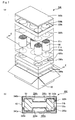
- Fig. 7(a) is an exploded perspective view that schematically shows a mode in which honeycomb structured bodies are being packed in the packing member for honeycomb structured bodies described in Patent Document 1.
- Fig. 7(b) is a cross-sectional view (E-E line cross-sectional view of Fig. 7(a) ) that schematically shows a cross section obtained by cutting the packing member for honeycomb structured bodies shown in Fig. 7 (a) in a direction perpendicular to the bottom face of the recessed portion of the holding member.
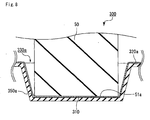
- Fig. 8 is a partially expanded cross-sectional view that schematically shows the neighborhood of the recessed portion of the holding member in the cross-sectional view shown in Fig. 7(b) . As shown in Figs.
- the packing member for honeycomb structured bodies described in Patent Document 1 is configured by a box 60, and a holding member 320a and a holding member 320b to be placed in the box 60.
- a cushion member 340a is placed between the box 60 and the holding member 320a.
- a cushion member 340b is placed between the box 60 and the holding member 320b.
- recessed portions 330a (330b) in each of which are placed the end portions of each honeycomb structured body 50 are formed on the holding member 320a (320b).
- a resin sheet 350a (350b) is affixed onto the surface of the holding member 320a (320b) on which the recessed portions 330a (330b) are formed.
- FIGs. 7(a) and 7(b) the following description will discuss processes in which honeycomb structured bodies are packed by using a conventional packing member 300 for honeycomb structured bodies having this structure.
- two end portions of each honeycomb structured body 50 are placed on each recessed portion 330a of the holding member 320a and each recessed portion 330b of the holding member 320b.
- the resin sheet 350a is inserted between each honeycomb structured body 50 and each recessed portion 330a of the holding member 320a, while being in contact with each end face 51a of the honeycomb structured bodies 50 and each recessed portion 330a of the holding member 320a.
- a resin sheet 350b is inserted between each honeycomb structured body 50 and each recessed portion 330b of the holding member 320b, while being in contact with each end face 51b of the honeycomb structured bodies 50 and each recessed portion 330b of the holding member 320b.
- contained in the box 60 are the holding member 320a and the holding member 320b, in which the honeycomb structured body 50 has been placed, together with the cushion member 340a and the cushion member 340b.
- the packing member 300 for honeycomb structured bodies shown in Fig. 8 the surface 310 of the recessed portion 330a of the holding member 320a and the lower face of the resin sheet 350a are brought in close contact with each other without any gap. Moreover, it is presumed that the upper face of the resin sheet 350a and the end face 51a of the honeycomb structured body 50 are brought in close contact with each other without any gap. That is, it is considered that the packing member 300 for honeycomb structured bodies disclosed in Patent Document 1 has a structure in which the recessed portion 330a of the holding member 320a and the honeycomb structured body 50 are brought in close contact with each other without any gap, with the resin sheet 350a interposed therebetween, and formed into a secured state.
- the recessed portion 330b of the holding member 320b and the honeycomb structured body 50 are brought in close contact with each other, with the resin sheet 350b interposed therebetween without any gap, and formed into a secured state.
- the holding member and the resin sheet made of materials such as cardboard and a resin, are softer than the honeycomb structured body and the peripheral coat layer of the honeycomb structured body that are made of ceramic materials and the like, and have lower strength. Consequently, when such a small stress is continuously applied to the recessed portion of the holding member and the resin sheet, the shape of the recessed portion of the holding member or the resin sheet tends to be gradually changed. It is considered that, as a result, gaps are generated among the recessed portion of the holding member, the resin sheet and the honeycomb structured bodies.
- the recessed portion of the holding member, the resin sheet and the honeycomb structured bodies are brought into an unsecured state when such gaps are generated among the recessed portion of the holding member, the resin sheet and the honeycomb structured bodies. Moreover, upon application of vibration to the packing member for honeycomb structured bodies in this unsecured state of the recessed portion of the holding member, the resin sheet and the honeycomb structured bodies, the stress to be generated in the honeycomb structured bodies increases due to a force transmitted thereto through the resin sheet. It is considered that this increased stress causes frictional damage in the honeycomb structured bodies.
- a packing member for a honeycomb structured body comprises: a holding member provided with a recessed portion having a bottom face and a side face and configured to place a honeycomb structured body on the recessed portion to hold the honeycomb structured body; and a covering member covering at least one portion of the holding member including the recessed portion, wherein the recessed portion of the holding member is provided with a corner portion including: a border portion between the bottom face and the side face; and the neighborhood of the border portion, and the covering member is disposed so as to form a gas layer between the covering member and the corner portion.
- the packing member for honeycomb structured bodies of the invention according to claim 1 makes it possible to prevent the occurrence of deterioration such as breakage and frictional damage of the honeycomb structured bodies.
- the following description will discuss the packing member for honeycomb structured bodies described in claim 1 in detail.
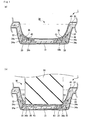
- Fig. 1(a) is a partially expanded cross-sectional view that schematically shows a cross section of the neighborhood of a recessed portion of a holding member taken in a direction perpendicular to the bottom face of the recessed portion about one example of a packing member for honeycomb structured bodies of the present invention.
- Fig. 1(b) is a partially expanded cross-sectional view that schematically shows a mode in which a honeycomb structured body is placed on the recessed portion of the holding member of the packing member for honeycomb structured bodies shown in Fig. 1(a) .
- a packing member 1 for honeycomb structured bodies of the present invention is configured by a holding member 20 having recessed portions 30, each configured by a bottom face 31 and a side face 32, and a covering member 40 that covers the entire holding member 20.
- each recessed portion 30 has a corner portion 33 (portion indicated by an arrow with two heads in Fig. 1(a) ) including the border portion between the bottom face 31 and the side face 32 and the neighborhood of the border portion.
- the corner portion 33 of the recessed portion 30 refers to a portion including a border 34a between the bottom face 31 and the side face 32, a neighborhood 34b of the border 34a in the bottom face 31 and a neighborhood 34c of the border 34a in the side face 32.
- the holding member 20 is sealed inside the covering member 40, with a gas being contained between the holding member 20 and the covering member 40, so that a gas layer 35 is formed between the corner portion 33 and the covering member 40.
- the gas layer 35 is allowed to have such elasticity that it is deformed upon application of a load thereto, but returns to its original shape when the load has been removed. For this reason, when a load is applied to a gas layer forming portion 43 that is one portion of the covering member 40 and forms the gas layer 35, the shape of the gas layer 35 changes with the change in the shape of the gas layer forming portion 43. However, upon removal of the load, the shape of the gas layer 35 returns to its original shape by the elasticity possessed by the gas layer 35 so that the shape of the gas layer forming portion 43 is returned to its original shape in accordance with the change in the shape of the gas layer 35. That is, the gas layer 35 serves as a cushion to absorb the impact (load) such as vibration.
- Fig. 1(b) the following description will discuss a structure in which honeycomb structured bodies are packed in such a packing member for honeycomb structured bodies.
- the gas layer 35 is formed between the covering member 40 and the corner portion 33.
- an outer edge 53 of the end face of the honeycomb structured body 50 and the neighborhood of the outer edge 53 are in contact with the gas layer forming portion 43. That is, the honeycomb structured body 50 is held by the holding member 20 with the gas layer 35 interposed therebetween.
- honeycomb structured bodies 50 are packed in the packing member 1 for honeycomb structured bodies, with each honeycomb structured body 50 being held by the holding member 20 in this manner, even upon application of an impact onto the packing member 1 for honeycomb structured bodies, the impact applied to the packing member 1 for honeycomb fired bodies is absorbed by the gas layer 35. Therefore, the honeycomb structured bodies 50 are free from the application of a strong impact. For this reason, the packing member for honeycomb structured bodies described in claim 1 makes it possible to prevent the occurrence of breakage in the honeycomb structured bodies.
- FIG. 1(b) the following description will discuss a state in which an impact such as vibration is continuously applied to the packing member for honeycomb structured bodies of the present invention in which honeycomb structured bodies have been packed.
- a small stress is continuously applied to: the outer edge 53 of the end face of each honeycomb structured body 50 and the neighborhood of the outer edge 53; and the gas layer forming portion 43 that is in contact with the outer edge 53 and the neighborhood of the outer edge 53.
- the shape of the gas layer forming portion 43 is deformed to cause a gap between: the gas layer forming portion 43; and the outer edge 53 of the end face of each honeycomb structured body 50 and the neighborhood of the outer edge 53.
- the gas layer 35 located between the covering member 40 (gas layer forming portion 43) and the corner portion 33 has an elasticity, the gas layer forming portion 43 is allowed to receive a pressing force in a direction toward the outer edge 53 of the end face of each honeycomb structured body 50 and the neighborhood of the outer edge 53 by the gas layer 35 so that presumably, the shape is returned to its original shape.
- the packing member for honeycomb structured bodies described in claim 1 makes it possible to prevent the occurrence of frictional damage in the honeycomb structured bodies.
- the packing member for honeycomb structured bodies of the invention described in claim 1 therefore makes it possible to provide a packing member for honeycomb structured bodies that can prevent the occurrence of deterioration, such as breakage and frictional damage of the honeycomb structured bodies.
- the covering member is made of a resin.
- the covering member is less susceptible to rupture or the like. For this reason, the packing member for honeycomb structured bodies described in claim 2 is less prone to leakage of the gas from the gas layer, thereby making it possible to maintain the gas layer with elasticity.
- the covering member covers the entire portion of the holding member.
- the holding member is sealed by the covering member.
- ceramic powder adhering onto the surface of the covering member is hardly allowed to adhere to the holding member, causing no fouling in the holding member due to ceramic powder.
- the covering member may be replaced without the necessity of washing or the like of the holding member, so that the holding member can be reused. Therefore, since the packing member for honeycomb structured bodies described in claim 4 is capable of recycling the holding member, it is possible to provide a packing member for honeycomb structured bodies that can reduce the environmental load and also cut transportation costs and the like.
- the covering member has a bag shape with one opening portion or a tube shape with two opening portions before the holding member is sealed by the covering member, and by sealing the opening portion, the holding member is sealed by the covering member.
- the opening portion is sealed by thermal compression bonding.
- a gas layer is formed between the covering member and the corner portion, that is, between the covering member and the holding member.
- the holding member and the covering member are sealed with each other through thermal compression bonding.
- the holding member and the covering member are secured to each other.
- a gas layer is formed between the corner portion and the covering member. Therefore, in the packing member for honeycomb structured bodies described in claim 7, it is possible to provide a packing member for honeycomb structured bodies that is highly effective to prevent the occurrence of deterioration in the honeycomb structured bodies.
- the holding member and the covering member are secured to each other by a securing member.
- the holding member and the covering member are secured to each other by thermal compression bonding.
- a gas layer is formed between the covering member and the corner portion, that is, between the covering member and the holding member.
- the holding member and the covering member are firmly sealed with each other through thermal compression bonding.
- the packing member for honeycomb structured bodies is less susceptible to leakage of the gas from the gas layer formed between the holding member and the covering member, through a gap between the holding member and the covering member. Therefore, it is possible to maintain the gas layer with elasticity. Therefore, the resulting packing member for honeycomb structured bodies described in claim 9 becomes highly effective to prevent the occurrence of deterioration in the honeycomb structured bodies.
- the holding member is provided with a vent that allows a gas to come in and go out of the gas layer, and the vent is capable of being opened and closed.
- honeycomb structured bodies after honeycomb structured bodies have been held on the holding member with the gas layer interposed therebetween by using a packing member for honeycomb structured bodies, for example, through a process in which, after the gas layer has been further filled with a gas through the vent, the vent is closed by a plugging member, or a process in which, after the gas has been sucked from the gas layer through the vent, the vent is closed by a plugging member, the elasticity of the gas layer can be adjusted on demand.
- the elasticity of the gas layer formed between the covering member and the corner portion can be adjusted so as to allow the gas layer to effectively absorb the impact. For this reason, even in the case when honeycomb structured bodies are packed in the packing member for honeycomb structured bodies and when an impact is applied to the packing member for honeycomb structured bodies, the impact to be applied to the honeycomb structured bodies can be effectively absorbed by the gas layer so that the occurrence of breakage in the honeycomb structured bodies can be prevented more effectively.
- the elasticity of the gas layer formed between the covering member and the corner portion can be adjusted so as to effectively prevent the occurrence of a gap between the gas layer forming portion and the honeycomb structured body. For this reason, even in the case when honeycomb structured bodies are packed in the packing member for honeycomb structured bodies and when an impact such as vibration is continuously applied thereto, the shape of the gas layer forming portion is readily returned to its original shape by the elasticity of the gas layer. Therefore, it is possible to more effectively prevent the occurrence of a gap between: the gas layer forming portion; and the outer edge portion of the end face of the honeycomb structured body and the neighborhood of the outer edge portion. Since it is possible to prevent a stress generated in the honeycomb structured bodies by the stress transmitted thereto through the covering member from increasing, it is consequently possible to more efficiently prevent the occurrence of frictional damage in the honeycomb structured bodies.
- the packing member for honeycomb structured bodies of the invention described in claim 10 makes it possible to provide a packing member for honeycomb structured bodies that is highly effective to prevent the occurrence of deterioration, such as breakage and frictional damage, in the honeycomb structured bodies.
- the vent is disposed on the side face or the bottom face of the recessed portion.
- the invention described in claim 12 is a method for transporting a honeycomb structured body, by using a packing member for a honeycomb structured body, the method comprising: placing a honeycomb structured body on the recessed portion of the holding member of the packing member for a honeycomb structured body according to any of claims 1 to 11; packing the honeycomb structured body with the packing member for a honeycomb structured body; and transporting the packing member for a honeycomb structured body in which the honeycomb structured body has been packed.
- honeycomb structured bodies are packed by using a packing member for honeycomb structured bodies that is highly effective to prevent the occurrence of deterioration, such as breakage and frictional damage, in the honeycomb structured bodies and then transported. Therefore, even upon application of an impact such as vibration to the honeycomb structured bodies, it is possible to transport the honeycomb structured bodies without any occurrence of deterioration in the honeycomb structured bodies.
- the honeycomb structured body is packed by the packing member for a honeycomb structured body
- a packing member for honeycomb structured bodies which is highly effective to prevent the occurrence of deterioration, such as breakage and frictional damage, in the honeycomb structured bodies, is used, and the upper end portion and lower end portion of each of the honeycomb structured bodies are placed on the recessed portions of the holding member, so that the honeycomb structured bodies are packed by the packing member for honeycomb structured bodies and then transported. Therefore, even upon application of an impact such as vibration to the honeycomb structured bodies, it is possible to transport the honeycomb structured bodies without any occurrence of deterioration in the honeycomb structured bodies.
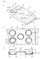
- Fig. 2 (a) is a perspective view that schematically shows one example of a packing member for honeycomb structured bodies of the present invention
- Fig. 2 (b) is a plan view of the packing member for honeycomb structured bodies shown in Fig. 2(a).
- Fig. 2 (c) is a cross-sectional view that schematically shows a cross section obtained by cutting the packing member for honeycomb structured bodies shown in Fig.
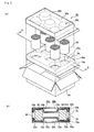
- FIG. 2(a) is an exploded perspective view that schematically shows a mode in which honeycomb structured bodies are being packed in the packing member for honeycomb structured bodies of the present invention shown in Fig. 2 (a) , and further contained in a box.
- Fig. 3(b) is a cross-sectional view (B-B line cross-sectional view of Fig. 3(a) ) that schematically shows a cross section obtained by cutting the box containing the packing member for honeycomb structured bodies shown in Fig. 3 (a) in a direction perpendicular to the bottom face of the recessed portion of the holding member.
- the packing member 1 for honeycomb structured bodies has a structure in which the entire holding member 20 is covered with a covering member 40 having a bag shape. Moreover, a sealing portion 42 is formed near an opening portion 41 of the covering member 40 that entirely covers the holding member 20, so that the opening portion 41 of the covering member 40 is sealed. That is, in the packing member 1 for honeycomb structured bodies, the holding member 20 is sealed inside the covering member 40.
- the holding member 20 is a plate-shaped member made of a resin, cardboard or the like. As shown in Figs. 2(a), 2(b) and 2(c) , recessed portions 30 are formed on one face of the holding member 20. Each recessed portion 30 of the holding member 20 includes a bottom face 31 and a side face 32 that is disposed perpendicularly to the periphery 37 of the bottom face 31.
- the recessed portion 30 has a corner portion 33 (portion indicated by a two-directional arrow in Fig. 2(c) ) including: the border portion between the bottom face 31 and the side face 32; and the neighborhood of the border portion.
- the shape of the recessed portion 30 is virtually the same as one portion of the outer shape of a honeycomb structured body to be placed on the recessed portion 30.
- the covering member 40 which is made of a resin, has an opening portion 41, and is formed into a bag shape that can cover the entire holding member 20. Moreover, the opening portion 41 is sealed by thermal compression bonding so that the sealing portion 42 as shown in Figs. 2 (a), 2 (b) and 2 (c) can be formed.
- the detailed structure of the packing member for honeycomb structured bodies, made of the respective members described above, is the same as the structure described by reference to Fig. 1(a) . That is, in the packing member for honeycomb structured bodies of the present embodiment, the covering member 40 is placed in such a manner that a gas layer 35 is formed between the covering member 40 and each corner portion 33.
- each honeycomb structured body 50 is placed on a recessed portion 30a of a holding member 20a of a packing member 1a for honeycomb structured bodies with a covering member 40a interposed therebetween.
- the upper end portion of the honeycomb structured body 50 is placed on a recessed portion 30b of a holding member 20b of a packing member 1b for honeycomb structured bodies with a covering member 40b interposed therebetween.
- each honeycomb structured body 50 is packed in a manner so as to be sandwiched from both upward and downward directions between the packing members 1a and 1b for honeycomb structured bodies, and the packing members 1a and 1b for honeycomb structured bodies are contained in a box 60 with the honeycomb structured bodies 50 sandwiched therebetween.
- the detailed structure of the packing member for honeycomb structured bodies in which honeycomb structured bodies are packed is the same as the structure described by reference to Fig. 1(b) . That is, in the case when honeycomb structured bodies are packed in the packing member for honeycomb structured bodies of the present embodiment, as shown in Fig. 3(b) , gas layers 35 (35a, 35b) are formed between covering members 40 (40a, 40b) and corner portions 33 (33a, 33b). Moreover, honeycomb structured bodies 50 are held on the holding members 20 (20a, 20b) with the gas layers 35 (35a, 35b) interposed therebetween, in a state where the honeycomb structured bodies 50 are brought in contact with gas layer forming portions 43 (see Fig. 1(b) ).
- a plate-shaped member made of a resin, cardboard or the like is processed so that recessed portions, each having virtually the same shape of the end portion of each honeycomb structured body, are formed on one face of the plate-shaped member; thus, a holding member is manufactured.
- a covering member which is larger than the outer shape of the holding member and has a bag shape with one opening portion, is prepared. And then, the entire holding member is covered with the covering member.
- the elasticity of the gas layer is adjusted by filling the inside of the covering member with a gas so as to form a gas layer between the covering member and the corner portion of the holding member, or by sucking a gas from the inside of the covering member.
- the packing member for honeycomb structured bodies of the present embodiment is manufactured by the above-mentioned processes.
- the following description will discuss a method for transporting honeycomb structured bodies by using the packing member for honeycomb structured bodies of the present embodiment.
- two of the packing members for honeycomb structured bodies of the present embodiment are prepared.
- each of lower end portions of honeycomb structured bodies is placed on each of the recessed portions of the holding member of the packing member for honeycomb structured bodies on the lower side with the covering member interposed therebetween.
- each of upper end portions of the honeycomb structured bodies is placed on each of the recessed portions of the holding member of the packing member for honeycomb structured bodies on the upper side, with the covering member interposed therebetween, so that the upper packing member for honeycomb structured bodies is mounted on the honeycomb structured bodies.
- honeycomb structured bodies are packed in a manner so as to be sandwiched between two packing members for honeycomb structured bodies from both upward and downward directions.
- the embodiment in which honeycomb structured bodies are packed in the packing member for honeycomb structured bodies of the present embodiment is the same as the embodiment described by reference to Figs. 3(a) and 3(b) .
- a box having virtually the same inside dimension as that of the outer shape of the packing member for honeycomb structured bodies in which honeycomb structured bodies are packed is prepared. Then, the packing member for honeycomb structured bodies in which the honeycomb structured bodies have been packed is contained in the box, with the upper end portions of the honeycomb structured bodies facing up and the lower end portions of the honeycomb structured bodies facing down in the box, and the lid of the box is closed.
- honeycomb structured bodies are transported by using the packing member for honeycomb structured bodies of the present embodiment.
- the gas layer formed between the covering member and the corner portion has an elasticity to return to its original shape; therefore, even when the shape of the gas layer forming portion is changed, it can be returned to its original shape.
- the shape of a gas layer forming portion is changed.
- the gas layer, formed between the covering member and the corner portion has elasticity, a gap hardly appears between the gas layer forming portion and each honeycomb structured body. For this reason, since the recessed portion of the holding member, the covering member and each honeycomb structured body are kept in a secured state. Therefore, a stress generated in the honeycomb structured body is hardly increased due to the stress transmitted thereto through the covering member. Therefore, by using the packing member for honeycomb structured bodies of the present embodiment, it is possible to prevent frictional damage from occurring in the honeycomb structured bodies.
- the covering member is made of a resin. Therefore, even when an impact such as vibration is continuously applied to the packing member for honeycomb structured bodies, the covering member is less susceptible to a rupture or the like. For this reason, the packing member for honeycomb structured bodies of the present embodiment is less prone to leakage of the gas from the gas layer, thereby making it possible to maintain the gas layer with elasticity.
- a gas layer is formed between the covering member and the corner portion, that is, between the covering member and the holding member. Moreover, the holding member and the covering member are firmly sealed by thermal compression bonding. For this reason, the packing member for honeycomb structured bodies of the present embodiment is less susceptible to leakage of the gas in the gas layer from the opening portion, thereby making it possible to maintain the gas layer with elasticity.
- the covering member covers the entire holding member so that the holding member is sealed by the covering member; therefore, ceramic powder adhering onto the surface of the covering member is hardly allowed to adhere to the holding member, causing no fouling in the holding member due to ceramic powder. Moreover, even in the case when ceramic power has adhered to the covering member, only the covering member may be replaced so that the holding member can be re-used. Therefore, since the packing member for honeycomb structured bodies of the present embodiment is capable of recycling the holding member, it is possible to provide a packing member for honeycomb structured bodies that can reduce the environmental load and also cut transportation costs and the like.
- the honeycomb structured bodies are packed by the packing member for honeycomb structured bodies of the present embodiment that is highly effective to prevent the occurrence of deterioration, such as breakage and frictional damage of the honeycomb structured bodies, and then transported. Therefore, even when an impact such as vibration is applied to the honeycomb structured bodies, it is possible to transport the honeycomb structured bodies without any occurrence of deterioration in the honeycomb structured bodies.
- a plate member made of a polypropylene resin having a thickness of 1 mm was processed into a thickness of 0.2 mm, and a holding member having an outer shape of 580 mm in width x 380 mm in length x 40 mm in height, with five recessed portions, each having a size of 150 mm in diameter of the bottom face x 155 mm in aperture diameter was formed on one face thereof.
- a covering member having a bag shape with one opening portion which was made of a resin bag composed of polyethylene and had a size of 800 mm in length (depth) x 382 mm in aperture diameter x 0.04 mm in thickness, was prepared. Moreover, the holding member, manufactured in the process (1), was put into the resin bag from the opening portion. Then, the entire holding member was covered with the resin bag so that the holding member covered with the covering member was manufactured.
- the resin bag was filled with air through the opening portion of the covering member by using an air pump.
- the neighborhood of the opening portion of the covering member was sealed by thermal compression bonding so that a sealed portion was formed; thus, the holding member was sealed by the covering member.
- Manufactured through the above-mentioned processes was a packing member for honeycomb structured bodies in which the covering member was placed so as to form a gas layer between the covering member and each of the corner portions.
- Honeycomb structured bodies were packed by the packing member for honeycomb structured bodies manufactured by the aforementioned processes, and vibration tests was carried out so that evaluation was made as to whether or not any deterioration occurred in the honeycomb structured bodies.
- a round pillar-shaped honeycomb structured body having a size of 143.8 mm in diameter x 150 mm in length manufactured by a conventionally known method was used as the honeycomb structured body to be packed.
- a vibration testing device 80 is configured by a mounting base 81 on which a box 60 containing a packing member for honeycomb structured bodies that has packed honeycomb structured bodies is placed, and a vibration unit 83 that functions so as to connect the mounting base 81 to a base plate 82, and also generates vibrations and applies the vibrations to the mounting base 81.
- a mounting member 84 used for placing the box 60 on the mounting base 81 in a stable state is attached to the mounting base 81.
- a vibration meter 85 (Digivibro Model-1332A, made by Showa Sokki Corporation), used for recording vibrations in horizontal and vertical directions generated by the vibration unit 83 as the acceleration, is attached to the vibration unit 83.
- the testing method using this vibration testing device is described below.
- 5 pieces of honeycomb structured bodies were prepared, and the two end portions of each honeycomb structured body were placed on the recessed portions of the holding members of two packing members for honeycomb structured bodies manufactured in Example 1; thus, the honeycomb structured bodies were packed.
- the packing members for honeycomb structured bodies which had packed the honeycomb structured bodies were contained in a box having outer dimensions of 600 mm in width x 400 mm in length x 180 mm in height, with the upper end portion of each honeycomb structured body facing up and the lower end portion of each honeycomb structured body facing down in the box.
- the box 60 containing the packing members for honeycomb structured bodies was placed on the mounting base 81, and by vibrating the vibration unit 83 under conditions of an acceleration of 4.9 m/s 2 for 24 hours so that vibrations were applied to the box 60.
- the packing members for honeycomb structured bodies were taken out of the box 60, and each of the honeycomb structured bodies packed in the packing members for honeycomb structured bodies was visually examined as to whether or not any deterioration such as breakage (chipping, cracking, and the like) and frictional damage (flaking of ceramic powder and the like) occurred therein.
- Example 1 The same processes as those of Example 1 were carried out to manufacture a packing member for honeycomb structured bodies, except that the material for the covering member was changed as shown in Table 1.
- Example 1 The same processes as those of Example 1 were carried out to manufacture a packing member for honeycomb structured bodies, except that a plate member made of cardboard having a thickness of 7 mm was processed to form the holding member in the process (1) in Example 1.
- a packing member for honeycomb structured bodies was manufactures by affixing a resin sheet made of polyethylene having 600 mm in width x 400 mm in length x 0.04 mm in thickness onto a face with recessed portions formed thereon of the holding member manufactured in the process (1) in Example 1.
- a packing member for honeycomb structured bodies was manufactured in the same manner as in Comparative Example 1, except that the material for the holding member was changed to the same material, cardboard, used in Example 4. In the packing members for honeycomb structured bodies manufactured in Comparative Examples 1 and 2, no gas layer was formed between the covering member and the corner portion.
- Vibration tests were carried out in the same manner as in Example 1 on each of the packing members for honeycomb structured bodies manufactured in Examples 2 to 4 and Comparative Examples 1 and 2, and evaluation was made as to whether or not any deterioration occurred in the honeycomb structured bodies.
- Honeycomb structured bodies were directly placed on the holding member manufactured in the process (1) in Example 1 without using the covering member, and the vibration tests were carried out in the same manner as in Example 1 so that evaluation was made as to whether or not any deterioration occurred in the honeycomb structured bodies.
- Table 1 shows the materials and the like for the holding members and the covering members in the Examples and Comparative Examples, as well as the presence of a gas layer and the presence of deterioration in the honeycomb structured bodies, together with the results of Example 1.
- the weight of generated ceramic powder was measured. The results of the measurements are also shown in Table 1.
- a covering member prior to the sealing of the holding member to be used upon manufacturing the packing member for honeycomb structured bodies has a tube shape with two opening portions.
- the packing member for honeycomb structured bodies of the present embodiment has the same structure as that of the first embodiment, except that sealing portions are formed on the neighborhoods of the respective opening portions of the covering member by thermal compression bonding or the like and that the holding member is sealed by sealing each of the opening portions.
- the method for transporting honeycomb structured bodies of the present embodiment is the same as the method for transporting honeycomb structured bodies of the first embodiment, except that the packing member for honeycomb structured bodies to be used is different from each other.
- the above-mentioned second embodiment also exerts the effects (1) to (6) described in the first embodiment.
- Vibration tests were carried out in the same manner as in Example 1 on the packing member for honeycomb structured bodies manufactured in Example 5, and evaluation was made as to whether or not any deterioration occurred in the honeycomb structured bodies. As a result, neither breakage nor frictional damage occurred in the honeycomb structured bodies after the vibration tests. Moreover, when the surface of the holding member was observed with the covering member removed therefrom, no fouling due to ceramic powder occurred.
- the packing member for honeycomb structured bodies of the second embodiment also made it possible to prevent the occurrence of deterioration in the honeycomb structured bodies. Moreover, fouling of the holding member due to ceramic powder was also prevented.
- Fig. 5 (a) is a perspective view that schematically shows another example of a packing member for honeycomb structured bodies of the present invention
- Fig. 5(b) is a plan view of the packing member for honeycomb structured bodies shown in Fig. 5(a)
- Fig. 5(c) is a cross-sectional view that schematically shows a cross section obtained by cutting the packing member for honeycomb structured bodies shown in Fig. 5(a) in a direction perpendicular to the bottom face of a recessed portion of a holding member (C-C line cross-sectional view of Figs.
- Figs. 5 (a) and 5(b) show a state in which one portion of a covering member is cut out so as to show the recessed portion of the holding member.
- a face on which the recessed portions of the holding member are formed in a packing member for honeycomb structured bodies is referred to as the upper face of the holding member (upper face of a packing member for honeycomb structured bodies), a face opposite to the upper face is referred to as the lower face of the holding member (lower face of the packing member for honeycomb structured bodies), and a face perpendicular to the upper face is referred to as the side face of the holding member (side face of the packing member for honeycomb structured bodies).
- a packing member 11 for honeycomb structured bodies is configured by a holding member 120 on which recessed portions are formed, and a covering member 140 made of a resin sheet that covers the entire upper face of the holding member 120 and most of the side face thereof.
- the covering member 140 is pressed onto the side face of the holding member 120 by a securing member 160 such as an adhesive tape so that the covering member 140 and the holding member 120 are secured to each other.
- the recessed portion 130 of the holding member 120 is provided with a corner portion 133 including: a border portion between a bottom face 131 and a side face 132; and the neighborhood of the border portion. Moreover, the entire upper face and most of the side face of the holding member 120 are covered with the covering member 140, and the holding member 120 and the covering member 140 are mutually secured by the securing member 160 so that a gas layer 135 is formed between the corner portion 133 and the covering member 140.
- the other structures of the packing member for honeycomb structured bodies in the present embodiment are the same as those of the first embodiment; therefore, the detailed description thereof will be omitted.
- a plate-shaped member such as a resin and cardboard, is processed to manufacture a holding member.
- a sheet-shaped covering member having a size capable of covering the entire upper face and most of the side face of the holding member is prepared, and by covering the entire upper face and most of the side face of the holding member with this covering member, the holding member covered with the covering member is manufactured.
- the covering member is pressed onto the side face of the holding member by using a securing member such as an adhesive tape so that the covering member and the holding member are secured to each other.
- a securing member such as an adhesive tape
- the method for transporting honeycomb structured bodies of the present embodiment is the same as the method for transporting honeycomb structured bodies of the first embodiment except that the packing member for honeycomb structured bodies is different.
- the above-mentioned third embodiment also makes it possible to exert the effects (1) to (3) and (6) described in the first embodiment.
- a holding member was manufactured by using the same process (1) in Example 1.
- a sheet-shaped covering member which was made of a polyethylene resin sheet having a size of 800 mm in width x 600 mm in length x 0.04 mm in thickness, was prepared. Moreover, by covering the entire upper face and most of the side face of the holding member manufactured in the process (1), a holding member covered with the covering member was manufactured.
- a packing member for honeycomb structured bodies was manufactured in the same manner as in Example 6, except that in the process (1) in Example 6, a plate-shaped member made of cardboard having a thickness of 7 mm was processed to manufacture a holding member.
- Vibration tests were carried out in the same manner as in Example 1 on each of the packing members for honeycomb structured bodies manufactured in Examples 6 and 7, and evaluation was made as to whether or not any deterioration occurred in the honeycomb structured bodies. As a result, neither breakage nor frictional damage occurred in the honeycomb structured bodies after the vibration tests.
- the packing member for honeycomb structured bodies of the third embodiment also made it possible to prevent the occurrence of deterioration in the honeycomb structured bodies.
- the packing member for honeycomb structured bodies of the present embodiment has the same structure as that of the third embodiment except that the covering member in the third embodiment and the side face of the holding member are secured to each other through thermal compression bonding. That is, in the same manner as in the first embodiment, each of the recessed portions of the holding member has a corner portion including: a border portion between the bottom face and the side face; and the neighborhood of the border portion.
- the entire upper face and most of the side face of the holding member are covered with the covering member, and the holding member and the covering member are secured to each other through thermal compression bonding so that a gas layer is formed between the corner portion and the covering member.
- the method for transporting honeycomb structured bodies of the present embodiment is the same as the method for transporting honeycomb structured bodies of the first embodiment except that the packing member for honeycomb structured bodies is different.
- the above-mentioned fourth embodiment also makes it possible to exert the effects (1) to (3) and (6) described in the first embodiment.
- the present embodiment can also exert the following effects. (7) A gas layer is formed between the covering member and the corner portion, that is, between the covering member and the holding member. Moreover, the holding member and the covering member are firmly sealed by thermal compression bonding. For this reason, the packing member for honeycomb structured bodies of the present embodiment is less susceptible to leakage of the gas in the gas layer through a gap between the holding member and the covering member, and it is possible to maintain the gas layer with elasticity.
- a packing member for honeycomb structured bodies was manufactured in the same manner as in Example 6, except that in the process (3) in Example 6, the holding member and the covering member were secured to each other on the side face of the holding member through thermal compression bonding.
- Vibration tests were carried out in the same manner as in Example 1 on the packing member for honeycomb structured bodies manufactured in Example 8, and evaluation was made as to whether or not any deterioration occurred in the honeycomb structured bodies. As a result, neither breakage nor frictional damage occurred in the honeycomb structured bodies after the vibration tests.
- the packing member for honeycomb structured bodies of the fourth embodiment also made it possible to prevent the occurrence of deterioration in the honeycomb structured bodies.
- Fig. 6 (a) is a perspective view that schematically shows still another example of a packing member for honeycomb structured bodies of the present invention
- Fig. 6(b) is a plan view of the packing member for honeycomb structured bodies shown in Fig. 6(a)
- Fig. 6(c) is a cross-sectional view that schematically shows a cross section obtained by cutting the packing member for honeycomb structured bodies shown in Fig. 6(a) in a direction perpendicular to the bottom face of a recessed portion of a holding member (D-D line cross-sectional view of Figs. 6 (a) and 6(b) ).
- Figs. 6 (a) and 6 (b) show a state in which one portion of a covering member is cut out so as to show the recessed portion of the holding member.
- a packing member for honeycomb structured bodies 21, shown in Figs. 6(a), 6(b) and 6(c) is provided with each of recessed portions 230 of a holding member 220 that has a corner portion 233 including: a border portion between a bottom face 231 and a side face 232; and the neighborhood of the border portion.
- the entire upper face and most of the side face of the holding member 220 is covered with a covering member 240, and the holding member 220 and the covering member 240 are secured to each other by a securing member 260 so that a gas layer 235 is formed between the corner portion 233 and the covering member 240.
- a vent 290 is formed on the corner portion 233 on the side face 231 side, by penetrating the holding member 220. For this reason, a gas is allowed to come into and go out from the gas layer 235 through the vent 290. Moreover, the vent 290 is closed by a plugging member 291 such as a rubber plug so that the vent 290 can be opened and closed.
- the packing member for honeycomb structured bodies of the present embodiment after honeycomb structured bodies have been held on the holding member with the gas layer interposed therebetween, the gas layer is further filled with the gas through the vent by using an air pump or the like, and the vent is then closed by a plugging member such as a rubber plug, or after the gas has been sucked from the gas layer through the vent by using an air pump or the like, the vent is closed by a plugging member such as a rubber plug; thus, the elasticity of the gas layer can be adjusted on demand.
- the other structures of the packing member for honeycomb structured bodies in the present embodiment are the same as those of the third embodiment; therefore, the detailed description thereof will be omitted.
- the method for transporting honeycomb structured bodies of the present embodiment is the same as the method for transporting honeycomb structured bodies of the first embodiment except that the packing member for honeycomb structured bodies to be used is different.
- the present embodiment also makes it possible to exert the effects (1) to (3) and (6) described in the first embodiment. Moreover, the present embodiment can also exert the following effects.
- the packing member for honeycomb structured bodies of the present embodiment makes it possible to adjust the elasticity of the gas layer formed between the covering member and the corner portion so as to allow the gas layer to more effectively absorb the impact. For this reason, in the case when honeycomb structured bodies are packed in the packing member for honeycomb structured bodies of the present embodiment and when an impact is applied to the packing member for honeycomb structured bodies, the impact to be applied to the honeycomb structured bodies can be effectively absorbed by the gas layer so that the occurrence of breakage in the honeycomb structured bodies can be prevented more effectively.
- honeycomb structured bodies by taking into account the number, the outer shape and the like of honeycomb structured bodies to be packed, it is possible to adjust the elasticity of the gas layer formed between the covering member and the corner portion so as to more effectively prevent the occurrence of a gap between the gas layer forming portion and the honeycomb structured bodies. For this reason, even in the case when honeycomb structured bodies are packed in the packing member for honeycomb structured bodies of the present embodiment and when an impact such as vibration is continuously applied thereto, the shape of the gas layer forming portion is readily returned to its original shape due to the elasticity of the gas layer. Therefore, it is possible to more effectively prevent the occurrence of a gap between: the covering member; and the outer edge portion of the end face of the honeycomb structured body and the neighborhood of the outer edge portion. Since it is possible to prevent a stress generated in the honeycomb structured bodies by the stress transmitted thereto through the covering member from increasing, it is consequently possible to more efficiently prevent the occurrence of frictional damage in the honeycomb structured bodies.
- a packing member for honeycomb structured bodies was manufactured in the same manner as in Example 6, except that a through hole (diameter: 3 mm) was formed on the side face of each recessed portion of the holding member used in Example 6 to provide a vent therein so that a holding member with the vent was manufactured.
- the gas layer was filled with air through the vent by using an air pump. Thereafter, the elasticity of the gas layer was adjusted by closing the vent with a plugging member made of a rubber plug.
- a packing member for honeycomb structured bodies was manufactured in the same manner as in Example 9, except that, instead of forming the vent through the side face of each recessed portion of the holding member, a vent was formed on the bottom face of each recessed portion to manufacture a holding member with the vent.
- Vibration tests were carried out in the same manner as in Example 1 on each of the packing members for honeycomb structured bodies manufactured in Examples 9 and 10, and evaluation was made as to whether or not any deterioration occurred in the honeycomb structured bodies. As a result, neither breakage nor frictional damage occurred in the honeycomb structured bodies after the vibration tests.
- the packing member for honeycomb structured bodies of the fifth embodiment also made it possible to prevent the occurrence of deterioration in the honeycomb structured bodies.
- the holding member which is one component of the packing member for honeycomb structured bodies of the present invention, is desirably made of a material which has such strength that it is not deformed in its shape by an impact applied from the outside in processes such as packing and transportation of the honeycomb structured bodies and that it is not deformed in its shape because it cannot fully support the weight of the honeycomb structured bodies placed thereon.
- the material include; resins such as polyethylene terephthalate (PET), polyvinyl chloride (PVC), polycarbonate (PC), acryl, polyamide (PA), acrylonitrile butadiene styrene copolymer (ABS), and foamed polystyrene; wood; metal; and the like.
- the packing member for honeycomb structured bodies of the present invention may be formed by combining any of these materials. Specific examples of such an embodiment include a structure in which the holding member is made of cardboard, with the side face of each recessed portion of the holding member being made of foamed polystyrene.
- examples of the method for manufacturing the holding member having recessed portions in the manufacturing process for the holding member include a resin molding method, such as a vacuum molding process, an injection molding process, and a press molding process, in the case when the material for the holding member is resin.
- a resin molding method such as a vacuum molding process, an injection molding process, and a press molding process
- the material for the holding member is resin.
- a method for carrying out machining and assembling processes through punching, cutting or the like may be used.
- the thickness of the holding member is desirably set in a range from 0.1 mm to 0.5 mm, for example, in the case when the material for the holding member is polypropylene.
- the thickness of less than 0.1 mm makes the strength of the holding member insufficient, with the result that during processes such as packing and transportation of honeycomb structured bodies, the shape of the holding member tends to be deformed by an impact applied from the outside, or the shape of the holding member might be deformed due to a failure to fully support the weight of the honeycomb structured bodies placed thereon.
- the thickness of more than 0.5 mm makes it difficult to process the holding member into a predetermined shape.
- the outer shape of the holding member is not particularly limited since it is determined by the size of a box to contain honeycomb structured bodies packed in the packing member for honeycomb structured bodies, and it is desirably formed so that the distance between the side face of the box and the side face of the packing member for honeycomb structured bodies is set to 15 mm or less. In the case when the distance is more than 15 mm, since the stress exerted between the box and the packing member for honeycomb structured bodies is increased during processes such as packing and transportation of honeycomb structured bodies, with the result that deterioration might occur in the honeycomb structured bodies.
- the distance between the lower face of the upper side of the packing member for honeycomb structured bodies and the upper face of the box is desirably set to 15 mm or less.
- each recessed portion of the holding member is not particularly limited since it is determined by the size, the portion or the like of honeycomb structured bodies to be placed on the recessed portion of the holding member, and, for example, in the case when the end portion of each honeycomb structured body is placed on the recessed portion of the holding member, the diameter of the bottom face of the recessed portion is desirably set to 5 mm to 10 mm longer than the diameter (outer diameter) of the end face of the honeycomb structured body to be placed thereon.
- This makes it possible to easily form a gas layer between the covering member and the corner portion of the holding member, and consequently to provide a packing member for honeycomb structured bodies that can more effectively prevent the occurrence of deterioration in the honeycomb structured bodies.
- the aperture diameter of the recessed portion is desirably made larger than the diameter of the bottom face in the recessed portion of the holding member, and it is, for example, set to 2 to 10 mm longer than the diameter of the bottom face of the recessed portion.
- the height of the recessed portion is desirably set to a length corresponding to 1/2 to 1/6 of the length of the honeycomb structured body to be placed thereon. This allows the holding member to more surely hold the honeycomb structured body, and makes it possible to provide a packing member for honeycomb structured bodies that can more effectively prevent the occurrence of deterioration in the honeycomb structured bodies.
- the number of the recessed portions of the holding member may be altered on demand, depending on the sizes of the holding member and the honeycomb structured bodies to be packed.
- the number of the recessed portions of the holding member on which the honeycomb structured bodies are placed is desirably set to 4 to 6.
- the number of less than 4 makes the number of honeycomb structured bodies to be transported per one packing member for honeycomb structured bodies too small, resulting in high transporting costs.
- the number of more than 6 makes the number of honeycomb structured bodies to be placed per one packing member for honeycomb structured bodies too great to cause insufficient strength in the holding member, with the result that the holding member fails to fully support the weight of the honeycomb structured bodies placed thereon to cause the shape of the holding member to be deformed.
- the covering member which is one component of the packing member for honeycomb structured bodies of the present invention, desirably has a high gas barrier property so that the covering member is placed, with a gas layer being interposed between the corner portion and the covering member, and also desirably has elasticity. Moreover, the covering member is desirably made less susceptible to adhesion of ceramic powder. And the covering members are desirably thermal compression bonded to each other, or the covering member is desirably thermal compression bonded to the holding member.
- resins such as polyethylene (PE), polyvinyl chloride (PVC), and polypropylene (PP)
- specific examples of the material include resins such as polyvinylidene chloride (PVDC), ethylene vinyl acetate copolymer (EVA), polyethylene terephthalate (PET), and polyamide (PA).
- PVDC polyvinylidene chloride
- EVA ethylene vinyl acetate copolymer
- PET polyethylene terephthalate
- PA polyamide
- the thickness of the covering member is desirably set in a range from 0.01 mm to 0.2 mm, for example, in the case when the material for the covering member is polyethylene.
- the thickness of less than 0.01 mm makes the thickness of the covering member too thin, with the result that, during processes such as packing and transportation of honeycomb structured bodies, rupturing or the like tends to occur in the covering member.
- the thickness of more than 0.2 mm causes a reduction in the flexibility of the covering member, making it difficult to place the covering member in a manner so as to form the gas layer between the covering member and the corner portion.
- a sheet-shaped covering member (resin sheet) is used as the covering member for forming the packing member for honeycomb structured bodies of the present invention
- its size, shape and the like thereof are not particularly limited, as long as it can cover at least the recessed portions of the holding member.
- a covering member having a size that can cover virtually the entire faces of the upper face and the side face of the holding member there may be employed: a covering member having a size that can cover virtually the entire face of the upper face of the holding member; and a covering member having a size that can cover virtually the entire faces of the upper face, the side face and the lower face of the holding member, that is, the entire portions of the holding member.
- a method for sealing the opening portion of the covering member in the sealing process used upon manufacturing the packing member for honeycomb structured bodies of the present invention in addition to the above-mentioned method using thermal compression bonding, for example, a method for sealing the opening portion with an adhesive agent and a method for binding the covering members near the opening portion with each other may be used.
- the sealing process by thermal compression bonding is more desirably used. Since the thermal compression bonding makes it possible to firmly seal the opening portion, the sealing process can be easily carried out, without leakage of the gas from the gas layer.
- the covering member to be used in the sealing process may be prepared as a sheet-shaped covering member.
- a sealing method is proposed in which two sheets of covering members are superposed on one another, the entire holding member is covered with the covering members, with the holding member being sandwiched therebetween, and the two sheets of the covering members are mutually sealed with each other on the entire peripheral edge portion thereof by using thermal compression bonding or the like so that the holding member is sealed with the covering members.
- a method for adjusting the volume of gas between the covering member and the corner portion of the holding member although not particularly limited, a method is proposed in which, after the holding member has been covered with the covering member, the inside of the covering member is filled with a gas, such as air and nitrogen.
- a method for reducing the volume of the gas although not particularly limited, a method is proposed in which, after the inside of the covering member has been once filled with the above-mentioned gas, the gas is sucked.
- a blower, a plunger or the like may be used in addition to the above-mentioned air pump.
- the method for opening and closing the vent upon forming the vent in the holding member although not particularly limited, such a method that prevents the gas in the gas layer from leaking through the vent is desirably used.
- a plugging member made of an elastic member such as a rubber plug
- specific examples thereof include: a method for opening and closing a cock attached to the vent; a method in which the vent is closed by a resin sheet attached thereto; and the like.
- examples of the securing member used for securing the sheet-shaped covering member and the holding member in the securing process upon manufacturing the packing member for honeycomb structured bodies of the present invention include a rubber band, a wire, a string, and the like.
- the covering member and the holding member may be secured on the side face of the holding member as described earlier, or the upper face of the holding member or the lower face of the holding member may be secured to the covering member.
- the honeycomb structured bodies may be put into a resin bag and placed on the recessed portions of the holding member, with the opening portion of the resin bag being sealed.
- This makes it possible to prevent the occurrence of fouling on the holding member, the covering member and the box, even when flaking or the like occurs due to the occurrence of deterioration in the honeycomb structured bodies during processes, such as packing and transportation of the honeycomb structured bodies.
- each of the honeycomb structured bodies are desirably put into a resin bag. This makes it possible to prevent ceramic powder or the like, generated from deteriorated honeycomb structured bodies, from adhering to honeycomb structured bodies having no deterioration to cause fouling.
- examples of the method for packing the honeycomb structured bodies include a method in which side face portions of honeycomb structured bodies are placed on the recessed portions of the holding member and the honeycomb structured bodies are packed by two packing members for honeycomb structured bodies, in a manner so as to be sandwiched from both upward and downward directions, in addition to the above-mentioned method in which the two ends (upper end and lower end) of each honeycomb structured body are placed on the recessed portions of the holding member and the honeycomb structured bodies are packed by two packing members for honeycomb structured bodies, in a manner so as to be sandwiched from both upward and downward directions.
- the packing member for honeycomb structured bodies in which honeycomb structured bodies are packed may be contained, with the upper end portion of each honeycomb structured body placed on the upper side and the lower end portion of each honeycomb structured body placed on the lower side in the box, or may be contained, with the upper end portion of each honeycomb structured body placed on the lower side and the lower end portion of each honeycomb structured body placed on the upper side in the box.
- the packing member for honeycomb structured bodies in which the honeycomb structured bodies have been packed may be contained, with the upper end portion and the lower end portion of each honeycomb structured body placed laterally in the box.
- Fig. 1(a) is a partially expanded cross-sectional view that schematically shows a cross section of the neighborhood of a recessed portion of a holding member taken in a direction perpendicular to the bottom face of the recessed portion about one example of a packing member for honeycomb structured bodies of the present invention.
- Fig. 1(b) is a partially expanded cross-sectional view that schematically shows a mode in which a honeycomb structured body is placed on the recessed portion of the holding member of the packing member for honeycomb structured bodies shown in Fig. 1(a) .
- Fig. 2 (a) is a perspective view that schematically shows one example of a packing member for honeycomb structured bodies of the present invention, and Fig.
- FIG. 2 (b) is a plan view of the packing member for honeycomb structured bodies shown in Fig. 2(a) .
- Fig. 2(c) is a cross-sectional view that schematically shows a cross section obtained by cutting the packing member for honeycomb structured bodies shown in Fig. 2(a) in a direction perpendicular to the bottom face of a recessed portion of a holding member (A-A line cross-sectional view of Figs. 2 (a) and 2(b) ).
- Fig. 3(a) is an exploded perspective view that schematically shows a mode in which honeycomb structured bodies are being packed in the packing member for honeycomb structured bodies of the present invention shown in Fig. 2 (a) , and further contained in a box.
- Fig. 1 is an exploded perspective view that schematically shows a mode in which honeycomb structured bodies are being packed in the packing member for honeycomb structured bodies of the present invention shown in Fig. 2 (a) , and further contained in a box.
- FIG. 3(b) is a cross-sectional view (B-B line cross-sectional view of Fig. 3(a) ) that schematically shows a cross section obtained by cutting the box containing the packing member for honeycomb structured bodies shown in Fig. 3(a) in a direction perpendicular to the bottom face of the recessed portion of the holding member.
- Fig. 4 is an explanatory drawing of the vibration testing device.
- Fig. 5 (a) is a perspective view that schematically shows another example of a packing member for honeycomb structured bodies of the present invention
- Fig. 5(b) is a plan view of the packing member for honeycomb structured bodies shown in Fig. 5(a) .
- FIG. 5(c) is a cross-sectional view that schematically shows a cross section obtained by cutting the packing member for honeycomb structured bodies shown in Fig. 5(a) in a direction perpendicular to the bottom face of a recessed portion of a holding member (C-C line cross-sectional view of Figs. 5 (a) and 5(b) ).
- Fig. 6 (a) is a perspective view that schematically shows still another example of a packing member for honeycomb structured bodies of the present invention
- Fig. 6(b) is a plan view of the packing member for honeycomb structured bodies shown in Fig. 6(a) .
- Fig. 6 (a) is a perspective view that schematically shows still another example of a packing member for honeycomb structured bodies of the present invention
- Fig. 6(b) is a plan view of the packing member for honeycomb structured bodies shown in Fig. 6(a) .
- FIG. 6(c) is a cross-sectional view that schematically shows a cross section obtained by cutting the packing member for honeycomb structured bodies shown in Fig. 6(a) in a direction perpendicular to the bottom face of a recessed portion of a holding member (D-D line cross-sectional view of Figs. 6 (a) and 6(b) ).
- Fig. 7(a) is an exploded perspective view that schematically shows a mode in which honeycomb structured bodies are being packed in the packing member for conventional honeycomb structured bodies (described in Patent Document 1).
- Fig. 7(b) is a cross-sectional view (E-E line cross-sectional view of Fig.
- FIG. 7(a) that schematically shows a cross section obtained by cutting the packing member for honeycomb structured bodies shown in Fig. 7(a) in a direction perpendicular to the bottom face of the recessed portion of the holding member.
- Fig. 8 is a partially expanded cross-sectional view that schematically shows the neighborhood of the recessed portion of the holding member in the cross-sectional view shown in Fig. 7(b) .
Landscapes
- Engineering & Computer Science (AREA)
- Mechanical Engineering (AREA)
- Buffer Packaging (AREA)
- Packaging Frangible Articles (AREA)
- Packages (AREA)
Abstract
Description
- The present invention relates to a packing member for a honeycomb structured body and a method for transporting a honeycomb structured body.
- In recent years, particulate matter (hereinafter, also referred to as PM) contained in exhaust gases discharged from internal combustion engines such as diesel engines have raised serious problems as contaminants harmful to the environment and the human body.
For this reason, various honeycomb structured bodies, which are made of porous ceramics such as cordierite and silicon carbide, have been proposed as filters that capture PM in exhaust gases and purify the exhaust gases. - During processes, such as packaging and transporting processes for honeycomb structured bodies and the like, however, an impact such as vibration is applied to the honeycomb structured bodies; there exists a problem that the outer edge portion (in particular, the peripheral coat layer of the honeycomb structured body) of the end face of each honeycomb structured body is more susceptible to breakage such as chipping and cracking.
- In order to solve this problem, a packing member for honeycomb structured bodies that protects the honeycomb structured body from an impact, such as vibration, has been proposed (
Patent Documents 1 and 2). -
Patent Document 1 discloses a packing member for honeycomb structured bodies characterized by including a box, a holding member that is placed in the box and has a recessed portion used for holding a honeycomb structured body, and a cushion member placed between the holding member and the box. This Document discloses that the honeycomb structured body and the holding member can be made in close contact with each other by inserting a resin sheet or a paper cloth between the recessed portion of the holding member and the honeycomb structured body. - Moreover, Patent Document 2 discloses a packing member for honeycomb structured bodies which is configured by a box and a lid member placed on the upper face side of the box, with a protective member being placed between the lid member and the honeycomb structured body.
Patent Document 1:JP-A 2005-280783
Patent Document 2:JP-A 2004-042964 - Even when the packing member for honeycomb structured bodies described in
Patent Documents 1 and 2 is used, a phenomenon in which ceramic powder is more prone to flaking (hereinafter, referred to also as frictional damage) due to a rubbed honeycomb structured body (in particular, a peripheral coat layer). Moreover, there remains a problem in which the portion having the frictional damage develops a crack, resulting in breakage, such as chipping of the honeycomb structured body and flaking of the peripheral coat layer. Therefore, there have been strong demands for preventing the occurrence of this frictional damage. - It is an object of the present invention to provide: a packing member for a honeycomb structured body that is highly effective to prevent the occurrence of deterioration, such as breakage and frictional damage, in the honeycomb structured body; and a method for transporting a honeycomb structured body by using the packing member for a honeycomb structured body.
- In order to achieve the object, a packing member for a honeycomb structured body according to the present invention comprises: a holding member provided with a recessed portion having a bottom face and a side face and configured to place a honeycomb structured body on the recessed portion to hold the honeycomb structured body; and a covering member covering at least one portion of the holding member including the recessed portion, wherein the recessed portion of the holding member is provided with a corner portion including: a border portion between the bottom face and the side face; and the neighborhood of the border portion, and the covering member is disposed so as to form a gas layer between the covering member and the corner portion.
- A method for transporting a honeycomb structured body according to the present invention, by using a packing member for a honeycomb structured body, comprises: placing a honeycomb structured body on the recessed portion of the holding member of the packing member for a honeycomb structured body according to any of
claims 1 to 11; packing the honeycomb structured body with the packing member for a honeycomb structured body; and transporting the packing member for a honeycomb structured body in which the honeycomb structured body has been packed. - The inventors of the present invention have studied about a packing member for honeycomb structured bodies having a structure described in
Patent Document 1, in which honeycomb structured bodies are packed with a resin sheet being inserted between a recessed portion of a holding member and a round pillar-shaped honeycomb structured body. -
Fig. 7(a) is an exploded perspective view that schematically shows a mode in which honeycomb structured bodies are being packed in the packing member for honeycomb structured bodies described inPatent Document 1.Fig. 7(b) is a cross-sectional view (E-E line cross-sectional view ofFig. 7(a) ) that schematically shows a cross section obtained by cutting the packing member for honeycomb structured bodies shown inFig. 7 (a) in a direction perpendicular to the bottom face of the recessed portion of the holding member.
Fig. 8 is a partially expanded cross-sectional view that schematically shows the neighborhood of the recessed portion of the holding member in the cross-sectional view shown inFig. 7(b) .
As shown inFigs. 7(a) and 7(b) , the packing member for honeycomb structured bodies described inPatent Document 1 is configured by abox 60, and aholding member 320a and aholding member 320b to be placed in thebox 60. Here, acushion member 340a is placed between thebox 60 and theholding member 320a.
Moreover, acushion member 340b is placed between thebox 60 and theholding member 320b.
Furthermore, recessedportions 330a (330b) in each of which are placed the end portions of each honeycomb structuredbody 50, are formed on theholding member 320a (320b). Moreover, aresin sheet 350a (350b) is affixed onto the surface of theholding member 320a (320b) on which therecessed portions 330a (330b) are formed. - Referring to
Figs. 7(a) and 7(b) , the following description will discuss processes in which honeycomb structured bodies are packed by using aconventional packing member 300 for honeycomb structured bodies having this structure.
InFigs. 7 (a) and 7 (b) , two end portions of each honeycomb structuredbody 50 are placed on each recessedportion 330a of theholding member 320a and each recessedportion 330b of theholding member 320b. Moreover, theresin sheet 350a is inserted between each honeycomb structuredbody 50 and each recessedportion 330a of theholding member 320a, while being in contact with eachend face 51a of the honeycomb structuredbodies 50 and each recessedportion 330a of theholding member 320a. In the same manner, aresin sheet 350b is inserted between each honeycomb structuredbody 50 and each recessedportion 330b of theholding member 320b, while being in contact with eachend face 51b of the honeycomb structuredbodies 50 and each recessedportion 330b of theholding member 320b.
Moreover, contained in thebox 60 are theholding member 320a and theholding member 320b, in which the honeycomb structuredbody 50 has been placed, together with thecushion member 340a and thecushion member 340b. - It is presumed that, in this
packing member 300 for honeycomb structured bodies shown inFig. 8 , thesurface 310 of therecessed portion 330a of theholding member 320a and the lower face of theresin sheet 350a are brought in close contact with each other without any gap. Moreover, it is presumed that the upper face of theresin sheet 350a and theend face 51a of the honeycomb structuredbody 50 are brought in close contact with each other without any gap. That is, it is considered that thepacking member 300 for honeycomb structured bodies disclosed inPatent Document 1 has a structure in which therecessed portion 330a of theholding member 320a and the honeycomb structuredbody 50 are brought in close contact with each other without any gap, with theresin sheet 350a interposed therebetween, and formed into a secured state.
Similarly, in theholding member 320b also, therecessed portion 330b of theholding member 320b and the honeycomb structuredbody 50 are brought in close contact with each other, with theresin sheet 350b interposed therebetween without any gap, and formed into a secured state. - In such a conventional packing member for honeycomb structured bodies, the reason for the occurrence of ceramic powder presumably due to frictional damage is described as follows.
As described above, at the time of packing honeycomb structured bodies in the packing member for honeycomb structured bodies, each recessed portion of the holding member and each honeycomb structured body are secured to each other with the resin sheet interposed therebetween. Therefore, it is considered that, even upon application of an impact such as vibration to the packing member for honeycomb structured bodies, deterioration, such as breakage and frictional damage, hardly occur in the initial state. - However, in the case when an impact such as vibration is continuously applied to the packing member for honeycomb structured bodies, small stress is continuously applied to the recessed portion of the holding member, the resin sheet and the honeycomb structured bodies.
The holding member and the resin sheet, made of materials such as cardboard and a resin, are softer than the honeycomb structured body and the peripheral coat layer of the honeycomb structured body that are made of ceramic materials and the like, and have lower strength. Consequently, when such a small stress is continuously applied to the recessed portion of the holding member and the resin sheet, the shape of the recessed portion of the holding member or the resin sheet tends to be gradually changed. It is considered that, as a result, gaps are generated among the recessed portion of the holding member, the resin sheet and the honeycomb structured bodies. - The recessed portion of the holding member, the resin sheet and the honeycomb structured bodies are brought into an unsecured state when such gaps are generated among the recessed portion of the holding member, the resin sheet and the honeycomb structured bodies. Moreover, upon application of vibration to the packing member for honeycomb structured bodies in this unsecured state of the recessed portion of the holding member, the resin sheet and the honeycomb structured bodies, the stress to be generated in the honeycomb structured bodies increases due to a force transmitted thereto through the resin sheet. It is considered that this increased stress causes frictional damage in the honeycomb structured bodies.
- That is, in the case when an impact such as vibration is applied to this conventional packing member for honeycomb structured bodies, it is presumed that a stress that causes what is called fretting fatigue and fretting wear (hereinafter, referred to also simply as fretting stress), such as a repeated stress and a variable stress is generated due to interaction between the resin sheet and the honeycomb structured body. It is considered that, when such a fretting stress is repeatedly applied to the honeycomb structured bodies, the honeycomb structured bodies are rubbed by the resin sheet and then flaking of ceramic powder (frictional damage) is generated. Subsequently, depending on circumstances, the portion having the frictional damage develops a crack, resulting in breakage, such as chipping of the honeycomb structured body and flaking of the peripheral coat layer.
- The invention described in
claim 1 is a packing member for a honeycomb structured body comprises: a holding member provided with a recessed portion having a bottom face and a side face and configured to place a honeycomb structured body on the recessed portion to hold the honeycomb structured body; and a covering member covering at least one portion of the holding member including the recessed portion, wherein the recessed portion of the holding member is provided with a corner portion including: a border portion between the bottom face and the side face; and the neighborhood of the border portion, and the covering member is disposed so as to form a gas layer between the covering member and the corner portion. - With this structure, the packing member for honeycomb structured bodies of the invention according to
claim 1 makes it possible to prevent the occurrence of deterioration such as breakage and frictional damage of the honeycomb structured bodies.
Referring to Figures, the following description will discuss the packing member for honeycomb structured bodies described inclaim 1 in detail. -
Fig. 1(a) is a partially expanded cross-sectional view that schematically shows a cross section of the neighborhood of a recessed portion of a holding member taken in a direction perpendicular to the bottom face of the recessed portion about one example of a packing member for honeycomb structured bodies of the present invention.
Moreover,Fig. 1(b) is a partially expanded cross-sectional view that schematically shows a mode in which a honeycomb structured body is placed on the recessed portion of the holding member of the packing member for honeycomb structured bodies shown inFig. 1(a) . - A
packing member 1 for honeycomb structured bodies of the present invention is configured by aholding member 20 having recessedportions 30, each configured by abottom face 31 and aside face 32, and a coveringmember 40 that covers theentire holding member 20.
Here, eachrecessed portion 30 has a corner portion 33 (portion indicated by an arrow with two heads inFig. 1(a) ) including the border portion between thebottom face 31 and theside face 32 and the neighborhood of the border portion.
In the present specification, it is supposed that thecorner portion 33 of the recessed portion 30 (hereinafter, referred to also simply as a "corner portion") refers to a portion including aborder 34a between thebottom face 31 and theside face 32, aneighborhood 34b of theborder 34a in thebottom face 31 and aneighborhood 34c of theborder 34a in theside face 32.
Moreover, for example, theholding member 20 is sealed inside the coveringmember 40, with a gas being contained between theholding member 20 and the coveringmember 40, so that agas layer 35 is formed between thecorner portion 33 and the coveringmember 40. - Here, the
gas layer 35 is allowed to have such elasticity that it is deformed upon application of a load thereto, but returns to its original shape when the load has been removed. For this reason, when a load is applied to a gaslayer forming portion 43 that is one portion of the coveringmember 40 and forms thegas layer 35, the shape of thegas layer 35 changes with the change in the shape of the gaslayer forming portion 43. However, upon removal of the load, the shape of thegas layer 35 returns to its original shape by the elasticity possessed by thegas layer 35 so that the shape of the gaslayer forming portion 43 is returned to its original shape in accordance with the change in the shape of thegas layer 35.
That is, thegas layer 35 serves as a cushion to absorb the impact (load) such as vibration. - Referring to
Fig. 1(b) , the following description will discuss a structure in which honeycomb structured bodies are packed in such a packing member for honeycomb structured bodies.
As shown inFig. 1(b) , in a state where the end portion of each honeycomb structuredbody 50 is placed on the recessedportion 30 of the holdingmember 20 with the coveringmember 40 interposed therebetween, thegas layer 35 is formed between the coveringmember 40 and thecorner portion 33. With thegas layer 35 located between the coveringmember 40 and thecorner portion 33, anouter edge 53 of the end face of the honeycomb structuredbody 50 and the neighborhood of theouter edge 53 are in contact with the gaslayer forming portion 43. That is, the honeycomb structuredbody 50 is held by the holdingmember 20 with thegas layer 35 interposed therebetween. - In the case when honeycomb structured
bodies 50 are packed in the packingmember 1 for honeycomb structured bodies, with each honeycomb structuredbody 50 being held by the holdingmember 20 in this manner, even upon application of an impact onto the packingmember 1 for honeycomb structured bodies, the impact applied to the packingmember 1 for honeycomb fired bodies is absorbed by thegas layer 35. Therefore, the honeycomb structuredbodies 50 are free from the application of a strong impact.
For this reason, the packing member for honeycomb structured bodies described inclaim 1 makes it possible to prevent the occurrence of breakage in the honeycomb structured bodies. - Next, referring to
Fig. 1(b) , the following description will discuss a state in which an impact such as vibration is continuously applied to the packing member for honeycomb structured bodies of the present invention in which honeycomb structured bodies have been packed.
In the case when an impact such as vibration is continuously applied to the packingmember 1 for honeycomb structured bodies in which the honeycomb structuredbodies 50 have been packed, a small stress is continuously applied to: theouter edge 53 of the end face of each honeycomb structuredbody 50 and the neighborhood of theouter edge 53; and the gaslayer forming portion 43 that is in contact with theouter edge 53 and the neighborhood of theouter edge 53. For this reason, it is presumed that the shape of the gaslayer forming portion 43 is deformed to cause a gap between: the gaslayer forming portion 43; and theouter edge 53 of the end face of each honeycomb structuredbody 50 and the neighborhood of theouter edge 53. However, since thegas layer 35 located between the covering member 40 (gas layer forming portion 43) and thecorner portion 33 has an elasticity, the gaslayer forming portion 43 is allowed to receive a pressing force in a direction toward theouter edge 53 of the end face of each honeycomb structuredbody 50 and the neighborhood of theouter edge 53 by thegas layer 35 so that presumably, the shape is returned to its original shape. For this reason, it is considered that, even upon continuous application of an impact such as vibration to the packingmember 1 for honeycomb structured bodies, a gap is hardly generated between: theouter edge 53 of the end face of each honeycomb structuredbody 50 and the neighborhood of theouter edge 53; and the gaslayer forming portion 43.
Therefore, in the packing member for honeycomb structured bodies described inclaim 1, even upon continuous application of an impact such as vibration to the packing member for honeycomb structured bodies, the secured state of the recessed portions of the holding member, the covering member and the honeycomb structured bodies can be maintained. Moreover, even in the case when vibration is continuously applied to the packing member for honeycomb structured bodies with these members being secured, it is presumed that the stress to be generated in the honeycomb structured bodies due to a stress transmitted thereto through the covering member is hardly increased.
For this reason, the packing member for honeycomb structured bodies described inclaim 1 makes it possible to prevent the occurrence of frictional damage in the honeycomb structured bodies. - The packing member for honeycomb structured bodies of the invention described in
claim 1 therefore makes it possible to provide a packing member for honeycomb structured bodies that can prevent the occurrence of deterioration, such as breakage and frictional damage of the honeycomb structured bodies. - In the invention described in claim 2, the covering member is made of a resin.
In accordance with the invention described in claim 2, even in the case when an impact such as vibration is continuously applied to the packing member for honeycomb structured bodies, the covering member is less susceptible to rupture or the like. For this reason, the packing member for honeycomb structured bodies described in claim 2 is less prone to leakage of the gas from the gas layer, thereby making it possible to maintain the gas layer with elasticity. - In the invention described in claim 3, the covering member covers the entire portion of the holding member.
- In the invention described in claim 4, the holding member is sealed by the covering member.
In accordance with the invention described in claim 4, ceramic powder adhering onto the surface of the covering member is hardly allowed to adhere to the holding member, causing no fouling in the holding member due to ceramic powder.
Moreover, even in the case when ceramic power has adhered to the covering member, only the covering member may be replaced without the necessity of washing or the like of the holding member, so that the holding member can be reused.
Therefore, since the packing member for honeycomb structured bodies described in claim 4 is capable of recycling the holding member, it is possible to provide a packing member for honeycomb structured bodies that can reduce the environmental load and also cut transportation costs and the like. - In the invention described in claim 5, the covering member has a bag shape with one opening portion or a tube shape with two opening portions before the holding member is sealed by the covering member, and by sealing the opening portion, the holding member is sealed by the covering member.
- In the invention described in claim 6, the opening portion is sealed by thermal compression bonding.
In accordance with the invention described in claim 6, a gas layer is formed between the covering member and the corner portion, that is, between the covering member and the holding member. Moreover, the holding member and the covering member are sealed with each other through thermal compression bonding. For this reason, the packing member for honeycomb structured bodies is less susceptible to leakage of the gas from the gas layer, thereby making it possible to surely maintain the gas layer with elasticity.
Therefore, the resulting packing member for honeycomb structured bodies becomes highly effective to prevent the occurrence of deterioration in the honeycomb structured bodies. - In the invention described in claim 7, the holding member and the covering member are secured to each other.
In accordance with the invention described in claim 7, for example, by securing the holding member and the covering member to each other after the recessed portions of the holding member have been covered with the covering member, a gas layer is formed between the corner portion and the covering member.
Therefore, in the packing member for honeycomb structured bodies described in claim 7, it is possible to provide a packing member for honeycomb structured bodies that is highly effective to prevent the occurrence of deterioration in the honeycomb structured bodies.
In the invention described in claim 8, the holding member and the covering member are secured to each other by a securing member. - In the invention described in claim 9, the holding member and the covering member are secured to each other by thermal compression bonding.
In accordance with the invention described in claim 9, a gas layer is formed between the covering member and the corner portion, that is, between the covering member and the holding member. Moreover, the holding member and the covering member are firmly sealed with each other through thermal compression bonding. For this reason, the packing member for honeycomb structured bodies is less susceptible to leakage of the gas from the gas layer formed between the holding member and the covering member, through a gap between the holding member and the covering member. Therefore, it is possible to maintain the gas layer with elasticity.
Therefore, the resulting packing member for honeycomb structured bodies described in claim 9 becomes highly effective to prevent the occurrence of deterioration in the honeycomb structured bodies. - In the invention described in claim 10, the holding member is provided with a vent that allows a gas to come in and go out of the gas layer, and the vent is capable of being opened and closed.
- In accordance with the invention described in claim 10, after honeycomb structured bodies have been held on the holding member with the gas layer interposed therebetween by using a packing member for honeycomb structured bodies, for example, through a process in which, after the gas layer has been further filled with a gas through the vent, the vent is closed by a plugging member, or a process in which, after the gas has been sucked from the gas layer through the vent, the vent is closed by a plugging member, the elasticity of the gas layer can be adjusted on demand.
- Therefore, by taking into account the number, the outer shape and the like of honeycomb structured bodies to be packed, the elasticity of the gas layer formed between the covering member and the corner portion can be adjusted so as to allow the gas layer to effectively absorb the impact. For this reason, even in the case when honeycomb structured bodies are packed in the packing member for honeycomb structured bodies and when an impact is applied to the packing member for honeycomb structured bodies, the impact to be applied to the honeycomb structured bodies can be effectively absorbed by the gas layer so that the occurrence of breakage in the honeycomb structured bodies can be prevented more effectively.
- Moreover, by taking into account the number, the outer shape and the like of honeycomb structured bodies to be packed, the elasticity of the gas layer formed between the covering member and the corner portion can be adjusted so as to effectively prevent the occurrence of a gap between the gas layer forming portion and the honeycomb structured body. For this reason, even in the case when honeycomb structured bodies are packed in the packing member for honeycomb structured bodies and when an impact such as vibration is continuously applied thereto, the shape of the gas layer forming portion is readily returned to its original shape by the elasticity of the gas layer. Therefore, it is possible to more effectively prevent the occurrence of a gap between: the gas layer forming portion; and the outer edge portion of the end face of the honeycomb structured body and the neighborhood of the outer edge portion. Since it is possible to prevent a stress generated in the honeycomb structured bodies by the stress transmitted thereto through the covering member from increasing, it is consequently possible to more efficiently prevent the occurrence of frictional damage in the honeycomb structured bodies.
- For these reasons, the packing member for honeycomb structured bodies of the invention described in claim 10 makes it possible to provide a packing member for honeycomb structured bodies that is highly effective to prevent the occurrence of deterioration, such as breakage and frictional damage, in the honeycomb structured bodies.
In the invention described inclaim 11, the vent is disposed on the side face or the bottom face of the recessed portion. - The invention described in claim 12 is a method for transporting a honeycomb structured body, by using a packing member for a honeycomb structured body, the method comprising: placing a honeycomb structured body on the recessed portion of the holding member of the packing member for a honeycomb structured body according to any of
claims 1 to 11; packing the honeycomb structured body with the packing member for a honeycomb structured body; and transporting the packing member for a honeycomb structured body in which the honeycomb structured body has been packed. - That is, in the method for transporting honeycomb structured bodies of the invention described in claim 12, honeycomb structured bodies are packed by using a packing member for honeycomb structured bodies that is highly effective to prevent the occurrence of deterioration, such as breakage and frictional damage, in the honeycomb structured bodies and then transported. Therefore, even upon application of an impact such as vibration to the honeycomb structured bodies, it is possible to transport the honeycomb structured bodies without any occurrence of deterioration in the honeycomb structured bodies.
- In the invention described in claim 13, by placing an upper end portion and a lower end portion of the honeycomb structured body on the recessed portions of the holding member, the honeycomb structured body is packed by the packing member for a honeycomb structured body
- In accordance with the invention described in claim 13, a packing member for honeycomb structured bodies, which is highly effective to prevent the occurrence of deterioration, such as breakage and frictional damage, in the honeycomb structured bodies, is used, and the upper end portion and lower end portion of each of the honeycomb structured bodies are placed on the recessed portions of the holding member, so that the honeycomb structured bodies are packed by the packing member for honeycomb structured bodies and then transported.
Therefore, even upon application of an impact such as vibration to the honeycomb structured bodies, it is possible to transport the honeycomb structured bodies without any occurrence of deterioration in the honeycomb structured bodies. - Referring to
Figs. 2 (a), 2 (b) , 2 (c) ,3 (a) and 3 (b) , the following description will discuss a first embodiment that is one embodiment of the present invention.
Fig. 2 (a) is a perspective view that schematically shows one example of a packing member for honeycomb structured bodies of the present invention, andFig. 2 (b) is a plan view of the packing member for honeycomb structured bodies shown inFig. 2(a). Fig. 2 (c) is a cross-sectional view that schematically shows a cross section obtained by cutting the packing member for honeycomb structured bodies shown inFig. 2(a) in a direction perpendicular to the bottom face of a recessed portion of a holding member (A-A line cross-sectional view ofFigs. 2 (a) and 2(b) ).
Here,Figs. 2 (a) and 2 (b) show a state in which one portion of a covering member is cut out so as to show the recessed portion of the holding member.
Fig. 3(a) is an exploded perspective view that schematically shows a mode in which honeycomb structured bodies are being packed in the packing member for honeycomb structured bodies of the present invention shown inFig. 2 (a) , and further contained in a box. Moreover,Fig. 3(b) is a cross-sectional view (B-B line cross-sectional view ofFig. 3(a) ) that schematically shows a cross section obtained by cutting the box containing the packing member for honeycomb structured bodies shown inFig. 3 (a) in a direction perpendicular to the bottom face of the recessed portion of the holding member. - As shown in
Figs. 2(a), 2 (b) and 2(c) , the packingmember 1 for honeycomb structured bodies has a structure in which the entire holdingmember 20 is covered with a coveringmember 40 having a bag shape. Moreover, a sealingportion 42 is formed near an openingportion 41 of the coveringmember 40 that entirely covers the holdingmember 20, so that the openingportion 41 of the coveringmember 40 is sealed. That is, in the packingmember 1 for honeycomb structured bodies, the holdingmember 20 is sealed inside the coveringmember 40. - The following description will discuss the respective members that form the packing
member 1 for honeycomb structured bodies in detail.
The holdingmember 20 is a plate-shaped member made of a resin, cardboard or the like. As shown inFigs. 2(a), 2(b) and 2(c) , recessedportions 30 are formed on one face of the holdingmember 20. Each recessedportion 30 of the holdingmember 20 includes abottom face 31 and aside face 32 that is disposed perpendicularly to theperiphery 37 of thebottom face 31. Here, the recessedportion 30 has a corner portion 33 (portion indicated by a two-directional arrow inFig. 2(c) ) including: the border portion between thebottom face 31 and theside face 32; and the neighborhood of the border portion. Moreover, the shape of the recessedportion 30 is virtually the same as one portion of the outer shape of a honeycomb structured body to be placed on the recessedportion 30. - Next, the following description will discuss the covering
member 40.
The coveringmember 40, which is made of a resin, has an openingportion 41, and is formed into a bag shape that can cover the entire holdingmember 20. Moreover, the openingportion 41 is sealed by thermal compression bonding so that the sealingportion 42 as shown inFigs. 2 (a), 2 (b) and 2 (c) can be formed. - The detailed structure of the packing member for honeycomb structured bodies, made of the respective members described above, is the same as the structure described by reference to
Fig. 1(a) .
That is, in the packing member for honeycomb structured bodies of the present embodiment, the coveringmember 40 is placed in such a manner that agas layer 35 is formed between the coveringmember 40 and eachcorner portion 33. - Referring to
Figs. 3(a) and 3(b) , the following description will discuss a state in which honeycomb structured bodies are packed by using the packing member for honeycomb structured bodies having this structure.
InFig. 3(a) , the lower end portion of each honeycomb structuredbody 50 is placed on a recessedportion 30a of a holdingmember 20a of a packingmember 1a for honeycomb structured bodies with a coveringmember 40a interposed therebetween. Moreover, the upper end portion of the honeycomb structuredbody 50 is placed on a recessedportion 30b of a holdingmember 20b of a packingmember 1b for honeycomb structured bodies with a coveringmember 40b interposed therebetween. That is, each honeycomb structuredbody 50 is packed in a manner so as to be sandwiched from both upward and downward directions between the packingmembers packing members box 60 with the honeycomb structuredbodies 50 sandwiched therebetween. - In this manner, the detailed structure of the packing member for honeycomb structured bodies in which honeycomb structured bodies are packed is the same as the structure described by reference to
Fig. 1(b) .
That is, in the case when honeycomb structured bodies are packed in the packing member for honeycomb structured bodies of the present embodiment, as shown inFig. 3(b) , gas layers 35 (35a, 35b) are formed between covering members 40 (40a, 40b) and corner portions 33 (33a, 33b). Moreover, honeycomb structuredbodies 50 are held on the holding members 20 (20a, 20b) with the gas layers 35 (35a, 35b) interposed therebetween, in a state where the honeycomb structuredbodies 50 are brought in contact with gas layer forming portions 43 (seeFig. 1(b) ). - The following description will discuss a method for manufacturing a packing member for honeycomb structured bodies in accordance with the present embodiment.
First, a plate-shaped member made of a resin, cardboard or the like is processed so that recessed portions, each having virtually the same shape of the end portion of each honeycomb structured body, are formed on one face of the plate-shaped member; thus, a holding member is manufactured. - Next, a covering member, which is larger than the outer shape of the holding member and has a bag shape with one opening portion, is prepared. And then, the entire holding member is covered with the covering member.
- Moreover, the elasticity of the gas layer is adjusted by filling the inside of the covering member with a gas so as to form a gas layer between the covering member and the corner portion of the holding member, or by sucking a gas from the inside of the covering member.
- Lastly, the opening portion of the covering member is sealed by thermal compression bonding so that the holding member is sealed by the covering member.
The packing member for honeycomb structured bodies of the present embodiment is manufactured by the above-mentioned processes. - The following description will discuss a method for transporting honeycomb structured bodies by using the packing member for honeycomb structured bodies of the present embodiment.
First, two of the packing members for honeycomb structured bodies of the present embodiment are prepared. Then, each of lower end portions of honeycomb structured bodies is placed on each of the recessed portions of the holding member of the packing member for honeycomb structured bodies on the lower side with the covering member interposed therebetween. Moreover, each of upper end portions of the honeycomb structured bodies is placed on each of the recessed portions of the holding member of the packing member for honeycomb structured bodies on the upper side, with the covering member interposed therebetween, so that the upper packing member for honeycomb structured bodies is mounted on the honeycomb structured bodies. In this state, the honeycomb structured bodies are packed in a manner so as to be sandwiched between two packing members for honeycomb structured bodies from both upward and downward directions.
The embodiment in which honeycomb structured bodies are packed in the packing member for honeycomb structured bodies of the present embodiment is the same as the embodiment described by reference toFigs. 3(a) and 3(b) . - Next, a box having virtually the same inside dimension as that of the outer shape of the packing member for honeycomb structured bodies in which honeycomb structured bodies are packed, is prepared. Then, the packing member for honeycomb structured bodies in which the honeycomb structured bodies have been packed is contained in the box, with the upper end portions of the honeycomb structured bodies facing up and the lower end portions of the honeycomb structured bodies facing down in the box, and the lid of the box is closed.
- Next, the box that contained the packing members for honeycomb structured bodies are placed on a loading space of a truck or the like, and transported.
Through the above-mentioned method, honeycomb structured bodies are transported by using the packing member for honeycomb structured bodies of the present embodiment. - The following description will summarize functions and effects of the packing member for honeycomb structured bodies and the method for transporting honeycomb structured bodies of the first embodiment.
- (1) A corner portion is present on each recessed portion of a holding member, and a covering member is placed so as to provide a gas layer between the covering member and the corner portion. Since the gas layer, formed between the covering member and the corner portion, has elasticity, the gas layer can serve as a cushion to absorb an impact such as vibration.
In the case when honeycomb structured bodies are packed in the packing member for honeycomb structured bodies of the present embodiment and an impact is applied to the packing member for honeycomb structured bodies, the impact is absorbed by the gas layer. Therefore, no strong impact is applied to the honeycomb structured bodies. For this reason, by using the packing member for honeycomb structured bodies of the present embodiment, it is possible to prevent the occurrence of breakage in the honeycomb structured bodies. - (2) Moreover, the gas layer formed between the covering member and the corner portion has an elasticity to return to its original shape; therefore, even when the shape of the gas layer forming portion is changed, it can be returned to its original shape.
In the case when honeycomb structured bodies are packed in the packing member for honeycomb structured bodies of the present embodiment and an impact such as vibration is continuously applied to the packing member for honeycomb structured bodies, the shape of a gas layer forming portion is changed. However, since the gas layer, formed between the covering member and the corner portion, has elasticity, a gap hardly appears between the gas layer forming portion and each honeycomb structured body. For this reason, since the recessed portion of the holding member, the covering member and each honeycomb structured body are kept in a secured state. Therefore, a stress generated in the honeycomb structured body is hardly increased due to the stress transmitted thereto through the covering member. Therefore, by using the packing member for honeycomb structured bodies of the present embodiment, it is possible to prevent frictional damage from occurring in the honeycomb structured bodies. - (3) In the packing member for honeycomb structured bodies, the covering member is made of a resin. Therefore, even when an impact such as vibration is continuously applied to the packing member for honeycomb structured bodies, the covering member is less susceptible to a rupture or the like. For this reason, the packing member for honeycomb structured bodies of the present embodiment is less prone to leakage of the gas from the gas layer, thereby making it possible to maintain the gas layer with elasticity.
- (4) A gas layer is formed between the covering member and the corner portion, that is, between the covering member and the holding member. Moreover, the holding member and the covering member are firmly sealed by thermal compression bonding. For this reason, the packing member for honeycomb structured bodies of the present embodiment is less susceptible to leakage of the gas in the gas layer from the opening portion, thereby making it possible to maintain the gas layer with elasticity.
- (5) The covering member covers the entire holding member so that the holding member is sealed by the covering member; therefore, ceramic powder adhering onto the surface of the covering member is hardly allowed to adhere to the holding member, causing no fouling in the holding member due to ceramic powder.
Moreover, even in the case when ceramic power has adhered to the covering member, only the covering member may be replaced so that the holding member can be re-used.
Therefore, since the packing member for honeycomb structured bodies of the present embodiment is capable of recycling the holding member, it is possible to provide a packing member for honeycomb structured bodies that can reduce the environmental load and also cut transportation costs and the like. - (6) In the method for transporting honeycomb structured bodies of the present embodiment, the honeycomb structured bodies are packed by the packing member for honeycomb structured bodies of the present embodiment that is highly effective to prevent the occurrence of deterioration, such as breakage and frictional damage of the honeycomb structured bodies, and then transported.
Therefore, even when an impact such as vibration is applied to the honeycomb structured bodies, it is possible to transport the honeycomb structured bodies without any occurrence of deterioration in the honeycomb structured bodies. - The following description will discuss Examples that specifically disclose the first embodiment of the present invention; however, the present embodiment is not intended to be limited only by these Examples.
- A plate member made of a polypropylene resin having a thickness of 1 mm was processed into a thickness of 0.2 mm, and a holding member having an outer shape of 580 mm in width x 380 mm in length x 40 mm in height, with five recessed portions, each having a size of 150 mm in diameter of the bottom face x 155 mm in aperture diameter was formed on one face thereof.
- A covering member having a bag shape with one opening portion, which was made of a resin bag composed of polyethylene and had a size of 800 mm in length (depth) x 382 mm in aperture diameter x 0.04 mm in thickness, was prepared. Moreover, the holding member, manufactured in the process (1), was put into the resin bag from the opening portion. Then, the entire holding member was covered with the resin bag so that the holding member covered with the covering member was manufactured.
- The resin bag was filled with air through the opening portion of the covering member by using an air pump.
- The neighborhood of the opening portion of the covering member was sealed by thermal compression bonding so that a sealed portion was formed; thus, the holding member was sealed by the covering member.
Manufactured through the above-mentioned processes was a packing member for honeycomb structured bodies in which the covering member was placed so as to form a gas layer between the covering member and each of the corner portions. - Honeycomb structured bodies were packed by the packing member for honeycomb structured bodies manufactured by the aforementioned processes, and vibration tests was carried out so that evaluation was made as to whether or not any deterioration occurred in the honeycomb structured bodies.
Here, in the respective Examples and Comparative Examples in the present specification, a round pillar-shaped honeycomb structured body having a size of 143.8 mm in diameter x 150 mm in length manufactured by a conventionally known method was used as the honeycomb structured body to be packed. - The vibration tests were carried out by using a vibration testing device as shown in
Fig. 4 .
Fig. 4 is an explanatory drawing of the vibration testing device.
Avibration testing device 80 is configured by a mountingbase 81 on which abox 60 containing a packing member for honeycomb structured bodies that has packed honeycomb structured bodies is placed, and avibration unit 83 that functions so as to connect the mountingbase 81 to abase plate 82, and also generates vibrations and applies the vibrations to the mountingbase 81. Moreover, a mountingmember 84 used for placing thebox 60 on the mountingbase 81 in a stable state is attached to the mountingbase 81. Furthermore, a vibration meter 85 (Digivibro Model-1332A, made by Showa Sokki Corporation), used for recording vibrations in horizontal and vertical directions generated by thevibration unit 83 as the acceleration, is attached to thevibration unit 83. - The testing method using this vibration testing device is described below.
First, 5 pieces of honeycomb structured bodies were prepared, and the two end portions of each honeycomb structured body were placed on the recessed portions of the holding members of two packing members for honeycomb structured bodies manufactured in Example 1; thus, the honeycomb structured bodies were packed. Next, the packing members for honeycomb structured bodies which had packed the honeycomb structured bodies were contained in a box having outer dimensions of 600 mm in width x 400 mm in length x 180 mm in height, with the upper end portion of each honeycomb structured body facing up and the lower end portion of each honeycomb structured body facing down in the box. Moreover, thebox 60 containing the packing members for honeycomb structured bodies was placed on the mountingbase 81, and by vibrating thevibration unit 83 under conditions of an acceleration of 4.9 m/s2 for 24 hours so that vibrations were applied to thebox 60.
After the vibrations had been applied to thebox 60, the packing members for honeycomb structured bodies were taken out of thebox 60, and each of the honeycomb structured bodies packed in the packing members for honeycomb structured bodies was visually examined as to whether or not any deterioration such as breakage (chipping, cracking, and the like) and frictional damage (flaking of ceramic powder and the like) occurred therein. - As a result, it was confirmed that neither breakage nor frictional damage occurred in any of the honeycomb structured bodies. Moreover, when the surface of the holding member was observed with the covering member removed therefrom, no fouling occurred therein due to ceramic powder.
- The same processes as those of Example 1 were carried out to manufacture a packing member for honeycomb structured bodies, except that the material for the covering member was changed as shown in Table 1.
- The same processes as those of Example 1 were carried out to manufacture a packing member for honeycomb structured bodies, except that a plate member made of cardboard having a thickness of 7 mm was processed to form the holding member in the process (1) in Example 1.
- A packing member for honeycomb structured bodies was manufactures by affixing a resin sheet made of polyethylene having 600 mm in width x 400 mm in length x 0.04 mm in thickness onto a face with recessed portions formed thereon of the holding member manufactured in the process (1) in Example 1.
- A packing member for honeycomb structured bodies was manufactured in the same manner as in Comparative Example 1, except that the material for the holding member was changed to the same material, cardboard, used in Example 4.
In the packing members for honeycomb structured bodies manufactured in Comparative Examples 1 and 2, no gas layer was formed between the covering member and the corner portion. - Vibration tests were carried out in the same manner as in Example 1 on each of the packing members for honeycomb structured bodies manufactured in Examples 2 to 4 and Comparative Examples 1 and 2, and evaluation was made as to whether or not any deterioration occurred in the honeycomb structured bodies.
- Honeycomb structured bodies were directly placed on the holding member manufactured in the process (1) in Example 1 without using the covering member, and the vibration tests were carried out in the same manner as in Example 1 so that evaluation was made as to whether or not any deterioration occurred in the honeycomb structured bodies.
- Table 1 shows the materials and the like for the holding members and the covering members in the Examples and Comparative Examples, as well as the presence of a gas layer and the presence of deterioration in the honeycomb structured bodies, together with the results of Example 1.
Here, in the case when any frictional damage occurred in the honeycomb structured bodies, the weight of generated ceramic powder was measured. The results of the measurements are also shown in Table 1. -
[Table 1] Holding member Covering member Gas layer Presence of deterioration in honeycomb structured bodies (Note) Material Material Shape Layout state Presence Breakage Frictional damage Example 1 PP PE bag-shaped sealed present absent absent Example 2 PP PVC bag-shaped sealed present absent absent Example 3 PP PP bag-shaped sealed present absent absent Example 4 cardboard PE bag-shaped sealed present absent absent Comparative Example 1 PP PE sheet-shaped affixed absent absent 1/5 (0.7mg) Comparative Example 2 cardboard PE sheet-shaped affixed absent absent 1/5 (5.1mg) Comparative Example 3 PP NA (Note) NA NA absent 1/5 5/5 (15.3mg) Note)
NA = Not Available
The number of honeycomb structured bodies in which breakage or frictional damage occurred among the honeycomb structured bodies (five pieces) that have been packed is shown.
Moreover, the weight (mg) of ceramic powder generated due to frictional damage is shown by the value inside parentheses. - These results indicate that, in Examples 1 to 4, neither breakage nor frictional damage occurred in the honeycomb structured bodies after the vibration tests, and by using the packing members for honeycomb structured bodies of Examples 1 to 4, the occurrence of deterioration in the honeycomb structured bodies could be prevented. Moreover, the fouling of the holding member due to ceramic powder could be prevented.
In contrast, in Comparative Examples 1 and 2, although none of the honeycomb structured bodies after the vibration tests had breakage, they had frictional damage, with amounts of generated ceramic powder being measured to 0.7 mg and 5.1 mg, respectively.
Moreover, in the packing member for honeycomb structured bodies of Comparative Example 3, breakage occurred in one portion of honeycomb structured bodies. Furthermore, 15.3 mg of ceramic powder was generated, indicating that serious frictional damage occurred in the honeycomb structured bodies.
Furthermore, any of the packing members for honeycomb structured bodies of Comparative Examples 1 to 3 had the generated ceramic powder adhered to their holding members. - The following description will discuss a second embodiment that is one embodiment of the present invention.
In the present embodiment, a covering member prior to the sealing of the holding member to be used upon manufacturing the packing member for honeycomb structured bodies has a tube shape with two opening portions. Here, the packing member for honeycomb structured bodies of the present embodiment has the same structure as that of the first embodiment, except that sealing portions are formed on the neighborhoods of the respective opening portions of the covering member by thermal compression bonding or the like and that the holding member is sealed by sealing each of the opening portions.
Moreover, the method for transporting honeycomb structured bodies of the present embodiment is the same as the method for transporting honeycomb structured bodies of the first embodiment, except that the packing member for honeycomb structured bodies to be used is different from each other. - The above-mentioned second embodiment also exerts the effects (1) to (6) described in the first embodiment.
- The following description will discuss Examples that specifically disclose the second embodiment of the present invention. However, the present embodiment is not intended to be limited only by these Examples.
- By carrying out the process (2) of Example 1, a covering member in a tubiform made of polyethylene, which had two opening portions and dimensions of 800 mm in length x 382 mm in aperture diameter (each of the two opening portions) x 0.04 mm in thickness, was prepared, and by covering the holding member with the tubiform, the holding member covered with the covering member was manufactured. Moreover, a packing member for honeycomb structured bodies was manufactured in the same manner as in Example 1, except that, in the process (4) of Example 1, the neighborhoods of the two opening portions of the tubiform were sealed by thermal compression bonding so that the two sealed portions were formed.
- Vibration tests were carried out in the same manner as in Example 1 on the packing member for honeycomb structured bodies manufactured in Example 5, and evaluation was made as to whether or not any deterioration occurred in the honeycomb structured bodies.
As a result, neither breakage nor frictional damage occurred in the honeycomb structured bodies after the vibration tests.
Moreover, when the surface of the holding member was observed with the covering member removed therefrom, no fouling due to ceramic powder occurred. - Therefore, in the same manner as in the packing member for honeycomb structured bodies of the first embodiment, the packing member for honeycomb structured bodies of the second embodiment also made it possible to prevent the occurrence of deterioration in the honeycomb structured bodies. Moreover, fouling of the holding member due to ceramic powder was also prevented.
- Referring to
Figs. 5(a), 5(b) and 5(c) , the following description will discuss a third embodiment that is another embodiment of the present invention.
Fig. 5 (a) is a perspective view that schematically shows another example of a packing member for honeycomb structured bodies of the present invention, andFig. 5(b) is a plan view of the packing member for honeycomb structured bodies shown inFig. 5(a) .
Fig. 5(c) is a cross-sectional view that schematically shows a cross section obtained by cutting the packing member for honeycomb structured bodies shown inFig. 5(a) in a direction perpendicular to the bottom face of a recessed portion of a holding member (C-C line cross-sectional view ofFigs. 5 (a) and 5(b) ).
Here,Figs. 5 (a) and 5 (b) show a state in which one portion of a covering member is cut out so as to show the recessed portion of the holding member.
Moreover, in the following description, a face on which the recessed portions of the holding member are formed in a packing member for honeycomb structured bodies is referred to as the upper face of the holding member (upper face of a packing member for honeycomb structured bodies), a face opposite to the upper face is referred to as the lower face of the holding member (lower face of the packing member for honeycomb structured bodies), and a face perpendicular to the upper face is referred to as the side face of the holding member (side face of the packing member for honeycomb structured bodies). - As shown in
Figs. 5(a), 5(b) and 5(c) , a packingmember 11 for honeycomb structured bodies is configured by a holdingmember 120 on which recessed portions are formed, and a coveringmember 140 made of a resin sheet that covers the entire upper face of the holdingmember 120 and most of the side face thereof. Here, the coveringmember 140 is pressed onto the side face of the holdingmember 120 by a securingmember 160 such as an adhesive tape so that the coveringmember 140 and the holdingmember 120 are secured to each other. - In this packing member for honeycomb structured bodies of the present embodiment, in the same manner as in the first embodiment, the recessed
portion 130 of the holdingmember 120 is provided with acorner portion 133 including: a border portion between abottom face 131 and aside face 132; and the neighborhood of the border portion. Moreover, the entire upper face and most of the side face of the holdingmember 120 are covered with the coveringmember 140, and the holdingmember 120 and the coveringmember 140 are mutually secured by the securingmember 160 so that agas layer 135 is formed between thecorner portion 133 and the coveringmember 140.
The other structures of the packing member for honeycomb structured bodies in the present embodiment are the same as those of the first embodiment; therefore, the detailed description thereof will be omitted. - The following description will discuss a method for manufacturing the packing member for honeycomb structured bodies of the present embodiment.
First, in the same manner as in the first embodiment, a plate-shaped member, such as a resin and cardboard, is processed to manufacture a holding member. - Next, a sheet-shaped covering member having a size capable of covering the entire upper face and most of the side face of the holding member is prepared, and by covering the entire upper face and most of the side face of the holding member with this covering member, the holding member covered with the covering member is manufactured.
- Lastly, with respect to the holding member covered with the covering member, the covering member is pressed onto the side face of the holding member by using a securing member such as an adhesive tape so that the covering member and the holding member are secured to each other.
Through the above-mentioned processes, the packing member for honeycomb structured bodies of the present embodiment is manufactured. - Moreover, the method for transporting honeycomb structured bodies of the present embodiment is the same as the method for transporting honeycomb structured bodies of the first embodiment except that the packing member for honeycomb structured bodies is different.
- The above-mentioned third embodiment also makes it possible to exert the effects (1) to (3) and (6) described in the first embodiment.
- The following description will discuss Examples that specifically disclose the third embodiment of the present invention. However, the third embodiment is not intended to be limited only by these Examples.
- A holding member was manufactured by using the same process (1) in Example 1.
- A sheet-shaped covering member, which was made of a polyethylene resin sheet having a size of 800 mm in width x 600 mm in length x 0.04 mm in thickness, was prepared. Moreover, by covering the entire upper face and most of the side face of the holding member manufactured in the process (1), a holding member covered with the covering member was manufactured.
- By pressing the covering member onto the side face of the holding member with an adhesive tape, the covering member and the holding member were secured to each other so that a packing member for honeycomb structured bodies was manufactured.
- A packing member for honeycomb structured bodies was manufactured in the same manner as in Example 6, except that in the process (1) in Example 6, a plate-shaped member made of cardboard having a thickness of 7 mm was processed to manufacture a holding member.
- Vibration tests were carried out in the same manner as in Example 1 on each of the packing members for honeycomb structured bodies manufactured in Examples 6 and 7, and evaluation was made as to whether or not any deterioration occurred in the honeycomb structured bodies.
As a result, neither breakage nor frictional damage occurred in the honeycomb structured bodies after the vibration tests. - Therefore, in the same manner as in the packing member for honeycomb structured bodies of the first embodiment, the packing member for honeycomb structured bodies of the third embodiment also made it possible to prevent the occurrence of deterioration in the honeycomb structured bodies.
- The following description will discuss a fourth embodiment that is still another embodiment of the present invention.
The packing member for honeycomb structured bodies of the present embodiment has the same structure as that of the third embodiment except that the covering member in the third embodiment and the side face of the holding member are secured to each other through thermal compression bonding. That is, in the same manner as in the first embodiment, each of the recessed portions of the holding member has a corner portion including: a border portion between the bottom face and the side face; and the neighborhood of the border portion. Here, the entire upper face and most of the side face of the holding member are covered with the covering member, and the holding member and the covering member are secured to each other through thermal compression bonding so that a gas layer is formed between the corner portion and the covering member.
Moreover, the method for transporting honeycomb structured bodies of the present embodiment is the same as the method for transporting honeycomb structured bodies of the first embodiment except that the packing member for honeycomb structured bodies is different. - The above-mentioned fourth embodiment also makes it possible to exert the effects (1) to (3) and (6) described in the first embodiment.
- The present embodiment can also exert the following effects.
(7) A gas layer is formed between the covering member and the corner portion, that is, between the covering member and the holding member. Moreover, the holding member and the covering member are firmly sealed by thermal compression bonding. For this reason, the packing member for honeycomb structured bodies of the present embodiment is less susceptible to leakage of the gas in the gas layer through a gap between the holding member and the covering member, and it is possible to maintain the gas layer with elasticity. - The following description will discuss Examples that specifically disclose the fourth embodiment of the present invention. However, the fourth embodiment is not intended to be limited only by these Examples.
- A packing member for honeycomb structured bodies was manufactured in the same manner as in Example 6, except that in the process (3) in Example 6, the holding member and the covering member were secured to each other on the side face of the holding member through thermal compression bonding.
- Vibration tests were carried out in the same manner as in Example 1 on the packing member for honeycomb structured bodies manufactured in Example 8, and evaluation was made as to whether or not any deterioration occurred in the honeycomb structured bodies.
As a result, neither breakage nor frictional damage occurred in the honeycomb structured bodies after the vibration tests. - Therefore, in the same manner as in the packing member for honeycomb structured bodies of the first embodiment, the packing member for honeycomb structured bodies of the fourth embodiment also made it possible to prevent the occurrence of deterioration in the honeycomb structured bodies.
- Referring to
Figs. 6(a), 6(b) and 6(c) , the following description will discuss a fifth embodiment that is still another embodiment of the present invention.
Fig. 6 (a) is a perspective view that schematically shows still another example of a packing member for honeycomb structured bodies of the present invention, andFig. 6(b) is a plan view of the packing member for honeycomb structured bodies shown inFig. 6(a) .
Fig. 6(c) is a cross-sectional view that schematically shows a cross section obtained by cutting the packing member for honeycomb structured bodies shown inFig. 6(a) in a direction perpendicular to the bottom face of a recessed portion of a holding member (D-D line cross-sectional view ofFigs. 6 (a) and 6(b) ).
Here,Figs. 6 (a) and 6 (b) show a state in which one portion of a covering member is cut out so as to show the recessed portion of the holding member. - In the same manner as in the first embodiment, a packing member for honeycomb structured
bodies 21, shown inFigs. 6(a), 6(b) and 6(c) , is provided with each of recessedportions 230 of a holdingmember 220 that has acorner portion 233 including: a border portion between abottom face 231 and aside face 232; and the neighborhood of the border portion. Here, the entire upper face and most of the side face of the holdingmember 220 is covered with a coveringmember 240, and the holdingmember 220 and the coveringmember 240 are secured to each other by a securingmember 260 so that agas layer 235 is formed between thecorner portion 233 and the coveringmember 240. - Moreover, in the packing member for honeycomb structured bodies of the present embodiment, a
vent 290 is formed on thecorner portion 233 on theside face 231 side, by penetrating the holdingmember 220. For this reason, a gas is allowed to come into and go out from thegas layer 235 through thevent 290. Moreover, thevent 290 is closed by a pluggingmember 291 such as a rubber plug so that thevent 290 can be opened and closed.
Therefore, in the case when the packing member for honeycomb structured bodies of the present embodiment is used, after honeycomb structured bodies have been held on the holding member with the gas layer interposed therebetween, the gas layer is further filled with the gas through the vent by using an air pump or the like, and the vent is then closed by a plugging member such as a rubber plug, or after the gas has been sucked from the gas layer through the vent by using an air pump or the like, the vent is closed by a plugging member such as a rubber plug; thus, the elasticity of the gas layer can be adjusted on demand.
The other structures of the packing member for honeycomb structured bodies in the present embodiment are the same as those of the third embodiment; therefore, the detailed description thereof will be omitted.
Moreover, the method for transporting honeycomb structured bodies of the present embodiment is the same as the method for transporting honeycomb structured bodies of the first embodiment except that the packing member for honeycomb structured bodies to be used is different. - The present embodiment also makes it possible to exert the effects (1) to (3) and (6) described in the first embodiment.
Moreover, the present embodiment can also exert the following effects.
(8) By taking into account the number, the outer shape and the like of honeycomb structured bodies to be packed, the packing member for honeycomb structured bodies of the present embodiment makes it possible to adjust the elasticity of the gas layer formed between the covering member and the corner portion so as to allow the gas layer to more effectively absorb the impact. For this reason, in the case when honeycomb structured bodies are packed in the packing member for honeycomb structured bodies of the present embodiment and when an impact is applied to the packing member for honeycomb structured bodies, the impact to be applied to the honeycomb structured bodies can be effectively absorbed by the gas layer so that the occurrence of breakage in the honeycomb structured bodies can be prevented more effectively. - (9) Moreover, by taking into account the number, the outer shape and the like of honeycomb structured bodies to be packed, it is possible to adjust the elasticity of the gas layer formed between the covering member and the corner portion so as to more effectively prevent the occurrence of a gap between the gas layer forming portion and the honeycomb structured bodies. For this reason, even in the case when honeycomb structured bodies are packed in the packing member for honeycomb structured bodies of the present embodiment and when an impact such as vibration is continuously applied thereto, the shape of the gas layer forming portion is readily returned to its original shape due to the elasticity of the gas layer. Therefore, it is possible to more effectively prevent the occurrence of a gap between: the covering member; and the outer edge portion of the end face of the honeycomb structured body and the neighborhood of the outer edge portion. Since it is possible to prevent a stress generated in the honeycomb structured bodies by the stress transmitted thereto through the covering member from increasing, it is consequently possible to more efficiently prevent the occurrence of frictional damage in the honeycomb structured bodies.
- The following description will discuss Examples that specifically disclose the fifth embodiment of the present invention. However, the present embodiment is not intended to be limited only by these Examples.
- In this Example, a packing member for honeycomb structured bodies was manufactured in the same manner as in Example 6, except that a through hole (diameter: 3 mm) was formed on the side face of each recessed portion of the holding member used in Example 6 to provide a vent therein so that a holding member with the vent was manufactured.
After honeycomb structured bodies had been packed by this packing member for honeycomb structured bodies, the gas layer was filled with air through the vent by using an air pump.
Thereafter, the elasticity of the gas layer was adjusted by closing the vent with a plugging member made of a rubber plug. - A packing member for honeycomb structured bodies was manufactured in the same manner as in Example 9, except that, instead of forming the vent through the side face of each recessed portion of the holding member, a vent was formed on the bottom face of each recessed portion to manufacture a holding member with the vent.
- Vibration tests were carried out in the same manner as in Example 1 on each of the packing members for honeycomb structured bodies manufactured in Examples 9 and 10, and evaluation was made as to whether or not any deterioration occurred in the honeycomb structured bodies.
As a result, neither breakage nor frictional damage occurred in the honeycomb structured bodies after the vibration tests. - Therefore, in the same manner as in the packing member for honeycomb structured bodies of the first embodiment, the packing member for honeycomb structured bodies of the fifth embodiment also made it possible to prevent the occurrence of deterioration in the honeycomb structured bodies.
- The holding member, which is one component of the packing member for honeycomb structured bodies of the present invention, is desirably made of a material which has such strength that it is not deformed in its shape by an impact applied from the outside in processes such as packing and transportation of the honeycomb structured bodies and that it is not deformed in its shape because it cannot fully support the weight of the honeycomb structured bodies placed thereon.
In addition to the above-mentioned resin such as polypropylene (PP) and cardboard, specific examples of the material include; resins such as polyethylene terephthalate (PET), polyvinyl chloride (PVC), polycarbonate (PC), acryl, polyamide (PA), acrylonitrile butadiene styrene copolymer (ABS), and foamed polystyrene; wood; metal; and the like.
Moreover, the packing member for honeycomb structured bodies of the present invention may be formed by combining any of these materials. Specific examples of such an embodiment include a structure in which the holding member is made of cardboard, with the side face of each recessed portion of the holding member being made of foamed polystyrene. - Although not particularly limited, examples of the method for manufacturing the holding member having recessed portions in the manufacturing process for the holding member include a resin molding method, such as a vacuum molding process, an injection molding process, and a press molding process, in the case when the material for the holding member is resin.
Moreover, in the case when the material for the holding member is cardboard, for example, a method for carrying out machining and assembling processes through punching, cutting or the like may be used. - Although not particularly limited, the thickness of the holding member is desirably set in a range from 0.1 mm to 0.5 mm, for example, in the case when the material for the holding member is polypropylene. The thickness of less than 0.1 mm makes the strength of the holding member insufficient, with the result that during processes such as packing and transportation of honeycomb structured bodies, the shape of the holding member tends to be deformed by an impact applied from the outside, or the shape of the holding member might be deformed due to a failure to fully support the weight of the honeycomb structured bodies placed thereon. Moreover, the thickness of more than 0.5 mm makes it difficult to process the holding member into a predetermined shape.
- The outer shape of the holding member is not particularly limited since it is determined by the size of a box to contain honeycomb structured bodies packed in the packing member for honeycomb structured bodies, and it is desirably formed so that the distance between the side face of the box and the side face of the packing member for honeycomb structured bodies is set to 15 mm or less. In the case when the distance is more than 15 mm, since the stress exerted between the box and the packing member for honeycomb structured bodies is increased during processes such as packing and transportation of honeycomb structured bodies, with the result that deterioration might occur in the honeycomb structured bodies.
Moreover, for the same reason, upon containing the honeycomb structured bodies packed in the packing member for honeycomb structured bodies into the box , the distance between the lower face of the upper side of the packing member for honeycomb structured bodies and the upper face of the box is desirably set to 15 mm or less. - The size of each recessed portion of the holding member is not particularly limited since it is determined by the size, the portion or the like of honeycomb structured bodies to be placed on the recessed portion of the holding member, and, for example, in the case when the end portion of each honeycomb structured body is placed on the recessed portion of the holding member, the diameter of the bottom face of the recessed portion is desirably set to 5 mm to 10 mm longer than the diameter (outer diameter) of the end face of the honeycomb structured body to be placed thereon. This makes it possible to easily form a gas layer between the covering member and the corner portion of the holding member, and consequently to provide a packing member for honeycomb structured bodies that can more effectively prevent the occurrence of deterioration in the honeycomb structured bodies.
Moreover, the aperture diameter of the recessed portion is desirably made larger than the diameter of the bottom face in the recessed portion of the holding member, and it is, for example, set to 2 to 10 mm longer than the diameter of the bottom face of the recessed portion. Moreover, the height of the recessed portion is desirably set to a length corresponding to 1/2 to 1/6 of the length of the honeycomb structured body to be placed thereon.
This allows the holding member to more surely hold the honeycomb structured body, and makes it possible to provide a packing member for honeycomb structured bodies that can more effectively prevent the occurrence of deterioration in the honeycomb structured bodies. - Not particularly limited, the number of the recessed portions of the holding member may be altered on demand, depending on the sizes of the holding member and the honeycomb structured bodies to be packed. For example, in the case when honeycomb structured bodies are packed, with the end portion of each round pillar-shaped honeycomb structured body having 143.8 mm in diameter x 150 mm in length being placed on the recessed portion of the holding member, by using a packing member for honeycomb structured bodies having an outer shape of 580 mm in width x 380 mm in length x 40 mm in height, the number of the recessed portions of the holding member on which the honeycomb structured bodies are placed is desirably set to 4 to 6. The number of less than 4 makes the number of honeycomb structured bodies to be transported per one packing member for honeycomb structured bodies too small, resulting in high transporting costs. Moreover, the number of more than 6 makes the number of honeycomb structured bodies to be placed per one packing member for honeycomb structured bodies too great to cause insufficient strength in the holding member, with the result that the holding member fails to fully support the weight of the honeycomb structured bodies placed thereon to cause the shape of the holding member to be deformed.
- The covering member, which is one component of the packing member for honeycomb structured bodies of the present invention, desirably has a high gas barrier property so that the covering member is placed, with a gas layer being interposed between the corner portion and the covering member, and also desirably has elasticity. Moreover, the covering member is desirably made less susceptible to adhesion of ceramic powder. And the covering members are desirably thermal compression bonded to each other, or the covering member is desirably thermal compression bonded to the holding member. In addition to the above-mentioned resins, such as polyethylene (PE), polyvinyl chloride (PVC), and polypropylene (PP), specific examples of the material include resins such as polyvinylidene chloride (PVDC), ethylene vinyl acetate copolymer (EVA), polyethylene terephthalate (PET), and polyamide (PA).
- Although not particularly limited, the thickness of the covering member is desirably set in a range from 0.01 mm to 0.2 mm, for example, in the case when the material for the covering member is polyethylene. The thickness of less than 0.01 mm makes the thickness of the covering member too thin, with the result that, during processes such as packing and transportation of honeycomb structured bodies, rupturing or the like tends to occur in the covering member. Moreover, the thickness of more than 0.2 mm causes a reduction in the flexibility of the covering member, making it difficult to place the covering member in a manner so as to form the gas layer between the covering member and the corner portion.
- In the case when a sheet-shaped covering member (resin sheet) is used as the covering member for forming the packing member for honeycomb structured bodies of the present invention, its size, shape and the like thereof are not particularly limited, as long as it can cover at least the recessed portions of the holding member. In addition to the above-mentioned covering member having a size that can cover virtually the entire faces of the upper face and the side face of the holding member, there may be employed: a covering member having a size that can cover virtually the entire face of the upper face of the holding member; and a covering member having a size that can cover virtually the entire faces of the upper face, the side face and the lower face of the holding member, that is, the entire portions of the holding member.
- With respect to the method for sealing the opening portion of the covering member in the sealing process used upon manufacturing the packing member for honeycomb structured bodies of the present invention, in addition to the above-mentioned method using thermal compression bonding, for example, a method for sealing the opening portion with an adhesive agent and a method for binding the covering members near the opening portion with each other may be used. Among these methods, the sealing process by thermal compression bonding is more desirably used. Since the thermal compression bonding makes it possible to firmly seal the opening portion, the sealing process can be easily carried out, without leakage of the gas from the gas layer.
- Not particularly limited to a bag-shaped or tube-shaped covering member, the covering member to be used in the sealing process may be prepared as a sheet-shaped covering member. Upon using the sheet-shaped covering member, a sealing method is proposed in which two sheets of covering members are superposed on one another, the entire holding member is covered with the covering members, with the holding member being sandwiched therebetween, and the two sheets of the covering members are mutually sealed with each other on the entire peripheral edge portion thereof by using thermal compression bonding or the like so that the holding member is sealed with the covering members.
- With respect to the method for adjusting the volume of gas between the covering member and the corner portion of the holding member, although not particularly limited, a method is proposed in which, after the holding member has been covered with the covering member, the inside of the covering member is filled with a gas, such as air and nitrogen. Moreover, with respect to the method for reducing the volume of the gas, although not particularly limited, a method is proposed in which, after the inside of the covering member has been once filled with the above-mentioned gas, the gas is sucked.
- Moreover, with respect to the device used for the method for filling the gas and the device used for the method for sucking the gas, not particularly limited, a blower, a plunger or the like may be used in addition to the above-mentioned air pump.
- Moreover, with respect to the method for opening and closing the vent upon forming the vent in the holding member, although not particularly limited, such a method that prevents the gas in the gas layer from leaking through the vent is desirably used. In addition to the method for closing the vent with a plugging member made of an elastic member such as a rubber plug, specific examples thereof include: a method for opening and closing a cock attached to the vent; a method in which the vent is closed by a resin sheet attached thereto; and the like.
- Not particularly limited to the adhesive tape, examples of the securing member used for securing the sheet-shaped covering member and the holding member in the securing process upon manufacturing the packing member for honeycomb structured bodies of the present invention include a rubber band, a wire, a string, and the like.
- Moreover, with respect to the position of the holding member at which the sheet-shaped covering member and the holding member are secured, although not particularly limited, the covering member and the holding member may be secured on the side face of the holding member as described earlier, or the upper face of the holding member or the lower face of the holding member may be secured to the covering member.
- Upon packing honeycomb structured bodies by using the packing member for honeycomb structured bodies of the present invention, the honeycomb structured bodies may be put into a resin bag and placed on the recessed portions of the holding member, with the opening portion of the resin bag being sealed. This makes it possible to prevent the occurrence of fouling on the holding member, the covering member and the box, even when flaking or the like occurs due to the occurrence of deterioration in the honeycomb structured bodies during processes, such as packing and transportation of the honeycomb structured bodies. Moreover, in the case when a plurality of honeycomb structured bodies are placed on the holding member, each of the honeycomb structured bodies are desirably put into a resin bag. This makes it possible to prevent ceramic powder or the like, generated from deteriorated honeycomb structured bodies, from adhering to honeycomb structured bodies having no deterioration to cause fouling.
- In the method for transporting honeycomb structured bodies of the present invention, although not particularly limited, examples of the method for packing the honeycomb structured bodies include a method in which side face portions of honeycomb structured bodies are placed on the recessed portions of the holding member and the honeycomb structured bodies are packed by two packing members for honeycomb structured bodies, in a manner so as to be sandwiched from both upward and downward directions, in addition to the above-mentioned method in which the two ends (upper end and lower end) of each honeycomb structured body are placed on the recessed portions of the holding member and the honeycomb structured bodies are packed by two packing members for honeycomb structured bodies, in a manner so as to be sandwiched from both upward and downward directions.
- With respect to the method for containing the packing member for honeycomb structured bodies in which the honeycomb structured bodies have been packed in a box, although not particularly limited, the packing member for honeycomb structured bodies in which honeycomb structured bodies are packed may be contained, with the upper end portion of each honeycomb structured body placed on the upper side and the lower end portion of each honeycomb structured body placed on the lower side in the box, or may be contained, with the upper end portion of each honeycomb structured body placed on the lower side and the lower end portion of each honeycomb structured body placed on the upper side in the box. Moreover, the packing member for honeycomb structured bodies in which the honeycomb structured bodies have been packed may be contained, with the upper end portion and the lower end portion of each honeycomb structured body placed laterally in the box.
-
Fig. 1(a) is a partially expanded cross-sectional view that schematically shows a cross section of the neighborhood of a recessed portion of a holding member taken in a direction perpendicular to the bottom face of the recessed portion about one example of a packing member for honeycomb structured bodies of the present invention.
Fig. 1(b) is a partially expanded cross-sectional view that schematically shows a mode in which a honeycomb structured body is placed on the recessed portion of the holding member of the packing member for honeycomb structured bodies shown inFig. 1(a) .
Fig. 2 (a) is a perspective view that schematically shows one example of a packing member for honeycomb structured bodies of the present invention, andFig. 2 (b) is a plan view of the packing member for honeycomb structured bodies shown inFig. 2(a) .
Fig. 2(c) is a cross-sectional view that schematically shows a cross section obtained by cutting the packing member for honeycomb structured bodies shown inFig. 2(a) in a direction perpendicular to the bottom face of a recessed portion of a holding member (A-A line cross-sectional view ofFigs. 2 (a) and 2(b) ).
Fig. 3(a) is an exploded perspective view that schematically shows a mode in which honeycomb structured bodies are being packed in the packing member for honeycomb structured bodies of the present invention shown inFig. 2 (a) , and further contained in a box.
Fig. 3(b) is a cross-sectional view (B-B line cross-sectional view ofFig. 3(a) ) that schematically shows a cross section obtained by cutting the box containing the packing member for honeycomb structured bodies shown inFig. 3(a) in a direction perpendicular to the bottom face of the recessed portion of the holding member.
Fig. 4 is an explanatory drawing of the vibration testing device.
Fig. 5 (a) is a perspective view that schematically shows another example of a packing member for honeycomb structured bodies of the present invention, andFig. 5(b) is a plan view of the packing member for honeycomb structured bodies shown inFig. 5(a) .
Fig. 5(c) is a cross-sectional view that schematically shows a cross section obtained by cutting the packing member for honeycomb structured bodies shown inFig. 5(a) in a direction perpendicular to the bottom face of a recessed portion of a holding member (C-C line cross-sectional view ofFigs. 5 (a) and 5(b) ).
Fig. 6 (a) is a perspective view that schematically shows still another example of a packing member for honeycomb structured bodies of the present invention, andFig. 6(b) is a plan view of the packing member for honeycomb structured bodies shown inFig. 6(a) .
Fig. 6(c) is a cross-sectional view that schematically shows a cross section obtained by cutting the packing member for honeycomb structured bodies shown inFig. 6(a) in a direction perpendicular to the bottom face of a recessed portion of a holding member (D-D line cross-sectional view ofFigs. 6 (a) and 6(b) ).
Fig. 7(a) is an exploded perspective view that schematically shows a mode in which honeycomb structured bodies are being packed in the packing member for conventional honeycomb structured bodies (described in Patent Document 1).
Fig. 7(b) is a cross-sectional view (E-E line cross-sectional view ofFig. 7(a) ) that schematically shows a cross section obtained by cutting the packing member for honeycomb structured bodies shown inFig. 7(a) in a direction perpendicular to the bottom face of the recessed portion of the holding member.
Fig. 8 is a partially expanded cross-sectional view that schematically shows the neighborhood of the recessed portion of the holding member in the cross-sectional view shown inFig. 7(b) . -
- 1, 1a, 1b, 11, 21, 300 Packing member for honeycomb structured bodies
- 20, 20a, 20b, 120, 220, 320a, 320b Holding member
- 30, 30a, 30b, 130, 230, 330a, 330b Recessed portion
- 31, 131, 231 Bottom face
- 32, 132, 232 Side face
- 33, 33a, 33b, 133, 233 Corner portion
- 35, 35a, 35b, 135, 235 Gas layer
- 40, 40a, 40b, 140, 240 Covering member
- 50 Honeycomb structured body
- 160, 260 Securing member
Claims (13)
- A packing member for a honeycomb structured body, comprising:a holding member provided with a recessed portion having a bottom face and a side face and configured to place a honeycomb structured body on said recessed portion to hold said honeycomb structured body; anda covering member covering at least one portion of said holding member including said recessed portion,wherein
said recessed portion of said holding member is provided with a corner portion including: a border portion between said bottom face and said side face; and the neighborhood of said border portion, and
said covering member is disposed so as to form a gas layer between said covering member and said corner portion. - The packing member for a honeycomb structured body according to claim 1,
wherein
said covering member is made of a resin. - The packing member for a honeycomb structured body according to claim 1 or 2,
wherein
said covering member covers the entire portion of said holding member. - The packing member for a honeycomb structured body according to claim 3,
wherein
said holding member is sealed by said covering member. - The packing member for a honeycomb structured body according to claim 4,
wherein
said covering member has a bag shape with one opening portion or a tube shape with two opening portions before said holding member is sealed by said covering member, and
by sealing said opening portion, said holding member is sealed by said covering member. - The packing member for a honeycomb structured body according to claim 5,
wherein
said opening portion is sealed by thermal compression bonding. - The packing member for a honeycomb structured body according to any of claims 1 to 3,
wherein
said holding member and said covering member are secured to each other. - The packing member for a honeycomb structured body according to claim 7,
wherein
said holding member and said covering member are secured to each other by a securing member. - The packing member for a honeycomb structured body according to claim 7,
wherein
said holding member and said covering member are secured to each other by thermal compression bonding. - The packing member for a honeycomb structured body according to any of claims 7 to 9,
wherein
said holding member is provided with a vent that allows a gas to come in and go out of said gas layer, and
said vent is capable of being opened and closed. - The packing member for a honeycomb structured body according to claim 10,
wherein
said vent is disposed on said side face or said bottom face of said recessed portion. - A method for transporting a honeycomb structured body, by using a packing member for a honeycomb structured body, said method comprising:placing a honeycomb structured body on said recessed portion of said holding member of said packing member for a honeycomb structured body according to any of claims 1 to 11;packing said honeycomb structured body with said packing member for a honeycomb structured body; andtransporting said packing member for a honeycomb structured body in which said honeycomb structured body has been packed.
- The method for transporting a honeycomb structured body according to claim 12,
wherein
by placing an upper end portion and a lower end portion of said honeycomb structured body on said recessed portions of said holding member, said honeycomb structured body is packed by said packing member for a honeycomb structured body.
Applications Claiming Priority (1)
| Application Number | Priority Date | Filing Date | Title |
|---|---|---|---|
| PCT/JP2007/071238 WO2009057213A1 (en) | 2007-10-31 | 2007-10-31 | Package for honeycomb structure and method for honeycomb structure transportation |
Publications (2)
| Publication Number | Publication Date |
|---|---|
| EP2058236A1 true EP2058236A1 (en) | 2009-05-13 |
| EP2058236B1 EP2058236B1 (en) | 2010-03-24 |
Family
ID=40328708
Family Applications (1)
| Application Number | Title | Priority Date | Filing Date |
|---|---|---|---|
| EP08014843A Active EP2058236B1 (en) | 2007-10-31 | 2008-08-21 | Packing member for honeycomb structured body and method for transporting honeycomb structured body |
Country Status (5)
| Country | Link |
|---|---|
| US (1) | US20090107879A1 (en) |
| EP (1) | EP2058236B1 (en) |
| JP (1) | JP5180835B2 (en) |
| DE (1) | DE602008000870D1 (en) |
| WO (1) | WO2009057213A1 (en) |
Cited By (1)
| Publication number | Priority date | Publication date | Assignee | Title |
|---|---|---|---|---|
| CH715012A1 (en) * | 2018-05-22 | 2019-11-29 | Wrh Walter Reist Holding Ag | Rolling conveyable transport unit. |
Families Citing this family (62)
| Publication number | Priority date | Publication date | Assignee | Title |
|---|---|---|---|---|
| DE20023986U1 (en) * | 1999-09-29 | 2008-09-18 | IBIDEN CO., LTD., Ogaki-shi | Ceramic filter arrangement |
| CN100427730C (en) * | 2002-02-05 | 2008-10-22 | 揖斐电株式会社 | Honeycomb filter for exhaust gas purification, adhesive, coating material, and method for producing honeycomb filter for exhaust gas purification |
| DE60317174T3 (en) | 2002-03-22 | 2013-01-17 | Ibiden Co., Ltd. | METHOD OF PREPARING A WAVE FILTER FOR CLEANING EXHAUST GAS |
| WO2003093657A1 (en) | 2002-04-10 | 2003-11-13 | Ibiden Co., Ltd. | Honeycomb filter for clarifying exhaust gas |
| WO2003093658A1 (en) * | 2002-04-11 | 2003-11-13 | Ibiden Co., Ltd. | Honeycomb filter for clarifying exhaust gas |
| JP4932256B2 (en) * | 2003-09-12 | 2012-05-16 | イビデン株式会社 | Ceramic sintered body and ceramic filter |
| US7981475B2 (en) * | 2003-11-05 | 2011-07-19 | Ibiden Co., Ltd. | Manufacturing method of honeycomb structural body, and sealing material |
| KR100804933B1 (en) * | 2004-05-06 | 2008-02-20 | 이비덴 가부시키가이샤 | Honeycomb structure and method of manufacturing the same |
| WO2005110578A1 (en) * | 2004-05-18 | 2005-11-24 | Ibiden Co., Ltd. | Honeycomb structure and exhaust gas clarifying device |
| JPWO2006013651A1 (en) * | 2004-08-04 | 2008-05-01 | イビデン株式会社 | Firing furnace and method for producing porous ceramic member using the same |
| EP1808217B1 (en) * | 2004-10-12 | 2009-07-22 | Ibiden Co., Ltd. | Ceramic honeycomb structure |
| JP4870657B2 (en) * | 2005-02-04 | 2012-02-08 | イビデン株式会社 | Ceramic honeycomb structure and manufacturing method thereof |
| JP4812316B2 (en) * | 2005-03-16 | 2011-11-09 | イビデン株式会社 | Honeycomb structure |
| CN100453511C (en) | 2005-03-28 | 2009-01-21 | 揖斐电株式会社 | Honeycomb structure and sealing material |
| DE602006014780D1 (en) * | 2005-04-28 | 2010-07-22 | Ibiden Co Ltd | hONEYCOMB STRUCTURE |
| JP4854664B2 (en) * | 2005-06-06 | 2012-01-18 | イビデン株式会社 | Transport method of honeycomb structure |
| WO2007010643A1 (en) * | 2005-07-21 | 2007-01-25 | Ibiden Co., Ltd. | Honeycomb structure and exhaust gas clean-up apparatus |
| WO2007015550A1 (en) * | 2005-08-03 | 2007-02-08 | Ibiden Co., Ltd. | Jig for silicon carbide firing and method for producing porous silicon carbide body |
| JPWO2007023653A1 (en) * | 2005-08-26 | 2009-02-26 | イビデン株式会社 | Honeycomb structure and manufacturing method thereof |
| CN101146589B (en) * | 2005-09-28 | 2010-11-24 | 揖斐电株式会社 | Honeycomb filter |
| WO2007086183A1 (en) * | 2006-01-27 | 2007-08-02 | Ibiden Co., Ltd. | Honeycomb structure and process for producing the same |
| WO2007094075A1 (en) * | 2006-02-17 | 2007-08-23 | Ibiden Co., Ltd. | Drying jig assembling unit, drying jig disassembling unit, drying jig circulating apparatus, method of drying ceramic molding, and process for producing honeycomb structure |
| WO2007097056A1 (en) * | 2006-02-23 | 2007-08-30 | Ibiden Co., Ltd. | Honeycomb structure and exhaust gas purifier |
| WO2007097004A1 (en) * | 2006-02-24 | 2007-08-30 | Ibiden Co., Ltd. | Wet mixing apparatus, wet mixing process, and process for production of honeycomb structures |
| WO2007102217A1 (en) * | 2006-03-08 | 2007-09-13 | Ibiden Co., Ltd. | Fired body cooler, firing furnace, method of cooling ceramic fired body, and process for producing honeycomb structure |
| WO2007108076A1 (en) * | 2006-03-17 | 2007-09-27 | Ibiden Co., Ltd. | Drying device, method of drying ceramic molding, and method of producing honeycomb structure body |
| JP4863904B2 (en) * | 2006-03-31 | 2012-01-25 | イビデン株式会社 | Honeycomb structure and manufacturing method thereof |
| WO2007116529A1 (en) * | 2006-04-11 | 2007-10-18 | Ibiden Co., Ltd. | Molded item cutting apparatus, method of cutting ceramic molded item, and process for producing honeycomb structure |
| WO2007122680A1 (en) * | 2006-04-13 | 2007-11-01 | Ibiden Co., Ltd. | Extrusion molding machine, method of extrusion molding and process for producing honeycomb structure |
| WO2007122707A1 (en) * | 2006-04-19 | 2007-11-01 | Ibiden Co., Ltd. | Process for producing honeycomb structure |
| WO2007122716A1 (en) * | 2006-04-20 | 2007-11-01 | Ibiden Co., Ltd. | Carrier device and process for producing honeycomb structure |
| WO2007122715A1 (en) * | 2006-04-20 | 2007-11-01 | Ibiden Co., Ltd. | Method of inspecting honeycomb fired body and process for producing honeycomb structure |
| WO2007129391A1 (en) * | 2006-05-01 | 2007-11-15 | Ibiden Co., Ltd. | Firing jig assembling unit, firing jig disassembling unit, circulating apparatus, method of firing ceramic molding, and process for producing honeycomb structure |
| WO2007129399A1 (en) * | 2006-05-08 | 2007-11-15 | Ibiden Co., Ltd. | Process for producing honeycomb structure, honeycomb molding receiving machine and honeycomb molding demounting machine |
| WO2007132530A1 (en) * | 2006-05-17 | 2007-11-22 | Ibiden Co., Ltd. | End face dressing apparatus for honeycomb molding, method of sealing honeycomb molding and process for producing honeycomb structure |
| WO2007138701A1 (en) * | 2006-05-31 | 2007-12-06 | Ibiden Co., Ltd. | Holding device and method of producing honeycomb structure |
| WO2008032390A1 (en) * | 2006-09-14 | 2008-03-20 | Ibiden Co., Ltd. | Process for producing honeycomb structure |
| PL1900709T3 (en) * | 2006-09-14 | 2010-11-30 | Ibiden Co Ltd | Method for manufacturing honeycomb structured body and material composition for honeycomb fired body |
| WO2008047404A1 (en) * | 2006-10-16 | 2008-04-24 | Ibiden Co., Ltd. | Mounting stand for honeycomb structure, and inspection device of honeycomb structure |
| JP5084517B2 (en) * | 2007-01-26 | 2012-11-28 | イビデン株式会社 | Perimeter layer forming device |
| WO2008099450A1 (en) * | 2007-02-09 | 2008-08-21 | Ibiden Co., Ltd. | Honeycomb structure and exhaust gas treating apparatus |
| WO2008099454A1 (en) * | 2007-02-09 | 2008-08-21 | Ibiden Co., Ltd. | Honeycomb structure and exhaust gas treating apparatus |
| EP1982966B1 (en) * | 2007-03-29 | 2011-11-09 | Ibiden Co., Ltd. | Honeycomb structure and method of producing honeycomb structure |
| WO2008126319A1 (en) * | 2007-03-30 | 2008-10-23 | Ibiden Co., Ltd. | Process for production of porous silicon carbide sintered compacts |
| WO2008126320A1 (en) * | 2007-03-30 | 2008-10-23 | Ibiden Co., Ltd. | Process for producing honeycomb structure |
| WO2008139581A1 (en) * | 2007-05-09 | 2008-11-20 | Ibiden Co., Ltd. | Process for producing raw material for silicon carbide firing and process for producing honeycomb structure |
| WO2008149435A1 (en) * | 2007-06-06 | 2008-12-11 | Ibiden Co., Ltd. | Jig for firing and process for producing honeycomb structure |
| WO2008155856A1 (en) * | 2007-06-21 | 2008-12-24 | Ibiden Co., Ltd. | Honeycomb structure and process for producing the same |
| WO2009066388A1 (en) * | 2007-11-21 | 2009-05-28 | Ibiden Co., Ltd. | Honeycomb structure and process for producing the same |
| WO2009101682A1 (en) * | 2008-02-13 | 2009-08-20 | Ibiden Co., Ltd. | Honeycomb structure, exhaust gas purification apparatus and process for producing honeycomb structure |
| WO2009101683A1 (en) * | 2008-02-13 | 2009-08-20 | Ibiden Co., Ltd. | Process for producing honeycomb structure |
| JPWO2009107230A1 (en) * | 2008-02-29 | 2011-06-30 | イビデン株式会社 | Seal material for honeycomb structure, honeycomb structure, and method for manufacturing honeycomb structure |
| WO2009118814A1 (en) * | 2008-03-24 | 2009-10-01 | イビデン株式会社 | Honeycomb filter |
| WO2009118813A1 (en) * | 2008-03-24 | 2009-10-01 | イビデン株式会社 | Honeycomb structure and process for producing the same |
| WO2009118862A1 (en) * | 2008-03-27 | 2009-10-01 | イビデン株式会社 | Process for producing honeycomb structure |
| JP5724288B2 (en) * | 2010-10-25 | 2015-05-27 | ブラザー工業株式会社 | Package |
| JP5950184B2 (en) * | 2011-02-28 | 2016-07-13 | 日立金属株式会社 | Package of ceramic honeycomb member |
| JP5964205B2 (en) * | 2012-07-27 | 2016-08-03 | 住友化学株式会社 | Green honeycomb molded body pedestal and diesel particulate filter manufacturing method |
| JP2014148311A (en) * | 2013-01-31 | 2014-08-21 | Nippon Express Co Ltd | Transport container |
| JP2017226443A (en) * | 2016-06-22 | 2017-12-28 | イビデン メキシコ エスエーデシーブイIBIDEN Mexico, S.A.de C.V. | Packaging material for honeycomb structure and method for producing packaging material for honeycomb structure |
| US20180118441A1 (en) * | 2016-11-02 | 2018-05-03 | Joseph Wycech | Biodegradable packaging component |
| CN112046910B (en) * | 2020-07-31 | 2022-04-08 | 克莱门斯工业传感器南京有限公司 | A conveying device for fiber optic sensor production |
Citations (3)
| Publication number | Priority date | Publication date | Assignee | Title |
|---|---|---|---|---|
| EP0792815A2 (en) * | 1996-02-29 | 1997-09-03 | Ngk Insulators, Ltd. | Packing case for honeycomb structures |
| JP2004042964A (en) | 2002-07-12 | 2004-02-12 | Ngk Insulators Ltd | Packaging container for honeycomb-shaped structure, and transporting method for honeycomb-shaped structure |
| JP2005280783A (en) | 2004-03-30 | 2005-10-13 | Hitachi Metals Ltd | Packing body for honeycomb member |
Family Cites Families (94)
| Publication number | Priority date | Publication date | Assignee | Title |
|---|---|---|---|---|
| US2837205A (en) * | 1954-10-01 | 1958-06-03 | New Britain Machine Co | Chuck positioning means |
| JPS5681875U (en) * | 1979-11-22 | 1981-07-02 | ||
| US4491225A (en) * | 1983-03-08 | 1985-01-01 | Srp, Inc. | Shock cushioning package |
| JPH069993Y2 (en) * | 1986-05-23 | 1994-03-16 | 義正 笠倉 | Container with air layer |
| US5129512A (en) * | 1989-06-28 | 1992-07-14 | Seawell North America, Inc. | Packaging |
| JPH03100168U (en) * | 1990-02-02 | 1991-10-18 | ||
| US5183159A (en) * | 1991-07-26 | 1993-02-02 | United Foam Plastics | Suspension cushioning package |
| US5218510A (en) * | 1991-09-23 | 1993-06-08 | Bradford Company | Suspension packaging for static-sensitive products |
| US5914187A (en) * | 1996-01-12 | 1999-06-22 | Ibiden Co., Ltd. | Ceramic structural body |
| DE20023986U1 (en) * | 1999-09-29 | 2008-09-18 | IBIDEN CO., LTD., Ogaki-shi | Ceramic filter arrangement |
| JP2002337948A (en) * | 2001-05-15 | 2002-11-27 | Funai Electric Co Ltd | Packing material |
| US20040161596A1 (en) * | 2001-05-31 | 2004-08-19 | Noriyuki Taoka | Porous ceramic sintered body and method of producing the same, and diesel particulate filter |
| CN100427730C (en) * | 2002-02-05 | 2008-10-22 | 揖斐电株式会社 | Honeycomb filter for exhaust gas purification, adhesive, coating material, and method for producing honeycomb filter for exhaust gas purification |
| ATE385281T1 (en) * | 2002-03-04 | 2008-02-15 | Ibiden Co Ltd | HONEYCOMB FILTER FOR EXHAUST GAS PURIFICATION AND EXHAUST GAS PURIFICATION DEVICE |
| EP1604719B1 (en) * | 2002-03-15 | 2008-07-16 | Ibiden Co., Ltd. | Ceramic filter for exhaust gas purification |
| DE60317174T3 (en) * | 2002-03-22 | 2013-01-17 | Ibiden Co., Ltd. | METHOD OF PREPARING A WAVE FILTER FOR CLEANING EXHAUST GAS |
| WO2003084640A1 (en) * | 2002-04-09 | 2003-10-16 | Ibiden Co., Ltd. | Honeycomb filter for clarification of exhaust gas |
| WO2003093657A1 (en) * | 2002-04-10 | 2003-11-13 | Ibiden Co., Ltd. | Honeycomb filter for clarifying exhaust gas |
| WO2003093658A1 (en) * | 2002-04-11 | 2003-11-13 | Ibiden Co., Ltd. | Honeycomb filter for clarifying exhaust gas |
| US20040098949A1 (en) * | 2002-11-21 | 2004-05-27 | Taiwan Semiconductor Manufacturing Co., Ltd | Packaging method for wafers |
| CN1326593C (en) * | 2003-02-28 | 2007-07-18 | 揖斐电株式会社 | Ceramic honeycomb structure |
| KR20060018828A (en) * | 2003-05-06 | 2006-03-02 | 이비덴 가부시키가이샤 | Honeycomb structure |
| JP4932256B2 (en) * | 2003-09-12 | 2012-05-16 | イビデン株式会社 | Ceramic sintered body and ceramic filter |
| US7981475B2 (en) * | 2003-11-05 | 2011-07-19 | Ibiden Co., Ltd. | Manufacturing method of honeycomb structural body, and sealing material |
| ATE431321T1 (en) * | 2003-11-12 | 2009-05-15 | Ibiden Co Ltd | METHOD FOR PRODUCING THE CERAMIC STRUCTURE |
| US7387829B2 (en) * | 2004-01-13 | 2008-06-17 | Ibiden Co., Ltd. | Honeycomb structure, porous body, pore forming material for the porous body, and methods for manufacturing the pore forming material, the porous body and the honeycomb structure |
| KR100637298B1 (en) * | 2004-04-05 | 2006-10-24 | 이비덴 가부시키가이샤 | Honeycomb structural body, manufacturing method of the honeycomb structural body, and exhaust gas purifying device |
| WO2005110578A1 (en) * | 2004-05-18 | 2005-11-24 | Ibiden Co., Ltd. | Honeycomb structure and exhaust gas clarifying device |
| EP1647790B1 (en) * | 2004-07-01 | 2008-08-20 | Ibiden Co., Ltd. | Method of manufacturing porous ceramic body |
| WO2006013931A1 (en) * | 2004-08-04 | 2006-02-09 | Ibiden Co., Ltd. | Firing furnace and method for producing porous ceramic fired article using the firing furnace |
| WO2006013652A1 (en) * | 2004-08-04 | 2006-02-09 | Ibiden Co., Ltd. | Continuous firing kiln and process for producing porous ceramic member therewith |
| JPWO2006013651A1 (en) * | 2004-08-04 | 2008-05-01 | イビデン株式会社 | Firing furnace and method for producing porous ceramic member using the same |
| EP1666826A4 (en) * | 2004-08-06 | 2008-04-09 | Ibiden Co Ltd | Sintering furnace and method for producing sintered body of porous ceramic using that furnace |
| KR100842594B1 (en) * | 2004-08-10 | 2008-07-01 | 이비덴 가부시키가이샤 | Firing kiln and process for producing ceramic member therewith |
| JPWO2006022131A1 (en) * | 2004-08-25 | 2008-05-08 | イビデン株式会社 | Firing furnace and method for producing a porous ceramic fired body using the firing furnace |
| EP1795262B1 (en) * | 2004-09-30 | 2010-01-27 | Ibiden Co., Ltd. | Honeycomb structure |
| EP1808217B1 (en) * | 2004-10-12 | 2009-07-22 | Ibiden Co., Ltd. | Ceramic honeycomb structure |
| EP1818098A4 (en) * | 2004-11-26 | 2008-02-06 | Ibiden Co Ltd | HONEYCOMB STRUCTURE |
| EP1707251B1 (en) * | 2004-12-28 | 2012-10-10 | Ibiden Co., Ltd. | Filter and filter aggregate |
| JP4870657B2 (en) * | 2005-02-04 | 2012-02-08 | イビデン株式会社 | Ceramic honeycomb structure and manufacturing method thereof |
| JP2006223983A (en) * | 2005-02-17 | 2006-08-31 | Ibiden Co Ltd | Honeycomb structure |
| JP4812316B2 (en) * | 2005-03-16 | 2011-11-09 | イビデン株式会社 | Honeycomb structure |
| KR100810476B1 (en) * | 2005-03-28 | 2008-03-07 | 이비덴 가부시키가이샤 | Honeycomb structure |
| CN100453511C (en) * | 2005-03-28 | 2009-01-21 | 揖斐电株式会社 | Honeycomb structure and sealing material |
| CN101146742B (en) * | 2005-03-30 | 2013-05-01 | 揖斐电株式会社 | Silicon carbide-containing particle, method of manufacturing a silicon carbide-based sintered object, silicon carbide-based sintered object, and filter |
| JP4805823B2 (en) * | 2005-04-07 | 2011-11-02 | イビデン株式会社 | Honeycomb structure |
| JP2006289237A (en) * | 2005-04-08 | 2006-10-26 | Ibiden Co Ltd | Honeycomb structure |
| DE602006014780D1 (en) * | 2005-04-28 | 2010-07-22 | Ibiden Co Ltd | hONEYCOMB STRUCTURE |
| JP4854664B2 (en) * | 2005-06-06 | 2012-01-18 | イビデン株式会社 | Transport method of honeycomb structure |
| WO2007010643A1 (en) * | 2005-07-21 | 2007-01-25 | Ibiden Co., Ltd. | Honeycomb structure and exhaust gas clean-up apparatus |
| WO2007015550A1 (en) * | 2005-08-03 | 2007-02-08 | Ibiden Co., Ltd. | Jig for silicon carbide firing and method for producing porous silicon carbide body |
| JPWO2007023653A1 (en) * | 2005-08-26 | 2009-02-26 | イビデン株式会社 | Honeycomb structure and manufacturing method thereof |
| CN101146589B (en) * | 2005-09-28 | 2010-11-24 | 揖斐电株式会社 | Honeycomb filter |
| JPWO2007039991A1 (en) * | 2005-10-05 | 2009-04-16 | イビデン株式会社 | Extrusion mold and method for producing porous ceramic member |
| WO2007058007A1 (en) * | 2005-11-18 | 2007-05-24 | Ibiden Co., Ltd. | Honeycomb structure |
| KR100855167B1 (en) * | 2005-11-18 | 2008-08-29 | 이비덴 가부시키가이샤 | Honeycomb structure |
| CN101312809A (en) * | 2005-12-26 | 2008-11-26 | 揖斐电株式会社 | Manufacturing method of cellular construction body |
| US20070187651A1 (en) * | 2005-12-26 | 2007-08-16 | Kazuya Naruse | Method for mixing powder, agitation apparatus, and method for manufacturing honeycomb structured body |
| WO2007074528A1 (en) * | 2005-12-27 | 2007-07-05 | Ibiden Co., Ltd. | Jig for degreasing, method of degreasing molded ceramic, and process for producing honeycomb structure |
| WO2007074523A1 (en) * | 2005-12-27 | 2007-07-05 | Ibiden Co., Ltd. | Delivery unit and process for producing honeycomb structure |
| WO2007086183A1 (en) * | 2006-01-27 | 2007-08-02 | Ibiden Co., Ltd. | Honeycomb structure and process for producing the same |
| WO2007086143A1 (en) * | 2006-01-30 | 2007-08-02 | Ibiden Co., Ltd. | Inspection method for honeycomb structure body and production method for honeycomb structure body |
| WO2007094075A1 (en) * | 2006-02-17 | 2007-08-23 | Ibiden Co., Ltd. | Drying jig assembling unit, drying jig disassembling unit, drying jig circulating apparatus, method of drying ceramic molding, and process for producing honeycomb structure |
| WO2007097056A1 (en) * | 2006-02-23 | 2007-08-30 | Ibiden Co., Ltd. | Honeycomb structure and exhaust gas purifier |
| WO2007097000A1 (en) * | 2006-02-24 | 2007-08-30 | Ibiden Co., Ltd. | End-sealing device for honeycomb formed body, method of placing sealing-material paste, and method of producing honeycomb structure body |
| WO2007097004A1 (en) * | 2006-02-24 | 2007-08-30 | Ibiden Co., Ltd. | Wet mixing apparatus, wet mixing process, and process for production of honeycomb structures |
| WO2007096986A1 (en) * | 2006-02-24 | 2007-08-30 | Ibiden Co., Ltd. | End face heating apparatus, method of drying end face of honeycomb assembly, and process for producing honeycomb structure |
| PL1826517T3 (en) * | 2006-02-28 | 2009-01-30 | Ibiden Co Ltd | Drying jig, drying method of honeycomb molded body, and manufacturing method of honeycomb structured body |
| WO2007102216A1 (en) * | 2006-03-08 | 2007-09-13 | Ibiden Co., Ltd. | Apparatus for introduction into degreasing oven and process for producing honeycomb structure |
| WO2007102217A1 (en) * | 2006-03-08 | 2007-09-13 | Ibiden Co., Ltd. | Fired body cooler, firing furnace, method of cooling ceramic fired body, and process for producing honeycomb structure |
| WO2007108076A1 (en) * | 2006-03-17 | 2007-09-27 | Ibiden Co., Ltd. | Drying device, method of drying ceramic molding, and method of producing honeycomb structure body |
| WO2007116529A1 (en) * | 2006-04-11 | 2007-10-18 | Ibiden Co., Ltd. | Molded item cutting apparatus, method of cutting ceramic molded item, and process for producing honeycomb structure |
| WO2007122680A1 (en) * | 2006-04-13 | 2007-11-01 | Ibiden Co., Ltd. | Extrusion molding machine, method of extrusion molding and process for producing honeycomb structure |
| WO2007122716A1 (en) * | 2006-04-20 | 2007-11-01 | Ibiden Co., Ltd. | Carrier device and process for producing honeycomb structure |
| WO2007122715A1 (en) * | 2006-04-20 | 2007-11-01 | Ibiden Co., Ltd. | Method of inspecting honeycomb fired body and process for producing honeycomb structure |
| WO2007129391A1 (en) * | 2006-05-01 | 2007-11-15 | Ibiden Co., Ltd. | Firing jig assembling unit, firing jig disassembling unit, circulating apparatus, method of firing ceramic molding, and process for producing honeycomb structure |
| WO2007129390A1 (en) * | 2006-05-01 | 2007-11-15 | Ibiden Co., Ltd. | Degreasing jig assembling unit, degreasing jig disassembling unit, degreasing jig circulating apparatus, method of degreasing ceramic molding, and process for producing honeycomb structure |
| WO2007129399A1 (en) * | 2006-05-08 | 2007-11-15 | Ibiden Co., Ltd. | Process for producing honeycomb structure, honeycomb molding receiving machine and honeycomb molding demounting machine |
| WO2007132530A1 (en) * | 2006-05-17 | 2007-11-22 | Ibiden Co., Ltd. | End face dressing apparatus for honeycomb molding, method of sealing honeycomb molding and process for producing honeycomb structure |
| WO2007138701A1 (en) * | 2006-05-31 | 2007-12-06 | Ibiden Co., Ltd. | Holding device and method of producing honeycomb structure |
| EP1875997B1 (en) * | 2006-07-07 | 2009-03-18 | Ibiden Co., Ltd. | End face processing apparatus, end face processing method for honeycomb molded body, and manufacturing method for honeycomb structure |
| PL1900709T3 (en) * | 2006-09-14 | 2010-11-30 | Ibiden Co Ltd | Method for manufacturing honeycomb structured body and material composition for honeycomb fired body |
| WO2008032391A1 (en) * | 2006-09-14 | 2008-03-20 | Ibiden Co., Ltd. | Process for producing honeycomb structure and raw-material composition for burnt honeycomb |
| WO2008047404A1 (en) * | 2006-10-16 | 2008-04-24 | Ibiden Co., Ltd. | Mounting stand for honeycomb structure, and inspection device of honeycomb structure |
| JP5084517B2 (en) * | 2007-01-26 | 2012-11-28 | イビデン株式会社 | Perimeter layer forming device |
| WO2008099450A1 (en) * | 2007-02-09 | 2008-08-21 | Ibiden Co., Ltd. | Honeycomb structure and exhaust gas treating apparatus |
| WO2008099454A1 (en) * | 2007-02-09 | 2008-08-21 | Ibiden Co., Ltd. | Honeycomb structure and exhaust gas treating apparatus |
| WO2008114335A1 (en) * | 2007-02-21 | 2008-09-25 | Ibiden Co., Ltd. | Heating furnace and process for producing honeycomb structure |
| WO2008120385A1 (en) * | 2007-03-29 | 2008-10-09 | Ibiden Co., Ltd. | Honeycomb structure, process for producing the same, exhaust gas purification apparatus and process for manufacturing the apparatus |
| WO2008120386A1 (en) * | 2007-03-29 | 2008-10-09 | Ibiden Co., Ltd. | Honeycomb structure |
| WO2008126319A1 (en) * | 2007-03-30 | 2008-10-23 | Ibiden Co., Ltd. | Process for production of porous silicon carbide sintered compacts |
| WO2008129691A1 (en) * | 2007-03-30 | 2008-10-30 | Ibiden Co., Ltd. | Honeycomb filter |
| WO2008126320A1 (en) * | 2007-03-30 | 2008-10-23 | Ibiden Co., Ltd. | Process for producing honeycomb structure |
| WO2009066388A1 (en) * | 2007-11-21 | 2009-05-28 | Ibiden Co., Ltd. | Honeycomb structure and process for producing the same |
-
2007
- 2007-10-31 JP JP2008543606A patent/JP5180835B2/en active Active
- 2007-10-31 WO PCT/JP2007/071238 patent/WO2009057213A1/en not_active Ceased
-
2008
- 2008-08-21 DE DE602008000870T patent/DE602008000870D1/en active Active
- 2008-08-21 EP EP08014843A patent/EP2058236B1/en active Active
- 2008-09-22 US US12/235,296 patent/US20090107879A1/en not_active Abandoned
Patent Citations (3)
| Publication number | Priority date | Publication date | Assignee | Title |
|---|---|---|---|---|
| EP0792815A2 (en) * | 1996-02-29 | 1997-09-03 | Ngk Insulators, Ltd. | Packing case for honeycomb structures |
| JP2004042964A (en) | 2002-07-12 | 2004-02-12 | Ngk Insulators Ltd | Packaging container for honeycomb-shaped structure, and transporting method for honeycomb-shaped structure |
| JP2005280783A (en) | 2004-03-30 | 2005-10-13 | Hitachi Metals Ltd | Packing body for honeycomb member |
Cited By (1)
| Publication number | Priority date | Publication date | Assignee | Title |
|---|---|---|---|---|
| CH715012A1 (en) * | 2018-05-22 | 2019-11-29 | Wrh Walter Reist Holding Ag | Rolling conveyable transport unit. |
Also Published As
| Publication number | Publication date |
|---|---|
| EP2058236B1 (en) | 2010-03-24 |
| US20090107879A1 (en) | 2009-04-30 |
| JP5180835B2 (en) | 2013-04-10 |
| DE602008000870D1 (en) | 2010-05-06 |
| JPWO2009057213A1 (en) | 2011-03-10 |
| WO2009057213A1 (en) | 2009-05-07 |
Similar Documents
| Publication | Publication Date | Title |
|---|---|---|
| EP2058236B1 (en) | Packing member for honeycomb structured body and method for transporting honeycomb structured body | |
| EP1939110B1 (en) | Block strengthening air enclosure and manufacture thereof | |
| EP1752390B1 (en) | Use of packaging material and method of transporting honeycomb structure | |
| CN210365111U (en) | A fully recycled and environmentally friendly packaging structure | |
| US8176715B2 (en) | Packing method using air evacuative binding type air packing bag | |
| CN102164719B (en) | Adsorption sheet | |
| EP2277796A3 (en) | A display pack and packaging method and apparatus | |
| FI71101B (en) | FOERPACKNING | |
| KR100914823B1 (en) | Air packing bag for tightly holding article and manuacture thereof | |
| JP4381431B2 (en) | Air seal body having multiple layers of different substrates | |
| JPWO2003099678A1 (en) | Three-dimensional cushioning material and method for producing the same | |
| CN102001479A (en) | Packaging container | |
| EP1886932B1 (en) | Tray for brittle columnar body | |
| EP1902964A1 (en) | Protective insert, particularly for the packaging of a substantially plate-like object, and method for producing said insert | |
| JP4228326B2 (en) | Glass plate storage method | |
| US7464517B2 (en) | Shock absorbing material for packaging and deaeration packaging method | |
| JP6110836B2 (en) | Packing bag | |
| WO2005118425A1 (en) | A packing material which absorbs shock by injected air and a method thereof | |
| JP4779427B2 (en) | Filling and packaging method of moisture-curing sealant | |
| JP4608787B2 (en) | Air filter unit packaging method and air filter unit packaging set | |
| JP5948208B2 (en) | Resin film coating method for packaging materials | |
| JP7861400B2 (en) | Packaging method and transportation method for packaging bodies and airtight storage containers | |
| JP2653121B2 (en) | Manufacturing method of filter package | |
| CN213769634U (en) | Packing box for buffer gaskets | |
| JP2011057242A (en) | Cushioning material |
Legal Events
| Date | Code | Title | Description |
|---|---|---|---|
| PUAI | Public reference made under article 153(3) epc to a published international application that has entered the european phase |
Free format text: ORIGINAL CODE: 0009012 |
|
| 17P | Request for examination filed |
Effective date: 20080821 |
|
| AK | Designated contracting states |
Kind code of ref document: A1 Designated state(s): AT BE BG CH CY CZ DE DK EE ES FI FR GB GR HR HU IE IS IT LI LT LU LV MC MT NL NO PL PT RO SE SI SK TR |
|
| AX | Request for extension of the european patent |
Extension state: AL BA MK RS |
|
| GRAP | Despatch of communication of intention to grant a patent |
Free format text: ORIGINAL CODE: EPIDOSNIGR1 |
|
| AKX | Designation fees paid |
Designated state(s): AT BE BG CH CY CZ DE DK EE ES FI FR GB GR HR HU IE IS IT LI LT LU LV MC MT NL NO PL PT RO SE SI SK TR |
|
| GRAS | Grant fee paid |
Free format text: ORIGINAL CODE: EPIDOSNIGR3 |
|
| GRAA | (expected) grant |
Free format text: ORIGINAL CODE: 0009210 |
|
| AK | Designated contracting states |
Kind code of ref document: B1 Designated state(s): AT BE BG CH CY CZ DE DK EE ES FI FR GB GR HR HU IE IS IT LI LT LU LV MC MT NL NO PL PT RO SE SI SK TR |
|
| REG | Reference to a national code |
Ref country code: GB Ref legal event code: FG4D |
|
| REG | Reference to a national code |
Ref country code: CH Ref legal event code: EP |
|
| REG | Reference to a national code |
Ref country code: IE Ref legal event code: FG4D |
|
| REF | Corresponds to: |
Ref document number: 602008000870 Country of ref document: DE Date of ref document: 20100506 Kind code of ref document: P |
|
| REG | Reference to a national code |
Ref country code: NL Ref legal event code: VDEP Effective date: 20100324 |
|
| PG25 | Lapsed in a contracting state [announced via postgrant information from national office to epo] |
Ref country code: NO Free format text: LAPSE BECAUSE OF FAILURE TO SUBMIT A TRANSLATION OF THE DESCRIPTION OR TO PAY THE FEE WITHIN THE PRESCRIBED TIME-LIMIT Effective date: 20100624 Ref country code: HR Free format text: LAPSE BECAUSE OF FAILURE TO SUBMIT A TRANSLATION OF THE DESCRIPTION OR TO PAY THE FEE WITHIN THE PRESCRIBED TIME-LIMIT Effective date: 20100324 Ref country code: LT Free format text: LAPSE BECAUSE OF FAILURE TO SUBMIT A TRANSLATION OF THE DESCRIPTION OR TO PAY THE FEE WITHIN THE PRESCRIBED TIME-LIMIT Effective date: 20100324 |
|
| LTIE | Lt: invalidation of european patent or patent extension |
Effective date: 20100324 |
|
| PG25 | Lapsed in a contracting state [announced via postgrant information from national office to epo] |
Ref country code: SI Free format text: LAPSE BECAUSE OF FAILURE TO SUBMIT A TRANSLATION OF THE DESCRIPTION OR TO PAY THE FEE WITHIN THE PRESCRIBED TIME-LIMIT Effective date: 20100324 Ref country code: AT Free format text: LAPSE BECAUSE OF FAILURE TO SUBMIT A TRANSLATION OF THE DESCRIPTION OR TO PAY THE FEE WITHIN THE PRESCRIBED TIME-LIMIT Effective date: 20100324 Ref country code: FI Free format text: LAPSE BECAUSE OF FAILURE TO SUBMIT A TRANSLATION OF THE DESCRIPTION OR TO PAY THE FEE WITHIN THE PRESCRIBED TIME-LIMIT Effective date: 20100324 Ref country code: LV Free format text: LAPSE BECAUSE OF FAILURE TO SUBMIT A TRANSLATION OF THE DESCRIPTION OR TO PAY THE FEE WITHIN THE PRESCRIBED TIME-LIMIT Effective date: 20100324 Ref country code: PL Free format text: LAPSE BECAUSE OF FAILURE TO SUBMIT A TRANSLATION OF THE DESCRIPTION OR TO PAY THE FEE WITHIN THE PRESCRIBED TIME-LIMIT Effective date: 20100324 |
|
| PG25 | Lapsed in a contracting state [announced via postgrant information from national office to epo] |
Ref country code: ES Free format text: LAPSE BECAUSE OF FAILURE TO SUBMIT A TRANSLATION OF THE DESCRIPTION OR TO PAY THE FEE WITHIN THE PRESCRIBED TIME-LIMIT Effective date: 20100705 Ref country code: GR Free format text: LAPSE BECAUSE OF FAILURE TO SUBMIT A TRANSLATION OF THE DESCRIPTION OR TO PAY THE FEE WITHIN THE PRESCRIBED TIME-LIMIT Effective date: 20100625 Ref country code: NL Free format text: LAPSE BECAUSE OF FAILURE TO SUBMIT A TRANSLATION OF THE DESCRIPTION OR TO PAY THE FEE WITHIN THE PRESCRIBED TIME-LIMIT Effective date: 20100324 Ref country code: SE Free format text: LAPSE BECAUSE OF FAILURE TO SUBMIT A TRANSLATION OF THE DESCRIPTION OR TO PAY THE FEE WITHIN THE PRESCRIBED TIME-LIMIT Effective date: 20100324 Ref country code: RO Free format text: LAPSE BECAUSE OF FAILURE TO SUBMIT A TRANSLATION OF THE DESCRIPTION OR TO PAY THE FEE WITHIN THE PRESCRIBED TIME-LIMIT Effective date: 20100324 Ref country code: BE Free format text: LAPSE BECAUSE OF FAILURE TO SUBMIT A TRANSLATION OF THE DESCRIPTION OR TO PAY THE FEE WITHIN THE PRESCRIBED TIME-LIMIT Effective date: 20100324 Ref country code: EE Free format text: LAPSE BECAUSE OF FAILURE TO SUBMIT A TRANSLATION OF THE DESCRIPTION OR TO PAY THE FEE WITHIN THE PRESCRIBED TIME-LIMIT Effective date: 20100324 |
|
| PG25 | Lapsed in a contracting state [announced via postgrant information from national office to epo] |
Ref country code: IS Free format text: LAPSE BECAUSE OF FAILURE TO SUBMIT A TRANSLATION OF THE DESCRIPTION OR TO PAY THE FEE WITHIN THE PRESCRIBED TIME-LIMIT Effective date: 20100724 Ref country code: SK Free format text: LAPSE BECAUSE OF FAILURE TO SUBMIT A TRANSLATION OF THE DESCRIPTION OR TO PAY THE FEE WITHIN THE PRESCRIBED TIME-LIMIT Effective date: 20100324 Ref country code: BG Free format text: LAPSE BECAUSE OF FAILURE TO SUBMIT A TRANSLATION OF THE DESCRIPTION OR TO PAY THE FEE WITHIN THE PRESCRIBED TIME-LIMIT Effective date: 20100624 Ref country code: CZ Free format text: LAPSE BECAUSE OF FAILURE TO SUBMIT A TRANSLATION OF THE DESCRIPTION OR TO PAY THE FEE WITHIN THE PRESCRIBED TIME-LIMIT Effective date: 20100324 |
|
| PLBE | No opposition filed within time limit |
Free format text: ORIGINAL CODE: 0009261 |
|
| STAA | Information on the status of an ep patent application or granted ep patent |
Free format text: STATUS: NO OPPOSITION FILED WITHIN TIME LIMIT |
|
| PG25 | Lapsed in a contracting state [announced via postgrant information from national office to epo] |
Ref country code: DK Free format text: LAPSE BECAUSE OF FAILURE TO SUBMIT A TRANSLATION OF THE DESCRIPTION OR TO PAY THE FEE WITHIN THE PRESCRIBED TIME-LIMIT Effective date: 20100324 |
|
| 26N | No opposition filed |
Effective date: 20101228 |
|
| PG25 | Lapsed in a contracting state [announced via postgrant information from national office to epo] |
Ref country code: MC Free format text: LAPSE BECAUSE OF NON-PAYMENT OF DUE FEES Effective date: 20100831 Ref country code: IT Free format text: LAPSE BECAUSE OF FAILURE TO SUBMIT A TRANSLATION OF THE DESCRIPTION OR TO PAY THE FEE WITHIN THE PRESCRIBED TIME-LIMIT Effective date: 20100324 |
|
| PG25 | Lapsed in a contracting state [announced via postgrant information from national office to epo] |
Ref country code: IE Free format text: LAPSE BECAUSE OF NON-PAYMENT OF DUE FEES Effective date: 20100821 |
|
| PG25 | Lapsed in a contracting state [announced via postgrant information from national office to epo] |
Ref country code: MT Free format text: LAPSE BECAUSE OF FAILURE TO SUBMIT A TRANSLATION OF THE DESCRIPTION OR TO PAY THE FEE WITHIN THE PRESCRIBED TIME-LIMIT Effective date: 20100324 |
|
| PG25 | Lapsed in a contracting state [announced via postgrant information from national office to epo] |
Ref country code: CY Free format text: LAPSE BECAUSE OF FAILURE TO SUBMIT A TRANSLATION OF THE DESCRIPTION OR TO PAY THE FEE WITHIN THE PRESCRIBED TIME-LIMIT Effective date: 20100324 |
|
| PG25 | Lapsed in a contracting state [announced via postgrant information from national office to epo] |
Ref country code: LU Free format text: LAPSE BECAUSE OF NON-PAYMENT OF DUE FEES Effective date: 20100821 Ref country code: HU Free format text: LAPSE BECAUSE OF FAILURE TO SUBMIT A TRANSLATION OF THE DESCRIPTION OR TO PAY THE FEE WITHIN THE PRESCRIBED TIME-LIMIT Effective date: 20100925 |
|
| PG25 | Lapsed in a contracting state [announced via postgrant information from national office to epo] |
Ref country code: TR Free format text: LAPSE BECAUSE OF FAILURE TO SUBMIT A TRANSLATION OF THE DESCRIPTION OR TO PAY THE FEE WITHIN THE PRESCRIBED TIME-LIMIT Effective date: 20100324 |
|
| REG | Reference to a national code |
Ref country code: CH Ref legal event code: PL |
|
| PG25 | Lapsed in a contracting state [announced via postgrant information from national office to epo] |
Ref country code: CH Free format text: LAPSE BECAUSE OF NON-PAYMENT OF DUE FEES Effective date: 20120831 Ref country code: LI Free format text: LAPSE BECAUSE OF NON-PAYMENT OF DUE FEES Effective date: 20120831 |
|
| PG25 | Lapsed in a contracting state [announced via postgrant information from national office to epo] |
Ref country code: PT Free format text: LAPSE BECAUSE OF NON-PAYMENT OF DUE FEES Effective date: 20100324 |
|
| REG | Reference to a national code |
Ref country code: FR Ref legal event code: PLFP Year of fee payment: 9 |
|
| REG | Reference to a national code |
Ref country code: FR Ref legal event code: PLFP Year of fee payment: 10 |
|
| REG | Reference to a national code |
Ref country code: FR Ref legal event code: PLFP Year of fee payment: 11 |
|
| PGFP | Annual fee paid to national office [announced via postgrant information from national office to epo] |
Ref country code: ES Payment date: 20180921 Year of fee payment: 11 |
|
| PGFP | Annual fee paid to national office [announced via postgrant information from national office to epo] |
Ref country code: GB Payment date: 20180815 Year of fee payment: 11 |
|
| GBPC | Gb: european patent ceased through non-payment of renewal fee |
Effective date: 20190821 |
|
| PG25 | Lapsed in a contracting state [announced via postgrant information from national office to epo] |
Ref country code: FR Free format text: LAPSE BECAUSE OF NON-PAYMENT OF DUE FEES Effective date: 20190831 |
|
| PG25 | Lapsed in a contracting state [announced via postgrant information from national office to epo] |
Ref country code: GB Free format text: LAPSE BECAUSE OF NON-PAYMENT OF DUE FEES Effective date: 20190821 |
|
| PGFP | Annual fee paid to national office [announced via postgrant information from national office to epo] |
Ref country code: DE Payment date: 20250702 Year of fee payment: 18 |