EP2058111A1 - Method and apparatus for assembling composite structures using a composite rivet - Google Patents
Method and apparatus for assembling composite structures using a composite rivet Download PDFInfo
- Publication number
- EP2058111A1 EP2058111A1 EP08253594A EP08253594A EP2058111A1 EP 2058111 A1 EP2058111 A1 EP 2058111A1 EP 08253594 A EP08253594 A EP 08253594A EP 08253594 A EP08253594 A EP 08253594A EP 2058111 A1 EP2058111 A1 EP 2058111A1
- Authority
- EP
- European Patent Office
- Prior art keywords
- components
- composite
- rivet
- metallic
- sleeve
- Prior art date
- Legal status (The legal status is an assumption and is not a legal conclusion. Google has not performed a legal analysis and makes no representation as to the accuracy of the status listed.)
- Granted
Links
Images


Classifications
-
- B—PERFORMING OPERATIONS; TRANSPORTING
- B29—WORKING OF PLASTICS; WORKING OF SUBSTANCES IN A PLASTIC STATE IN GENERAL
- B29C—SHAPING OR JOINING OF PLASTICS; SHAPING OF MATERIAL IN A PLASTIC STATE, NOT OTHERWISE PROVIDED FOR; AFTER-TREATMENT OF THE SHAPED PRODUCTS, e.g. REPAIRING
- B29C70/00—Shaping composites, i.e. plastics material comprising reinforcements, fillers or preformed parts, e.g. inserts
- B29C70/88—Shaping composites, i.e. plastics material comprising reinforcements, fillers or preformed parts, e.g. inserts characterised primarily by possessing specific properties, e.g. electrically conductive or locally reinforced
- B29C70/882—Shaping composites, i.e. plastics material comprising reinforcements, fillers or preformed parts, e.g. inserts characterised primarily by possessing specific properties, e.g. electrically conductive or locally reinforced partly or totally electrically conductive, e.g. for EMI shielding
-
- B—PERFORMING OPERATIONS; TRANSPORTING
- B29—WORKING OF PLASTICS; WORKING OF SUBSTANCES IN A PLASTIC STATE IN GENERAL
- B29C—SHAPING OR JOINING OF PLASTICS; SHAPING OF MATERIAL IN A PLASTIC STATE, NOT OTHERWISE PROVIDED FOR; AFTER-TREATMENT OF THE SHAPED PRODUCTS, e.g. REPAIRING
- B29C65/00—Joining or sealing of preformed parts, e.g. welding of plastics materials; Apparatus therefor
- B29C65/56—Joining or sealing of preformed parts, e.g. welding of plastics materials; Apparatus therefor using mechanical means or mechanical connections, e.g. form-fits
- B29C65/60—Riveting or staking
- B29C65/601—Riveting or staking using extra riveting elements, i.e. the rivets being non-integral with the parts to be joined
-
- B—PERFORMING OPERATIONS; TRANSPORTING
- B29—WORKING OF PLASTICS; WORKING OF SUBSTANCES IN A PLASTIC STATE IN GENERAL
- B29C—SHAPING OR JOINING OF PLASTICS; SHAPING OF MATERIAL IN A PLASTIC STATE, NOT OTHERWISE PROVIDED FOR; AFTER-TREATMENT OF THE SHAPED PRODUCTS, e.g. REPAIRING
- B29C66/00—General aspects of processes or apparatus for joining preformed parts
- B29C66/01—General aspects dealing with the joint area or with the area to be joined
- B29C66/05—Particular design of joint configurations
- B29C66/10—Particular design of joint configurations particular design of the joint cross-sections
- B29C66/11—Joint cross-sections comprising a single joint-segment, i.e. one of the parts to be joined comprising a single joint-segment in the joint cross-section
- B29C66/112—Single lapped joints
- B29C66/1122—Single lap to lap joints, i.e. overlap joints
-
- B—PERFORMING OPERATIONS; TRANSPORTING
- B29—WORKING OF PLASTICS; WORKING OF SUBSTANCES IN A PLASTIC STATE IN GENERAL
- B29C—SHAPING OR JOINING OF PLASTICS; SHAPING OF MATERIAL IN A PLASTIC STATE, NOT OTHERWISE PROVIDED FOR; AFTER-TREATMENT OF THE SHAPED PRODUCTS, e.g. REPAIRING
- B29C66/00—General aspects of processes or apparatus for joining preformed parts
- B29C66/01—General aspects dealing with the joint area or with the area to be joined
- B29C66/05—Particular design of joint configurations
- B29C66/20—Particular design of joint configurations particular design of the joint lines, e.g. of the weld lines
- B29C66/21—Particular design of joint configurations particular design of the joint lines, e.g. of the weld lines said joint lines being formed by a single dot or dash or by several dots or dashes, i.e. spot joining or spot welding
-
- B—PERFORMING OPERATIONS; TRANSPORTING
- B29—WORKING OF PLASTICS; WORKING OF SUBSTANCES IN A PLASTIC STATE IN GENERAL
- B29C—SHAPING OR JOINING OF PLASTICS; SHAPING OF MATERIAL IN A PLASTIC STATE, NOT OTHERWISE PROVIDED FOR; AFTER-TREATMENT OF THE SHAPED PRODUCTS, e.g. REPAIRING
- B29C66/00—General aspects of processes or apparatus for joining preformed parts
- B29C66/40—General aspects of joining substantially flat articles, e.g. plates, sheets or web-like materials; Making flat seams in tubular or hollow articles; Joining single elements to substantially flat surfaces
- B29C66/41—Joining substantially flat articles ; Making flat seams in tubular or hollow articles
-
- B—PERFORMING OPERATIONS; TRANSPORTING
- B29—WORKING OF PLASTICS; WORKING OF SUBSTANCES IN A PLASTIC STATE IN GENERAL
- B29C—SHAPING OR JOINING OF PLASTICS; SHAPING OF MATERIAL IN A PLASTIC STATE, NOT OTHERWISE PROVIDED FOR; AFTER-TREATMENT OF THE SHAPED PRODUCTS, e.g. REPAIRING
- B29C66/00—General aspects of processes or apparatus for joining preformed parts
- B29C66/70—General aspects of processes or apparatus for joining preformed parts characterised by the composition, physical properties or the structure of the material of the parts to be joined; Joining with non-plastics material
- B29C66/72—General aspects of processes or apparatus for joining preformed parts characterised by the composition, physical properties or the structure of the material of the parts to be joined; Joining with non-plastics material characterised by the structure of the material of the parts to be joined
- B29C66/721—Fibre-reinforced materials
-
- F—MECHANICAL ENGINEERING; LIGHTING; HEATING; WEAPONS; BLASTING
- F16—ENGINEERING ELEMENTS AND UNITS; GENERAL MEASURES FOR PRODUCING AND MAINTAINING EFFECTIVE FUNCTIONING OF MACHINES OR INSTALLATIONS; THERMAL INSULATION IN GENERAL
- F16B—DEVICES FOR FASTENING OR SECURING CONSTRUCTIONAL ELEMENTS OR MACHINE PARTS TOGETHER, e.g. NAILS, BOLTS, CIRCLIPS, CLAMPS, CLIPS OR WEDGES; JOINTS OR JOINTING
- F16B19/00—Bolts without screw-thread; Pins, including deformable elements; Rivets
- F16B19/04—Rivets; Spigots or the like fastened by riveting
- F16B19/06—Solid rivets made in one piece
-
- B—PERFORMING OPERATIONS; TRANSPORTING
- B29—WORKING OF PLASTICS; WORKING OF SUBSTANCES IN A PLASTIC STATE IN GENERAL
- B29C—SHAPING OR JOINING OF PLASTICS; SHAPING OF MATERIAL IN A PLASTIC STATE, NOT OTHERWISE PROVIDED FOR; AFTER-TREATMENT OF THE SHAPED PRODUCTS, e.g. REPAIRING
- B29C2793/00—Shaping techniques involving a cutting or machining operation
- B29C2793/0009—Cutting out
- B29C2793/0018—Cutting out for making a hole
-
- B—PERFORMING OPERATIONS; TRANSPORTING
- B29—WORKING OF PLASTICS; WORKING OF SUBSTANCES IN A PLASTIC STATE IN GENERAL
- B29C—SHAPING OR JOINING OF PLASTICS; SHAPING OF MATERIAL IN A PLASTIC STATE, NOT OTHERWISE PROVIDED FOR; AFTER-TREATMENT OF THE SHAPED PRODUCTS, e.g. REPAIRING
- B29C66/00—General aspects of processes or apparatus for joining preformed parts
- B29C66/70—General aspects of processes or apparatus for joining preformed parts characterised by the composition, physical properties or the structure of the material of the parts to be joined; Joining with non-plastics material
- B29C66/71—General aspects of processes or apparatus for joining preformed parts characterised by the composition, physical properties or the structure of the material of the parts to be joined; Joining with non-plastics material characterised by the composition of the plastics material of the parts to be joined
-
- B—PERFORMING OPERATIONS; TRANSPORTING
- B29—WORKING OF PLASTICS; WORKING OF SUBSTANCES IN A PLASTIC STATE IN GENERAL
- B29C—SHAPING OR JOINING OF PLASTICS; SHAPING OF MATERIAL IN A PLASTIC STATE, NOT OTHERWISE PROVIDED FOR; AFTER-TREATMENT OF THE SHAPED PRODUCTS, e.g. REPAIRING
- B29C66/00—General aspects of processes or apparatus for joining preformed parts
- B29C66/70—General aspects of processes or apparatus for joining preformed parts characterised by the composition, physical properties or the structure of the material of the parts to be joined; Joining with non-plastics material
- B29C66/72—General aspects of processes or apparatus for joining preformed parts characterised by the composition, physical properties or the structure of the material of the parts to be joined; Joining with non-plastics material characterised by the structure of the material of the parts to be joined
- B29C66/721—Fibre-reinforced materials
- B29C66/7212—Fibre-reinforced materials characterised by the composition of the fibres
-
- B—PERFORMING OPERATIONS; TRANSPORTING
- B29—WORKING OF PLASTICS; WORKING OF SUBSTANCES IN A PLASTIC STATE IN GENERAL
- B29C—SHAPING OR JOINING OF PLASTICS; SHAPING OF MATERIAL IN A PLASTIC STATE, NOT OTHERWISE PROVIDED FOR; AFTER-TREATMENT OF THE SHAPED PRODUCTS, e.g. REPAIRING
- B29C66/00—General aspects of processes or apparatus for joining preformed parts
- B29C66/70—General aspects of processes or apparatus for joining preformed parts characterised by the composition, physical properties or the structure of the material of the parts to be joined; Joining with non-plastics material
- B29C66/72—General aspects of processes or apparatus for joining preformed parts characterised by the composition, physical properties or the structure of the material of the parts to be joined; Joining with non-plastics material characterised by the structure of the material of the parts to be joined
- B29C66/721—Fibre-reinforced materials
- B29C66/7214—Fibre-reinforced materials characterised by the length of the fibres
- B29C66/72143—Fibres of discontinuous lengths
-
- B—PERFORMING OPERATIONS; TRANSPORTING
- B29—WORKING OF PLASTICS; WORKING OF SUBSTANCES IN A PLASTIC STATE IN GENERAL
- B29C—SHAPING OR JOINING OF PLASTICS; SHAPING OF MATERIAL IN A PLASTIC STATE, NOT OTHERWISE PROVIDED FOR; AFTER-TREATMENT OF THE SHAPED PRODUCTS, e.g. REPAIRING
- B29C66/00—General aspects of processes or apparatus for joining preformed parts
- B29C66/70—General aspects of processes or apparatus for joining preformed parts characterised by the composition, physical properties or the structure of the material of the parts to be joined; Joining with non-plastics material
- B29C66/73—General aspects of processes or apparatus for joining preformed parts characterised by the composition, physical properties or the structure of the material of the parts to be joined; Joining with non-plastics material characterised by the intensive physical properties of the material of the parts to be joined, by the optical properties of the material of the parts to be joined, by the extensive physical properties of the parts to be joined, by the state of the material of the parts to be joined or by the material of the parts to be joined being a thermoplastic or a thermoset
- B29C66/739—General aspects of processes or apparatus for joining preformed parts characterised by the composition, physical properties or the structure of the material of the parts to be joined; Joining with non-plastics material characterised by the intensive physical properties of the material of the parts to be joined, by the optical properties of the material of the parts to be joined, by the extensive physical properties of the parts to be joined, by the state of the material of the parts to be joined or by the material of the parts to be joined being a thermoplastic or a thermoset characterised by the material of the parts to be joined being a thermoplastic or a thermoset
- B29C66/7392—General aspects of processes or apparatus for joining preformed parts characterised by the composition, physical properties or the structure of the material of the parts to be joined; Joining with non-plastics material characterised by the intensive physical properties of the material of the parts to be joined, by the optical properties of the material of the parts to be joined, by the extensive physical properties of the parts to be joined, by the state of the material of the parts to be joined or by the material of the parts to be joined being a thermoplastic or a thermoset characterised by the material of the parts to be joined being a thermoplastic or a thermoset characterised by the material of at least one of the parts being a thermoplastic
-
- B—PERFORMING OPERATIONS; TRANSPORTING
- B29—WORKING OF PLASTICS; WORKING OF SUBSTANCES IN A PLASTIC STATE IN GENERAL
- B29C—SHAPING OR JOINING OF PLASTICS; SHAPING OF MATERIAL IN A PLASTIC STATE, NOT OTHERWISE PROVIDED FOR; AFTER-TREATMENT OF THE SHAPED PRODUCTS, e.g. REPAIRING
- B29C66/00—General aspects of processes or apparatus for joining preformed parts
- B29C66/80—General aspects of machine operations or constructions and parts thereof
- B29C66/83—General aspects of machine operations or constructions and parts thereof characterised by the movement of the joining or pressing tools
- B29C66/832—Reciprocating joining or pressing tools
- B29C66/8322—Joining or pressing tools reciprocating along one axis
- B29C66/83221—Joining or pressing tools reciprocating along one axis cooperating reciprocating tools, each tool reciprocating along one axis
-
- B—PERFORMING OPERATIONS; TRANSPORTING
- B29—WORKING OF PLASTICS; WORKING OF SUBSTANCES IN A PLASTIC STATE IN GENERAL
- B29K—INDEXING SCHEME ASSOCIATED WITH SUBCLASSES B29B, B29C OR B29D, RELATING TO MOULDING MATERIALS OR TO MATERIALS FOR MOULDS, REINFORCEMENTS, FILLERS OR PREFORMED PARTS, e.g. INSERTS
- B29K2027/00—Use of polyvinylhalogenides or derivatives thereof as moulding material
- B29K2027/12—Use of polyvinylhalogenides or derivatives thereof as moulding material containing fluorine
-
- B—PERFORMING OPERATIONS; TRANSPORTING
- B29—WORKING OF PLASTICS; WORKING OF SUBSTANCES IN A PLASTIC STATE IN GENERAL
- B29K—INDEXING SCHEME ASSOCIATED WITH SUBCLASSES B29B, B29C OR B29D, RELATING TO MOULDING MATERIALS OR TO MATERIALS FOR MOULDS, REINFORCEMENTS, FILLERS OR PREFORMED PARTS, e.g. INSERTS
- B29K2071/00—Use of polyethers, e.g. PEEK, i.e. polyether-etherketone or PEK, i.e. polyetherketone or derivatives thereof, as moulding material
-
- B—PERFORMING OPERATIONS; TRANSPORTING
- B29—WORKING OF PLASTICS; WORKING OF SUBSTANCES IN A PLASTIC STATE IN GENERAL
- B29K—INDEXING SCHEME ASSOCIATED WITH SUBCLASSES B29B, B29C OR B29D, RELATING TO MOULDING MATERIALS OR TO MATERIALS FOR MOULDS, REINFORCEMENTS, FILLERS OR PREFORMED PARTS, e.g. INSERTS
- B29K2305/00—Use of metals, their alloys or their compounds, as reinforcement
-
- B—PERFORMING OPERATIONS; TRANSPORTING
- B29—WORKING OF PLASTICS; WORKING OF SUBSTANCES IN A PLASTIC STATE IN GENERAL
- B29K—INDEXING SCHEME ASSOCIATED WITH SUBCLASSES B29B, B29C OR B29D, RELATING TO MOULDING MATERIALS OR TO MATERIALS FOR MOULDS, REINFORCEMENTS, FILLERS OR PREFORMED PARTS, e.g. INSERTS
- B29K2705/00—Use of metals, their alloys or their compounds, for preformed parts, e.g. for inserts
- B29K2705/08—Transition metals
- B29K2705/12—Iron
-
- B—PERFORMING OPERATIONS; TRANSPORTING
- B29—WORKING OF PLASTICS; WORKING OF SUBSTANCES IN A PLASTIC STATE IN GENERAL
- B29K—INDEXING SCHEME ASSOCIATED WITH SUBCLASSES B29B, B29C OR B29D, RELATING TO MOULDING MATERIALS OR TO MATERIALS FOR MOULDS, REINFORCEMENTS, FILLERS OR PREFORMED PARTS, e.g. INSERTS
- B29K2707/00—Use of elements other than metals for preformed parts, e.g. for inserts
- B29K2707/04—Carbon
-
- B—PERFORMING OPERATIONS; TRANSPORTING
- B29—WORKING OF PLASTICS; WORKING OF SUBSTANCES IN A PLASTIC STATE IN GENERAL
- B29K—INDEXING SCHEME ASSOCIATED WITH SUBCLASSES B29B, B29C OR B29D, RELATING TO MOULDING MATERIALS OR TO MATERIALS FOR MOULDS, REINFORCEMENTS, FILLERS OR PREFORMED PARTS, e.g. INSERTS
- B29K2709/00—Use of inorganic materials not provided for in groups B29K2703/00 - B29K2707/00, for preformed parts, e.g. for inserts
- B29K2709/08—Glass
-
- B—PERFORMING OPERATIONS; TRANSPORTING
- B29—WORKING OF PLASTICS; WORKING OF SUBSTANCES IN A PLASTIC STATE IN GENERAL
- B29K—INDEXING SCHEME ASSOCIATED WITH SUBCLASSES B29B, B29C OR B29D, RELATING TO MOULDING MATERIALS OR TO MATERIALS FOR MOULDS, REINFORCEMENTS, FILLERS OR PREFORMED PARTS, e.g. INSERTS
- B29K2995/00—Properties of moulding materials, reinforcements, fillers, preformed parts or moulds
- B29K2995/0003—Properties of moulding materials, reinforcements, fillers, preformed parts or moulds having particular electrical or magnetic properties, e.g. piezoelectric
- B29K2995/0005—Conductive
-
- B—PERFORMING OPERATIONS; TRANSPORTING
- B29—WORKING OF PLASTICS; WORKING OF SUBSTANCES IN A PLASTIC STATE IN GENERAL
- B29L—INDEXING SCHEME ASSOCIATED WITH SUBCLASS B29C, RELATING TO PARTICULAR ARTICLES
- B29L2009/00—Layered products
- B29L2009/003—Layered products comprising a metal layer
-
- B—PERFORMING OPERATIONS; TRANSPORTING
- B29—WORKING OF PLASTICS; WORKING OF SUBSTANCES IN A PLASTIC STATE IN GENERAL
- B29L—INDEXING SCHEME ASSOCIATED WITH SUBCLASS B29C, RELATING TO PARTICULAR ARTICLES
- B29L2031/00—Other particular articles
- B29L2031/30—Vehicles, e.g. ships or aircraft, or body parts thereof
- B29L2031/3076—Aircrafts
-
- B—PERFORMING OPERATIONS; TRANSPORTING
- B29—WORKING OF PLASTICS; WORKING OF SUBSTANCES IN A PLASTIC STATE IN GENERAL
- B29L—INDEXING SCHEME ASSOCIATED WITH SUBCLASS B29C, RELATING TO PARTICULAR ARTICLES
- B29L2031/00—Other particular articles
- B29L2031/737—Articles provided with holes, e.g. grids, sieves
-
- B—PERFORMING OPERATIONS; TRANSPORTING
- B64—AIRCRAFT; AVIATION; COSMONAUTICS
- B64C—AEROPLANES; HELICOPTERS
- B64C1/00—Fuselages; Constructional features common to fuselages, wings, stabilising surfaces or the like
- B64C2001/0054—Fuselage structures substantially made from particular materials
- B64C2001/0072—Fuselage structures substantially made from particular materials from composite materials
-
- Y—GENERAL TAGGING OF NEW TECHNOLOGICAL DEVELOPMENTS; GENERAL TAGGING OF CROSS-SECTIONAL TECHNOLOGIES SPANNING OVER SEVERAL SECTIONS OF THE IPC; TECHNICAL SUBJECTS COVERED BY FORMER USPC CROSS-REFERENCE ART COLLECTIONS [XRACs] AND DIGESTS
- Y02—TECHNOLOGIES OR APPLICATIONS FOR MITIGATION OR ADAPTATION AGAINST CLIMATE CHANGE
- Y02T—CLIMATE CHANGE MITIGATION TECHNOLOGIES RELATED TO TRANSPORTATION
- Y02T50/00—Aeronautics or air transport
- Y02T50/40—Weight reduction
-
- Y—GENERAL TAGGING OF NEW TECHNOLOGICAL DEVELOPMENTS; GENERAL TAGGING OF CROSS-SECTIONAL TECHNOLOGIES SPANNING OVER SEVERAL SECTIONS OF THE IPC; TECHNICAL SUBJECTS COVERED BY FORMER USPC CROSS-REFERENCE ART COLLECTIONS [XRACs] AND DIGESTS
- Y10—TECHNICAL SUBJECTS COVERED BY FORMER USPC
- Y10T—TECHNICAL SUBJECTS COVERED BY FORMER US CLASSIFICATION
- Y10T29/00—Metal working
- Y10T29/49—Method of mechanical manufacture
- Y10T29/49826—Assembling or joining
- Y10T29/49908—Joining by deforming
-
- Y—GENERAL TAGGING OF NEW TECHNOLOGICAL DEVELOPMENTS; GENERAL TAGGING OF CROSS-SECTIONAL TECHNOLOGIES SPANNING OVER SEVERAL SECTIONS OF THE IPC; TECHNICAL SUBJECTS COVERED BY FORMER USPC CROSS-REFERENCE ART COLLECTIONS [XRACs] AND DIGESTS
- Y10—TECHNICAL SUBJECTS COVERED BY FORMER USPC
- Y10T—TECHNICAL SUBJECTS COVERED BY FORMER US CLASSIFICATION
- Y10T29/00—Metal working
- Y10T29/49—Method of mechanical manufacture
- Y10T29/49826—Assembling or joining
- Y10T29/49947—Assembling or joining by applying separate fastener
- Y10T29/49948—Multipart cooperating fastener [e.g., bolt and nut]
- Y10T29/49952—At least one part is nonmetallic
-
- Y—GENERAL TAGGING OF NEW TECHNOLOGICAL DEVELOPMENTS; GENERAL TAGGING OF CROSS-SECTIONAL TECHNOLOGIES SPANNING OVER SEVERAL SECTIONS OF THE IPC; TECHNICAL SUBJECTS COVERED BY FORMER USPC CROSS-REFERENCE ART COLLECTIONS [XRACs] AND DIGESTS
- Y10—TECHNICAL SUBJECTS COVERED BY FORMER USPC
- Y10T—TECHNICAL SUBJECTS COVERED BY FORMER US CLASSIFICATION
- Y10T29/00—Metal working
- Y10T29/49—Method of mechanical manufacture
- Y10T29/49826—Assembling or joining
- Y10T29/49947—Assembling or joining by applying separate fastener
- Y10T29/49954—Fastener deformed after application
- Y10T29/49956—Riveting
- Y10T29/49957—At least one part nonmetallic
-
- Y—GENERAL TAGGING OF NEW TECHNOLOGICAL DEVELOPMENTS; GENERAL TAGGING OF CROSS-SECTIONAL TECHNOLOGIES SPANNING OVER SEVERAL SECTIONS OF THE IPC; TECHNICAL SUBJECTS COVERED BY FORMER USPC CROSS-REFERENCE ART COLLECTIONS [XRACs] AND DIGESTS
- Y10—TECHNICAL SUBJECTS COVERED BY FORMER USPC
- Y10T—TECHNICAL SUBJECTS COVERED BY FORMER US CLASSIFICATION
- Y10T29/00—Metal working
- Y10T29/53—Means to assemble or disassemble
- Y10T29/53709—Overedge assembling means
- Y10T29/5377—Riveter
Definitions
- the disclosure relates generally to a method and apparatus for assembling a structure by joining components that include components of non-metallic material. More particularly, the disclosure relates to a method and fastener apparatus for mechanically-joining components to assemble composite structures for aircraft and other applications.
- composite structures are used in both civil and military aircraft, until quite recently, their use has been generally limited to secondary aircraft components and parts. There has been some reluctance to use composite materials for larger aircraft parts and primary structural airframe components.
- Composite structures used in aircraft and other applications are often assembled from a plurality of individual composite components.
- One particular area of concern in connection with the use of assembled composite structures is the need to mechanically-join the composite components in order to assemble the structure.
- mechanically-join composite components used in an aircraft particularly those composite components that may have to be removed for rework or replacement at some stage during the life of an aircraft.
- Metallic fasteners that are often used to assemble composite structures in aircraft include solid rivets, threaded pins, two-piece bolts, and blind fasteners made of Monel TM metal, titanium, stainless steel, and aluminum-alloy materials.
- Metallic fasteners are not fully satisfactory for joining components formed of composite materials for several reasons.
- the solid metallic rivet is the simplest fastener type
- conventional solid metallic rivets such as solid Monel TM rivets
- the rivets can be less than desirable because the rivets tend to radially expand during installation and produce an edgewise pressure on the composite components.
- Metallic fasteners such as aluminum-alloy and stainless-steel fasteners, also expand and contract when exposed to temperature extremes, as may be encountered when used in aircraft applications, which is also less than desirable.
- the contraction and expansion of metallic fasteners may cause changes in clamping or preloads associated with the fasteners.
- Metallic fasteners used to join composite components may also be subjected to the combined effects of composite relaxation, progressive hole wear caused by cocking or prying forces, thermal variations, and the like.
- Galvanic corrosion may occur when metallic materials, especially aluminum-alloy material, are in contact with composite materials, particularly carbon-fiber composite materials. Galvanic corrosion may be due to chemical reaction of the aluminum with the carbon fibers of the composite components being joined.
- a sacrificial or protective coating to conventional metallic fasteners to help guard against galvanic corrosion, the coating increases the cost of the fasteners.
- Fasteners formed of titanium, stainless-steel, or Monel TM materials are better able to resist the problem of galvanic corrosion and may be used instead of aluminum-alloy fasteners to join carbon-fiber composite components. Such fasteners, however, are more expensive than aluminum-alloy fasteners.
- aircraft structures must provide a mechanism for dissipating electrical energy, for example, electrical energy generated as a result of the aircraft being struck by lightning.
- Composite structures used in aircraft typically include an electrically-conductive metallic component that may be sandwiched between assembled composite components or provided as a layer of the composite components to facilitate and satisfy electrical discharge requirements by directing electrical current toward external boundaries of the aircraft, such as wing tips.
- An embodiment of the disclosure provides a method for mechanically-joining components to assemble a composite structure.
- a first component and a second component may be provided. At least one of the first and second components may comprise a composite component.
- a hole may be formed in each of the first and second components.
- a metallic sleeve may be placed in the holes in the first and second components such that the metallic sleeve is in contact with the first and second components, and a composite rivet may be placed in the metallic sleeve. Heat and a deforming force may be applied to the composite rivet to join the first and second components to form an assembled composite structure.
- a further embodiment of the disclosure provides a method for mechanically-joining components to assemble a composite structure of an aircraft.
- a first component and a second component may be provided. At least one of the first and second components may comprise a composite component.
- An electrically-conductive metallic component may be provided.
- a metallic sleeve may be placed in holes in the first and second components and the electrically-conductive metallic component such that the metallic sleeve is in contact with the first and second components and the electrically-conductive metallic component, and a composite rivet may be placed in the metallic sleeve such that the composite rivet extends through the metallic sleeve.
- Heat and a deforming force may be applied to the composite rivet to join the first and second components and the electrically-conductive metallic component, such that the joined first and second components and the electrically-conductive metallic component form an assembled composite structure.
- the metallic sleeve comprises one of a titanium, stainless-steel, and Monel TM metallic sleeve.
- the first and second components comprise carbon-fiber composite components.
- the composite structure comprises a composite structure of an aircraft.
- a method for mechanically-joining composite components to assemble a composite structure of an aircraft comprising: providing a first component and a second component, at least one of the first and second components comprising a composite component; providing an electrically-conductive metallic component; placing a metallic sleeve in holes in the first and second components and the electrically-conductive metallic component such that the metallic sleeve is in contact with the first and second components and the electrically-conductive metallic component; placing a composite rivet in the metallic sleeve such that the composite rivet extends through the metallic sleeve; and applying heat and a deforming force to the composite rivet to join the first and second components and the electrically-conductive metallic component, such that the joined first and second components and the electrically-conductive metallic component form an assembled composite structure.
- the composite rivet comprises a fluoropolymer composite rivet
- the metallic sleeve comprises one of a titanium, stainless steel, and Monel TM metallic sleeve.
- exemplary method 100 may include specification and design 102 of the aircraft 200 in Figure 2 and material procurement 104.
- component and sub-assembly manufacturing 106 and system integration 108 of the aircraft 102 takes place.
- the aircraft 200 in Figure 2 may go through certification and delivery 110 in order to be placed in service 112.
- routine maintenance and service 114 which may also include modification, reconfiguration, refurbishment, and so on).
- a system integrator may include without limitation any number of aircraft manufacturers and major-system subcontractors; a third party may include without limitation any number of venders, subcontractors, and suppliers; and an operator may be an airline, leasing company, military entity, service organization, and so on.
- the aircraft 200 produced by exemplary method 100 may include an airframe 202 with a plurality of systems 204 and an interior 206.
- high-level systems 204 include one or more of a propulsion system 208, an electrical system 210, a hydraulic system 212, and an environmental system 214. Any number of other systems may be included.
- an aerospace example is shown, the principles of the invention may be applied to other industries, such as the automotive industry.
- Apparatus and methods embodied herein may be employed during any one or more of the stages of the production and service method 100.
- components or sub-assemblies corresponding to production process 106 may be fabricated or manufactured in a manner similar to components or sub-assemblies produced while the aircraft 200 is in service.
- one or more apparatus embodiments, method embodiments, or a combination thereof may be utilized during the production stages 106 and 108, for example, by substantially expediting assembly of or reducing the cost of an aircraft 200.
- apparatus embodiments, method embodiments, or a combination thereof may be utilized while the aircraft 200 is in service, for example and without limitation, maintenance and service 114.
- aircraft 300 which may be implemented as aircraft 200 in Figure 2
- aircraft 300 is an example of an application which may utilize composite structures assembled by a method and apparatus for mechanically-joining composite components in accordance with advantageous embodiments of the disclosure.
- aircraft 300 has wings 302 and 304 attached to fuselage or body 306.
- Aircraft 300 includes wing mounted engines 308 and 310. Further, aircraft 300 also includes horizontal and vertical stabilizers 312 and 314, respectively.
- Aircraft 300 may, for example, include composite structures forming body 306, wings 302 and 304, and horizontal and vertical stabilizers 312 and 314, as well as other structures including without limitation, movable flight control surfaces and landing gear doors.
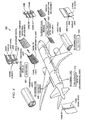
- FIG 4 is an illustration depicting major sub-assemblies of the aircraft of Figure 3 in which advantageous embodiments of the disclosure may be implemented.
- aircraft 300 includes various major sub-assembly components which may be assembled to form the fuselage of the aircraft. These components include single panels 402 which may be assembled to form super panel sub-assemblies 404.
- the super panel sub-assemblies 404 may, in turn, be assembled to form half shell sub-assemblies 406; and the half shell sub-assemblies 406 may be assembled to form barrel sub-assemblies 408.
- the barrel sub-assemblies 408 may finally be assembled to form fuselage assembly 410.
- Sub-assemblies 404, 406, 408, and fuselage assembly 410 are examples of composite structures which may be assembled according to advantageous embodiments of the disclosure. It should be understood, however, that these are intended to be exemplary only as advantageous embodiments are not limited to assembling any particular type of composite structure for any particular type of application.
- Advantageous embodiments provide a method and fastener apparatus for mechanically-joining components to assemble a composite structure for aircraft and other applications that meets electrical conductivity requirements and that provides appropriate strength while meeting material compatibility characteristics.
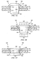
- FIG. 5A is an illustration of a fastener apparatus for mechanically-joining components to assemble a composite structure according to an advantageous embodiment of the disclosure.
- the fastener apparatus is generally designated by reference number 500, and may include a one-piece fastener 502, usually referred to herein as rivet 502, surrounded by a cylindrical-shaped sleeve 504.
- fastener apparatus 500 is shown as extending through aligned holes 510 and 512 in adjacent composite components 514 and 516, respectively, which are to be joined by fastener apparatus 500.
- Composite components 514 and 516 may, for example, be implemented as single panels 402 or other components of any of sub-assemblies 404, 406 or 408 or fuselage assembly 410 illustrated in Figure 4 . It should be understood, however, that this is intended to be exemplary only, as fastener apparatus 500 may be used to join any number of composite components in any application. Also, although Figure 5A illustrates three components, including two composite components, to be joined to form a composite structure, generally designated by reference number 540, fastener apparatus 500 may be used to fasten any number of composite components or may be used to fasten one or more composite components to one or more components that are not formed of composite material. Yet further, although in the advantageous embodiment illustrated in Figure 5A , composite components 514 and 516 comprise flat composite panels, this is also intended to be exemplary only, as composite components 514 and 516 can also be contoured or be of other shapes.
- composite structure 540 may also include an electrically-conductive metallic component 518 such as an electrically-conductive metallic strip between composite components 514 and 516 to facilitate dissipating electrical energy, for example, as a result of a lightning strike.
- an electrically-conductive metallic component 518 such as an electrically-conductive metallic strip between composite components 514 and 516 to facilitate dissipating electrical energy, for example, as a result of a lightning strike.
- fastener apparatus 500 may also extend through hole 528 in metallic strip 518 aligned with holes 510 and 512 in composite components 514 and 516, respectively.
- Electrically-conductive metallic component 518 may also be in the form of, for example and without limitation, a mesh, foil, or screen; and may be a separate layer as shown in Figure 5A , or it may be a layer or ply embedded in one or both of composite components 514 and 516.
- Rivet 502 may be a solid rivet formed of composite material
- sleeve 504 may be a cylindrical-shaped sleeve of an electrically-conductive metallic material, and having an outwardly extending annular collar 522 at one end thereof.
- Both the rivet and the sleeve may be pre-coated in a conventional manner, for example and without limitation, with Hi-Kote 1 TM coating, although as will be explained hereinafter, the outer surface of the sleeve will normally not be pre-coated so as to not interfere with the electrical conductivity characteristics of the sleeve.
- Hi-Kote 1 TM coating and other similar coatings are described in commonly assigned U.S. Patent Numbers 5,614,037 , 5,858,133 , 5,922,472 , and 5,944,918 , the contents of which are herein incorporated by reference.
- rivet 502 may be formed of a thermoplastic polymeric resin.
- Thermoplastic polymeric resins are resins which may be melted and subsequently re-melted, and are often preferred for durable goods manufacturing over thermoset polymeric resins, such as epoxy, which are hardened via chemical reactions.
- Thermoplastic polymers generally have shorter processing times than thermoset polymers and can be subsequently re-heated and re-formed repeatedly if required.
- Thermoset polymeric resins solidify when cured by mixing and/or heating and, once cured, cannot be re-melted or re-molded without significantly changing or altering the material properties of the resin.
- rivet 502 may comprise a thermoplastic fluoropolymer resin such as polyetheretherketone fluoropolymer.
- Polyetheretherketone fluoropolymer is marketed by and available from Victrex Plc. under the trademark PEEK TM .
- Polyetheretherketone polymer is relatively easy to process and combines a number of characteristics that may make it particularly suitable for use in forming rivet 502 of fastener apparatus 500.
- desirable characteristics of polyetheretherketone polymer include the following:
- Polyetheretherketone polymer may safely be used in operating environments having continuous elevated temperatures of up to about +500°F.
- the material has excellent resistance to a wide range of chemical environments, even at elevated temperatures.
- Fluoropolymers may have low tensile strength and surface softness. These properties may be adjusted, however, by adding suitable fillers and/or additives to the polymer, for example, via melt compounding.
- suitable fillers and/or additives for example, via melt compounding.
- short fibers of glass, carbon or titinate in a range of about 20-60 percent by volume, and, more preferably, in a range of about 20-30 percent by volume can be added to the polymer to enhance the strength of rivet 502 without sacrificing any of the desirable thermal, chemical, and electrical properties of the polymer.
- the volume of fiber may also include, in addition to random inclusion of long and short fibers, a woven cylindrical sleeve or stocking of long fibers placed at the outer boundary or perimeter of the rivet to enhance strength.
- the reinforcing fiber assists in reducing inconsistencies while improving dimensional stability, tensile strength, cut-through resistance and the like.
- Insulistencies refers to the difference between one or more measured characteristics of a composite structure under test (and potentially effected by exposure to factor(s) including, but not limited to, thermal load(s), structural load(s), lightning, or electrical arcing) with expected values for the same characteristics of an analogous composite structure unaffected by exposure to those factors.
- rivet 502 may also be formed of polyimide (trade name "Kapton”), polyetherimide (trade name “Ultem”), or polyarylimide (trade name “Torlon”) aromatic fluoropolymer resins.
- Sleeve 504 may be formed of an electrically-conductive metal such as titanium, stainless-steel, Monel TM materials, or another suitable metal that resists corrosion when in contact with the composite components being joined.
- Monel TM may be a suitable metal for use with graphite/epoxy composite components, while a number of metals may be safely used with Kevlar/epoxy composite materials.
- Titanium sleeves may be used with composite components formed of graphite/epoxy without requiring corrosion protection; however, pre-coating is generally recommended and preferred.
- rivet 502 and sleeve 504 may vary depending on the requirements of particular applications. In general, however, rivet 502 may have a relatively large head configuration in order to distribute loads uniformly over a larger surface area. In this regard, composite materials have a lower thickness compression strength than metallic materials, and providing the rivet with a relatively large head provides a greater bearing area or footprint, which may mitigate excessive loads on the composite components being joined. This may reduce crushing of the composite material during installation and assembly of the composite components. Typical rivet heads provide 100-degree and 130-degree countersink configurations. Rivet 502 may have a 130-degree head configuration, as best shown in Figure 5C , to better distribute loads.
- Shank 542 of rivet 502 may protrude or extend beyond the thickness of the stacked components being joined and may facilitate upsetting or forming during installation and to avoid crushing the surrounding composite matrix.
- the length of the protruding portion of shank 542 of rivet 502 may be equal to about 1.1-1.5 times the diameter of the rivet.
- the diameter of rivet 502 may be from about 3/16 inch to about 5/16 inch, although it should be understood that it is not intended to limit advantageous embodiments to rivets having any particular dimensions.
- Sleeve 504 may have an outside diameter substantially equal to the diameter of aligned holes 510 and 512 in composite components 514 and 516 and aligned hole 528 in metallic strip component 518 being joined such that the sleeve will be in direct contact with all of components 514, 516 and 518 to provide a path for the flow of electric current between the components as will be described hereinafter.
- the length of sleeve 504 may be the same as or less than the combined length of aligned holes 510, 512 and 528 in components 514, 516 and 518, respectively, but sleeve 504 should be of sufficient length to ensure being in direct contact with all of components 514, 516 and 518.
- the flared end or annular collar 522 of sleeve 504 may have a diameter substantially equal to the diameter of head 520 of rivet 502 so that the head of the rivet will not come into contact with the composite component 516.
- Collar 522 also serves to properly position sleeve 504 in aligned holes 510, 512 and 528 by virtue of collar 522 coming into contact with the top surface of component 516 during installation of sleeve 504 in the aligned holes to limit the extent to which the sleeve 504 may be inserted into the holes.
- Sleeve 504 may be relatively thin in order to minimize the overall weight of fastener apparatus 500. According to an advantageous embodiment, sleeve 504 may have a thickness of from about 0.008 inch to about 0.016 inch. It should be understood, however, that this is intended to be exemplary only as the thickness of the sleeve may be varied without departing from advantageous embodiments.
- the clearance may be from about +0.002 inch to about +0.004 inch.
- shank 542 expands to provide a net or interference-fit installation.
- Rivet 502 may be installed by applying localized heating to the rivet to soften it, and then squeezing the rivet to deform it. Hydraulically-driven fastening may not be recommended.
- Figure 5B is an illustration of the fastener apparatus of Figure 5A during installation according to an advantageous embodiment of the disclosure. As shown in Figure 5B , rivet 502 may be squeezed by applying oppositely-directed forces to the head and tail ends of the rivet as represented by arrows 530 and 532, respectively. In the advantageous embodiments described herein, when fastener apparatus 500 is in place with mating components 514, 516 and 518, heat and a deforming force may then be applied to the composite rivet by a fastener installation tool.
- the applied heat may be at a temperature of from about 600-900 degrees F and may be applied for about 1-5 minutes depending on the type and size of the rivet.
- the heat and deforming force applied by the fastener installation tool causes the protruding rivet shank to deform and expand, creating a rivet upset.
- rivet 502 is allowed to cool. This cooling results in composite rivet 502 re-consolidating or re-solidifying in a manner that the rivet upset retains the assembled composite components. In this manner, composite components 514 and 516 and electrically-conductive metallic component 518 are mechanically-fastened or joined together.
- the fastener installation tool may take various forms.
- the fastener installation tool may be a hand tool in which fastener apparatus 500 is put into position and placed through aligned components 514, 516 and 518 by hand.
- the fastener installation tool provides heat and force to cause re-shaping or re-forming of the composite material within the protruding portion of rivet shank 542.
- the fastener installation tool may be an automated or robotic-type system in which the fastener installation tool contains or retrieves a supply of fasteners to join aligned components 514, 516 and 518 to each other.
- FIG. 5C is an illustration of the fastener apparatus of Figures 5A and 5B after installation according to an advantageous embodiment of the disclosure.
- the shank protrusion of the rivet has now also been deformed outwardly as shown at 544 so as to securely join composite components 514 and 516 and electrically-conductive metallic component 518.
- the configuration or shape of rivet upset 544 in Figure 3 is intended to be exemplary only, as rivet upset 544 may also be of other configurations or shapes.
- Holes 510 and 512 in composite components 514 and 516 may be formed during manufacture of the components or they may be drilled after alignment and prior to assembly. When composite components, such as carbon-fiber composite components are drilled, fibers within the components may be exposed. These fibers can absorb water, which may be undesirable. Sealants may be used to prevent moisture absorption, but this solution may both complicate the process and add significant cost. It may also defeat any effort made to maintain electrical continuity between the composite components and the fastener since typical corrosion-inhibiting polysulfide sealants are dielectric in nature and impede conductivity efforts.
- Fastener apparatus may provide a sufficiently tight fit so as to reduce water absorption, as well as maintain fuel-tightness (for composite structures that store fuel) without the need for a sealant.
- Fastener apparatus may provide a significant savings in weight as compared to similar metallic fasteners.
- a typical aircraft for example, may require as many as 200,000 rivets resulting in a weight savings of about 600 pounds when a fastener apparatus according to advantageous embodiments is used to join components as opposed to using a one-piece, metallic rivet-type fastener.
- the resulting reduced weight may translate into a significant savings in fuel costs for operating the aircraft.
- Fastener apparatus also provide an effective path for electrical current to flow between joined composite components. This is because following installation of the fastener apparatus, sleeve 504 may be in direct contact with the electrically-conductive fibers within the joined composite components as well as with the electrically-conductive metallic component incorporated in or sandwiched between the composite components. As a result, sleeve 504 provides a more electrically-conductive path for allowing electric current to flow from one composite component to the other.
- sleeve 504 is normally not pre-coated as such pre-coating may interfere with the ability of the sleeve to conduct electric current between the composite components.
- a fastener apparatus may provide an improved quality of installation as compared to metallic fasteners. This is, in part, due to the fact that any inconsistencies in the holes through which the fastener apparatus extends may be more readily accommodated by the cylindrical sleeve. There may also be a reduction in potential undesirable mechanical effects to the composite components being joined during fastener installation and component assembly including, but not limited to undesirable mechanical effects resulting from expansion or compression of the fastener either during installation or during actual operation. Reworking/replacement of the sleeve or rivet, if necessary, may also be improved thereby mitigating against potential inconsistencies to the surrounding composite structure.
- FIG. 6 is a flowchart that illustrates a method for mechanically-joining components in order to assemble a composite structure according to an advantageous embodiment of the disclosure.
- the method is generally designated by reference number 600, and begins by providing first and second components and an electrically-conductive metallic component that are to be joined to provide the composite structure (Step 602). At least one and preferably both of the first and second components may be a composite component.
- a hole may be provided in each of the first and second components and in the electrically-conductive metallic component (Step 604).
- the holes may, for example, be provided by drilling the holes. Alternatively, the holes may be provided in the components prior to the time of assembly when the components are manufactured, or may be provided in another manner.
- the first and second components and the electrically-conductive metallic component may be aligned with one another with the electrically-conductive metallic component sandwiched between the first and second composite components or incorporated in one or both of the first and second components as an embedded layer or ply thereof (Step 606).
- the components may be aligned by first forming the holes in the components and then aligning the holes or the components may first be aligned and the holes then simultaneously drilled through the aligned components. In either event, the holes should be drilled to minimize splintering and fraying with any loose fibers of the composite components being removed.
- a fastener apparatus comprising a composite rivet surrounded by a metallic sleeve is then placed in the aligned holes such that the sleeve is in direct contact with both the first and the second components and with the electrically-conductive metallic component (Step 608).
- the sleeve may include an annular collar extending from an end thereof to assist in placing the sleeve.
- the metallic sleeve and the composite rivet may be pre-assembled prior to their being placed in the aligned holes, or they may be placed in the aligned holes one at a time, in which case, the sleeve may be first placed in the aligned holes, and then the composite rivet may be placed in the sleeve.
- a head of the rivet seats flush into the collar portion of the sleeve, and a cylindrical shank of the rivet extends or protrudes from the opposite side of the aligned holes beyond the structure to be assembled.
- Both the inside diameter of the metallic sleeve and the surfaces of the composite rivet may be pre-coated, if desired.
- Installation tooling may then be provided (Step 610), and both heat and a deforming force may then be applied to the composite rivet to soften and deform the rivet to join the first and second components and the electrically-conductive metallic component to form an assembled composite structure (Step 612).
- the deforming force may be a squeezing force that deforms the protruding shank of the rivet to form a securely joined, assembled composite structure.
- the applied heat may be at a temperature of from about 600-900 degrees F and may be applied for about 1-5 minutes depending on the type, size, and resin material of the rivet.
- the rivet is allowed to cool to room temperature (Step 614), and the installation tooling is removed (Step 616).
Landscapes
- Engineering & Computer Science (AREA)
- Mechanical Engineering (AREA)
- General Engineering & Computer Science (AREA)
- Chemical & Material Sciences (AREA)
- Composite Materials (AREA)
- Connection Of Plates (AREA)
- Insertion Pins And Rivets (AREA)
Abstract
Description
- The disclosure relates generally to a method and apparatus for assembling a structure by joining components that include components of non-metallic material. More particularly, the disclosure relates to a method and fastener apparatus for mechanically-joining components to assemble composite structures for aircraft and other applications.
- The use of structures comprised of composite materials has grown in popularity in recent years, particularly in such applications as aircraft, where benefits include exceptional durability and maintainability and a significant savings in weight.
- Although composite structures are used in both civil and military aircraft, until quite recently, their use has been generally limited to secondary aircraft components and parts. There has been some reluctance to use composite materials for larger aircraft parts and primary structural airframe components.
- Composite structures used in aircraft and other applications are often assembled from a plurality of individual composite components. One particular area of concern in connection with the use of assembled composite structures is the need to mechanically-join the composite components in order to assemble the structure. Despite the development of large co-cured composite structures and the continued refinement in bonding techniques, there remains a need to mechanically-join composite components used in an aircraft, particularly those composite components that may have to be removed for rework or replacement at some stage during the life of an aircraft.
- Mechanical fasteners have been used for many years to assemble metallic structures used in aircraft applications, and procedures for assembling metallic structures are relatively straightforward. Using mechanical fasteners to assemble structures formed of advanced composite materials, however, requires a significantly different technological approach than when assembling metallic structures. The full advantages of composite materials cannot be achieved unless there is some reliable mechanism for mechanically-joining components formed of composite material.
- Assembling composite structures by mechanically-joining components formed of composite materials such as carbon, epoxy, graphite, carbon/aramid, aramid, and glass-reinforced composite materials, using fasteners formed entirely of metallic components, is well-known in the aircraft industry. Metallic fasteners that are often used to assemble composite structures in aircraft include solid rivets, threaded pins, two-piece bolts, and blind fasteners made of Monel™ metal, titanium, stainless steel, and aluminum-alloy materials. Metallic fasteners, however, are not fully satisfactory for joining components formed of composite materials for several reasons.
- Initially, although the solid metallic rivet is the simplest fastener type, when conventional solid metallic rivets, such as solid Monel™ rivets, are used to join components formed of composite materials, the rivets can be less than desirable because the rivets tend to radially expand during installation and produce an edgewise pressure on the composite components. Metallic fasteners, such as aluminum-alloy and stainless-steel fasteners, also expand and contract when exposed to temperature extremes, as may be encountered when used in aircraft applications, which is also less than desirable. Particularly when the components are formed of a carbon-fiber composite material, as is commonly used in aircraft applications, the contraction and expansion of metallic fasteners may cause changes in clamping or preloads associated with the fasteners.
- Metallic fasteners used to join composite components may also be subjected to the combined effects of composite relaxation, progressive hole wear caused by cocking or prying forces, thermal variations, and the like.
- A particularly significant problem with the use of metallic fasteners for joining composite components is that of galvanic corrosion. Galvanic corrosion may occur when metallic materials, especially aluminum-alloy material, are in contact with composite materials, particularly carbon-fiber composite materials. Galvanic corrosion may be due to chemical reaction of the aluminum with the carbon fibers of the composite components being joined. Although it may be known to apply a sacrificial or protective coating to conventional metallic fasteners to help guard against galvanic corrosion, the coating increases the cost of the fasteners. Fasteners formed of titanium, stainless-steel, or Monel™ materials are better able to resist the problem of galvanic corrosion and may be used instead of aluminum-alloy fasteners to join carbon-fiber composite components. Such fasteners, however, are more expensive than aluminum-alloy fasteners.
- In order to prevent contact with the carbon fibers in carbon-fiber composite materials, fastener manufacturers have also tried using various material combinations, including steel and aluminum-alloy fasteners with glass fiber or adhesive-scrim insulation. These material combinations are also not fully satisfactory.
- Manufacturers have also experimented with mechanical fasteners formed of composite materials rather than metal. For example, glass or carbon epoxy fasteners are known. Fasteners formed of composite materials, however, are not fully satisfactory in applications such as aircraft applications because they may not provide or achieve appropriate strength and material compatibility characteristics, or meet electrical conductivity requirements.
- In particular, aircraft structures must provide a mechanism for dissipating electrical energy, for example, electrical energy generated as a result of the aircraft being struck by lightning. Composite structures used in aircraft, accordingly, typically include an electrically-conductive metallic component that may be sandwiched between assembled composite components or provided as a layer of the composite components to facilitate and satisfy electrical discharge requirements by directing electrical current toward external boundaries of the aircraft, such as wing tips.
- If composite fasteners are used to join composite components, however, electric current may be restricted from flowing freely between the joined components; and, as a result, may not provide a suitable path for dissipating electrical current if, for example, the aircraft is struck by lightning. Also, without a suitable path to dissipate electric current, electric potential may build up, and when the electrical potential becomes great enough, a spark or electrical arcing may occur, which may be undesirable for the structure of the aircraft or may cause "noise" in the communications radio or other electrical systems of the aircraft.
- There is, accordingly, a need for a mechanism for mechanically-joining components to assemble a composite structure, such as a composite structure of an aircraft, that meets electrical conductivity requirements while providing appropriate strength and material compatibility characteristics.
- An embodiment of the disclosure provides a method for mechanically-joining components to assemble a composite structure. A first component and a second component may be provided. At least one of the first and second components may comprise a composite component. A hole may be formed in each of the first and second components. A metallic sleeve may be placed in the holes in the first and second components such that the metallic sleeve is in contact with the first and second components, and a composite rivet may be placed in the metallic sleeve. Heat and a deforming force may be applied to the composite rivet to join the first and second components to form an assembled composite structure.
- A further embodiment of the disclosure provides a fastener apparatus for mechanically-joining components to assemble a composite structure. The fastener apparatus may include a composite rivet and a metallic sleeve surrounding the composite rivet.
- A further embodiment of the disclosure provides a method for mechanically-joining components to assemble a composite structure of an aircraft. A first component and a second component may be provided. At least one of the first and second components may comprise a composite component. An electrically-conductive metallic component may be provided. A metallic sleeve may be placed in holes in the first and second components and the electrically-conductive metallic component such that the metallic sleeve is in contact with the first and second components and the electrically-conductive metallic component, and a composite rivet may be placed in the metallic sleeve such that the composite rivet extends through the metallic sleeve. Heat and a deforming force may be applied to the composite rivet to join the first and second components and the electrically-conductive metallic component, such that the joined first and second components and the electrically-conductive metallic component form an assembled composite structure.
- Preferably, the metallic sleeve comprises one of a titanium, stainless-steel, and Monel™ metallic sleeve.
- Preferably, the first and second components comprise carbon-fiber composite components.
- Preferably the composite structure comprises a composite structure of an aircraft.
- According to another aspect of the invention there is provided a method for mechanically-joining composite components to assemble a composite structure of an aircraft, comprising: providing a first component and a second component, at least one of the first and second components comprising a composite component; providing an electrically-conductive metallic component; placing a metallic sleeve in holes in the first and second components and the electrically-conductive metallic component such that the metallic sleeve is in contact with the first and second components and the electrically-conductive metallic component; placing a composite rivet in the metallic sleeve such that the composite rivet extends through the metallic sleeve; and applying heat and a deforming force to the composite rivet to join the first and second components and the electrically-conductive metallic component, such that the joined first and second components and the electrically-conductive metallic component form an assembled composite structure.
- Preferably, the composite rivet comprises a fluoropolymer composite rivet, and the metallic sleeve comprises one of a titanium, stainless steel, and Monel™ metallic sleeve.
- The features, functions, and advantages can be achieved independently in various embodiments or may be combined in yet other embodiments.
- The novel features believed characteristic of the embodiments are set forth in the appended claims. The embodiments themselves, however, as well as a preferred mode of use, further objectives and advantages thereof, will best be understood by reference to the following detailed description of advantageous embodiments when read in conjunction with the accompanying drawings.
-
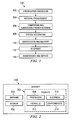
Figure 1 is a flow diagram of aircraft production and service methodology; -
Figure 2 is a block diagram of an aircraft; -
Figure 3 is an illustration of an aircraft in which advantageous embodiments of the disclosure may be implemented; -
Figure 4 is an illustration depicting major sub-assemblies of the aircraft ofFigure 3 in which advantageous embodiments of the disclosure may be implemented; -
Figure 5A is an illustration of a fastener apparatus for mechanically-joining components to assemble a composite structure according to an advantageous embodiment of the disclosure; -
Figure 5B is an illustration of the fastener apparatus ofFigure 5A during installation according to an advantageous embodiment of the disclosure; -
Figure 5C is an illustration of the fastener apparatus ofFigures 5A and 5B after installation according to an advantageous embodiment of the disclosure; and -
Figure 6 is a flowchart that illustrates a method for mechanically-joining components in order to assemble a composite structure according to an advantageous embodiment of the disclosure. - Referring more particularly to the drawings, embodiments of the disclosure may be described in the context of an aircraft manufacturing and
service method 100 as shown inFigure 1 and anaircraft 200 as shown inFigure 2 . During pre-production,exemplary method 100 may include specification anddesign 102 of theaircraft 200 inFigure 2 andmaterial procurement 104. During production, component andsub-assembly manufacturing 106 andsystem integration 108 of theaircraft 102 takes place. Thereafter, theaircraft 200 inFigure 2 may go through certification anddelivery 110 in order to be placed inservice 112. While in service by a customer, theaircraft 200 inFigure 2 is scheduled for routine maintenance and service 114 (which may also include modification, reconfiguration, refurbishment, and so on). - Each of the processes of
method 100 may be performed or carried out by a system integrator, a third party, and/or an operator (e.g., a customer). For the purposes of this description, a system integrator may include without limitation any number of aircraft manufacturers and major-system subcontractors; a third party may include without limitation any number of venders, subcontractors, and suppliers; and an operator may be an airline, leasing company, military entity, service organization, and so on. - As shown in
Figure 2 , theaircraft 200 produced byexemplary method 100 may include anairframe 202 with a plurality ofsystems 204 and an interior 206. Examples of high-level systems 204 include one or more of apropulsion system 208, anelectrical system 210, ahydraulic system 212, and anenvironmental system 214. Any number of other systems may be included. Although an aerospace example is shown, the principles of the invention may be applied to other industries, such as the automotive industry. - Apparatus and methods embodied herein may be employed during any one or more of the stages of the production and
service method 100. For example, components or sub-assemblies corresponding toproduction process 106 may be fabricated or manufactured in a manner similar to components or sub-assemblies produced while theaircraft 200 is in service. Also, one or more apparatus embodiments, method embodiments, or a combination thereof may be utilized during the production stages 106 and 108, for example, by substantially expediting assembly of or reducing the cost of anaircraft 200. Similarly, one or more of apparatus embodiments, method embodiments, or a combination thereof may be utilized while theaircraft 200 is in service, for example and without limitation, maintenance andservice 114. - With reference now to
Figure 3 , an illustration of an aircraft is depicted in which advantageous embodiments of the disclosure may be implemented. More particularly,aircraft 300, which may be implemented asaircraft 200 inFigure 2 , is an example of an application which may utilize composite structures assembled by a method and apparatus for mechanically-joining composite components in accordance with advantageous embodiments of the disclosure. - In this illustrative example,
aircraft 300 haswings body 306.Aircraft 300 includes wing mountedengines aircraft 300 also includes horizontal andvertical stabilizers - The use of structures formed of composite materials on aircraft has grown in popularity, in part, because such structures provide benefits of exceptional durability and maintainability and a significant savings in weight.
Aircraft 300 may, for example, include compositestructures forming body 306,wings vertical stabilizers -
Figure 4 is an illustration depicting major sub-assemblies of the aircraft ofFigure 3 in which advantageous embodiments of the disclosure may be implemented. As shown inFigure 4 ,aircraft 300 includes various major sub-assembly components which may be assembled to form the fuselage of the aircraft. These components includesingle panels 402 which may be assembled to formsuper panel sub-assemblies 404. Thesuper panel sub-assemblies 404 may, in turn, be assembled to formhalf shell sub-assemblies 406; and thehalf shell sub-assemblies 406 may be assembled to formbarrel sub-assemblies 408. Thebarrel sub-assemblies 408 may finally be assembled to form fuselage assembly 410. -
Sub-assemblies - Despite the development of large co-cured composite structures and the continued refinement in bonding techniques, there remains a need to mechanically-join composite components used in an aircraft, particularly those composite components that might have to be removed for rework or replacement at some stage during the life of an aircraft.
- Although mechanical fasteners have been used for many years to assemble metallic structures used in aircraft applications, and procedures for assembling metallic structures are relatively straightforward; using mechanical fasteners to assemble structures formed of advanced composite materials may benefit from a significantly different technological approach than when assembling metallic structures.
- Advantageous embodiments provide a method and fastener apparatus for mechanically-joining components to assemble a composite structure for aircraft and other applications that meets electrical conductivity requirements and that provides appropriate strength while meeting material compatibility characteristics.
-
Figure 5A is an illustration of a fastener apparatus for mechanically-joining components to assemble a composite structure according to an advantageous embodiment of the disclosure. The fastener apparatus is generally designated byreference number 500, and may include a one-piece fastener 502, usually referred to herein asrivet 502, surrounded by a cylindrical-shapedsleeve 504. In the advantageous embodiment illustrated inFigure 5A ,fastener apparatus 500 is shown as extending through alignedholes composite components fastener apparatus 500.Composite components single panels 402 or other components of any ofsub-assemblies Figure 4 . It should be understood, however, that this is intended to be exemplary only, asfastener apparatus 500 may be used to join any number of composite components in any application. Also, althoughFigure 5A illustrates three components, including two composite components, to be joined to form a composite structure, generally designated byreference number 540,fastener apparatus 500 may be used to fasten any number of composite components or may be used to fasten one or more composite components to one or more components that are not formed of composite material. Yet further, although in the advantageous embodiment illustrated inFigure 5A ,composite components composite components - As shown in
Figure 5A ,composite structure 540 may also include an electrically-conductivemetallic component 518 such as an electrically-conductive metallic strip betweencomposite components metallic strip 518 is included incomposite structure 540,fastener apparatus 500 may also extend throughhole 528 inmetallic strip 518 aligned withholes composite components metallic component 518 may also be in the form of, for example and without limitation, a mesh, foil, or screen; and may be a separate layer as shown inFigure 5A , or it may be a layer or ply embedded in one or both ofcomposite components -
Rivet 502 may be a solid rivet formed of composite material, andsleeve 504 may be a cylindrical-shaped sleeve of an electrically-conductive metallic material, and having an outwardly extendingannular collar 522 at one end thereof. Both the rivet and the sleeve may be pre-coated in a conventional manner, for example and without limitation, with Hi-Kote 1™ coating, although as will be explained hereinafter, the outer surface of the sleeve will normally not be pre-coated so as to not interfere with the electrical conductivity characteristics of the sleeve. The Hi-Kote 1™ coating and other similar coatings are described in commonly assignedU.S. Patent Numbers 5,614,037 ,5,858,133 ,5,922,472 , and5,944,918 , the contents of which are herein incorporated by reference. - According to an advantageous embodiment, rivet 502 may be formed of a thermoplastic polymeric resin. Thermoplastic polymeric resins are resins which may be melted and subsequently re-melted, and are often preferred for durable goods manufacturing over thermoset polymeric resins, such as epoxy, which are hardened via chemical reactions. Thermoplastic polymers generally have shorter processing times than thermoset polymers and can be subsequently re-heated and re-formed repeatedly if required. Thermoset polymeric resins, on the other hand, solidify when cured by mixing and/or heating and, once cured, cannot be re-melted or re-molded without significantly changing or altering the material properties of the resin.
- According to an advantageous embodiment of the disclosure, rivet 502 may comprise a thermoplastic fluoropolymer resin such as polyetheretherketone fluoropolymer. Polyetheretherketone fluoropolymer is marketed by and available from Victrex Plc. under the trademark PEEK™.
- Polyetheretherketone polymer is relatively easy to process and combines a number of characteristics that may make it particularly suitable for use in forming
rivet 502 offastener apparatus 500. Among the desirable characteristics of polyetheretherketone polymer include the following: - ➢ chemical resistance;
- ➢ abrasion resistance;
- ➢ high-temperature resistance;
- ➢ hydrolysis resistance;
- ➢ flame resistance with low smoke and toxic gases;
- ➢ excellent electrical properties; and
- ➢ excellent resistance to gamma rays.
- Polyetheretherketone polymer may safely be used in operating environments having continuous elevated temperatures of up to about +500°F. The material has excellent resistance to a wide range of chemical environments, even at elevated temperatures. Fluoropolymers may have low tensile strength and surface softness. These properties may be adjusted, however, by adding suitable fillers and/or additives to the polymer, for example, via melt compounding. For example, short fibers of glass, carbon or titinate in a range of about 20-60 percent by volume, and, more preferably, in a range of about 20-30 percent by volume, can be added to the polymer to enhance the strength of
rivet 502 without sacrificing any of the desirable thermal, chemical, and electrical properties of the polymer. In addition, the volume of fiber may also include, in addition to random inclusion of long and short fibers, a woven cylindrical sleeve or stocking of long fibers placed at the outer boundary or perimeter of the rivet to enhance strength. In general, the reinforcing fiber assists in reducing inconsistencies while improving dimensional stability, tensile strength, cut-through resistance and the like. "Inconsistencies," as the term is used in the appropriate context throughout this disclosure, refers to the difference between one or more measured characteristics of a composite structure under test (and potentially effected by exposure to factor(s) including, but not limited to, thermal load(s), structural load(s), lightning, or electrical arcing) with expected values for the same characteristics of an analogous composite structure unaffected by exposure to those factors. - It should be understood that although advantageous embodiments include rivets formed of polyetheretherketone polymer, other fluoropolymers and other polymers may also be used for
rivet 502. For example, rivet 502 may also be formed of polyimide (trade name "Kapton"), polyetherimide (trade name "Ultem"), or polyarylimide (trade name "Torlon") aromatic fluoropolymer resins. -
Sleeve 504 may be formed of an electrically-conductive metal such as titanium, stainless-steel, Monel™ materials, or another suitable metal that resists corrosion when in contact with the composite components being joined. Monel™ may be a suitable metal for use with graphite/epoxy composite components, while a number of metals may be safely used with Kevlar/epoxy composite materials. Titanium sleeves may be used with composite components formed of graphite/epoxy without requiring corrosion protection; however, pre-coating is generally recommended and preferred. - The configuration and the dimensions of
rivet 502 andsleeve 504 may vary depending on the requirements of particular applications. In general, however, rivet 502 may have a relatively large head configuration in order to distribute loads uniformly over a larger surface area. In this regard, composite materials have a lower thickness compression strength than metallic materials, and providing the rivet with a relatively large head provides a greater bearing area or footprint, which may mitigate excessive loads on the composite components being joined. This may reduce crushing of the composite material during installation and assembly of the composite components. Typical rivet heads provide 100-degree and 130-degree countersink configurations.Rivet 502 may have a 130-degree head configuration, as best shown inFigure 5C , to better distribute loads. -
Shank 542 ofrivet 502 may protrude or extend beyond the thickness of the stacked components being joined and may facilitate upsetting or forming during installation and to avoid crushing the surrounding composite matrix. The length of the protruding portion ofshank 542 ofrivet 502 may be equal to about 1.1-1.5 times the diameter of the rivet. The diameter ofrivet 502 may be from about 3/16 inch to about 5/16 inch, although it should be understood that it is not intended to limit advantageous embodiments to rivets having any particular dimensions. -
Sleeve 504 may have an outside diameter substantially equal to the diameter of alignedholes composite components hole 528 inmetallic strip component 518 being joined such that the sleeve will be in direct contact with all ofcomponents sleeve 504 may be the same as or less than the combined length of alignedholes components sleeve 504 should be of sufficient length to ensure being in direct contact with all ofcomponents annular collar 522 ofsleeve 504 may have a diameter substantially equal to the diameter ofhead 520 ofrivet 502 so that the head of the rivet will not come into contact with thecomposite component 516.Collar 522 also serves to properly positionsleeve 504 in alignedholes collar 522 coming into contact with the top surface ofcomponent 516 during installation ofsleeve 504 in the aligned holes to limit the extent to which thesleeve 504 may be inserted into the holes. -
Sleeve 504 may be relatively thin in order to minimize the overall weight offastener apparatus 500. According to an advantageous embodiment,sleeve 504 may have a thickness of from about 0.008 inch to about 0.016 inch. It should be understood, however, that this is intended to be exemplary only as the thickness of the sleeve may be varied without departing from advantageous embodiments. - There may be an initial clearance between
sleeve 504 and rivet 502 so as to avoid an interference fit. Typically, the clearance may be from about +0.002 inch to about +0.004 inch. During installation ofrivet 502,shank 542 expands to provide a net or interference-fit installation. -
Rivet 502 may be installed by applying localized heating to the rivet to soften it, and then squeezing the rivet to deform it. Hydraulically-driven fastening may not be recommended.Figure 5B is an illustration of the fastener apparatus ofFigure 5A during installation according to an advantageous embodiment of the disclosure. As shown inFigure 5B , rivet 502 may be squeezed by applying oppositely-directed forces to the head and tail ends of the rivet as represented byarrows fastener apparatus 500 is in place withmating components composite rivet 502 re-consolidating or re-solidifying in a manner that the rivet upset retains the assembled composite components. In this manner,composite components metallic component 518 are mechanically-fastened or joined together. - The fastener installation tool (not shown) may take various forms. For example, the fastener installation tool may be a hand tool in which
fastener apparatus 500 is put into position and placed through alignedcomponents rivet shank 542. In other examples, the fastener installation tool may be an automated or robotic-type system in which the fastener installation tool contains or retrieves a supply of fasteners to join alignedcomponents - In
Figure 5B , thehead 520 ofrivet 502 has been placed intohole 512 ofcomposite component 516 such thathead 520 no longer protrudes from the hole. During the installation process,cylindrical sleeve 504 and itsannular collar 522 have been deformed to correspond to the hole. -
Figure 5C is an illustration of the fastener apparatus ofFigures 5A and 5B after installation according to an advantageous embodiment of the disclosure. As shown inFigure 5C , the shank protrusion of the rivet has now also been deformed outwardly as shown at 544 so as to securely joincomposite components metallic component 518. In this regard, it should be understood that the configuration or shape of rivet upset 544 inFigure 3 is intended to be exemplary only, as rivet upset 544 may also be of other configurations or shapes. -
Holes composite components - Fastener apparatus according to advantageous embodiments may provide a significant savings in weight as compared to similar metallic fasteners. A typical aircraft, for example, may require as many as 200,000 rivets resulting in a weight savings of about 600 pounds when a fastener apparatus according to advantageous embodiments is used to join components as opposed to using a one-piece, metallic rivet-type fastener. The resulting reduced weight may translate into a significant savings in fuel costs for operating the aircraft.
- Fastener apparatus according to advantageous embodiments also provide an effective path for electrical current to flow between joined composite components. This is because following installation of the fastener apparatus,
sleeve 504 may be in direct contact with the electrically-conductive fibers within the joined composite components as well as with the electrically-conductive metallic component incorporated in or sandwiched between the composite components. As a result,sleeve 504 provides a more electrically-conductive path for allowing electric current to flow from one composite component to the other. This may be particularly important in aircraft applications to provide a path for dissipating electrical energy generated as a result of the aircraft being struck by lightning or to prevent a build up of electrical potential which may cause an arc or spark which may have an undesirable effect on structures or, at least, undesirable "noise" in the electrical systems of the aircraft. As indicated previously, the outer surface ofsleeve 504 is normally not pre-coated as such pre-coating may interfere with the ability of the sleeve to conduct electric current between the composite components. - In general, a fastener apparatus according to advantageous embodiments may provide an improved quality of installation as compared to metallic fasteners. This is, in part, due to the fact that any inconsistencies in the holes through which the fastener apparatus extends may be more readily accommodated by the cylindrical sleeve. There may also be a reduction in potential undesirable mechanical effects to the composite components being joined during fastener installation and component assembly including, but not limited to undesirable mechanical effects resulting from expansion or compression of the fastener either during installation or during actual operation. Reworking/replacement of the sleeve or rivet, if necessary, may also be improved thereby mitigating against potential inconsistencies to the surrounding composite structure.
-
Figure 6 is a flowchart that illustrates a method for mechanically-joining components in order to assemble a composite structure according to an advantageous embodiment of the disclosure. The method is generally designated byreference number 600, and begins by providing first and second components and an electrically-conductive metallic component that are to be joined to provide the composite structure (Step 602). At least one and preferably both of the first and second components may be a composite component. A hole may be provided in each of the first and second components and in the electrically-conductive metallic component (Step 604). The holes may, for example, be provided by drilling the holes. Alternatively, the holes may be provided in the components prior to the time of assembly when the components are manufactured, or may be provided in another manner. - The first and second components and the electrically-conductive metallic component may be aligned with one another with the electrically-conductive metallic component sandwiched between the first and second composite components or incorporated in one or both of the first and second components as an embedded layer or ply thereof (Step 606). The components may be aligned by first forming the holes in the components and then aligning the holes or the components may first be aligned and the holes then simultaneously drilled through the aligned components. In either event, the holes should be drilled to minimize splintering and fraying with any loose fibers of the composite components being removed.
- A fastener apparatus comprising a composite rivet surrounded by a metallic sleeve is then placed in the aligned holes such that the sleeve is in direct contact with both the first and the second components and with the electrically-conductive metallic component (Step 608). The sleeve may include an annular collar extending from an end thereof to assist in placing the sleeve.
- The metallic sleeve and the composite rivet may be pre-assembled prior to their being placed in the aligned holes, or they may be placed in the aligned holes one at a time, in which case, the sleeve may be first placed in the aligned holes, and then the composite rivet may be placed in the sleeve.
- When the fastener apparatus is positioned in the aligned holes, a head of the rivet seats flush into the collar portion of the sleeve, and a cylindrical shank of the rivet extends or protrudes from the opposite side of the aligned holes beyond the structure to be assembled. Both the inside diameter of the metallic sleeve and the surfaces of the composite rivet may be pre-coated, if desired.
- Installation tooling may then be provided (Step 610), and both heat and a deforming force may then be applied to the composite rivet to soften and deform the rivet to join the first and second components and the electrically-conductive metallic component to form an assembled composite structure (Step 612). More particularly, the deforming force may be a squeezing force that deforms the protruding shank of the rivet to form a securely joined, assembled composite structure. The applied heat may be at a temperature of from about 600-900 degrees F and may be applied for about 1-5 minutes depending on the type, size, and resin material of the rivet.
- Following joining of the components, the rivet is allowed to cool to room temperature (Step 614), and the installation tooling is removed (Step 616).
- The description of the different advantageous embodiments has been presented for purposes of illustration and description, and is not intended to be exhaustive or limited to the embodiments in the form disclosed. Many modifications and variations will be apparent to those of ordinary skill in the art. Further, different advantageous embodiments may provide different advantages as compared to other advantageous embodiments. The embodiment or embodiments selected are chosen and described in order to best explain the principles of the disclosure, the practical application, and to enable others of ordinary skill in the art to understand the disclosure for various embodiments with various modifications as are suited to the particular use contemplated.
Claims (15)
- A method for mechanically-joining components to assemble a composite structure, comprising:providing a first component and a second component, at least one of the first and second components comprising a composite component;forming a hole in each of the first and second components;placing a metallic sleeve in the holes in the first and second components such that the metallic sleeve is in contact with the first and second components;placing a composite rivet in the metallic sleeve; andapplying heat and a deforming force to the composite rivet to join the first and second components to form an assembled composite structure.
- The method according to claim 1, and further comprising:aligning the holes in the first and second components.
- The method according to claim 1, wherein forming a hole in each of the first and second components comprises:drilling the hole in each of the first and second components.
- The method according to claim 1, wherein the step of placing the metallic sleeve in the holes in the first and second components, and the step of placing the composite rivet in the metallic sleeve comprises:pre-assembling the metallic sleeve and the composite rivet; andplacing the pre-assembled metallic sleeve and composite rivet in the holes in the first and second components.
- The method according to claim 1, and further comprising:providing an electrically-conductive metallic component, wherein placing the metallic sleeve in the holes in the first and second components such that the metallic sleeve is in contact with the first and second components, comprises:placing the metallic sleeve in the holes in the first and second components such that the metallic sleeve is in contact with the first and second components and the electrically-conductive metallic component.
- The method according to claim 5, wherein providing an electrically-conductive metallic component comprises one of providing an electrically-conductive metallic component between the first and second components, and providing an electrically-conductive metallic component as a layer of at least one of the first and second components.
- The method according to claim 1, wherein the composite rivet comprises a fluoropolymer composite rivet.
- The method according to claim 7, wherein the fluoropolymer composite rivet comprises a polyetheretherketone fluoropolymer composite rivet.
- The method according to claim 1, wherein the composite rivet comprises a fiber-reinforced composite rivet.
- A fastener apparatus for mechanically-joining components to assemble a composite structure, comprising:a composite rivet; anda metallic sleeve surrounding the composite rivet.
- The fastener apparatus according to claim 10, wherein the composite rivet comprises a fluoropolymer composite rivet.
- The fastener apparatus according to claim 11, wherein the fluoropolymer composite rivet comprises a polyetheretherketone fluoropolymer composite rivet.
- The fastener apparatus according to claim 10, wherein the composite rivet comprises a fiber-reinforced composite rivet.
- The fastener apparatus according to claim 10, wherein the metallic sleeve comprises one of a titanium, stainless steel, and Monel™ metallic sleeve.
- The fastener apparatus according to claim 10, wherein the composite rivet and the metallic sleeve comprise a pre-assembled fastener apparatus.
Applications Claiming Priority (1)
| Application Number | Priority Date | Filing Date | Title |
|---|---|---|---|
| US11/935,949 US8393068B2 (en) | 2007-11-06 | 2007-11-06 | Method and apparatus for assembling composite structures |
Publications (2)
| Publication Number | Publication Date |
|---|---|
| EP2058111A1 true EP2058111A1 (en) | 2009-05-13 |
| EP2058111B1 EP2058111B1 (en) | 2012-05-16 |
Family
ID=40243724
Family Applications (1)
| Application Number | Title | Priority Date | Filing Date |
|---|---|---|---|
| EP08253594A Active EP2058111B1 (en) | 2007-11-06 | 2008-11-04 | Method and apparatus for assembling composite structures using a composite rivet |
Country Status (5)
| Country | Link |
|---|---|
| US (1) | US8393068B2 (en) |
| EP (1) | EP2058111B1 (en) |
| JP (1) | JP5361337B2 (en) |
| CN (1) | CN101474658B (en) |
| CA (1) | CA2642123C (en) |
Cited By (5)
| Publication number | Priority date | Publication date | Assignee | Title |
|---|---|---|---|---|
| ITTO20100218A1 (en) * | 2010-03-22 | 2011-09-23 | Alenia Aermacchi Spa | PLUG FOR THE POSITIONING OF COMPOSITE PARTS. |
| US8393068B2 (en) * | 2007-11-06 | 2013-03-12 | The Boeing Company | Method and apparatus for assembling composite structures |
| CN103225643A (en) * | 2012-01-30 | 2013-07-31 | 湖北博士隆科技有限公司 | Titanium alloy combined type lock cylinder rivet |
| WO2014064206A1 (en) * | 2012-10-24 | 2014-05-01 | Walter Kiersch | Carbon fiber component having an electrical contact element |
| WO2014182367A1 (en) * | 2013-05-07 | 2014-11-13 | The Boeing Company | Flush Fastener Design and Installation |
Families Citing this family (56)
| Publication number | Priority date | Publication date | Assignee | Title |
|---|---|---|---|---|
| US9586699B1 (en) | 1999-08-16 | 2017-03-07 | Smart Drilling And Completion, Inc. | Methods and apparatus for monitoring and fixing holes in composite aircraft |
| US9625361B1 (en) | 2001-08-19 | 2017-04-18 | Smart Drilling And Completion, Inc. | Methods and apparatus to prevent failures of fiber-reinforced composite materials under compressive stresses caused by fluids and gases invading microfractures in the materials |
| US7966711B2 (en) | 2007-08-14 | 2011-06-28 | The Boeing Company | Method and apparatus for fastening components using a composite two-piece fastening system |
| US7878747B2 (en) * | 2008-07-22 | 2011-02-01 | The Boeing Company | Insulating cover for fasteners used in high temperature environments |
| US8047753B2 (en) | 2008-07-22 | 2011-11-01 | The Boeing Company | Insulating washers |
| US8490955B2 (en) * | 2008-09-19 | 2013-07-23 | The Boeing Company | Electromagnetic clamping device |
| WO2011105540A1 (en) * | 2010-02-26 | 2011-09-01 | 三菱重工業株式会社 | Composite material repair method, and composite material using same |
| DE102010025546A1 (en) * | 2010-06-29 | 2011-12-29 | Suzlon Energy Gmbh | Nacelle paneling |
| JP5602606B2 (en) | 2010-12-13 | 2014-10-08 | 富士重工業株式会社 | Sleeve removal tool and sleeve removal method |
| JP5693195B2 (en) | 2010-12-14 | 2015-04-01 | 三菱重工業株式会社 | Bolt joint structure |
| US20120201999A1 (en) * | 2011-02-08 | 2012-08-09 | Woods Mark A | Methods and apparatus for mechanically joining metal components and composite components |
| DE102011014819A1 (en) * | 2011-03-23 | 2012-09-27 | Airbus Operations Gmbh | Fastening device and method for producing a fastening device |
| JP5675482B2 (en) * | 2011-04-28 | 2015-02-25 | 三菱重工業株式会社 | Fastening method for composite parts |
| FR2976637B1 (en) * | 2011-06-20 | 2015-05-01 | Eris | FASTENING ELEMENT AND METHOD FOR MANUFACTURING THE SAME |
| DE102012001057A1 (en) * | 2012-01-20 | 2013-07-25 | Liebherr-Aerospace Lindenberg Gmbh | Component e.g. fiber reinforced component for landing gear of aircraft, has composite material that produces pressing force acting in axial direction of hole |
| DE102012102290A1 (en) * | 2012-03-19 | 2013-09-19 | Dr. Ing. H.C. F. Porsche Aktiengesellschaft | Fiber composite component of a motor vehicle, Monatageteil for such a fiber composite component and manufacturing process |
| DE102012008798B4 (en) * | 2012-03-31 | 2016-01-14 | Johnson Controls Gmbh | Method of joining and connecting element |
| US8739388B2 (en) | 2012-04-17 | 2014-06-03 | Ford Global Technologies, Llc | Method of fastening parts to a composite part |
| JP5730929B2 (en) * | 2012-06-11 | 2015-06-10 | 株式会社呉英製作所 | Cup type rotating grindstone |
| US9777579B2 (en) | 2012-12-10 | 2017-10-03 | General Electric Company | Attachment of composite article |
| US9797257B2 (en) | 2012-12-10 | 2017-10-24 | General Electric Company | Attachment of composite article |
| US8826510B1 (en) | 2013-02-15 | 2014-09-09 | Ford Global Technologies, Llc | Method of making assemblies including reinforced composite parts with pre-formed rivet receiving buttons and articles made by the method |
| FR3007091B1 (en) * | 2013-06-18 | 2015-07-03 | Herakles | SELF-TEMPERATURE BONDING ASSEMBLY |
| US9653194B2 (en) | 2013-08-12 | 2017-05-16 | Te Connectivity Corporation | Low resistance insert |
| DE102014203761A1 (en) * | 2014-02-28 | 2015-09-03 | Bayerische Motoren Werke Aktiengesellschaft | Method for mounting a component made of a fiber composite material in the power flow of a clamping connection |
| US9937549B2 (en) * | 2014-07-09 | 2018-04-10 | The Boeing Company | Two-stage riveting |
| KR20160033879A (en) * | 2014-09-18 | 2016-03-29 | 주식회사 성우하이텍 | Self piercing projection welding rivet, joint structure and joint method using the same |
| US10160029B2 (en) * | 2014-10-22 | 2018-12-25 | Ford Global Technologies, Llc | System and method for assembling vehicle components with reinforced moldable rivet |
| US9815499B2 (en) | 2014-10-22 | 2017-11-14 | Ford Global Technologies, Llc | Reinforced moldable rivet assembly for a vehicle |
| CN104696365A (en) * | 2015-02-15 | 2015-06-10 | 浙江西田机械有限公司 | Deep groove ball bearing |
| DE102015117784A1 (en) * | 2015-10-19 | 2017-04-20 | Kathrein-Werke Kg | Expanded rivet connection and method for mounting the same |
| US10486378B2 (en) | 2016-08-01 | 2019-11-26 | GM Global Technology Operations LLC | Methods of manufacturing vehicle assemblies |
| US10125809B2 (en) | 2016-08-01 | 2018-11-13 | GM Global Technology Operations LLC | Crankshaft assemblies and methods of manufacturing the same |
| US10267261B2 (en) * | 2016-08-01 | 2019-04-23 | GM Global Technology Operations LLC | Methods of joining components in vehicle assemblies |
| US10408163B2 (en) | 2016-08-01 | 2019-09-10 | GM Global Technology Operations LLC | Polymeric composite engine assembly and methods of heating and cooling said assembly |
| US10640232B2 (en) * | 2016-12-20 | 2020-05-05 | The Boeing Company | Conductive fastening system for composite structures |
| US10280962B2 (en) * | 2017-02-02 | 2019-05-07 | Ford Global Technologies, Llc | Insert for joining components |
| CN107420465A (en) * | 2017-04-24 | 2017-12-01 | 北京优材百慕航空器材有限公司 | Integral dovetail plate train brake pads |
| US10746215B2 (en) * | 2017-05-05 | 2020-08-18 | The Boeing Company | Blade-and-slot joints that unite composite panels via internal blades |
| CN107662350B (en) * | 2017-09-22 | 2019-08-20 | 南京航空航天大学 | A kind of aviation novel hybrid composite riveting method and device |
| JP6778221B2 (en) * | 2018-01-15 | 2020-10-28 | 株式会社Subaru | Fastening structure |
| IT201800003783A1 (en) * | 2018-03-20 | 2019-09-20 | Graf Synergy Srl | PROCEDURE FOR THE REALIZATION OF REINFORCEMENT BARS FOR WINDOWS |
| US11084230B1 (en) | 2018-03-29 | 2021-08-10 | Kineticure, Llc | Bonded nutplate rapid cure system |
| CN108721908B (en) * | 2018-07-23 | 2024-07-19 | 青岛鑫集美工艺品有限公司 | Riveting equipment |
| US11181137B2 (en) * | 2019-05-20 | 2021-11-23 | The Boeing Company | Fastener systems and assemblies for coupling a part to a composite structure, and related methods |
| DE102019207885B3 (en) * | 2019-05-29 | 2020-08-13 | Audi Ag | Process monitoring method, computer program, device for data processing, computer-readable medium and device for process monitoring |
| CN111336035A (en) * | 2020-05-14 | 2020-06-26 | 天津爱思达新材料科技有限公司 | Heat protection device for nozzle of swing rocket engine |
| CN111761019B (en) * | 2020-06-12 | 2022-05-27 | 陕西飞机工业(集团)有限公司 | Large-flat-head rivet and sealing riveting method thereof |
| CN113915206B (en) * | 2021-11-11 | 2023-04-21 | 贵州航天精工制造有限公司 | Assembling and connecting method for composite material structure |
| CN115122656B (en) * | 2022-05-27 | 2023-08-15 | 大连理工大学 | Thermosetting continuous fiber reinforced resin self-piercing riveting process |
| US20240017685A1 (en) * | 2022-07-18 | 2024-01-18 | J. & P. Coats, Limited | Vehicle component based on selective commingled fiber bundle having integral electrical harness and embedded electronics |
| US12304153B1 (en) | 2022-08-30 | 2025-05-20 | Kineticure, Llc | Bonded nutplate rapid cure system with fixtured heater |
| US12365146B1 (en) | 2022-08-30 | 2025-07-22 | Kineticure, Llc | Bonded nutplate rapid cure system with fixtured heater |
| CN117962330A (en) * | 2024-03-19 | 2024-05-03 | 山东大学 | A riveting device using carbon fiber rivets and an electric pulse forming method |
| US20260005505A1 (en) * | 2024-06-26 | 2026-01-01 | The Boeing Company | Electrical strike dissipation |
| US20260029010A1 (en) * | 2024-07-24 | 2026-01-29 | The Boeing Company | Methods of increasing electromagnetic conduction within a structural joint assembly |
Citations (7)
| Publication number | Priority date | Publication date | Assignee | Title |
|---|---|---|---|---|
| GB2205374A (en) * | 1987-05-19 | 1988-12-07 | Rockwell International Corp | Composite fasteners for fastening structural components |
| EP0316056A1 (en) * | 1987-11-09 | 1989-05-17 | Microdot Inc. | Sheathed composite blind rivet |
| EP0392568A1 (en) * | 1986-11-21 | 1990-10-17 | Phillips Petroleum Company | Thermoplastic composite fasteners |
| US5614037A (en) | 1995-05-01 | 1997-03-25 | Mcdonnell Douglas Corporation | Method for preparing pre-coated aluminum articles and articles prepared thereby |
| US5922472A (en) | 1995-05-01 | 1999-07-13 | Mcdonnell Douglas Corporation | Method for preparing pre-coated aluminum alloy articles and articles prepared thereby |
| US20020172576A1 (en) * | 2001-05-18 | 2002-11-21 | The Boeing Company | Fastener apparatus and method of fastening non-metallic structures |
| US20050125985A1 (en) * | 2003-11-10 | 2005-06-16 | Adams Thomas R. | Method for making a fiber reinforced composite rivet having an upset head |
Family Cites Families (125)
| Publication number | Priority date | Publication date | Assignee | Title |
|---|---|---|---|---|
| US2099678A (en) * | 1936-06-29 | 1937-11-23 | Eugene W Curtis | Rivet |
| US2365372A (en) * | 1943-11-12 | 1944-12-19 | Gen Motors Corp | Hold-down attachment |
| US2510693A (en) * | 1944-03-29 | 1950-06-06 | Lee B Green | Fastening member |
| US2432986A (en) * | 1945-05-01 | 1947-12-23 | Benjamin G Forman | Nonconductive fastener |
| US2525736A (en) * | 1946-07-25 | 1950-10-10 | Rawlplug Co Ltd | Anchoring device |
| US2493452A (en) * | 1947-05-24 | 1950-01-03 | George T Grigg | Pipe joint |
| US2887003A (en) * | 1956-04-06 | 1959-05-19 | Huck Mfg Co | Blind fastener having separate locking collar with shear flange |
| US3014563A (en) * | 1957-06-12 | 1961-12-26 | Gen Motors Corp | Anchor assembly |
| US3013643A (en) * | 1959-06-19 | 1961-12-19 | Goodrich Co B F | Fastener and cushioning structure utilizing the same |
| US3107572A (en) * | 1960-06-06 | 1963-10-22 | Huck Mfg Co | Rivet with a serrated pin and an annular locking member |
| US3085461A (en) * | 1960-08-01 | 1963-04-16 | Formar Ind Inc | Molded plastic fastener having a sheet metal core element |
| US3193237A (en) * | 1962-04-23 | 1965-07-06 | Bishop And Babock Corp | Body mounting fastener for automobiles |
| US3128999A (en) * | 1962-09-17 | 1964-04-14 | Lord Mfg Co | Resilient mounting |
| US3262353A (en) * | 1963-12-20 | 1966-07-26 | Standard Pressed Steel Co | Blind fastener |
| US3302510A (en) * | 1964-11-27 | 1967-02-07 | Textron Ind Inc | Die-draw blind rivet with non-deforming die |
| US3307731A (en) * | 1965-03-24 | 1967-03-07 | Seltzer Harry | Plugging device |
| US3411957A (en) * | 1965-06-01 | 1968-11-19 | Nisso Seiko Kabushiki Kaisha | Method of manufacturing a cast iron roll |
| GB1145124A (en) * | 1965-08-12 | 1969-03-12 | Avdel Ltd | Fastening devices |
| US3345901A (en) * | 1965-10-19 | 1967-10-10 | Western Electric Co | Blind rivet assembly |
| US3348444A (en) * | 1965-10-28 | 1967-10-24 | United Shoe Machinery Corp | Expansion fastener with dual threaded engagement means |
| US3343581A (en) * | 1966-07-01 | 1967-09-26 | Northrop Corp | Captive screw fastener |
| US3535136A (en) * | 1967-12-18 | 1970-10-20 | Schlumberger Technology Corp | Methods for terminating a protective coating on a cylindrical member |
| US3489312A (en) * | 1968-05-03 | 1970-01-13 | Hunckler Products Inc | Plug for oil pan openings and the like |
| DE2442292C2 (en) * | 1974-09-04 | 1984-04-26 | Mecano-Simmonds Gmbh, 6900 Heidelberg | Blind rivet |
| US4117261A (en) * | 1976-07-06 | 1978-09-26 | The Boeing Company | Insulating stand-off and method of assembling same |
| US4237768A (en) * | 1976-11-05 | 1980-12-09 | Hi-Shear Corporation | Blind fastener |
| US4127345A (en) * | 1977-09-21 | 1978-11-28 | Huck Manufacturing Company | Lock spindle blind fastener for single action application |
| GB2006907B (en) * | 1977-10-28 | 1982-05-26 | Messerschmitt Boelkow Blohm | Connection device proncipally for sheet metal components of light metal alloys |
| US4364697A (en) * | 1977-12-12 | 1982-12-21 | Sps Technologies, Inc. | Blind fastener assembly |
| US4312613A (en) * | 1979-05-11 | 1982-01-26 | Binns Lloyd Sylvester | Blind rivet assembly |
| US4490083A (en) * | 1980-01-10 | 1984-12-25 | Russell, Burdsall, & Ward Corporation | Sealing capped nut and bolt therefor |
| US4451189A (en) * | 1981-03-12 | 1984-05-29 | Monogram Industries, Inc. | Bulb rivet |
| US4544312A (en) * | 1981-03-17 | 1985-10-01 | Vsi Corporation | Pin and process for its manufacture |
| US4457652A (en) * | 1981-04-13 | 1984-07-03 | Pratt John D | Composite buckling blind fastener |
| US4405256A (en) * | 1981-04-14 | 1983-09-20 | King John O Jun | Cushioned fastener joint |
| US4478543A (en) * | 1982-01-25 | 1984-10-23 | Microdot Inc. | Blind rivet |
| US4521147A (en) * | 1982-04-20 | 1985-06-04 | King John O Jun | Flush head blind fastener |
| US4414011A (en) * | 1982-05-25 | 1983-11-08 | United Technologies Corporation | Method of securing fiber reinforced glass matrix composite material to structural members |
| US4478544A (en) * | 1982-06-04 | 1984-10-23 | Microdot Inc. | Composite rivet |
| US4877362A (en) | 1982-06-04 | 1989-10-31 | Microdot Inc. | Sheathed composite blind rivet |
| US4595324A (en) * | 1982-09-28 | 1986-06-17 | Monogram Industries, Inc. | Impulse resistant blind fastener |
| US4623290A (en) * | 1983-02-28 | 1986-11-18 | Asahi Kasei Kogyo Kabushiki Kaisha | Externally threaded fiber-reinforced plastic member and a method of producing the same |
| US4542056A (en) * | 1983-08-26 | 1985-09-17 | The Boeing Company | Composite structure having conductive surfaces |
| US4967463A (en) | 1984-02-23 | 1990-11-06 | Mag Aerospace Industries, Inc. | Method of fastening panels using drive nut blind fasteners |
| US5066179A (en) | 1984-02-23 | 1991-11-19 | Mag Aerospace Industries, Inc. | Blind fastener |
| US4778637A (en) * | 1984-06-18 | 1988-10-18 | Tiodize Company, Inc, | Method of forming a composite fastener |
| US4717302A (en) | 1984-06-18 | 1988-01-05 | Tiodize Company, Inc. | Composite fastener |
| US4824314A (en) * | 1985-02-19 | 1989-04-25 | Northrop Corporation | Composite fastener system and manufacturing method thereof |
| US4687395A (en) | 1985-05-29 | 1987-08-18 | Microdot Inc. | Composite rivet with deformable annular collar containing randomly chopped fibers |
| US4687396A (en) * | 1985-05-29 | 1987-08-18 | Microdot Inc. | One-piece composite rivet with deformable head portion and mandrel |
| US4681497A (en) * | 1985-05-29 | 1987-07-21 | Microdot Inc. | Encapsulated fastener |
| US4687394A (en) * | 1985-05-29 | 1987-08-18 | Microdot Inc. | Composite rivet with deformable plastic locking ring |
| US4687397A (en) * | 1985-05-29 | 1987-08-18 | Microdot Inc. | Composite rivet with strippable mandrel |
| US4818161A (en) | 1985-10-15 | 1989-04-04 | Cook Harold D | Tool holder system and method of use |
| US4767248A (en) * | 1986-03-18 | 1988-08-30 | Monogram Industries, Inc. | Fastener for securing panels of composite materials |
| US4850771A (en) * | 1986-04-01 | 1989-07-25 | Hurd Ramon L | Installation system for securing workpieces of composite materials and the like and threaded fastener for such system |
| US4659268A (en) * | 1986-05-15 | 1987-04-21 | Rockwell International Corporation | Composite blind fasteners |
| US4755904A (en) * | 1986-06-06 | 1988-07-05 | The Boeing Company | Lightning protection system for conductive composite material structure |
| US4718801A (en) * | 1986-07-24 | 1988-01-12 | Microdot Inc. | Composite core fastener |
| US4815906A (en) | 1987-03-10 | 1989-03-28 | Binns Lloyd Sylvester | Blind rivet assembly |
| US4865792A (en) * | 1987-06-22 | 1989-09-12 | Moyer James D | Method of using composite reinforced grommet |
| US4863330A (en) * | 1987-07-15 | 1989-09-05 | Northrop Corporation | Composite fastener and method of manufacture |
| GB2284031B (en) | 1987-11-27 | 1995-11-08 | Gen Electric | Composite fastener |
| US4949450A (en) | 1988-01-14 | 1990-08-21 | Scharres Harry J | Insulated blind rivet mounting and method of making |
| US4861211A (en) * | 1988-10-17 | 1989-08-29 | Lockheed Corporation | Composite rivet |
| US5092727A (en) | 1988-12-16 | 1992-03-03 | The B. F. Goodrich Company | Braided composite threaded member |
| US5114290A (en) | 1988-12-16 | 1992-05-19 | The B. F. Goodrich Company | Fiber reinforced composite threaded member |
| US5033925A (en) | 1988-12-16 | 1991-07-23 | The B. F. Goodrich Company | Composite nut and bolt |
| US4985979A (en) * | 1989-01-23 | 1991-01-22 | Mcdonnell Douglas Corporation | Method of installing interference fit sleeved fasteners having radiused intersection for stress coining |
| US5127783A (en) | 1989-05-25 | 1992-07-07 | The B.F. Goodrich Company | Carbon/carbon composite fasteners |
| US5153978A (en) * | 1990-02-05 | 1992-10-13 | Textron Inc. | Apparatus and method for upsetting composite fasteners |
| US5354160A (en) * | 1990-02-05 | 1994-10-11 | Textron Inc. | Composite fastener |
| WO1991011309A2 (en) * | 1990-02-05 | 1991-08-08 | Textron Inc. | Apparatus and method for upsetting composite fasteners |
| US5080547A (en) | 1990-03-30 | 1992-01-14 | The B. F. Goodrich Company | Triaxially braided composite nut and bolt |
| EP0453616A1 (en) | 1990-04-27 | 1991-10-30 | Sumitomo Heavy Industries, Ltd | Dynamic electric machine |
| US5098240A (en) | 1990-05-23 | 1992-03-24 | Textron Inc. | Composite fastener |
| JP2792716B2 (en) * | 1990-06-04 | 1998-09-03 | 北川工業株式会社 | Fastener |
| US5256017A (en) | 1990-12-06 | 1993-10-26 | P/O Normal | Composite blind rivet assembly |
| US5090857A (en) * | 1991-01-31 | 1992-02-25 | The United States Of America As Represented By The Administrator Of The National Aeronautics And Space Administration | Metallic threaded composite fastener |
| GB9109604D0 (en) | 1991-05-03 | 1991-06-26 | T & N Technology Ltd | Blind rivet |
| US5253962A (en) | 1992-10-15 | 1993-10-19 | Close Jr John W | Chock hanger |
| US5238342A (en) | 1993-01-06 | 1993-08-24 | Monogram Aerospace Industries, Inc. | Blind fastener with mechanical thread lock |
| US5350264A (en) | 1993-03-26 | 1994-09-27 | Monogram Aerospace Fasteners, Inc. | Blind fastener with reinforced containment sleeve |
| US5498110A (en) | 1994-02-25 | 1996-03-12 | Monogram Aerospace Fasteners | Blind fastener with deformable sleeve |
| US5569008A (en) * | 1995-05-22 | 1996-10-29 | United Technologies Corporation | Hybrid panel fastener and a retention mechanism for use in combination therewith for composite articles |
| US5947667A (en) | 1995-11-07 | 1999-09-07 | The Boeing Company | Structural blind fastener |
| US5620287A (en) | 1995-12-01 | 1997-04-15 | Textron Inc. | Fastener system with controlled clamping load |
| US5680690A (en) | 1996-02-06 | 1997-10-28 | Franklin S. Briles | Coated rivet and deformation thereof |
| US5860780A (en) | 1996-12-04 | 1999-01-19 | Norton Performance Plastics Corporation | Self-lubricated thrust rivet |
| US6023891A (en) | 1997-05-02 | 2000-02-15 | Robertson; Kelly | Lifting apparatus for concrete structures |
| US5902535A (en) | 1997-07-30 | 1999-05-11 | Mcdonnell Douglas Corporation | Resin film infusion mold tooling and molding method |
| US6042315A (en) * | 1997-10-06 | 2000-03-28 | United Technologies Corporation | Fastener |
| US5810530A (en) | 1997-10-08 | 1998-09-22 | Huck International, Inc. | Interference blind type bolt |
| US6036418A (en) | 1998-08-12 | 2000-03-14 | Monogram Aerospace Fasteners, Inc. | Self-expanding blind fastener with mechanical lock |
| US6274200B1 (en) | 1998-09-11 | 2001-08-14 | Boeing North American, Inc. | Method for preparing pre-coated ferrous-alloy components and components prepared thereby |
| US6171649B1 (en) * | 1998-11-24 | 2001-01-09 | The Boeing Company | Method for preparing pre-coated aluminum-alloy components and components prepared thereby |
| WO2000052348A1 (en) | 1999-03-03 | 2000-09-08 | Saint-Gobain Performance Plastics Corporation | Roller with self-lubricated bearing |
| US6287064B1 (en) | 1999-12-10 | 2001-09-11 | Western Sky Industries, Inc. | Clip type fastener assembly |
| EP1239816B1 (en) * | 1999-12-20 | 2007-11-21 | Henkel Kommanditgesellschaft auf Aktien | Solid colorant for keratin fibres |
| US6350092B1 (en) | 2000-04-20 | 2002-02-26 | Jonathan S. Powell | Dowel fastener and method for securely attaching items to an edge of a composite board |
| US6471179B1 (en) | 2000-04-28 | 2002-10-29 | Freudenberg-Nok General Partnership | Isolation mount |
| WO2002055231A2 (en) | 2001-01-12 | 2002-07-18 | Asar Group | Self-polishing and tapping rivet assembly |
| US6638381B2 (en) | 2001-12-18 | 2003-10-28 | The Boeing Company | Method for preparing ultra-fine grain titanium and titanium-alloy articles and articles prepared thereby |
| US6794012B2 (en) * | 2002-09-05 | 2004-09-21 | The Boeing Company | Composite preform structural panel having electrically conductive stitching |
| CA2415669A1 (en) * | 2003-01-07 | 2004-07-07 | Gbm Rivet & Fasteners Inc. | Riveting tool and method of its use |
| ES2264299B1 (en) * | 2003-06-06 | 2007-11-16 | Airbus España S.L. | LIGHTNING PROTECTION SYSTEM FOR FUEL TANKS MANUFACTURED IN POOR ELECTRICAL CONDUCTIVITY MATERIALS. |
| US20050115046A1 (en) | 2003-12-02 | 2005-06-02 | Woods Mark A. | Methods and systems for fastening components, including composite aircraft panels |
| EP1735111A1 (en) | 2004-03-03 | 2006-12-27 | The Boeing Company | Method for preparing pre-coated, composite components and components prepared thereby |
| US7150594B2 (en) * | 2004-03-09 | 2006-12-19 | The Boeing Company | Hybrid fastener apparatus and method for fastening |
| US7465234B2 (en) * | 2004-09-13 | 2008-12-16 | The Boeing Company | Hybrid fastening system and associated method of fastening |
| US20060062650A1 (en) * | 2004-09-20 | 2006-03-23 | The Boeing Company | Hybrid fastener apparatus and method for fastening |
| US7351022B2 (en) * | 2004-09-30 | 2008-04-01 | Denslow Clark A | Unified multi-part head for a staked fastener |
| ES2279664B1 (en) * | 2004-12-30 | 2008-08-01 | Airbus España S.L. | PROTECTION DEVICE AGAINST ELECTRIC SHOCK IN AIRCRAFT. |
| US8444087B2 (en) | 2005-04-28 | 2013-05-21 | The Boeing Company | Composite skin and stringer structure and method for forming the same |
| US20060292375A1 (en) * | 2005-06-28 | 2006-12-28 | Martin Cary J | Resin compositions with high thermoplatic loading |
| US7874059B2 (en) * | 2006-01-12 | 2011-01-25 | Siemens Energy, Inc. | Attachment for ceramic matrix composite component |
| EP2013408B2 (en) * | 2006-05-02 | 2016-09-28 | Rohr, Inc. | Nacelles and components thereof using nanoreinforcements |
| US7695226B2 (en) * | 2006-09-21 | 2010-04-13 | Alcoa Global Fasteners, Inc. | High performance sleeved interference fasteners for composite applications |
| US7599164B2 (en) * | 2006-12-07 | 2009-10-06 | The Boeing Company | Lightning protection system for aircraft composite structure |
| US7898785B2 (en) * | 2006-12-07 | 2011-03-01 | The Boeing Company | Lightning protection system for an aircraft composite structure |
| ES2339201B1 (en) * | 2007-07-27 | 2011-03-14 | Airbus España, S.L. | STRUCTURAL COMPONENTS OF COMPOSITE MATERIAL WITH METAL SURFACE ADDING TO INCREASE YOUR ELECTRICAL CONDUCTIVITY. |
| US7966711B2 (en) | 2007-08-14 | 2011-06-28 | The Boeing Company | Method and apparatus for fastening components using a composite two-piece fastening system |
| US8393068B2 (en) * | 2007-11-06 | 2013-03-12 | The Boeing Company | Method and apparatus for assembling composite structures |
| US7896599B2 (en) * | 2008-08-21 | 2011-03-01 | Douglas Stephen | Hybrid composite-metal male fastener |
| ES2376323B1 (en) * | 2009-02-27 | 2013-01-24 | Airbus Operations, S.L. | IMPROVEMENT OF PROTECTION AGAINST DIRECT IMPACT OF RAYS IN RIVED PANEL AREAS IN CFRP. |
-
2007
- 2007-11-06 US US11/935,949 patent/US8393068B2/en active Active
-
2008
- 2008-10-28 CA CA2642123A patent/CA2642123C/en active Active
- 2008-11-04 EP EP08253594A patent/EP2058111B1/en active Active
- 2008-11-06 JP JP2008285808A patent/JP5361337B2/en active Active
- 2008-11-06 CN CN2008102463869A patent/CN101474658B/en active Active
Patent Citations (9)
| Publication number | Priority date | Publication date | Assignee | Title |
|---|---|---|---|---|
| EP0392568A1 (en) * | 1986-11-21 | 1990-10-17 | Phillips Petroleum Company | Thermoplastic composite fasteners |
| GB2205374A (en) * | 1987-05-19 | 1988-12-07 | Rockwell International Corp | Composite fasteners for fastening structural components |
| EP0316056A1 (en) * | 1987-11-09 | 1989-05-17 | Microdot Inc. | Sheathed composite blind rivet |
| US5614037A (en) | 1995-05-01 | 1997-03-25 | Mcdonnell Douglas Corporation | Method for preparing pre-coated aluminum articles and articles prepared thereby |
| US5858133A (en) | 1995-05-01 | 1999-01-12 | Mcdonnell Douglas Corporation | Method for preparing pre-coated aluminum alloy articles and articles prepared thereby |
| US5922472A (en) | 1995-05-01 | 1999-07-13 | Mcdonnell Douglas Corporation | Method for preparing pre-coated aluminum alloy articles and articles prepared thereby |
| US5944918A (en) | 1995-05-01 | 1999-08-31 | Mcdonnell Douglas Corporation | Method for preparing pre-coated aluminum articles and articles prepared thereby |
| US20020172576A1 (en) * | 2001-05-18 | 2002-11-21 | The Boeing Company | Fastener apparatus and method of fastening non-metallic structures |
| US20050125985A1 (en) * | 2003-11-10 | 2005-06-16 | Adams Thomas R. | Method for making a fiber reinforced composite rivet having an upset head |
Cited By (7)
| Publication number | Priority date | Publication date | Assignee | Title |
|---|---|---|---|---|
| US8393068B2 (en) * | 2007-11-06 | 2013-03-12 | The Boeing Company | Method and apparatus for assembling composite structures |
| ITTO20100218A1 (en) * | 2010-03-22 | 2011-09-23 | Alenia Aermacchi Spa | PLUG FOR THE POSITIONING OF COMPOSITE PARTS. |
| EP2372175A1 (en) * | 2010-03-22 | 2011-10-05 | Alenia Aermacchi S.p.A. | Pin for positioning of parts made of composite material |
| US8740204B2 (en) | 2010-03-22 | 2014-06-03 | Alenia Aermacchi, S.p.A. | Pin for positioning of parts made of composite material |
| CN103225643A (en) * | 2012-01-30 | 2013-07-31 | 湖北博士隆科技有限公司 | Titanium alloy combined type lock cylinder rivet |
| WO2014064206A1 (en) * | 2012-10-24 | 2014-05-01 | Walter Kiersch | Carbon fiber component having an electrical contact element |
| WO2014182367A1 (en) * | 2013-05-07 | 2014-11-13 | The Boeing Company | Flush Fastener Design and Installation |
Also Published As
| Publication number | Publication date |
|---|---|
| US20090126180A1 (en) | 2009-05-21 |
| JP2009144914A (en) | 2009-07-02 |
| CN101474658A (en) | 2009-07-08 |
| CA2642123A1 (en) | 2009-05-06 |
| US8393068B2 (en) | 2013-03-12 |
| JP5361337B2 (en) | 2013-12-04 |
| CA2642123C (en) | 2013-10-15 |
| EP2058111B1 (en) | 2012-05-16 |
| CN101474658B (en) | 2013-03-13 |
Similar Documents
| Publication | Publication Date | Title |
|---|---|---|
| US8393068B2 (en) | Method and apparatus for assembling composite structures | |
| JP6971080B2 (en) | Wings and manufacturing method | |
| CA2638669C (en) | Method and apparatus for fastening components using a composite two-piece fastening system | |
| JP5438837B2 (en) | Fastener with sleeve having improved electrical conductivity and method for producing the same | |
| US8398027B2 (en) | Method and apparatus for reinforcing composite structures | |
| US7150594B2 (en) | Hybrid fastener apparatus and method for fastening | |
| AU2013336416B2 (en) | Hybrid joint manufacturing | |
| US20060062650A1 (en) | Hybrid fastener apparatus and method for fastening | |
| US9346223B2 (en) | Apparatus for and method of inhibiting delamination | |
| JP6527349B2 (en) | Method and system for attaching a fastener having electromagnetic interference protection | |
| Heslehurst | Design and analysis of structural joints with composite materials | |
| EP3036445B1 (en) | Replacing an aperture with an annular bushing in a composite laminated composite component | |
| EP1740455A2 (en) | Airfoil box and associated method | |
| CA2785859C (en) | Repairing method for composite material and composite material using the same | |
| EP3332945B1 (en) | Hot joint fastener | |
| RU2691725C1 (en) | Rivet and method of producing permanent rivet joint in carbon composite structures | |
| Tanis et al. | Composite Fasteners—A Compatible Joining Technique for Fibrous Composites in Structural Design | |
| Keener et al. | Development of non-metallic fastener designs for advanced technology structural applications | |
| Phillips | Fastening Composite Structures With Huck Fasteners—Part 2 |
Legal Events
| Date | Code | Title | Description |
|---|---|---|---|
| PUAI | Public reference made under article 153(3) epc to a published international application that has entered the european phase |
Free format text: ORIGINAL CODE: 0009012 |
|
| 17P | Request for examination filed |
Effective date: 20081114 |
|
| AK | Designated contracting states |
Kind code of ref document: A1 Designated state(s): AT BE BG CH CY CZ DE DK EE ES FI FR GB GR HR HU IE IS IT LI LT LU LV MC MT NL NO PL PT RO SE SI SK TR |
|
| AX | Request for extension of the european patent |
Extension state: AL BA MK RS |
|
| 17Q | First examination report despatched |
Effective date: 20091201 |
|
| AKX | Designation fees paid |
Designated state(s): AT BE BG CH CY CZ DE DK EE ES FI FR GB GR HR HU IE IS IT LI LT LU LV MC MT NL NO PL PT RO SE SI SK TR |
|
| REG | Reference to a national code |
Ref country code: DE Ref legal event code: R079 Ref document number: 602008015586 Country of ref document: DE Free format text: PREVIOUS MAIN CLASS: B29C0065600000 Ipc: B29C0070880000 |
|
| GRAP | Despatch of communication of intention to grant a patent |
Free format text: ORIGINAL CODE: EPIDOSNIGR1 |
|
| RIC1 | Information provided on ipc code assigned before grant |
Ipc: B29C 70/88 20060101AFI20111114BHEP |
|
| GRAS | Grant fee paid |
Free format text: ORIGINAL CODE: EPIDOSNIGR3 |
|
| GRAA | (expected) grant |
Free format text: ORIGINAL CODE: 0009210 |
|
| AK | Designated contracting states |
Kind code of ref document: B1 Designated state(s): AT BE BG CH CY CZ DE DK EE ES FI FR GB GR HR HU IE IS IT LI LT LU LV MC MT NL NO PL PT RO SE SI SK TR |
|
| REG | Reference to a national code |
Ref country code: GB Ref legal event code: FG4D |
|
| REG | Reference to a national code |
Ref country code: CH Ref legal event code: EP |
|
| REG | Reference to a national code |
Ref country code: AT Ref legal event code: REF Ref document number: 557861 Country of ref document: AT Kind code of ref document: T Effective date: 20120615 |
|
| REG | Reference to a national code |
Ref country code: IE Ref legal event code: FG4D |
|
| REG | Reference to a national code |
Ref country code: DE Ref legal event code: R096 Ref document number: 602008015586 Country of ref document: DE Effective date: 20120719 |
|
| REG | Reference to a national code |
Ref country code: NL Ref legal event code: VDEP Effective date: 20120516 |
|
| REG | Reference to a national code |
Ref country code: LT Ref legal event code: MG4D Effective date: 20120516 |
|
| PG25 | Lapsed in a contracting state [announced via postgrant information from national office to epo] |
Ref country code: FI Free format text: LAPSE BECAUSE OF FAILURE TO SUBMIT A TRANSLATION OF THE DESCRIPTION OR TO PAY THE FEE WITHIN THE PRESCRIBED TIME-LIMIT Effective date: 20120516 Ref country code: CY Free format text: LAPSE BECAUSE OF FAILURE TO SUBMIT A TRANSLATION OF THE DESCRIPTION OR TO PAY THE FEE WITHIN THE PRESCRIBED TIME-LIMIT Effective date: 20120516 Ref country code: LT Free format text: LAPSE BECAUSE OF FAILURE TO SUBMIT A TRANSLATION OF THE DESCRIPTION OR TO PAY THE FEE WITHIN THE PRESCRIBED TIME-LIMIT Effective date: 20120516 Ref country code: IS Free format text: LAPSE BECAUSE OF FAILURE TO SUBMIT A TRANSLATION OF THE DESCRIPTION OR TO PAY THE FEE WITHIN THE PRESCRIBED TIME-LIMIT Effective date: 20120916 Ref country code: NO Free format text: LAPSE BECAUSE OF FAILURE TO SUBMIT A TRANSLATION OF THE DESCRIPTION OR TO PAY THE FEE WITHIN THE PRESCRIBED TIME-LIMIT Effective date: 20120816 Ref country code: SE Free format text: LAPSE BECAUSE OF FAILURE TO SUBMIT A TRANSLATION OF THE DESCRIPTION OR TO PAY THE FEE WITHIN THE PRESCRIBED TIME-LIMIT Effective date: 20120516 Ref country code: PL Free format text: LAPSE BECAUSE OF FAILURE TO SUBMIT A TRANSLATION OF THE DESCRIPTION OR TO PAY THE FEE WITHIN THE PRESCRIBED TIME-LIMIT Effective date: 20120516 |
|
| REG | Reference to a national code |
Ref country code: AT Ref legal event code: MK05 Ref document number: 557861 Country of ref document: AT Kind code of ref document: T Effective date: 20120516 |
|
| PG25 | Lapsed in a contracting state [announced via postgrant information from national office to epo] |
Ref country code: LV Free format text: LAPSE BECAUSE OF FAILURE TO SUBMIT A TRANSLATION OF THE DESCRIPTION OR TO PAY THE FEE WITHIN THE PRESCRIBED TIME-LIMIT Effective date: 20120516 Ref country code: HR Free format text: LAPSE BECAUSE OF FAILURE TO SUBMIT A TRANSLATION OF THE DESCRIPTION OR TO PAY THE FEE WITHIN THE PRESCRIBED TIME-LIMIT Effective date: 20120516 Ref country code: GR Free format text: LAPSE BECAUSE OF FAILURE TO SUBMIT A TRANSLATION OF THE DESCRIPTION OR TO PAY THE FEE WITHIN THE PRESCRIBED TIME-LIMIT Effective date: 20120817 Ref country code: PT Free format text: LAPSE BECAUSE OF FAILURE TO SUBMIT A TRANSLATION OF THE DESCRIPTION OR TO PAY THE FEE WITHIN THE PRESCRIBED TIME-LIMIT Effective date: 20120917 Ref country code: SI Free format text: LAPSE BECAUSE OF FAILURE TO SUBMIT A TRANSLATION OF THE DESCRIPTION OR TO PAY THE FEE WITHIN THE PRESCRIBED TIME-LIMIT Effective date: 20120516 |
|
| PG25 | Lapsed in a contracting state [announced via postgrant information from national office to epo] |
Ref country code: BE Free format text: LAPSE BECAUSE OF FAILURE TO SUBMIT A TRANSLATION OF THE DESCRIPTION OR TO PAY THE FEE WITHIN THE PRESCRIBED TIME-LIMIT Effective date: 20120516 |
|
| PG25 | Lapsed in a contracting state [announced via postgrant information from national office to epo] |
Ref country code: SK Free format text: LAPSE BECAUSE OF FAILURE TO SUBMIT A TRANSLATION OF THE DESCRIPTION OR TO PAY THE FEE WITHIN THE PRESCRIBED TIME-LIMIT Effective date: 20120516 Ref country code: AT Free format text: LAPSE BECAUSE OF FAILURE TO SUBMIT A TRANSLATION OF THE DESCRIPTION OR TO PAY THE FEE WITHIN THE PRESCRIBED TIME-LIMIT Effective date: 20120516 Ref country code: CZ Free format text: LAPSE BECAUSE OF FAILURE TO SUBMIT A TRANSLATION OF THE DESCRIPTION OR TO PAY THE FEE WITHIN THE PRESCRIBED TIME-LIMIT Effective date: 20120516 Ref country code: NL Free format text: LAPSE BECAUSE OF FAILURE TO SUBMIT A TRANSLATION OF THE DESCRIPTION OR TO PAY THE FEE WITHIN THE PRESCRIBED TIME-LIMIT Effective date: 20120516 Ref country code: EE Free format text: LAPSE BECAUSE OF FAILURE TO SUBMIT A TRANSLATION OF THE DESCRIPTION OR TO PAY THE FEE WITHIN THE PRESCRIBED TIME-LIMIT Effective date: 20120516 Ref country code: DK Free format text: LAPSE BECAUSE OF FAILURE TO SUBMIT A TRANSLATION OF THE DESCRIPTION OR TO PAY THE FEE WITHIN THE PRESCRIBED TIME-LIMIT Effective date: 20120516 Ref country code: RO Free format text: LAPSE BECAUSE OF FAILURE TO SUBMIT A TRANSLATION OF THE DESCRIPTION OR TO PAY THE FEE WITHIN THE PRESCRIBED TIME-LIMIT Effective date: 20120516 |
|
| PG25 | Lapsed in a contracting state [announced via postgrant information from national office to epo] |
Ref country code: IT Free format text: LAPSE BECAUSE OF FAILURE TO SUBMIT A TRANSLATION OF THE DESCRIPTION OR TO PAY THE FEE WITHIN THE PRESCRIBED TIME-LIMIT Effective date: 20120516 |
|
| PLBE | No opposition filed within time limit |
Free format text: ORIGINAL CODE: 0009261 |
|
| STAA | Information on the status of an ep patent application or granted ep patent |
Free format text: STATUS: NO OPPOSITION FILED WITHIN TIME LIMIT |
|
| 26N | No opposition filed |
Effective date: 20130219 |
|
| PG25 | Lapsed in a contracting state [announced via postgrant information from national office to epo] |
Ref country code: ES Free format text: LAPSE BECAUSE OF FAILURE TO SUBMIT A TRANSLATION OF THE DESCRIPTION OR TO PAY THE FEE WITHIN THE PRESCRIBED TIME-LIMIT Effective date: 20120827 |
|
| REG | Reference to a national code |
Ref country code: DE Ref legal event code: R097 Ref document number: 602008015586 Country of ref document: DE Effective date: 20130219 |
|
| REG | Reference to a national code |
Ref country code: CH Ref legal event code: PL |
|
| PG25 | Lapsed in a contracting state [announced via postgrant information from national office to epo] |
Ref country code: BG Free format text: LAPSE BECAUSE OF FAILURE TO SUBMIT A TRANSLATION OF THE DESCRIPTION OR TO PAY THE FEE WITHIN THE PRESCRIBED TIME-LIMIT Effective date: 20120816 Ref country code: LI Free format text: LAPSE BECAUSE OF NON-PAYMENT OF DUE FEES Effective date: 20121130 Ref country code: CH Free format text: LAPSE BECAUSE OF NON-PAYMENT OF DUE FEES Effective date: 20121130 |
|
| REG | Reference to a national code |
Ref country code: IE Ref legal event code: MM4A |
|
| PG25 | Lapsed in a contracting state [announced via postgrant information from national office to epo] |
Ref country code: IE Free format text: LAPSE BECAUSE OF NON-PAYMENT OF DUE FEES Effective date: 20121104 |
|
| PG25 | Lapsed in a contracting state [announced via postgrant information from national office to epo] |
Ref country code: MT Free format text: LAPSE BECAUSE OF FAILURE TO SUBMIT A TRANSLATION OF THE DESCRIPTION OR TO PAY THE FEE WITHIN THE PRESCRIBED TIME-LIMIT Effective date: 20120516 |
|
| PG25 | Lapsed in a contracting state [announced via postgrant information from national office to epo] |
Ref country code: MC Free format text: LAPSE BECAUSE OF NON-PAYMENT OF DUE FEES Effective date: 20121130 Ref country code: TR Free format text: LAPSE BECAUSE OF FAILURE TO SUBMIT A TRANSLATION OF THE DESCRIPTION OR TO PAY THE FEE WITHIN THE PRESCRIBED TIME-LIMIT Effective date: 20120516 |
|
| PG25 | Lapsed in a contracting state [announced via postgrant information from national office to epo] |
Ref country code: LU Free format text: LAPSE BECAUSE OF NON-PAYMENT OF DUE FEES Effective date: 20121104 |
|
| PG25 | Lapsed in a contracting state [announced via postgrant information from national office to epo] |
Ref country code: HU Free format text: LAPSE BECAUSE OF FAILURE TO SUBMIT A TRANSLATION OF THE DESCRIPTION OR TO PAY THE FEE WITHIN THE PRESCRIBED TIME-LIMIT Effective date: 20081104 |
|
| REG | Reference to a national code |
Ref country code: FR Ref legal event code: PLFP Year of fee payment: 8 |
|
| REG | Reference to a national code |
Ref country code: FR Ref legal event code: PLFP Year of fee payment: 9 |
|
| REG | Reference to a national code |
Ref country code: FR Ref legal event code: PLFP Year of fee payment: 10 |
|
| P01 | Opt-out of the competence of the unified patent court (upc) registered |
Effective date: 20230516 |
|
| PGFP | Annual fee paid to national office [announced via postgrant information from national office to epo] |
Ref country code: DE Payment date: 20251128 Year of fee payment: 18 |
|
| PGFP | Annual fee paid to national office [announced via postgrant information from national office to epo] |
Ref country code: GB Payment date: 20251127 Year of fee payment: 18 |
|
| PGFP | Annual fee paid to national office [announced via postgrant information from national office to epo] |
Ref country code: FR Payment date: 20251125 Year of fee payment: 18 |