EP2058048A1 - Mixing elements for a static mixer - Google Patents
Mixing elements for a static mixer Download PDFInfo
- Publication number
- EP2058048A1 EP2058048A1 EP08019536A EP08019536A EP2058048A1 EP 2058048 A1 EP2058048 A1 EP 2058048A1 EP 08019536 A EP08019536 A EP 08019536A EP 08019536 A EP08019536 A EP 08019536A EP 2058048 A1 EP2058048 A1 EP 2058048A1
- Authority
- EP
- European Patent Office
- Prior art keywords
- casing
- spiral blade
- mixing elements
- mixing
- partition wall
- Prior art date
- Legal status (The legal status is an assumption and is not a legal conclusion. Google has not performed a legal analysis and makes no representation as to the accuracy of the status listed.)
- Granted
Links
Images


Classifications
-
- B—PERFORMING OPERATIONS; TRANSPORTING
- B01—PHYSICAL OR CHEMICAL PROCESSES OR APPARATUS IN GENERAL
- B01F—MIXING, e.g. DISSOLVING, EMULSIFYING OR DISPERSING
- B01F23/00—Mixing according to the phases to be mixed, e.g. dispersing or emulsifying
- B01F23/40—Mixing liquids with liquids; Emulsifying
- B01F23/45—Mixing liquids with liquids; Emulsifying using flow mixing
-
- B—PERFORMING OPERATIONS; TRANSPORTING
- B01—PHYSICAL OR CHEMICAL PROCESSES OR APPARATUS IN GENERAL
- B01F—MIXING, e.g. DISSOLVING, EMULSIFYING OR DISPERSING
- B01F23/00—Mixing according to the phases to be mixed, e.g. dispersing or emulsifying
- B01F23/40—Mixing liquids with liquids; Emulsifying
- B01F23/47—Mixing liquids with liquids; Emulsifying involving high-viscosity liquids, e.g. asphalt
-
- B—PERFORMING OPERATIONS; TRANSPORTING
- B01—PHYSICAL OR CHEMICAL PROCESSES OR APPARATUS IN GENERAL
- B01F—MIXING, e.g. DISSOLVING, EMULSIFYING OR DISPERSING
- B01F25/00—Flow mixers; Mixers for falling materials, e.g. solid particles
- B01F25/40—Static mixers
- B01F25/42—Static mixers in which the mixing is affected by moving the components jointly in changing directions, e.g. in tubes provided with baffles or obstructions
- B01F25/43—Mixing tubes, e.g. wherein the material is moved in a radial or partly reversed direction
- B01F25/431—Straight mixing tubes with baffles or obstructions that do not cause substantial pressure drop; Baffles therefor
- B01F25/4314—Straight mixing tubes with baffles or obstructions that do not cause substantial pressure drop; Baffles therefor with helical baffles
- B01F25/43141—Straight mixing tubes with baffles or obstructions that do not cause substantial pressure drop; Baffles therefor with helical baffles composed of consecutive sections of helical formed elements
Definitions
- the present invention relates to mixing elements of a Kenix type static mixer having spiral blades arranged in a casing.
- the spiral blades respectively have a shape twisted by approximately 180 degrees in an axial direction of the casing and end parts of the blades are connected so as to be almost orthogonally crossed.
- a static mixer not having a driving part When fluids are mixed, a static mixer not having a driving part is widely used.
- a mixer having a cylindrical casing, mixing elements respectively having a clockwise spiral blade, and mixing elements respectively having a counterclockwise spiral blade. Both kinds of the mixing elements respectively have a shape twisted by approximately 180 degrees in an axial direction. End parts of adjacent spiral blades are connected so as to cross almost orthogonally and both kinds of the mixing elements are alternately arranged in the axial direction (Refer to U.S Patent No. 3953002 and U.S. Patent No. 4408893 for example).
- Such the static mixer is generally called as a Kenix type static mixer.
- Two separated spiral flowing passages are formed with the twisted spiral blades (the mixing elements) arranged in a casing and an inner wall of the casing, and fluids pass through these flowing passages so as to be divided into two.
- the Kenix static mixer such the division is repeated, and thus a mixed state can be made.
- SMX type static mixer having a plurality of mixing elements in a casing.
- Each mixing element consists of comb-shaped discs provided with slits and the discs cross with each other at these slit portions (Refer to U.S. Patent No. 4062524 for example).
- the SMX type static mixer has many flow inlets formed at a portion where the comb-shaped slits in the discs are crossed. Thus, since fluids can be divided into many only by providing fewer mixing elements in comparison with the Kenix type static mixer, the size is not elongated.
- the present invention is made to solve these problems, and an objective of the present invention is to provide mixing elements of a Kenix type static mixer, which is not elongated in a size of the casing and is thus capable of decreasing fluids remaining in the casing wastefully.
- Mixing elements of a static mixer are arranged in a casing so that their end parts adjacent in an axial direction of a casing having a cylindrical or square tube shape are connected so as to be almost orthogonally crossed.
- Each of the mixing elements includes a partition wall part having a thin flat plate shape, and a plurality of spiral blade parts.
- the partition wall part partitions a cross section of the casing so as to have approximately equal areas when the mixing element is provided in the casing.
- the spiral blade parts respectively have a shape in which a thin plate is twisted by approximately 180 degrees toward an axial direction of the casing, and outer peripheries of the spiral blade parts at the partition wall part side are integrally contacted with the partition wall part.
- the spiral blade parts are respectively positioned in each space partitioned by the partition wall part in the casing, and outer peripheries of the spiral blade parts at the casing side are contacted with an inner wall of the casing along the whole length of each space.
- a conventional Kenix type static mixer fluids are divided into two by every mixing element.
- each mixing element has a plurality of spiral blade parts, one mixing element can make division into many.
- the size of the casing is not elongated.
- a conventional Kenix static mixer since the two separated flowing passages are formed between the spiral blade parts and the inner wall of the casing, the fluids flowing in the respective passages are not mixed during flow. Then, if a plurality of spiral blade parts are merely arranged in order to make it possible to divide fluids into many by one mixing element, the fluids are mixed between adjacent spiral blade parts. Thus, there occurs a new problem that an effect to divide fluids into many by arranging a plurality of the spiral blade parts is lost.
- the mixing element according to the present invention is formed to have the structure that the partition wall part in a thin flat plate shape to partition the cross section of the casing so as to have approximately equal areas is integrated with each spiral blade part. Therefore, since a plurality of the spiral blade parts form separated flowing passages with not only the inner wall of the casing but also the partition wall part, divided fluids are not mixed during flow. Furthermore, since the partition wall part is to partition the cross section of the casing so as to have approximately equal areas, an amount of fluids divided by each spiral blade part is equal. Thus, the fluids flowing in the casing can be well mixed.
- the present invention is mixing elements of a static mixer, which are arranged in a casing so that their end parts adjacent in an axial direction of the casing having a cylindrical or square tube shape are connected so as to be almost orthogonally crossed.
- the mixing element of a static mixer includes a partition wall part having a thin flat plate shape, and a plurality of spiral blade parts.
- the partition wall part partitions a cross section of the casing so as to have approximately equal areas when the mixing element is provided in the casing.
- the spiral blade parts respectively have a shape in which a thin plate is twisted by approximately 180 degrees toward an axial direction of the casing, and outer peripheries of the spiral blade parts at the partition wall part side are integrally contacted with the partition wall part.
- the spiral blade parts are respectively positioned in each space partitioned by the partition wall part in the casing, and outer peripheries of the spiral blade parts at the casing side are contacted with an inner wall of the casing along the whole length of each space.
- the mixing element according to the present invention includes a plurality of spiral blade parts
- clockwise and counterclockwise spiral blade parts can be mixedly used in one mixing element.
- all spiral blade parts of one mixing element are twisted in the same direction, it is easy to produce the mixing element.
- the mixing elements in which all spiral blade parts of one mixing element are twisted in the same direction are arranged in the casing in a state that their end parts adjacent in an axial direction of the casing are connected so as to be almost orthogonally crossed, fluids are divided into many at one time in each mixing element, and thus mixing efficiency of fluids is high.
- mixing elements having only clockwise spiral blade parts and mixing elements having only counterclockwise spiral blade parts are alternately connected, a rotating direction of fluids is reversed for every mixing element.
- stirring performance can be made high, so that such is preferable.
- the mixing element includes portions to engage the end parts at the end parts to be adj acent in an axial direction of the casing, it is not necessary to produce a set of mixing elements in which a plurality of mixing elements are integrally connected so as to have a length corresponding to the length of a casing. Instead, by engaging the adjacent end parts of the mixing elements, it is easy to produce a static mixer having a desired length in combination of various mixing elements according to an intended use. Thus, such is preferable.
- the mixing elements according to the present invention are a mixing elements of a static mixer arranged in a casing so that end parts adjacent in an axial direction of a casing having a cylindrical or square tube shape are connected so as to be almost orthogonally crossed.
- the mixing element of a static mixer includes a partition wall part having a thin flat plate shape, and a plurality of spiral blade parts.
- the partition wall part partitions a cross section of the casing so as to have approximately equal areas when the mixing element is provided in the casing.
- the spiral blade parts respectively have a shape in which a thin plate is twisted by approximately 180 degrees toward an axial direction of the casing, and outer peripheries of spiral blade parts at the partition wall part side are integrally contacted with the partition wall part.
- the spiral blade parts are respectively positioned in each space partitioned by the partition wall part in the casing, and outer peripheries of the spiral blade parts at the casing side are contacted with an inner wall of the casing along the whole length of each space.
- fluids are divided into two by every mixing element.
- the mixing element according to the present invention since each mixing element has a plurality of spiral blade parts, the fluids can be divided into many at one time. Thus, since many mixing elements are not necessary, the size of the casing is not elongated.
- the mixing element according to the present invention is formed to have the structure that the partition wall part in a thin flat plate shape to partition the cross section of the casing so as to have approximately equal areas is integrated with each spiral blade part. Therefore, since a plurality of the spiral blade parts form separated flowing passages having equal cross sections with the inner wall of the casing and the partition wall part, divided fluids are not mixed during flow, and fluids can be equally divided by only using a few mixing elements. Thus, fluids wastefully remaining in a casing after use can be decreased.
- mixing elements in which all spiral blade parts of one mixing element are twisted in the same direction are arranged in the casing in a state that the end parts adjacent in an axial direction of the casing are connected so as to be almost orthogonally crossed, fluids are divided into many at one time in each mixing element, and thus mixing efficiency of fluids is high.
- mixing elements having only clockwise spiral blade parts and mixing elements having only counterclockwise spiral blade parts are alternately connected, a rotating direction of fluids is reversed for every mixing element. Thus, stirring performance can be made high.
- the mixing element includes portions for engaging the end parts at the end parts to be adjacent in an axial direction of the casing, it is not necessary to produce a set of mixing elements in which a plurality of mixing elements are integrally connected so as to have a length corresponding to have the length of a casing. Instead, by engaging these adjacent end parts of the mixing elements, it is easy to produce a static mixer having a desired length in combination of various mixing elements according to an intended use.
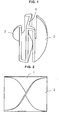
- Fig. 1 is a perspective view to illustrate one example of the mixing element according to the present invention.
- Fig. 2 is a left side view of Fig. 1 .
- Fig. 3 is a plan view of Fig. 1 .
- Fig. 4 is a front view of Fig. 1 .
- Fig. 5 is a perspective view to illustrate another example of the mixing element according to the present invention having portions for engaging end parts at an end part thereof.
- Fig. 6 is a perspective view to illustrate further another example of the mixing element according to the present invention.
- Fig. 7 is a side view to illustrate a state that a plurality of mixing elements in Fig. 1 are connected and provided in a casing.
- Fig. 8 is a side view to illustrate a state that a mixing element in Fig. 1 , which is cut orthogonally to an axial direction of a casing, is provided at the inlet side of a casing.
- a casing C in the drawings has a cylindrical tube shape or a square tube shape.
- Mixing elements according to the present invention are arranged in the casing C in a state that adj acent end parts of the mixing elements are connected so as to be almost orthogonally crossed. It is preferable that the casing C is transparent or semitransparent in order to observe the inside thereof, as illustrated in Figs. 7 and 8 .
- a partition wall part 1 having a thin flat plate shape partitions a cross section of the casing C so as to have approximately equal areas when the mixing element is provided in the casing C.
- the cross section of the casing C is partitioned to have approximately equal areas by the partition wall part 1 in order to equally mix various kinds of fluids poured into the casing C. Further, in order to more equally mix various kinds of fluids, it is preferable that the cross section of the casing C is partitioned so as to have an approximately same shape, in addition to that the cross section of the casing C is partitioned so as to have an approximately equal area.
- the mixing element as illustrated in Figs.
- the partition wall part 1 is provided so as to make a circular cross section in the casing C to be semicircles respectively.
- the cross section in the casing C is partitioned by the partition wall part 1 so as to have an approximately equal area and an approximately same shape, unevenness in mixing does not arise.
- the mixing element as illustrated in Fig. 6 is used in the casing C having a square tube shape, it is preferable that two partition wall parts 1 and 1 are provided so that a cross section in the casing C is partitioned so as to have equal areas and a same rectangular shape.
- a spiral blade part 2 has a shape in which a thin plate is twisted by approximately 180 degrees toward an axial direction of the casing C, and an outer periphery of the spiral blade 2 at the partition wall 1 part side is integrally contacted with the partition wall part 1. Further, the spiral blade part 2 is positioned in each space partitioned by the partition wall part 1 in the casing C, and an outer periphery of the spiral part 2 at the casing C side is contacted with an inner wall of the casing C along the whole length of each space.
- the mixing element according to the present invention has a plurality of such the spiral blade parts 2, .... As for a conventional mixer, since one mixing element has only one spiral blade part , fluids are divided only into two.
- each mixing element has one spiral blade part, and stirring effect is obtained by alternately connecting mixing elements having a clockwise spiral blade part and mixing elements having a counterclockwise spiral blade part for reversing a rotating direction of fluids.
- the mixing element according to the present invention has a plurality of spiral blade parts 2, ... .
- One mixing element can have mixedly clockwise and counterclockwise spiral blade parts 2 ... .
- the mixing elements having clockwise and counterclockwise spiral blade parts 2 ... mixedly are connected so that end parts are almost orthogonally crossed, there occurs a case that a rotating direction of a part of fluids is not reversed at the end part of the mixing element, but is rotated in the same direction. Thus, stirring property may be deteriorated.
- the mixing element according to the present invention may have a complicated shape since it includes the partition wall part 1 and a plurality of the spiral blade parts 2 ... , so that it is hard to integrally form a plurality of such the mixing elements in a state of being connected. Therefore, mixing elements each of which has portions 3 for engaging end parts at the end parts to be adjacent in an axial direction of the casing C, as illustrated in Fig. 5 are separately produced. By connecting and fixing such the mixing elements, it becomes remarkably easy to produce mixing elements.
- the mixing element includes the portions 3 for engaging the end parts, static mixers having various lengths according to intended uses can be easily produced. Thus, such is preferable.
- a prism-shaped small projection may be formed at a center part of the partition wall part 1 as illustrated in Fig. 5 , and an engaging hole (not illustrated) to be engaged with the small projection may be formed at a center part of the partition wall part 1 at the opposite side to the small projection.
- the fluids may not be smoothly divided at the inlet side of the casing C where the fluids are poured.
- a mixing element which is cut in a direction orthogonal to an axial direction of the casing C may be provided at the inlet side of the casing C as illustrated in Fig. 8 .
Abstract
Description
- The present invention relates to mixing elements of a Kenix type static mixer having spiral blades arranged in a casing. The spiral blades respectively have a shape twisted by approximately 180 degrees in an axial direction of the casing and end parts of the blades are connected so as to be almost orthogonally crossed.
- When fluids are mixed, a static mixer not having a driving part is widely used. For example, there exists a mixer having a cylindrical casing, mixing elements respectively having a clockwise spiral blade, and mixing elements respectively having a counterclockwise spiral blade. Both kinds of the mixing elements respectively have a shape twisted by approximately 180 degrees in an axial direction. End parts of adjacent spiral blades are connected so as to cross almost orthogonally and both kinds of the mixing elements are alternately arranged in the axial direction (Refer to
U.S Patent No. 3953002 andU.S. Patent No. 4408893 for example). - Such the static mixer is generally called as a Kenix type static mixer. Two separated spiral flowing passages are formed with the twisted spiral blades (the mixing elements) arranged in a casing and an inner wall of the casing, and fluids pass through these flowing passages so as to be divided into two. In the Kenix static mixer, such the division is repeated, and thus a mixed state can be made.
- However, since the fluids are divided only into two by every mixing element, many mixing elements are necessary in order to sufficiently divide and make a mixed state. For example, when the fluids are divided into 1000 or more, about 10 to 12 mixing elements (to divide the fluids into 1024 (210) to 4096 (212)) are necessary. Therefore, in the conventional Kenix type static mixer, there are disadvantages that many mixing elements must be arranged in a casing so as to make it in an elongated size, and much fluids remain in the casing after use, which is wasteful.
- On the other hand, there is a so-called SMX type static mixer having a plurality of mixing elements in a casing. Each mixing element consists of comb-shaped discs provided with slits and the discs cross with each other at these slit portions (Refer to
U.S. Patent No. 4062524 for example). The SMX type static mixer has many flow inlets formed at a portion where the comb-shaped slits in the discs are crossed. Thus, since fluids can be divided into many only by providing fewer mixing elements in comparison with the Kenix type static mixer, the size is not elongated. - However, for the SMX type static mixer, it is necessary that the comb-shaped slits are formed in the discs constituting the mixing element and the discs are arranged in the casing in the state that the discs are crossed. Thus, a comparatively large casing is necessary, so that the disadvantage that much fluids remain in the casing is not solved. Further, in the SMX type static mixer, fluids tend to follow straight, since they only pass through small flow inlets formed at the crossing part of the slits. Thus, there is a disadvantage that mixing performance is lower than the Kenix static mixer in which fluids pass through the spiral flowing passage.
- The present invention is made to solve these problems, and an objective of the present invention is to provide mixing elements of a Kenix type static mixer, which is not elongated in a size of the casing and is thus capable of decreasing fluids remaining in the casing wastefully.
- Present inventors carried out earnest works to solve the above-described problems and, as a result they found out the followings to complete the present invention. Mixing elements of a static mixer are arranged in a casing so that their end parts adjacent in an axial direction of a casing having a cylindrical or square tube shape are connected so as to be almost orthogonally crossed. Each of the mixing elements includes a partition wall part having a thin flat plate shape, and a plurality of spiral blade parts. The partition wall part partitions a cross section of the casing so as to have approximately equal areas when the mixing element is provided in the casing. The spiral blade parts respectively have a shape in which a thin plate is twisted by approximately 180 degrees toward an axial direction of the casing, and outer peripheries of the spiral blade parts at the partition wall part side are integrally contacted with the partition wall part. The spiral blade parts are respectively positioned in each space partitioned by the partition wall part in the casing, and outer peripheries of the spiral blade parts at the casing side are contacted with an inner wall of the casing along the whole length of each space. In a conventional Kenix type static mixer, fluids are divided into two by every mixing element. However, according to the invention, since each mixing element has a plurality of spiral blade parts, one mixing element can make division into many. Thus, since many mixing elements are not necessary, the size of the casing is not elongated. Further, in a conventional Kenix static mixer, since the two separated flowing passages are formed between the spiral blade parts and the inner wall of the casing, the fluids flowing in the respective passages are not mixed during flow. Then, if a plurality of spiral blade parts are merely arranged in order to make it possible to divide fluids into many by one mixing element, the fluids are mixed between adjacent spiral blade parts. Thus, there occurs a new problem that an effect to divide fluids into many by arranging a plurality of the spiral blade parts is lost. However, the mixing element according to the present invention is formed to have the structure that the partition wall part in a thin flat plate shape to partition the cross section of the casing so as to have approximately equal areas is integrated with each spiral blade part. Therefore, since a plurality of the spiral blade parts form separated flowing passages with not only the inner wall of the casing but also the partition wall part, divided fluids are not mixed during flow. Furthermore, since the partition wall part is to partition the cross section of the casing so as to have approximately equal areas, an amount of fluids divided by each spiral blade part is equal. Thus, the fluids flowing in the casing can be well mixed.
- That is, the present invention is mixing elements of a static mixer, which are arranged in a casing so that their end parts adjacent in an axial direction of the casing having a cylindrical or square tube shape are connected so as to be almost orthogonally crossed. The mixing element of a static mixer includes a partition wall part having a thin flat plate shape, and a plurality of spiral blade parts. The partition wall part partitions a cross section of the casing so as to have approximately equal areas when the mixing element is provided in the casing. The spiral blade parts respectively have a shape in which a thin plate is twisted by approximately 180 degrees toward an axial direction of the casing, and outer peripheries of the spiral blade parts at the partition wall part side are integrally contacted with the partition wall part. The spiral blade parts are respectively positioned in each space partitioned by the partition wall part in the casing, and outer peripheries of the spiral blade parts at the casing side are contacted with an inner wall of the casing along the whole length of each space.
- Further, while the mixing element according to the present invention includes a plurality of spiral blade parts, clockwise and counterclockwise spiral blade parts can be mixedly used in one mixing element. However, when all spiral blade parts of one mixing element are twisted in the same direction, it is easy to produce the mixing element. When the mixing elements in which all spiral blade parts of one mixing element are twisted in the same direction (e.g., in the clockwise direction) are arranged in the casing in a state that their end parts adjacent in an axial direction of the casing are connected so as to be almost orthogonally crossed, fluids are divided into many at one time in each mixing element, and thus mixing efficiency of fluids is high. However, when mixing elements having only clockwise spiral blade parts and mixing elements having only counterclockwise spiral blade parts are alternately connected, a rotating direction of fluids is reversed for every mixing element. Thus, stirring performance can be made high, so that such is preferable. Further, when the mixing element includes portions to engage the end parts at the end parts to be adj acent in an axial direction of the casing, it is not necessary to produce a set of mixing elements in which a plurality of mixing elements are integrally connected so as to have a length corresponding to the length of a casing. Instead, by engaging the adjacent end parts of the mixing elements, it is easy to produce a static mixer having a desired length in combination of various mixing elements according to an intended use. Thus, such is preferable.
- The mixing elements according to the present invention are a mixing elements of a static mixer arranged in a casing so that end parts adjacent in an axial direction of a casing having a cylindrical or square tube shape are connected so as to be almost orthogonally crossed. The mixing element of a static mixer includes a partition wall part having a thin flat plate shape, and a plurality of spiral blade parts. The partition wall part partitions a cross section of the casing so as to have approximately equal areas when the mixing element is provided in the casing. The spiral blade parts respectively have a shape in which a thin plate is twisted by approximately 180 degrees toward an axial direction of the casing, and outer peripheries of spiral blade parts at the partition wall part side are integrally contacted with the partition wall part. The spiral blade parts are respectively positioned in each space partitioned by the partition wall part in the casing, and outer peripheries of the spiral blade parts at the casing side are contacted with an inner wall of the casing along the whole length of each space. In a conventional Kenix type static mixer, fluids are divided into two by every mixing element. However, as for the mixing element according to the present invention, since each mixing element has a plurality of spiral blade parts, the fluids can be divided into many at one time. Thus, since many mixing elements are not necessary, the size of the casing is not elongated. Further, the mixing element according to the present invention is formed to have the structure that the partition wall part in a thin flat plate shape to partition the cross section of the casing so as to have approximately equal areas is integrated with each spiral blade part. Therefore, since a plurality of the spiral blade parts form separated flowing passages having equal cross sections with the inner wall of the casing and the partition wall part, divided fluids are not mixed during flow, and fluids can be equally divided by only using a few mixing elements. Thus, fluids wastefully remaining in a casing after use can be decreased.
- Further, when the mixing elements in which all spiral blade parts of one mixing element are twisted in the same direction (e.g., in the clockwise direction) are arranged in the casing in a state that the end parts adjacent in an axial direction of the casing are connected so as to be almost orthogonally crossed, fluids are divided into many at one time in each mixing element, and thus mixing efficiency of fluids is high. However, when mixing elements having only clockwise spiral blade parts and mixing elements having only counterclockwise spiral blade parts are alternately connected, a rotating direction of fluids is reversed for every mixing element. Thus, stirring performance can be made high. Further, when the mixing element includes portions for engaging the end parts at the end parts to be adjacent in an axial direction of the casing, it is not necessary to produce a set of mixing elements in which a plurality of mixing elements are integrally connected so as to have a length corresponding to have the length of a casing. Instead, by engaging these adjacent end parts of the mixing elements, it is easy to produce a static mixer having a desired length in combination of various mixing elements according to an intended use.
-
Fig. 1 is a perspective view to illustrate one example of the mixing element according to the present invention. -
Fig. 2 is a left side view ofFig. 1 . -
Fig. 3 is a plan view ofFig. 1 . -
Fig. 4 is a front view ofFig. 1 . -
Fig. 5 is a perspective view to illustrate another example of the mixing element according to the present invention having portions for engaging end parts at an end part thereof. -
Fig. 6 is a perspective view to illustrate further another example of the mixing element according to the present invention. -
Fig. 7 is a side view to illustrate a state that a plurality of mixing elements inFig. 1 are connected and provided in a casing. -
Fig. 8 is a side view to illustrate a state that a mixing element inFig. 1 , which is cut orthogonally to an axial direction of a casing, is provided at the inlet side of a casing. - The mixing elements according to the present invention will be described in detail below with reference to the drawings.
-
Fig. 1 is a perspective view to illustrate one example of the mixing element according to the present invention.Fig. 2 is a left side view ofFig. 1 .Fig. 3 is a plan view ofFig. 1 .Fig. 4 is a front view ofFig. 1 .Fig. 5 is a perspective view to illustrate another example of the mixing element according to the present invention having portions for engaging end parts at an end part thereof.Fig. 6 is a perspective view to illustrate further another example of the mixing element according to the present invention.Fig. 7 is a side view to illustrate a state that a plurality of mixing elements inFig. 1 are connected and provided in a casing.Fig. 8 is a side view to illustrate a state that a mixing element inFig. 1 , which is cut orthogonally to an axial direction of a casing, is provided at the inlet side of a casing. - A casing C in the drawings has a cylindrical tube shape or a square tube shape. Mixing elements according to the present invention are arranged in the casing C in a state that adj acent end parts of the mixing elements are connected so as to be almost orthogonally crossed. It is preferable that the casing C is transparent or semitransparent in order to observe the inside thereof, as illustrated in
Figs. 7 and 8 . - A
partition wall part 1 having a thin flat plate shape partitions a cross section of the casing C so as to have approximately equal areas when the mixing element is provided in the casing C. The cross section of the casing C is partitioned to have approximately equal areas by thepartition wall part 1 in order to equally mix various kinds of fluids poured into the casing C. Further, in order to more equally mix various kinds of fluids, it is preferable that the cross section of the casing C is partitioned so as to have an approximately same shape, in addition to that the cross section of the casing C is partitioned so as to have an approximately equal area. For example, the mixing element as illustrated inFigs. 1 to 4 is provided in the casing C having a cylindrical tube shape, and thepartition wall part 1 is provided so as to make a circular cross section in the casing C to be semicircles respectively. Thus, since the cross section in the casing C is partitioned by thepartition wall part 1 so as to have an approximately equal area and an approximately same shape, unevenness in mixing does not arise. Further, when the mixing element as illustrated inFig. 6 is used in the casing C having a square tube shape, it is preferable that twopartition wall parts - A
spiral blade part 2 has a shape in which a thin plate is twisted by approximately 180 degrees toward an axial direction of the casing C, and an outer periphery of thespiral blade 2 at thepartition wall 1 part side is integrally contacted with thepartition wall part 1. Further, thespiral blade part 2 is positioned in each space partitioned by thepartition wall part 1 in the casing C, and an outer periphery of thespiral part 2 at the casing C side is contacted with an inner wall of the casing C along the whole length of each space. The mixing element according to the present invention has a plurality of such thespiral blade parts 2, .... As for a conventional mixer, since one mixing element has only one spiral blade part , fluids are divided only into two. However, for example, when one mixing element of the present invention has twospiral blade parts - Further, in a conventional Kenix type static mixer, each mixing element has one spiral blade part, and stirring effect is obtained by alternately connecting mixing elements having a clockwise spiral blade part and mixing elements having a counterclockwise spiral blade part for reversing a rotating direction of fluids.
- On other hand, the mixing element according to the present invention has a plurality of
spiral blade parts 2, ... . One mixing element can have mixedly clockwise and counterclockwisespiral blade parts 2 ... . However, when the mixing elements having clockwise and counterclockwisespiral blade parts 2 ... mixedly are connected so that end parts are almost orthogonally crossed, there occurs a case that a rotating direction of a part of fluids is not reversed at the end part of the mixing element, but is rotated in the same direction. Thus, stirring property may be deteriorated. - When all spiral
blade parts 2 ... of one mixing element are thus twisted in the same direction, it is easy to produce the mixing element. Further, when mixing elements havingspiral blade parts 2, ... all of which are twisted clockwise and mixing elements havingspiral blade parts 2, ... all of which are twisted counterclockwise are alternately connected, a rotating direction of fluids is reversed for every mixing element. Thus, since stirring performance can be made high, such is preferable. - Further, the mixing element according to the present invention may have a complicated shape since it includes the
partition wall part 1 and a plurality of thespiral blade parts 2 ... , so that it is hard to integrally form a plurality of such the mixing elements in a state of being connected. Therefore, mixing elements each of which hasportions 3 for engaging end parts at the end parts to be adjacent in an axial direction of the casing C, as illustrated inFig. 5 are separately produced. By connecting and fixing such the mixing elements, it becomes remarkably easy to produce mixing elements. - Further, when the mixing element includes the
portions 3 for engaging the end parts, static mixers having various lengths according to intended uses can be easily produced. Thus, such is preferable. - In addition, as for the
portions 3 for engaging the end parts, a prism-shaped small projection may be formed at a center part of thepartition wall part 1 as illustrated inFig. 5 , and an engaging hole (not illustrated) to be engaged with the small projection may be formed at a center part of thepartition wall part 1 at the opposite side to the small projection. - Furthermore, when high viscosity fluids are mixed, the fluids may not be smoothly divided at the inlet side of the casing C where the fluids are poured. In such the case, a mixing element which is cut in a direction orthogonal to an axial direction of the casing C may be provided at the inlet side of the casing C as illustrated in
Fig. 8 .
Claims (3)
- Mixing elements of a static mixer, which are arranged in a casing (C) so that their end parts adj acent in an axial direction of the casing (C) having a cylindrical or square tube shape are connected so as to be almost orthogonally crossed,
the mixing element comprising:a partition wall part (1) having a thin flat plate shape; anda plurality of spiral blade parts (2, ...),wherein the partition wall part (1) partitions a cross section of the casing (C) so as to have approximately equal areas when the mixing element is provided in the casing (C),
wherein the spiral blade parts (2, ...) respectively have a shape in which a thin plate is twisted by approximately 180 degrees toward an axial direction of the casing (C),
wherein outer peripheries of the spiral blade parts (2, ...) at thepartitionwall part (1) side are integrally contacted with the partition wall part (1),
wherein the spiral blade parts (2, ...) are respectively positioned in each space partitioned by the partition wall part (1) in the casing (C), and
wherein outer peripheries of the spiral blade parts (2, ...) at the casing (C) side are contacted with an inner wall of the casing (C) along the whole length of each space. - The mixing elements of a static mixer as claimed in claim 1, wherein all of the spiral blade parts (2, ...) are twisted in the same direction.
- The mixing elements of a static mixer as claimed in claim 1 or 2, wherein the mixing element further includes portions (3) for engaging the end parts adjacent in an axial direction of the casing (C).
Applications Claiming Priority (1)
| Application Number | Priority Date | Filing Date | Title |
|---|---|---|---|
| JP2007292219A JP4987673B2 (en) | 2007-11-09 | 2007-11-09 | Static mixer mixing element |
Publications (2)
| Publication Number | Publication Date |
|---|---|
| EP2058048A1 true EP2058048A1 (en) | 2009-05-13 |
| EP2058048B1 EP2058048B1 (en) | 2011-01-12 |
Family
ID=40342565
Family Applications (1)
| Application Number | Title | Priority Date | Filing Date |
|---|---|---|---|
| EP08019536A Not-in-force EP2058048B1 (en) | 2007-11-09 | 2008-11-07 | Mixing elements for a static mixer |
Country Status (5)
| Country | Link |
|---|---|
| US (1) | US20090122638A1 (en) |
| EP (1) | EP2058048B1 (en) |
| JP (1) | JP4987673B2 (en) |
| AT (1) | ATE494944T1 (en) |
| DE (1) | DE602008004402D1 (en) |
Cited By (4)
| Publication number | Priority date | Publication date | Assignee | Title |
|---|---|---|---|---|
| CN102029121A (en) * | 2009-09-25 | 2011-04-27 | 诺信公司 | Cross flow inversion baffle for static mixer |
| CN108430615A (en) * | 2015-11-13 | 2018-08-21 | 雷米克瑟斯公司 | Static mixer |
| CN108531723A (en) * | 2018-05-24 | 2018-09-14 | 芜湖新兴铸管有限责任公司 | Improve the mixed structure of mixing machine balling ratio |
| CN111195486A (en) * | 2018-11-16 | 2020-05-26 | 中国石油化工股份有限公司 | Static mixer |
Families Citing this family (12)
| Publication number | Priority date | Publication date | Assignee | Title |
|---|---|---|---|---|
| US9498271B2 (en) * | 2009-10-29 | 2016-11-22 | Cook Medical Technologies Llc | Coaxial needle cannula with distal spiral mixer and side ports for fluid injection |
| US10420888B2 (en) * | 2013-09-03 | 2019-09-24 | Max Arocha | Double-chamber mixing syringe and method of use |
| EP3034159B1 (en) * | 2014-12-18 | 2020-11-04 | The Procter and Gamble Company | Static mixer and method of mixing fluids |
| CN105984967A (en) * | 2015-01-27 | 2016-10-05 | 无锡市兴盛环保设备有限公司 | Novel fixed spiral aeration device |
| CN104645841A (en) * | 2015-03-13 | 2015-05-27 | 汤裕浩 | Static mixer unit |
| US10729600B2 (en) | 2015-06-30 | 2020-08-04 | The Procter & Gamble Company | Absorbent structure |
| PL3370664T3 (en) | 2015-11-04 | 2022-03-07 | The Procter & Gamble Company | Absorbent article comprising an absorbent structure |
| WO2017079599A1 (en) | 2015-11-04 | 2017-05-11 | The Procter & Gamble Company | Absorbent structure |
| US20180056251A1 (en) * | 2016-08-30 | 2018-03-01 | Moldman Systems Llc | Stackable static mixing elements |
| EP3676534B1 (en) * | 2017-09-01 | 2022-01-05 | Metso Outotec Finland Oy | Burner feed mixture distribution device |
| KR101922535B1 (en) * | 2018-01-05 | 2018-11-28 | 사빅 에스케이 넥슬렌 컴퍼니 피티이 엘티디 | Mixing system including extensional mixing element |
| WO2021081122A1 (en) * | 2019-10-21 | 2021-04-29 | Re Mixers, Inc | Static mixer |
Citations (7)
| Publication number | Priority date | Publication date | Assignee | Title |
|---|---|---|---|---|
| US3953002A (en) | 1973-09-21 | 1976-04-27 | England Jr Herbert C | Motionless mixing device |
| US4062524A (en) | 1973-06-06 | 1977-12-13 | Bayer Aktiengesellschaft | Apparatus for the static mixing of fluid streams |
| US4408893A (en) | 1982-04-28 | 1983-10-11 | Luwa A.G. | Motionless mixing device |
| EP0584428A1 (en) * | 1992-08-24 | 1994-03-02 | Wilhelm A. Keller | Mixer for double dispensing cartridges |
| EP1426099A1 (en) * | 2002-12-06 | 2004-06-09 | Mixpac Systems AG | Static mixer |
| WO2006039827A1 (en) * | 2004-10-15 | 2006-04-20 | Medmix Systems Ag | Static mixer |
| DE202006012130U1 (en) * | 2006-08-08 | 2006-12-07 | Ritter Gmbh | Helical static mixer is made up of rectangular, especially square plates, each of which is turned through angle with respect to preceding one, mixer being mounted in pipe |
Family Cites Families (5)
| Publication number | Priority date | Publication date | Assignee | Title |
|---|---|---|---|---|
| JPS5339869U (en) * | 1976-09-10 | 1978-04-06 | ||
| JP2681736B2 (en) * | 1993-03-09 | 1997-11-26 | 株式会社ノリタケカンパニーリミテド | Filler for mixing and dispersing |
| JPH1190197A (en) * | 1997-09-26 | 1999-04-06 | Anico Ind Co Ltd | Multi-static mixing system |
| JP2001120973A (en) * | 1999-10-29 | 2001-05-08 | Fuyo Sangyo Kk | In-line mixer |
| JP2003014210A (en) * | 2001-06-28 | 2003-01-15 | Bena:Kk | Combustion burner and mixer for combustion burner |
-
2007
- 2007-11-09 JP JP2007292219A patent/JP4987673B2/en active Active
-
2008
- 2008-11-07 DE DE602008004402T patent/DE602008004402D1/en active Active
- 2008-11-07 EP EP08019536A patent/EP2058048B1/en not_active Not-in-force
- 2008-11-07 AT AT08019536T patent/ATE494944T1/en not_active IP Right Cessation
- 2008-11-07 US US12/266,833 patent/US20090122638A1/en not_active Abandoned
Patent Citations (7)
| Publication number | Priority date | Publication date | Assignee | Title |
|---|---|---|---|---|
| US4062524A (en) | 1973-06-06 | 1977-12-13 | Bayer Aktiengesellschaft | Apparatus for the static mixing of fluid streams |
| US3953002A (en) | 1973-09-21 | 1976-04-27 | England Jr Herbert C | Motionless mixing device |
| US4408893A (en) | 1982-04-28 | 1983-10-11 | Luwa A.G. | Motionless mixing device |
| EP0584428A1 (en) * | 1992-08-24 | 1994-03-02 | Wilhelm A. Keller | Mixer for double dispensing cartridges |
| EP1426099A1 (en) * | 2002-12-06 | 2004-06-09 | Mixpac Systems AG | Static mixer |
| WO2006039827A1 (en) * | 2004-10-15 | 2006-04-20 | Medmix Systems Ag | Static mixer |
| DE202006012130U1 (en) * | 2006-08-08 | 2006-12-07 | Ritter Gmbh | Helical static mixer is made up of rectangular, especially square plates, each of which is turned through angle with respect to preceding one, mixer being mounted in pipe |
Cited By (12)
| Publication number | Priority date | Publication date | Assignee | Title |
|---|---|---|---|---|
| CN102029121A (en) * | 2009-09-25 | 2011-04-27 | 诺信公司 | Cross flow inversion baffle for static mixer |
| EP2301656A3 (en) * | 2009-09-25 | 2012-06-06 | Nordson Corporation | Cross Flow Inversion Baffle For Static Mixer |
| CN102029121B (en) * | 2009-09-25 | 2014-08-27 | 诺信公司 | Cross flow inversion baffle for static mixer |
| CN108430615A (en) * | 2015-11-13 | 2018-08-21 | 雷米克瑟斯公司 | Static mixer |
| EP3374070A4 (en) * | 2015-11-13 | 2019-07-17 | Re Mixers, Inc. | Static mixer |
| US10898872B2 (en) | 2015-11-13 | 2021-01-26 | Re Mixers, Inc. | Static mixer |
| CN108430615B (en) * | 2015-11-13 | 2021-06-25 | 雷米克瑟斯公司 | Static mixer |
| CN113477115A (en) * | 2015-11-13 | 2021-10-08 | 雷米克瑟斯公司 | Static mixer |
| US11786876B2 (en) | 2015-11-13 | 2023-10-17 | Re Mixers, Inc. | Static mixer |
| CN113477115B (en) * | 2015-11-13 | 2023-12-05 | 雷米克瑟斯公司 | Static mixer |
| CN108531723A (en) * | 2018-05-24 | 2018-09-14 | 芜湖新兴铸管有限责任公司 | Improve the mixed structure of mixing machine balling ratio |
| CN111195486A (en) * | 2018-11-16 | 2020-05-26 | 中国石油化工股份有限公司 | Static mixer |
Also Published As
| Publication number | Publication date |
|---|---|
| EP2058048B1 (en) | 2011-01-12 |
| ATE494944T1 (en) | 2011-01-15 |
| JP4987673B2 (en) | 2012-07-25 |
| JP2009113012A (en) | 2009-05-28 |
| US20090122638A1 (en) | 2009-05-14 |
| DE602008004402D1 (en) | 2011-02-24 |
Similar Documents
| Publication | Publication Date | Title |
|---|---|---|
| EP2058048A1 (en) | Mixing elements for a static mixer | |
| US4643584A (en) | Motionless mixer | |
| EP2349548B1 (en) | Static mixer | |
| CN101056697B (en) | Static mixer | |
| US20010012235A1 (en) | Static mixer | |
| ES2232559T3 (en) | STATIC MIXER. | |
| CN106390802B (en) | Dynamic mixer joint | |
| JPWO2005077506A1 (en) | Mixing element and static fluid mixer using the same | |
| BR112013015378B1 (en) | dynamic mixer for a variety of fluid components | |
| WO2015171997A1 (en) | Static mixer | |
| EP1923127A2 (en) | Mixing element | |
| JP2020526386A (en) | Static mixer with triangular mixing conduit | |
| EP2428341A2 (en) | Mixer axis for dual axis concrete mixer, and dual axis concrete mixer | |
| JP2015202438A (en) | Rotary mixer in multi-liquid mixing type injector | |
| JP5149368B2 (en) | Mixing element and static fluid mixer using the same | |
| CA2350944C (en) | Mixer for mixing gases and other newtonian liquids | |
| US3462131A (en) | Mixing device | |
| DK149324B (en) | FLOW MIXER WITHOUT MOVING PARTS | |
| CN114053920B (en) | Micro mixer | |
| JP2005034750A (en) | Fluid agitating apparatus | |
| JPH03193128A (en) | Pipeline mixer | |
| CN112808053A (en) | Static mixer | |
| JP7252423B2 (en) | Liquid mixing impeller and mixing device | |
| KR101135614B1 (en) | Mixing Element for Static Mixer and Static Mixer Using the Same | |
| CN214513854U (en) | Static mixer |
Legal Events
| Date | Code | Title | Description |
|---|---|---|---|
| PUAI | Public reference made under article 153(3) epc to a published international application that has entered the european phase |
Free format text: ORIGINAL CODE: 0009012 |
|
| AK | Designated contracting states |
Kind code of ref document: A1 Designated state(s): AT BE BG CH CY CZ DE DK EE ES FI FR GB GR HR HU IE IS IT LI LT LU LV MC MT NL NO PL PT RO SE SI SK TR |
|
| AX | Request for extension of the european patent |
Extension state: AL BA MK RS |
|
| 17P | Request for examination filed |
Effective date: 20090917 |
|
| 17Q | First examination report despatched |
Effective date: 20091016 |
|
| AKX | Designation fees paid |
Designated state(s): AT BE BG CH CY CZ DE DK EE ES FI FR GB GR HR HU IE IS IT LI LT LU LV MC MT NL NO PL PT RO SE SI SK TR |
|
| GRAP | Despatch of communication of intention to grant a patent |
Free format text: ORIGINAL CODE: EPIDOSNIGR1 |
|
| GRAS | Grant fee paid |
Free format text: ORIGINAL CODE: EPIDOSNIGR3 |
|
| GRAA | (expected) grant |
Free format text: ORIGINAL CODE: 0009210 |
|
| AK | Designated contracting states |
Kind code of ref document: B1 Designated state(s): AT BE BG CH CY CZ DE DK EE ES FI FR GB GR HR HU IE IS IT LI LT LU LV MC MT NL NO PL PT RO SE SI SK TR |
|
| REG | Reference to a national code |
Ref country code: GB Ref legal event code: FG4D |
|
| REG | Reference to a national code |
Ref country code: CH Ref legal event code: EP |
|
| REG | Reference to a national code |
Ref country code: IE Ref legal event code: FG4D |
|
| REF | Corresponds to: |
Ref document number: 602008004402 Country of ref document: DE Date of ref document: 20110224 Kind code of ref document: P |
|
| REG | Reference to a national code |
Ref country code: DE Ref legal event code: R096 Ref document number: 602008004402 Country of ref document: DE Effective date: 20110224 |
|
| REG | Reference to a national code |
Ref country code: NL Ref legal event code: VDEP Effective date: 20110112 |
|
| LTIE | Lt: invalidation of european patent or patent extension |
Effective date: 20110112 |
|
| PG25 | Lapsed in a contracting state [announced via postgrant information from national office to epo] |
Ref country code: IS Free format text: LAPSE BECAUSE OF FAILURE TO SUBMIT A TRANSLATION OF THE DESCRIPTION OR TO PAY THE FEE WITHIN THE PRESCRIBED TIME-LIMIT Effective date: 20110512 Ref country code: ES Free format text: LAPSE BECAUSE OF FAILURE TO SUBMIT A TRANSLATION OF THE DESCRIPTION OR TO PAY THE FEE WITHIN THE PRESCRIBED TIME-LIMIT Effective date: 20110423 Ref country code: GR Free format text: LAPSE BECAUSE OF FAILURE TO SUBMIT A TRANSLATION OF THE DESCRIPTION OR TO PAY THE FEE WITHIN THE PRESCRIBED TIME-LIMIT Effective date: 20110413 Ref country code: LT Free format text: LAPSE BECAUSE OF FAILURE TO SUBMIT A TRANSLATION OF THE DESCRIPTION OR TO PAY THE FEE WITHIN THE PRESCRIBED TIME-LIMIT Effective date: 20110112 Ref country code: LV Free format text: LAPSE BECAUSE OF FAILURE TO SUBMIT A TRANSLATION OF THE DESCRIPTION OR TO PAY THE FEE WITHIN THE PRESCRIBED TIME-LIMIT Effective date: 20110112 Ref country code: NO Free format text: LAPSE BECAUSE OF FAILURE TO SUBMIT A TRANSLATION OF THE DESCRIPTION OR TO PAY THE FEE WITHIN THE PRESCRIBED TIME-LIMIT Effective date: 20110412 Ref country code: SE Free format text: LAPSE BECAUSE OF FAILURE TO SUBMIT A TRANSLATION OF THE DESCRIPTION OR TO PAY THE FEE WITHIN THE PRESCRIBED TIME-LIMIT Effective date: 20110112 Ref country code: HR Free format text: LAPSE BECAUSE OF FAILURE TO SUBMIT A TRANSLATION OF THE DESCRIPTION OR TO PAY THE FEE WITHIN THE PRESCRIBED TIME-LIMIT Effective date: 20110112 Ref country code: PT Free format text: LAPSE BECAUSE OF FAILURE TO SUBMIT A TRANSLATION OF THE DESCRIPTION OR TO PAY THE FEE WITHIN THE PRESCRIBED TIME-LIMIT Effective date: 20110512 |
|
| PG25 | Lapsed in a contracting state [announced via postgrant information from national office to epo] |
Ref country code: AT Free format text: LAPSE BECAUSE OF FAILURE TO SUBMIT A TRANSLATION OF THE DESCRIPTION OR TO PAY THE FEE WITHIN THE PRESCRIBED TIME-LIMIT Effective date: 20110112 Ref country code: NL Free format text: LAPSE BECAUSE OF FAILURE TO SUBMIT A TRANSLATION OF THE DESCRIPTION OR TO PAY THE FEE WITHIN THE PRESCRIBED TIME-LIMIT Effective date: 20110112 Ref country code: BG Free format text: LAPSE BECAUSE OF FAILURE TO SUBMIT A TRANSLATION OF THE DESCRIPTION OR TO PAY THE FEE WITHIN THE PRESCRIBED TIME-LIMIT Effective date: 20110412 Ref country code: PL Free format text: LAPSE BECAUSE OF FAILURE TO SUBMIT A TRANSLATION OF THE DESCRIPTION OR TO PAY THE FEE WITHIN THE PRESCRIBED TIME-LIMIT Effective date: 20110112 Ref country code: SI Free format text: LAPSE BECAUSE OF FAILURE TO SUBMIT A TRANSLATION OF THE DESCRIPTION OR TO PAY THE FEE WITHIN THE PRESCRIBED TIME-LIMIT Effective date: 20110112 Ref country code: CY Free format text: LAPSE BECAUSE OF FAILURE TO SUBMIT A TRANSLATION OF THE DESCRIPTION OR TO PAY THE FEE WITHIN THE PRESCRIBED TIME-LIMIT Effective date: 20110112 Ref country code: FI Free format text: LAPSE BECAUSE OF FAILURE TO SUBMIT A TRANSLATION OF THE DESCRIPTION OR TO PAY THE FEE WITHIN THE PRESCRIBED TIME-LIMIT Effective date: 20110112 |
|
| PG25 | Lapsed in a contracting state [announced via postgrant information from national office to epo] |
Ref country code: DK Free format text: LAPSE BECAUSE OF FAILURE TO SUBMIT A TRANSLATION OF THE DESCRIPTION OR TO PAY THE FEE WITHIN THE PRESCRIBED TIME-LIMIT Effective date: 20110112 Ref country code: EE Free format text: LAPSE BECAUSE OF FAILURE TO SUBMIT A TRANSLATION OF THE DESCRIPTION OR TO PAY THE FEE WITHIN THE PRESCRIBED TIME-LIMIT Effective date: 20110112 |
|
| PLBE | No opposition filed within time limit |
Free format text: ORIGINAL CODE: 0009261 |
|
| STAA | Information on the status of an ep patent application or granted ep patent |
Free format text: STATUS: NO OPPOSITION FILED WITHIN TIME LIMIT |
|
| PG25 | Lapsed in a contracting state [announced via postgrant information from national office to epo] |
Ref country code: RO Free format text: LAPSE BECAUSE OF FAILURE TO SUBMIT A TRANSLATION OF THE DESCRIPTION OR TO PAY THE FEE WITHIN THE PRESCRIBED TIME-LIMIT Effective date: 20110112 Ref country code: CZ Free format text: LAPSE BECAUSE OF FAILURE TO SUBMIT A TRANSLATION OF THE DESCRIPTION OR TO PAY THE FEE WITHIN THE PRESCRIBED TIME-LIMIT Effective date: 20110112 Ref country code: SK Free format text: LAPSE BECAUSE OF FAILURE TO SUBMIT A TRANSLATION OF THE DESCRIPTION OR TO PAY THE FEE WITHIN THE PRESCRIBED TIME-LIMIT Effective date: 20110112 |
|
| 26N | No opposition filed |
Effective date: 20111013 |
|
| PG25 | Lapsed in a contracting state [announced via postgrant information from national office to epo] |
Ref country code: IT Free format text: LAPSE BECAUSE OF FAILURE TO SUBMIT A TRANSLATION OF THE DESCRIPTION OR TO PAY THE FEE WITHIN THE PRESCRIBED TIME-LIMIT Effective date: 20110112 |
|
| REG | Reference to a national code |
Ref country code: DE Ref legal event code: R097 Ref document number: 602008004402 Country of ref document: DE Effective date: 20111013 |
|
| BERE | Be: lapsed |
Owner name: GC CORP. Effective date: 20111130 |
|
| PG25 | Lapsed in a contracting state [announced via postgrant information from national office to epo] |
Ref country code: MC Free format text: LAPSE BECAUSE OF NON-PAYMENT OF DUE FEES Effective date: 20111130 |
|
| REG | Reference to a national code |
Ref country code: FR Ref legal event code: ST Effective date: 20120731 |
|
| REG | Reference to a national code |
Ref country code: IE Ref legal event code: MM4A |
|
| PG25 | Lapsed in a contracting state [announced via postgrant information from national office to epo] |
Ref country code: BE Free format text: LAPSE BECAUSE OF NON-PAYMENT OF DUE FEES Effective date: 20111130 |
|
| REG | Reference to a national code |
Ref country code: DE Ref legal event code: R119 Ref document number: 602008004402 Country of ref document: DE Effective date: 20120601 |
|
| PG25 | Lapsed in a contracting state [announced via postgrant information from national office to epo] |
Ref country code: IE Free format text: LAPSE BECAUSE OF NON-PAYMENT OF DUE FEES Effective date: 20111107 |
|
| PG25 | Lapsed in a contracting state [announced via postgrant information from national office to epo] |
Ref country code: FR Free format text: LAPSE BECAUSE OF NON-PAYMENT OF DUE FEES Effective date: 20111130 |
|
| PG25 | Lapsed in a contracting state [announced via postgrant information from national office to epo] |
Ref country code: MT Free format text: LAPSE BECAUSE OF FAILURE TO SUBMIT A TRANSLATION OF THE DESCRIPTION OR TO PAY THE FEE WITHIN THE PRESCRIBED TIME-LIMIT Effective date: 20110112 |
|
| PG25 | Lapsed in a contracting state [announced via postgrant information from national office to epo] |
Ref country code: LU Free format text: LAPSE BECAUSE OF NON-PAYMENT OF DUE FEES Effective date: 20111107 |
|
| PG25 | Lapsed in a contracting state [announced via postgrant information from national office to epo] |
Ref country code: DE Free format text: LAPSE BECAUSE OF NON-PAYMENT OF DUE FEES Effective date: 20120601 |
|
| REG | Reference to a national code |
Ref country code: CH Ref legal event code: PL |
|
| GBPC | Gb: european patent ceased through non-payment of renewal fee |
Effective date: 20121107 |
|
| PG25 | Lapsed in a contracting state [announced via postgrant information from national office to epo] |
Ref country code: CH Free format text: LAPSE BECAUSE OF NON-PAYMENT OF DUE FEES Effective date: 20121130 Ref country code: LI Free format text: LAPSE BECAUSE OF NON-PAYMENT OF DUE FEES Effective date: 20121130 |
|
| PG25 | Lapsed in a contracting state [announced via postgrant information from national office to epo] |
Ref country code: TR Free format text: LAPSE BECAUSE OF FAILURE TO SUBMIT A TRANSLATION OF THE DESCRIPTION OR TO PAY THE FEE WITHIN THE PRESCRIBED TIME-LIMIT Effective date: 20110112 |
|
| PG25 | Lapsed in a contracting state [announced via postgrant information from national office to epo] |
Ref country code: HU Free format text: LAPSE BECAUSE OF FAILURE TO SUBMIT A TRANSLATION OF THE DESCRIPTION OR TO PAY THE FEE WITHIN THE PRESCRIBED TIME-LIMIT Effective date: 20110112 |
|
| PG25 | Lapsed in a contracting state [announced via postgrant information from national office to epo] |
Ref country code: GB Free format text: LAPSE BECAUSE OF NON-PAYMENT OF DUE FEES Effective date: 20121107 |