EP2058024A1 - Medicine sprayer - Google Patents
Medicine sprayer Download PDFInfo
- Publication number
- EP2058024A1 EP2058024A1 EP07806509A EP07806509A EP2058024A1 EP 2058024 A1 EP2058024 A1 EP 2058024A1 EP 07806509 A EP07806509 A EP 07806509A EP 07806509 A EP07806509 A EP 07806509A EP 2058024 A1 EP2058024 A1 EP 2058024A1
- Authority
- EP
- European Patent Office
- Prior art keywords
- capsule
- insertion hole
- divided member
- posture
- puncture needle
- Prior art date
- Legal status (The legal status is an assumption and is not a legal conclusion. Google has not performed a legal analysis and makes no representation as to the accuracy of the status listed.)
- Granted
Links
- 239000003814 drug Substances 0.000 title claims description 189
- 229940079593 drug Drugs 0.000 title 1
- 239000002775 capsule Substances 0.000 claims abstract description 422
- 238000003780 insertion Methods 0.000 claims abstract description 213
- 230000037431 insertion Effects 0.000 claims abstract description 213
- 238000004804 winding Methods 0.000 claims description 3
- 230000036544 posture Effects 0.000 description 79
- 238000005507 spraying Methods 0.000 description 22
- 239000000843 powder Substances 0.000 description 11
- 210000003928 nasal cavity Anatomy 0.000 description 8
- 238000007789 sealing Methods 0.000 description 8
- 239000007921 spray Substances 0.000 description 6
- 238000003756 stirring Methods 0.000 description 3
- 238000004140 cleaning Methods 0.000 description 1
- 230000006835 compression Effects 0.000 description 1
- 238000007906 compression Methods 0.000 description 1
- 238000007599 discharging Methods 0.000 description 1
- 239000000428 dust Substances 0.000 description 1
- 229920001971 elastomer Polymers 0.000 description 1
- 239000000806 elastomer Substances 0.000 description 1
- 238000000465 moulding Methods 0.000 description 1
- 210000000214 mouth Anatomy 0.000 description 1
- 238000000926 separation method Methods 0.000 description 1
Images


Classifications
-
- A—HUMAN NECESSITIES
- A61—MEDICAL OR VETERINARY SCIENCE; HYGIENE
- A61M—DEVICES FOR INTRODUCING MEDIA INTO, OR ONTO, THE BODY; DEVICES FOR TRANSDUCING BODY MEDIA OR FOR TAKING MEDIA FROM THE BODY; DEVICES FOR PRODUCING OR ENDING SLEEP OR STUPOR
- A61M15/00—Inhalators
- A61M15/0028—Inhalators using prepacked dosages, one for each application, e.g. capsules to be perforated or broken-up
- A61M15/003—Inhalators using prepacked dosages, one for each application, e.g. capsules to be perforated or broken-up using capsules, e.g. to be perforated or broken-up
- A61M15/0033—Details of the piercing or cutting means
- A61M15/0035—Piercing means
-
- A—HUMAN NECESSITIES
- A61—MEDICAL OR VETERINARY SCIENCE; HYGIENE
- A61M—DEVICES FOR INTRODUCING MEDIA INTO, OR ONTO, THE BODY; DEVICES FOR TRANSDUCING BODY MEDIA OR FOR TAKING MEDIA FROM THE BODY; DEVICES FOR PRODUCING OR ENDING SLEEP OR STUPOR
- A61M15/00—Inhalators
- A61M15/0028—Inhalators using prepacked dosages, one for each application, e.g. capsules to be perforated or broken-up
- A61M15/003—Inhalators using prepacked dosages, one for each application, e.g. capsules to be perforated or broken-up using capsules, e.g. to be perforated or broken-up
- A61M15/0033—Details of the piercing or cutting means
- A61M15/0041—Details of the piercing or cutting means with movable piercing or cutting means
-
- A—HUMAN NECESSITIES
- A61—MEDICAL OR VETERINARY SCIENCE; HYGIENE
- A61M—DEVICES FOR INTRODUCING MEDIA INTO, OR ONTO, THE BODY; DEVICES FOR TRANSDUCING BODY MEDIA OR FOR TAKING MEDIA FROM THE BODY; DEVICES FOR PRODUCING OR ENDING SLEEP OR STUPOR
- A61M15/00—Inhalators
- A61M15/08—Inhaling devices inserted into the nose
-
- A—HUMAN NECESSITIES
- A61—MEDICAL OR VETERINARY SCIENCE; HYGIENE
- A61M—DEVICES FOR INTRODUCING MEDIA INTO, OR ONTO, THE BODY; DEVICES FOR TRANSDUCING BODY MEDIA OR FOR TAKING MEDIA FROM THE BODY; DEVICES FOR PRODUCING OR ENDING SLEEP OR STUPOR
- A61M35/00—Devices for applying media, e.g. remedies, on the human body
- A61M35/003—Portable hand-held applicators having means for dispensing or spreading integral media
-
- A—HUMAN NECESSITIES
- A61—MEDICAL OR VETERINARY SCIENCE; HYGIENE
- A61M—DEVICES FOR INTRODUCING MEDIA INTO, OR ONTO, THE BODY; DEVICES FOR TRANSDUCING BODY MEDIA OR FOR TAKING MEDIA FROM THE BODY; DEVICES FOR PRODUCING OR ENDING SLEEP OR STUPOR
- A61M2202/00—Special media to be introduced, removed or treated
- A61M2202/06—Solids
- A61M2202/064—Powder
-
- A—HUMAN NECESSITIES
- A61—MEDICAL OR VETERINARY SCIENCE; HYGIENE
- A61M—DEVICES FOR INTRODUCING MEDIA INTO, OR ONTO, THE BODY; DEVICES FOR TRANSDUCING BODY MEDIA OR FOR TAKING MEDIA FROM THE BODY; DEVICES FOR PRODUCING OR ENDING SLEEP OR STUPOR
- A61M2205/00—General characteristics of the apparatus
- A61M2205/07—General characteristics of the apparatus having air pumping means
- A61M2205/071—General characteristics of the apparatus having air pumping means hand operated
- A61M2205/075—Bulb type
-
- A—HUMAN NECESSITIES
- A61—MEDICAL OR VETERINARY SCIENCE; HYGIENE
- A61M—DEVICES FOR INTRODUCING MEDIA INTO, OR ONTO, THE BODY; DEVICES FOR TRANSDUCING BODY MEDIA OR FOR TAKING MEDIA FROM THE BODY; DEVICES FOR PRODUCING OR ENDING SLEEP OR STUPOR
- A61M2206/00—Characteristics of a physical parameter; associated device therefor
- A61M2206/10—Flow characteristics
- A61M2206/16—Rotating swirling helical flow, e.g. by tangential inflows
Abstract
Description
- This invention relates to a medicine sprayer.
- Conventionally, there are proposed various medicine sprayers. A
patent document 1 discloses one example of the medicine sprayers. - The medicine sprayer of the
above patent document 1 is arranged to form holes in the capsule by a capsule puncture needle, and to discharge a medicine received in the capsule by the air supplied by the pressure. In particular, a medicine spraying portion is screwed in a capsule holder holding a capsule. A capsule puncture needle supported in the medicine spraying portion to be moved in the advancing and returning directions is moved to form the punctures in the capsule.
Patent document 1: Patent No.3273712 - However, in the medicine sprayer of the
patent document 1, the capsule puncture needle held in the medicine spraying portion to be moved in the advancing and returning directions can be moved even in a state in which the medicine sprayer is not screwed in the capsule holder. In this state, if the capsule puncture needle is moved in the advancing and returning directions, the capsule puncture needle is exposed to the outside of the medicine spraying portion, and the dust and the dirt may be adhered to the capsule puncture needle. It is not preferred in the sanitary aspect and the safety aspect. - It is, therefore, an object of the present invention to provide a medicine sprayer devised to solve the above-mentioned problems, and to prevent a capsule puncture needle from being exposed to the outside of the sprayer.
- In the present invention to attain the above-mentioned object, the medicine sprayer includes a first divided member formed with a capsule holding portion holding the capsule; a second divided member including the capsule puncture needle arranged to be moved into or out of the capsule holding portion; the first divided member and the second divided member being connected to be relatively moved at least between a posture in which the capsule holding portion is exposed, and a posture in which the capsule holding portion is hid by the second divided member, the first divided member being arranged to restrict the advancing movement of the capsule puncture needle when the first divided member and the second divided member are in the posture in which the capsule holding portion is exposed. This feature is a first feature according to the present invention. Moreover, the present invention may include second to fourteenth features.
- In the second feature according to the present invention, the first divided member includes a capsule insertion hole serving as the capsule holding portion; the first divided member and the second divided member are connected to be relatively pivoted at least between a posture in which the capsule insertion hole is exposed, and a posture in which the capsule insertion hole is hid; an outlet of the capsule puncture needle from the second divided member confronts an opening portion of the capsule insertion hole when the first divided member and the second divided member are in the posture in which the capsule insertion hole is hid so that the capsule puncture needle is arranged to be moved from the opening portion into the capsule insertion hole; and the outlet confronts an outer side of a side wall when the first divided member and the second divided member are in the posture in which the capsule insertion hole is exposed so that the side wall restricts the advancing movement of the capsule puncture needle.
- In the third feature according to the present invention, the first divided member includes a cylindrical protrusion; the capsule insertion hole is a cylindrical hole of the protrusion; the second divided member includes a pair of arm portions arranged to sandwich the protrusion; one of the protrusion and the arm portions includes a guide groove; the other of the protrusion and the arm portions includes a guide groove arranged to be guided in the guide groove; an end surface of the protrusion and a bottom surface between the pair of the arm portions are abutted on each other when the first divided member and the second divided member are in the posture in which the capsule insertion hole is hid so that the bottom surface closes the opening portion of the capsule insertion hole; the guide groove includes a portion extending in a direction in which the end surface and the bottom surface is abutted on or separated from each other so that the end surface and the bottom surface are separated from each other when the first divided member and the second divided member are changed from the posture in which the capsule insertion hole is hid to the posture in which the capsule insertion hole is exposed.
- In the fourth feature according to the present invention, the first divided member includes a capsule insertion hole serving as the capsule holding portion; the first divided member and the second divided member are connected to be relatively slid at least between a posture in which the capsule insertion hole is exposed, and a posture in which the capsule insertion hole is hid; an outlet of the capsule puncture needle from the second divided member confronts an opening portion of the capsule insertion hole when the first divided member and the second divided member are in the posture in which the capsule insertion hole is hid so that the capsule puncture needle is moved from the opening portion into the capsule insertion hole; and the outlet confronts an upper wall of the capsule insertion hole when the first divided member and the second divided member are in the posture in which the capsule insertion hole is exposed so that the upper wall restricts the advance movement of the capsule puncture needle.
- In the fifth feature according to the present invention, the first divided member includes a cylindrical protrusion; the capsule insertion hole is a cylindrical hole of the protrusion; the second divided member includes a pair of arm portions arranged to sandwich the protrusion; one of protrusion and the arm portion includes a guide groove; the other of the protrusion and the arm portions includes a guide portion arranged to be guided in the guide groove; an end surface of the protrusion and the bottom surface between the pair of the arm portions are abutted on each other when the first divided member and the second divided member are in the posture in which the capsule insertion hole is hid so that the bottom surface closes an opening portion of the capsule insertion hole; the protrusion includes a portion extending in a direction in which the opening portion of the capsule insertion hole and the outlet of the capsule puncture needle are deviated from each other so that the opening portion and the outlet are separated form each other when the first divided member and the second divided member are changed from the posture in which the capsule insertion hole is hid to the posture in which the capsule insertion hole is exposed.
- In the sixth feature according to the present invention, the first divided member include a capsule insertion hole serving as the capsule holding portion; the first divided member and the second divided member are connected to be relatively inclined at least between a posture in which the capsule insertion hole is exposed, and a posture in which the capsule insertion hole is hid; an outlet of the capsule puncture needle from the second divided member confronts an opening portion of the capsule insertion hole when the first divided member and the second divided member are in the posture in which the capsule insertion hole is hid so that the capsule puncture needle is arranged to be moved from the opening portion into the capsule insertion hole; and the outlet confronts an outer side of a side wall of the capsule insertion hole when the first divided member and the second divided member are in the posture in which the capsule insertion hole is exposed so that the side wall restricts the advance movement of the capsule puncture needle.
- In the seventh feature according to the present invention, the first divided member includes a capsule insertion hole serving as the capsule holding portion; the first divided member and the second divided member are connected to be relatively inclined at least between a posture in which the capsule insertion hole is exposed, and a posture in which the capsule insertion hole is hid; an outlet of the capsule puncture needle from the second divided member confronts an opening portion of the capsule insertion hole when the first divided member and the second divided member are in the posture in which the capsule insertion hole is hid so that the capsule puncture needle is arranged to be moved from the opening portion into the capsule insertion hole; the second divided member includes a covering portion arranged to cover the capsule holding portion, and to be moved at a stage before the relative inclination of the first divided member and the second divided member; and the covering portion is arranged to restrict the advance of the capsule puncture needle at the stage before the relative inclination of the first divided member and the second divided member.
- In the eighth feature according to the present invention, the covering portion includes a puncture hole arranged to pass the capsule puncture needle to the capsule insertion hole in the posture in which the capsule insertion hole is hid by the second divided member.
- In the ninth feature according to the present invention, the guide groove includes a portion extending substantially in a direction crossing a direction in which the end surface and the bottom surface are abutted on or separated from each other.
- In the tenth feature according to the present invention, the protrusion is formed into a cylindrical shape; the guide groove and the guide member are provided in a symmetrical manner with respect to a central axis of the protrusion; the guide member is mounted in the guide groove to serve as a pivot axis of the relative pivot of the first divided member and the second divided member.
- In the eleventh feature according to the present invention, the capsule puncture needle is arranged to pass through the capsule held in the capsule insertion hole; a medicine receiving chamber is formed at an end portion of the capsule puncture needle passing through the capsule; the air passage is arranged to introduce the air supplied by the pressure from the air pump mechanism, into the medicine receiving chamber; and the air passage extends in a direction crossing a discharge direction of the medicine and the air from the medicine receiving chamber.
- In the twelfth feature according to the present invention, the capsule holding portion includes a bottom surface formed into a substantially semiround shape which is substantially closely attached to an end portion of the capsule.
- In the thirteenth feature according to the present invention, the medicine receiving chamber is formed into a substantially cylindrical shape extending along an outer shape of the capsule; and the medicine receiving chamber includes a plurality of air passages connected in a tangent direction of an inner cylindrical surface, and arranged in a substantially winding shape.
- In the fourteenth feature according to the present invention, the medicine sprayer further comprises an outer skin section arranged to closely attached to an end portion formed with a discharge hole of the medicine, and to be detachable.
-
-
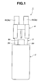
FIG. 1 is a front view showing an appearance of a medicine sprayer according to a first embodiment of the present invention. -
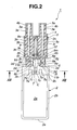
FIG. 2 is a longitudinal sectional view of the medicine sprayer according to the first embodiment of the present invention. -
FIG. 3 is a perspective view of the medicine sprayer according to the first embodiment of the present invention. -
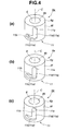
FIG. 4 is a perspective view of a protrusion which forms a guide mechanism provided to the medicine sprayer. -
FIG. 5 is a perspective view of the medicine sprayer according to the first embodiment of the present invention, in which a second divided member is relatively pivoted with respect to a first divided member in a circumferential direction of a central axis. -
FIG. 6 is a perspective view of the medicine sprayer according to the first embodiment of the present invention, in which the second divided member is separated from the first divided member along the axis direction of the central axis. -
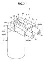
FIG. 7 is a perspective view of the medicine sprayer according to the first embodiment of the present invention, in which the second divided member is inclined by a substantially right angle with respect to the first divided member. -
FIG. 8 is a perspective view of the medicine sprayer according to the first embodiment of the present invention, in which the second divided member is inclined by a substantially right angle with respect to the first divided member, and which is shown from the opposite side ofFIG. 7 . -
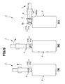
FIG. 9 is a side view of the medicine sprayer according to the first embodiment of the present invention, and showing steps of relative movement of the first divided member and the second divided member. -
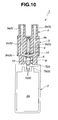
FIG. 10 is a longitudinal sectional view of the medicine sprayer according to the first embodiment of the present invention, and showing a state before a capsule puncture needle pierces a capsule inserted into a capsule insertion hole. -
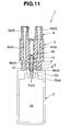
FIG. 11 is a longitudinal sectional view showing the medicine sprayer according to the first embodiment of the present invention, and showing a state in which the capsule puncture needle pierces the capsule. -
FIG. 12 is a longitudinal sectional view showing the medicine sprayer according to the first embodiment of the present invention, and showing a state in which the capsule puncture needle is returned to a needle receiving portion after the capsule puncture needle pierces to the capsule. -
FIG. 13 is a sectional view taken along a line XIII-XIII ofFIG. 2 . -
FIG. 14 is an outer skin section of the medicine sprayer according to the first embodiment of the present invention. -
FIG. 15 is a front view showing an appearance of a medicine sprayer according to a second embodiment of the present invention. -
FIG. 16 is a side view showing an appearance of a medicine sprayer according second embodiment of the present invention. -
FIG. 17 is a side view showing a relative slide state between a first divided member and a second divided member of the medicine sprayer according to the second embodiment of the present invention. -
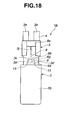
FIG. 18 is a front view showing an appearance of a medicine sprayer according to a third embodiment of the present invention. -
FIG. 19 is a side view showing the appearance of a medicine sprayer according to a third embodiment of the present invention. -
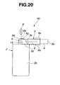
FIG. 20 is a side view showing a relative inclining state of the first divided member and the second divided member of the medicine sprayer according the third embodiment of the present invention. -
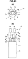
FIGS. 21(a) and 21(b) show a spraying state of a medicine sprayer according to a fourth embodiment of the present invention.FIG. 21(a) is a plan view.FIG. 21(b) is a front view. -
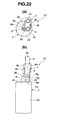
FIGS. 22(a) and 22(b) show a medicine administrating state of the medicine sprayer according to the fourth embodiment of the present invention.FIG. 22(a) is a plan view.FIG. 22(b) is a front view. -
FIGS. 23(a) and 23(b) are views as viewed from a front, and showing the spraying state of the medicine sprayer according to a fifth embodiment of the present invention.FIG. 23(a) is a plan view.FIG. 23(b) is a front view. -
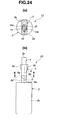
FIGS. 24(a) and 24(b) are views as viewed from a side, and showing the spraying state of a medicine sprayer according to a fifth embodiment of the present invention.FIG. 24(a) is a sectional view taken along a line A-A ofFIG. 24(b). FIG. 24(b) is a side view. -
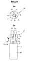
FIGS. 25(a) and (b) are views as viewed from a front, showing a medicine sprayer before the inclination, according to a fifth embodiment of the present invention.FIG. 25(a) is a sectional view taken along a line B-B ofFIG. 25(b). FIG. 25(b) is a front view. -
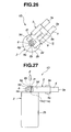
FIG. 26 is a plan view showing the inclined state of the medicine sprayer according to the fifth embodiment of the present invention. -
FIG. 27 is a front view showing the inclined state of the medicine sprayer according to the fifth embodiment of the present invention. - By a first feature of the present invention, the second divided member holding the capsule puncture needle is not separated from the first divided member, and the first divided member is arranged to restrict the advance movement of the capsule puncture needle when the capsule holding portion is exposed to attach or detach the capsule.
Accordingly, it is possible to ensure the sanitary and the safety without touching the capsule puncture needle. - By a second feature of the present invention, the outlet of the capsule puncture needle confronts the outer surface of the side wall of the capsule insertion hole when the first divided member and the second divided member are in the posture in which the capsule insertion hole is exposed. Accordingly, it is possible to exemplify the structure in which the first divided member is arranged to restrict the advance movement of the capsule puncture needle, by the further simple structure.
- By a third feature of the present invention, in a state in which the guide member is guided by the guide groove, the end surface of the protrusion and the bottom surface between the pair of the arm portions are abutted on each other to ensure the sealing characteristic at this portion. In the state in which the guide member is guided by the portion extending in a direction in which the end surface and the bottom surface of the guide groove are abutted on or separated from each other, the end surface and the bottom surface are separated from each other. Accordingly, it is possible to further readily relatively pivot the first divided member and the second divided member.
- By a fourth feature of the present invention, the first divided member and the second divided member are connected with each other to be relatively slid. The outlet of the capsule puncture needle confronts the upper wall of the capsule insertion hole when the first divided member and the second divided member are in the posture in which the capsule insertion hole is exposed. Accordingly, it is possible to exemplify the structure in which the first divided member is arranged to restrict the advance movement of the capsule puncture needle in connection with the relative sliding movement of the first divided member and the second divided member, by the further simple structure.
- By a fifth feature of the present invention, in a state in which the guide member is guided in the guide groove, the end surface of the protrusion and the bottom surface between the pair of the arm portions are abutted on each other to ensure the sealing characteristic at this portion. In the state in which the guide member is guided by the portion extending in a direction in which the end surface of the guide groove and the bottom are deviated from each other, the end surface and the bottom surface are separated from each other. Accordingly, it is possible to further readily relatively slide the first divided member and the second divided member.
- By a sixth feature of the present invention, the first divided member and the second divided member are connected to be relatively inclined. The outlet of the capsule puncture needle confronts the outside of the side wall of the capsule insertion hole when the first divided member and the second divided member are in the inclined posture in which the capsule insertion hole is exposed. Accordingly, it is possible to exemplify the structure in which the first divided member is arranged to restrict the advance movement of the capsule puncture needle in connection with the relative inclination of the first divided member and the second divided member, by the further simple structure.
- By a seventh feature of the present invention, in the stage before the relative inclination of the first divided member and the second divided member, the covering portion is arranged to restrict the advance movement of the capsule puncture needle. Accordingly, it is possible to restrict the advance movement of the capsule puncture needle, and to smoothly perform the relative inclination of the first divided member and the second divided member.
- By an eighth feature, in the posture in which the capsule insertion hole is hid by the second divided member, it is possible to pass the capsule puncture needle through the puncture hole provided to the covering portion, to the capsule insertion hole.
- By a ninth feature, the guide groove includes a portion extending substantially in a direction crossing a direction in which the end surface and the bottom surface are abutted on or separated from each other, so that the first divided member and the second divided member are engaged on each other in a direction in which the first divided member and the second divided member are abutted on or separated from each other. Accordingly, it is possible to suppress the first divided member and the second divided member from being separating from each other.
- By a tenth feature, the protrusion is formed into the cylindrical shape, so that the guide mechanism and the relative pivot mechanism are commonly used. Accordingly, it is possible to simplify the structure. It has the axially symmetrical structure with respect to the central axis of the protrusion. Accordingly, it is possible to stabilize the postures at the relative movement by the guide mechanism and at the relative pivot movement by the relative pivot mechanism, and to obtain further certain operation.
- By an eleventh feature of the present invention, it is possible to suppress the medicine spilled out from the puncture formed in the capsule by the medicine receiving chamber, from reversing to the air pump mechanism. The supplying direction and the discharging direction of the air within the medicine receiving chamber are crossed so as to promote the turbulence and the flow separation of the air flow, and to promote the stir of the air and the medicine. Accordingly, it is possible to discharge the medicine with the air, and to feed the medicine farther. Moreover, it is possible to suppress the medicine from remaining in the medicine sprayer.
- By a twelfth feature of the present invention, it is possible to improve the contact between the capsule holding portion and the outer surface of the capsule, and to improve the sealing of the medicine.
- By a thirteenth feature of the present invention, the swirl flow of the air is formed in the medicine receiving chamber, and it is possible to further promote the stir of the air and the medicine.
- By a fourteenth feature of the present invention, the outer skin section is detachable, and it is possible to further readily keep the outer surface of the medicine sprayer in the clean state.
- Hereinafter, a first embodiment embodying the present invention will be illustrated with reference to the drawings.
- (First Embodiment)
FIG. 1 is a front view showing an appearance of a medicine sprayer according to this embodiment.FIG. 2 is a longitudinal sectional view showing the medicine sprayer.FIG. 3 is a perspective view of the medicine sprayer.FIG. 4 is a perspective view of a protrusion provided to the medicine sprayer.FIGS. 5-8 are perspective views showing the medicine sprayer, and showing steps of relative movements of a first divided member and a second divided member.FIGS. 10-12 are longitudinal sectional views of the medicine sprayer, showing steps after holes are formed in a capsule held in a capsule holding portion, until the medicine within the capsule is discharged.FIG. 13 is a sectional view taken along a line XII-XII ofFIG. 2 .FIG. 14 is a perspective view showing an outer skin section detachably mounted on the medicine discharge port's side. - In this embodiment, the
medicine sprayer 1 is applied to a powder medicine administering apparatus for administering a powder medicine into the nasal cavity. - The
medicine sprayer 1 according to this embodiment includes abody section 2 serving as a first divided member; amovable section 3 serving as a second divided member connected to move relatively (pivot relatively) with respect to thebody section 2; and anouter skin section 4 arranged to cover anouter surface 3b on thedischarge hole 3a's side of themovable section 3. - The
medicine sprayer 1 still stands by striking the bottomedportion 2e of thebody section 2 on a plane such as a table. Hereinafter, an upward direction and a downward direction are defined with reference to this still standing posture (FIG. 1 ). - The
body section 2 is formed by molding an elastomer with the flexibility into a case shape. Thebody section 2 includes anair chamber 2a formed within thebody section 2. Theair chamber 2a is contracted by pressing theouter wall 2b of theair chamber 2a by fingers and so on, so that the air within theair chamber 2a is discharged through air passages 5 (FIG. 10 ). That is, in this embodiment, thebody section 2 serves as an air pump mechanism. - An end portion (upper portion) of the
body section 2 on themovable section 3's side is arigid portion 2c (FIG. 2 ) which does not vary largely by the press of the fingers and so on. Within therigid portion 2c, there are formed acapsule insertion hole 6 serving as a capsule holding portion, and amedicine receiving chamber 7. - The
capsule insertion hole 6 is an inside of acylindrical protrusion 6a protruding on anend surface 2d on themovable section 3's side. Acapsule 8 can be inserted through anopening portion 6b into the capsule insertion hole in a state in which themovable section 3 is inclined to open theopening portion 6b (in a state in which thecapsule insertion hole 6 is exposed :FIGS. 7 ,8 and9(c) ; as described later). As shown inFIG. 2 , a bottomedportion 6c of thecapsule insertion hole 6 is a spherical shape which substantially closely contacts a semiround portion of thecapsule 8. Aninner circumference surface 6d of thecapsule insertion hole 6 is formed so as to guide a cylindrical portion of thecapsule 8 at the insertion. - The medicine receiving chamber 7 (
FIGS. 2 and13 ) is a cylindrical space connected on the bottomedsurface 6c's side of thecapsule insertion hole 6. As shown inFIG. 12 , themedicine receiving chamber 7 receivesmedicine 10 spilled (overflowed) from thecapsule 8 throughpunctures 8b formed in thecapsule 8 by acapsule puncture needle 9, so as to suppress themedicine 10 from entering into theair chamber 2a. - The
medicine receiving chamber 7 is connected with theair chamber 2a through anannular groove portion 7b which is formed on the outer circumference of aside wall 7a, andside holes 7c which penetrate through theside wall 7a, and which is connected with theannular groove portion 7b. The air supplied by the pressure by the compression of theair chamber 2a is introduced though theannular groove portion 7b and the side holes 7c into themedicine receiving chamber 7. In this case, as shown inFIG. 13 , the side holes 7c are opened in a plurality of portions (four portions at 90° in this example) appropriately arranged on aninner circumference surface 7d of themedicine receiving chamber 7 in the circumferential direction. Each of the side holes 7c extends along a tangent line at each opening portion in a substantially winding (vortical) manner. The air introduced from the side holes 7c into themedicine receiving chamber 7 forms rotational flow (vortex flow) in themedicine receiving chamber 7, so as to promote the stirring of themedicine 10 and the air. That is, in this embodiment, themedicine receiving chamber 7 serves as a stirred flow forming section arranged to form the stirred flow of the air supplied by the pressure and themedicine 10. - The movable section 3 (
FIG. 2 ) includes arigid portion 3c having a substantially rectangular cylindrical shape; a pair ofarm portions rigid portion 3c toward thebody section 2, and to sandwich theprotrusion 6a; andinsertion portions arm portions rigid portion 3c, and to be inserted into the nasal cavity. - In the
protrusion 6a and thearm portions FIG. 3 ), there is a guide mechanism 11 (FIG. 4 ) arranged to define the relative movement of thebody section 2 and themovable section 3. In this embodiment, as shown inFIGS 2 ,4 and9 , theguide mechanism 11 includesguide grooves 11a which are formed in the cylindricalouter surface 6f of theprotrusion 6a; andprotrusions arm portion 3d, which have a substantially cylindrical shape, and which serve as guiding members arranged to be inserted into theguide grooves guide grooves cylindrical protrusion 6a. Theprotrusions arm portions outer surface 6f of theprotrusion 6a are inserted, respectively, into thecorresponding guide grooves - As shown in
FIG. 4 , theguide groove 11a has a substantially L-shape, and includes acircumferentially extending portion 11c extending in the circumferential direction; and anaxially extending portion 11d extending in the axial direction of thecylindrical protrusion 6a. - The relative pivot movement about the central axis C of the
body section 2 and themovable section 3 between the posture ofFIG. 3 and the posture ofFIG. 5 is defined by the movement of theprotrusion 11b along thecircumferentially extending portion 11c. The relative movement (approaching and separating movement) in the upward and downward directions of thebody section 2 and themovable section 3 between the posture ofFIG. 5 and the posture ofFIG. 6 (between the posture ofFIG. 9(a) and the posture ofFIG. 9(b) ) is defined by the movement of theprotrusion 11b along theaxially extending portion 11d. - Moreover, as shown in
FIG. 6 (FIG. 9(b) ) andFIG. 7 (FIG. 9(c) ), themovable section 3 is pivoted (inclined) about theprotrusions 11b with respect to thebody section 2 while the force is applied and held in a direction (in the upward direction) in which themovable section 3 is separated from thebody section 2 in a state in which themovable section 3 is separated from the body section 2 (in a state in which theprotrusion 11b is located at a semicylindricalupper end 11e (FIG. 4 ) of theaxially extending portion 11d in this embodiment). Consequently, thebody section 2 and themovable section 3 are bent at substantially right angle. -
FIGS. 2 and3 show a spray enable state in which the medicine sprayer can spray the medicine 10 (FIG. 12 ) (thecapsule 8 and themedicine 10 are omitted). In this state, themovable section 3 covers thecapsule insertion hole 6 formed in thebody section 2. As shown inFIG. 2 , theend surface 2d of thebody section 2 is abutted on the end surfaces 3f of thearm portions bottom surface 3g between the twoarm portions movable section 3 is abutted on theend surface 6g of theprotrusion 6a, and closes theopening portion 6b so as not to leak the medicine 10 (FIG. 12 ) from the boundary between thebody section 2 and themovable section 3 to the outside. Moreover, in this state, aprotrusion 3h formed on thebottom surface 3g is inserted from theopening portion 6b into the upper portion within thecapsule insertion hole 6, so as to hold down the capsule 8 (FIG. 12 ) inserted into thecapsule insertion hole 6, from the opposite side (the upper side) of thebottom surface 6c to squeeze into the bottom side of thecapsule insertion hole 6. Accordingly, it is possible to improve the contact between theouter surface 8a of thecapsule 8 and thebottom surface 6c and the innercircumferential surface 6d of thecapsule insertion hole 6, and to further ensure the sealing of themedicine 10 at these portions. Moreover, a spherical recessedsurface 3i is formed on theprotrusion 3h, and fit on the semiround portion of thecapsule 8. Accordingly, it is possible to further ensure the sealing of themedicine 10 at these portions. - In the
medicine sprayer 1, in this state, thecapsule puncture needle 9 is arranged to be moved through theopening portion 6b into thecapsule insertion hole 6. That is, thecapsule puncture needle 9 is received to extend on the central axis C of thecapsule insertion hole 6 within aneedle receiving portion 3j formed in therigidity portion 3c of themovable section 3. Aslider 9a on which thecapsule puncture needle 9 is fixed is supported on therigid portion 3c to move in the advancing and returning directions along the central axis C. Moreover, in this state, anoutlet 3k of thecapsule puncture needle 9 confronts theopening portion 6b of thecapsule insertion hole 6. Accordingly, as shown inFIG. 11 , theslider 9a supported on therigid portion 3c to be slid in the advancing and returning directions are slid toward the body section 2 (the lower side) by the fingers and so on in a state in which thecapsule 8 is inserted into thecapsule insertion hole 6 as shown inFIG. 10 . Consequently, thecapsule puncture needle 9 fixed on theslider 9a enters from theoutlet 3k into thecapsule insertion hole 6. As shown inFIG. 12 , thepunctures 8b are formed in thecapsule 8. Moreover, in this embodiment, by the movement of thecapsule puncture needle 9, the twopunctures 8b are formed, respectively, at upper and lower portions (the two portions on themedicine receiving chamber 7's side and on the opposite side of the medicine receiving chamber 7). As shown inFIG. 12 , aseal member 12 is mounted at a position corresponding to the position of the end portion of thecapsule puncture needle 9 in a state in which thecapsule puncture needle 9 is received in theneedle receiving portion 3j, so as to suppress the leakage of the air and themedicine 10 around thecapsule puncture needle 9. - On the other hand,
FIG. 6 ,7 ,8 ,9(b), and 9(c) show a spray disable state in which themedicine 10 can not be sprayed. In particular, in a state ofFIGS. 7 ,8 and9(c) , thecapsule insertion hole 6 formed in thebody section 2 is not covered by themovable section 3, and exposed to the outside. As shown inFIG. 8 , it is possible to insert thecapsule 8 through theopening portion 6b into thecapsule insertion hole 6. In this state, thebody section 2 and themovable section 3 are in the bent posture in which thebody section 2 and themovable section 3 are bent at the substantially right angle. Consequently, theoutlet 3k of thecapsule puncture needle 9 from themovable section 3 confronts the cylindricalouter surface 6f of aside wall 6e of theprotrusion 6a of thebody section 2. By thisside wall 6e, it is possible to limit restrict the movement of thecapsule puncture needle 9 to the outside. - As shown in
FIG. 2 , within therigid portion 3c, there are formedair passages capsule insertion hole 6 and thedischarge holes 3a. Theair passage 3m connected with thecapsule insertion hole 6 extends in the upward and downward directions along the central axis C, and serves as a passage for the advancing and the returning movement of thecapsule puncture needle 9. An opening portion of theair passage 3m on the recessedsurface 3i is theoutlet 3k of thecapsule puncture needle 9. Theair passages air passage 3m. Each of theair passages air passage 3m (in a substantially horizontal direction in the still standing state). Each of theair passages air passage 3n which is farther from the central axis C, toward one of theinsertion portions air passages needle receiving portion 3j is disposed between theair passages air passages needle receiving portion 3j and the twoair passages - Hereinafter, operation of spraying the medicine of the
medicine sprayer 1 having the above-described structure will be illustrated. First, in the state ofFIGS. 7 ,8 and9(c) , thecapsule 8 is inserted into thecapsule insertion hole 6 which is not covered by themovable section 3, and which is exposed to the outside. Subsequently, themovable section 3 is raised up as shown inFIGS. 6 and9(b) . Then, themovable section 3 is moved in the downward direction to become the state shown inFIGS. 5 and9(a) . Themovable section 3 is pivoted in the circumferential direction to become the state shown inFIGS. 10 and3 to be the spray enable state. During this period, in theguide mechanism 11, the protrudingportions 11 serving as the guide member are moved within theguide grooves 11a in order ofFIGS. 4 (c) -> (b) -> (a) . In this case, in the movement fromFIG. 4(b) to FIG. 4(a) , it is possible to understand that thecircumferentially extending portions 11c of theguide grooves 11a serve as a lock mechanism arranged to lock thebody section 2 and themovable section 3 in a direction along the central axis C. - Next, the
slider 9a of thebody section 2 is slid in the downward direction from the state shown inFIG. 10 to the state shown inFIG. 11 so as to form, by thecapsule puncture needle 9, the punctures (through holes) 8b and 8b located at the upper and lower portions of thecapsule 8. Theslider 9a is slid in the upward direction to the state shown inFIG. 12 to return thecapsule puncture needle 9 to receivingportion 3j. - In this state of
FIG. 12 , theouter wall 2b of theair chamber 2a is pressed by the fingers and so on, and the air within theair chamber 2a is discharged from theair passage 5. In this case, themedicine 10 within thecapsule 8 and themedicine receiving chamber 7 is discharged with the air supplied by the pressure by the constriction of theair chamber 2a. The air passes through theannular groove portion 7b, the side holes 7c, themedicine receiving chamber 7, thepuncture 8b, the inside of thecapsule 8, thepuncture 8b, theair passage 3m, and theair passages 3n which serve as theair passage 5, and is discharged from thedischarge hole 3a. In this case, the stirred flow (swirl flow) is formed in themedicine receiving chamber 7, and the air and themedicine 10 are effectively mixed. Accordingly, themedicine 10 can surely reaches the bottom of the nasal cavity, and it is possible to suppress themedicine 10 from remaining in themedicine sprayer 1. - The
medicine sprayer 1 according to this embodiment includes theouter skin section 4 which is detachable, and which is closely attached at an end portion of themedicine sprayer 1 which are formed with thedischarge holes 3a. As shown inFIG. 14 , thisouter skin section 4 includes amain portion 4a covering therigid portion 3c of themovable section 3 from the end portion; andcylindrical portions 4b protruding from themain portion 4a, and covering theinsertion portions 3e. A cutaway portion 4c is formed in themain portion 4a, and arranged to avoid the interference with the movement space of theslider 9a. Each of thecylindrical portions 4b includes a throughhole 4d formed at an end portion of thatcylindrical portion 4b, and connected with one of thedischarge holes 3a. Consequently, it is possible to readily keep themedicine sprayer 1 clean by changing theouter skin section 4, without cleaning the surface of themedicine sprayer 1. - In the above mentioned embodiment, the
body section 2 is formed with thecapsule insertion hole 6 arranged to hold thecapsule 8. Themovable section 3 includes thecapsule puncture needle 9 arranged to be moved into or out of thecapsule insertion hole 6. Thebody section 2 and themovable section 3 are connected with each other to be relatively moved at least between the posture in which at thecapsule insertion hole 6 is exposed and the posture in which the capsule insertion hole is hid by themovable section 3. Thebody section 2 is arranged to restricts the advancing movement of thecapsule puncture needle 9 in a state in which thebody section 2 and themovable section 3 are in the posture in which thecapsule insertion hole 6 is exposed. Accordingly, it is possible to suppress thecapsule puncture needle 9 from exposing, and to further ensure the sanitary and the safety of thecapsule puncture needle 9. - In this embodiment, the
body section 2 and themovable section 3 are connected with each other to be relatively pivoted at least between the posture in which thecapsule insertion hole 6 is exposed and the posture in which thecapsule insertion hole 6 is hid. In the state in which thebody section 2 and themovable section 3 are in the posture in which thecapsule insertion hole 6 is hid, theoutlet 3k of thecapsule puncture needle 9 from themovable section 3 confronts theopening portion 6b of thecapsule insertion hole 6, and thecapsule puncture needle 9 can move into or out of thecapsule insertion hole 6 from theopening portion 6b. In the state in which thebody section 2 and themovable section 3 are in the posture in which thecapsule insertion hole 6 is exposed, theoutlet 3k confronts the outside of theside wall 6e of thecapsule insertion hole 6, and theside wall 6e is arranged to restricts the advancing movement of thecapsule puncture needle 9. Accordingly, it is possible to exemplify the structure in which thebody section 2 restricts the exposure of thecapsule puncture needle 9 from themovable section 3, by a relatively simple structure. - In this example, the
capsule insertion hole 6 is the cylindrical hole of thecylindrical protrusion 6a formed in thebody section 2. The pair of thearm portions 3d are formed in themovable section 3, and arranged to sandwich theprotrusion 6a. Theguide grooves 11a are formed in one of theprotrusion 6a and thearm portions 3d. The protrudingportions 11b are formed in the other of theprotrusion 6a and thearm portions 3d, and arranged to serve as the guide member arranged to guide into theguide groove 11a. In the state in which thebody section 2 and themovable section 3 are in the posture in which thecapsule insertion hole 6 is hid, theend surface 6g of theprotrusion 6a and thebottom surface 3g between the pair of thearm portions bottom surface 3g is arranged to close theopening portion 6b of thecapsule insertion hole 6. Each of theguide groove 11a includes theaxially extending portion 11d arranged to extend in a direction in which theend surface 6g and thebottom surface 3g are abutted on and separated from each other. When thebody section 2 and themovable section 3 are changed from the posture in which thecapsule insertion hole 6 is hid to the posture thecapsule insertion hole 6 is exposed, theend surface 6g and thebottom surface 3g are separated from each other. Accordingly, it is possible to ensure the sealing characteristic of theopening portion 6b of thecapsule insertion hole 6, and to exemplify the mechanism in which thebody section 2 and themovable section 3 are separated from each other to be readily relatively pivoted from each other, by the relatively simple structure. - (Second Embodiment)
FIGS. 15-16 show a second embodiment of the present invention. The structure of the second embodiment is substantially identical to the structure of the first embodiment in most aspects as shown by the use of the same reference numerals. The repeated illustrations are omitted.FIG. 15 is a front view showing an appearance of a medicine sprayer according to this embodiment.FIG. 16 is a side view showing an appearance of the medicine sprayer according to the this embodiment.FIG. 17 is a side view showing a relative sliding state of the first divided member and the second divided member. In this embodiment, the medicine sprayer is also a powder medicine administrating apparatus for administrating the powder medicine into the nasal cavity. - The
medicine sprayer 1A according to this embodiment has a structure substantially identical to the structure of the first embodiment, as shown inFIG. 15 . Themedicine sprayer 1A includes abody section 2 serving as the first divided member, and amovable section 3 serving as the second divided member connected to be relatively moved (relatively slid) with respect to thebody section 2. - The
capsule insertion hole 6 is formed in thebody section 2, and arranged to serve as a capsule holding portion. Thebody section 2 and themovable section 3 are connected to be relatively slid at least between the posture in which thecapsule insertion hole 6 is exposed as shown inFIG. 17 , and the posture in which thecapsule insertion hole 6 is hid as shown inFIG. 16 . - In the state in which the
body section 2 and themovable section 3 are in the posture in which thecapsule insertion hole 6 is hid, theoutlet 3k (cf.FIG. 2 ) of thecapsule puncture needle 9 from themovable section 3 confronts theopening portion 6b of thecapsule insertion hole 6, and thecapsule puncture needle 9 can be moved into or out of thecapsule insertion hole 6 from theopening portion 6b (cf.FIG. 2 ). - In the state in which the
body section 2 and themovable section 3 are in the posture in which thecapsule insertion hole 6 is exposed, theoutlet 3k confronts the upper wall of thecapsule insertion hole 6, that is, theend surface 6g of theprotrusion 6a, and theend surface 6g is arranged to restricts the advancing movement of thecapsule puncture needle 9. Thecapsule insertion hole 6 is formed in thecylindrical protrusion 6a protruding from thebody section 2, like the first embodiment. Thecapsule insertion hole 6 is the cylindrical hole of theprotrusion 6a. - The pair of the
arm portions 3d are provided to themovable section 3, and arranged to sandwich theprotrusion 6a. Theguide grooves 11a are formed in right and left side surfaces (in the rightward and leftward directions ofFIG. 15 ) of theprotrusion 6a for the relatively sliding movement, and theguide grooves 11a extend in the forward and rearward directions (in the front and back directions ofFIG. 15 ), as shown inFIG. 16 . The protrudingportions 11b are provided to thearm portion 3d, and arranged to be guided by theguide grooves 11a. The protrudingportions 11b are slid within theguide grooves 11a, and thebody section 2 and themovable section 3 can be relatively slid in the forward and rearward directions. In this case, theguide grooves 11a may be formed in thearm portion 3d, and the protrudingportions 11b may be provided in theprotrusion 6a. - In the state in which the
body section 2 and themovable section 3 are in the posture in which thecapsule insertion hole 6 is hid as shown inFIG. 16 , theend surface 6g of theprotrusion 6a and thebottom surface 3g (cf.FIG. 2 ) between the pair of thearm portions 3d are abutted on each other, and thebottom surface 3g closes theopening portion 6b of thecapsule insertion hole 6. Theprotrusion 6a includes anextension portion 6h extending in a direction in which theopening portion 6b of thecapsule insertion hole 6 is deviated from theoutlet 3k of thecapsule puncture needle 9. When thebody section 2 and themovable section 3 are brought from the posture in which thecapsule insertion hole 6 is hid (cf.FIG. 16 ) to the posture in which thecapsule insertion hole 6 is exposed (cf.
FIG. 17 ), theopening portion 6b andoutlet 3k are separated from each other. - In the medicine spraying operation of the
medicine sprayer 1A, thecapsule 8 is fit into thecapsule insertion hole 6 which is exposed to the outside, and which is not covered by themovable section 3, in the state ofFIG. 17 . Themovable section 3 is slid along theguide groove 11a as shown inFIG. 16 . Thebottom surface 3g of thearm portions 3d closes theopening portion 6b of thecapsule insertion hole 6. In this state, themedicine sprayer 1A becomes the spraying enable state. Subsequently, theslider 9a of thebody section 2 is slid in the downward direction, and thecapsule puncture needle 9 forms the punctures at the upper portion and the lower portion of thecapsule 8, like the first embodiment. Then, theslider 9a is slid in the upward direction to the original state (cf.FIG. 15 ), so that thecapsule puncture needle 9 is returned to theneedle receiving portion 3j. - In the
medicine sprayer 1A according to this embodiment, thebody section 2 and themovable section 3 are connected to be relatively slid. When thebody section 2 and themovable section 3 are in the posture in which thecapsule insertion hole 6 is exposed, theoutlet 3k of thecapsule puncture needle 9 confronts theend surface 6g of thecapsule insertion hole 6. Accordingly, it is possible to exemplify the structure in which thebody section 2 is arranged to restrict the advancing movement of thecapsule puncture needle 9 in connection with the sliding movement of thebody section 2 and themovable section 3, by the further simple structure. - Moreover, in the state in which the protruding
portions 11b are guided by theguide grooves 11a, theend surface 6g of theprotrusion 6a and thebottom surface 3g between the pair of thearm portions 3d are abutted on each other. Accordingly, it is possible to ensure the sealing characteristic at this portion. In the state in which theprotrusions 11b are guided within theguide grooves 11a in theextension portion 6h extending in the direction in which theend surface 6g of and thebottom surface 3g are deviated, theend surface 6g and thebottom surface 3g are separated from each other. Accordingly, it is possible to readily slide thebody section 2 and themovable section 3. - (Third Embodiment)
FIGS. 18-20 show a third embodiment of the present invention. The structure of the third embodiment is substantially identical to the structure of the first embodiment in most aspects as shown by the use of the same reference numerals. The repeated illustrations are omitted.FIG. 18 is a front view showing an appearance of a medicine sprayer according to this embodiment.FIG. 19 is a side view showing the appearance of the medicine sprayer according to this embodiment.FIG. 20 is a side view showing a relatively inclining state of the first divided member and the second divided member. In this embodiment, the medicine sprayer is also a powder medicine administrating apparatus for administrating the powder medicine into the nasal cavity. - The
medicine sprayer 1B according to this embodiment has a structure substantially identical to the structure of the first embodiment, as shown inFIG. 18 . Themedicine sprayer 1B includes abody section 2 serving as the first divided member, and amovable section 3 serving as the second divided member connected to be relatively moved (relatively inclined) with respect to thebody section 2. - The
capsule insertion hole 6 is formed in thebody section 2, and arranged to serve as a capsule holding portion. Thebody section 2 and themovable section 3 are connected to be relatively inclined at least between the posture in which thecapsule insertion hole 6 is exposed as shown inFIG. 20 , and the posture in which thecapsule insertion hole 6 is hid as shown inFIG. 19 . - In the state in which the
body section 2 and themovable section 3 are in the posture in which thecapsule insertion hole 6 is hid, theoutlet 3k (cf.FIG. 2 ) of thecapsule puncture needle 9 from themovable section 3 confronts theopening portion 6b of thecapsule insertion hole 6, and thecapsule puncture needle 9 can be moved into or out of thecapsule insertion hole 6 from theopening portion 6b (cf.FIG. 2 ). - In the state in which the
body section 2 and themovable section 3 are in the posture in which thecapsule insertion hole 6 is exposed, theoutlet 3k confronts the outside of theside wall 6e of thecapsule insertion hole 6, and theside wall 6e is arranged to restrict the advancing movement of thecapsule puncture needle 9. Theprotrusion 6a is formed into a substantially semiround shape as viewed from the side, as shown inFIG. 19 . Theprotrusion 6a has theside wall 6e located on the lateral side of the outer circumferential surface. - A pair of
arm portions 3d are provided to themovable section 3 as shown inFIG. 18 , and arranged to sandwich theprotrusion 6a. Thesearm portions 3d can be pivoted bypin portions 13 protruding from a center portion of thesemiround protrusion 6a. Themovable section 3 can be inclined about thepin portions 13 as shown inFIG. 20 . - In the medicine spraying operation of the
medicine sprayer 1B, themovable section 3 is inclined about thepin portions 13 as shown inFIG. 20 , so that thecapsule insertion hole 6 covered by themovable section 3 is exposed to the outside. Thecapsule 8 is fit into thecapsule insertion hole 6, and themovable section 3 is pivoted as shown inFIG. 19 , and raised up in the initial position. Thebottom surface 3g of thearm portions 3d closes theopening portion 6b of thecapsule insertion hole 6. - In this state, the
medicine sprayer 1A becomes the spraying enable state. Subsequently, theslider 9a of thebody section 2 is slid in the downward direction, and thecapsule puncture needle 9 forms the punctures at the upper portion and the lower portion of thecapsule 8, like the first embodiment. Then, theslider 9a is slid in the upward direction to the original state (cf.FIG. 18 ), so that thecapsule puncture needle 9 is returned to theneedle receiving portion 3j. - In the
medicine sprayer 1B according to this embodiment, thebody section 2 and themovable section 3 are connected to be relatively inclined. When thebody section 2 and themovable section 3 are in the posture in which thecapsule insertion hole 6 is exposed, theoutlet 3k of thecapsule puncture needle 9 confronts theside wall 6e of thecapsule insertion hole 6. Accordingly, it is possible to exemplify the structure in which thebody section 2 is arranged to restrict the advancing movement of thecapsule puncture needle 9 in connection with the relatively inclining movement of thebody section 2 and themovable section 3, by the further simple structure. - (Fourth Embodiment)
FIGS. 21 and22 show a fourth embodiment of the present invention. The structure of the fourth embodiment is substantially identical to the structures of the first and second embodiments in most aspects as shown by the use of the same reference numerals. The repeated illustrations are omitted.FIG. 21 shows a spraying state of the medicine sprayer.FIG. 21(a) is a plan view.FIG. 21(b) is a front view.FIG. 22 shows a medicine administrating state of the medicine sprayer.FIG. 22(a) is a plan view.FIG. 22(b) is a front view. In this embodiment, the medicine sprayer is also a powder medicine administrating apparatus for administrating the powder medicine into the nasal cavity. - The
medicine sprayer 1C according to this embodiment has a structure substantially identical to the structure of the second embodiment, as shown inFIG. 21 . The medicine sprayer 1C includes abody section 2 serving as the first divided member, and amovable section 3 serving as the second divided member connected to be relatively moved (relatively slid) with respect to thebody section 2. - The
capsule insertion hole 6 is formed in thebody section 2, and arranged to serve as a capsule holding portion. Thebody section 2 and themovable section 3 is connected to be relatively slid at least between the posture in which thecapsule insertion hole 6 is exposed as shown inFIG. 22 , and the posture in which thecapsule insertion hole 6 is hid as shown inFIG. 21 . - In the state in which the
body section 2 and themovable section 3 are in the posture in which thecapsule insertion hole 6 is hid, theoutlet 3k (cf.FIG. 2 ) of thecapsule puncture needle 9 from themovable section 3 confronts theopening portion 6b of thecapsule insertion hole 6, and thecapsule puncture needle 9 can be moved into or out of thecapsule insertion hole 6 from theopening portion 6b (cf.FIG. 2 ). - In the state in which the
body section 2 and themovable section 3 are in the posture in which thecapsule insertion hole 6 is exposed, theoutlet 3k confronts theend surface 6g of thecapsule insertion hole 6, and theend surface 6g is arranged to restrict the advancing movement of thecapsule puncture needle 9. Thecapsule insertion hole 6 is formed in thecylindrical protrusion 6a protruding from thebody section 2, like the first embodiment. Thecapsule insertion hole 6 is the cylindrical hole of theprotrusion 6a. - The pair of the
arm portions 3d are provided to themovable section 3, and arranged to sandwich theprotrusion 6a. One of thearm portions 3d (on the right side ofFIG. 21 ) is mounted to thebody section 2 to be pivoted by arotation center shaft 14. Thebody section 2 and themovable section 3 can be relatively slid about therotation center shaft 14. - In the state in which the
body section 2 and themovable section 3 is in the posture in which thecapsule insertion hole 6 is hid as shown inFIG. 21 , theend surface 6g of theprotrusion 6a and thebottom surface 3g (cf.FIG. 2 ) between the pair of thearm portions 3d are abutted on each other, and thebottom surface 3g closes theopening portion 6b of thecapsule insertion hole 6. Theprotrusion 6a includes anextension portion 6h extending in a direction in which theopening portion 6b of thecapsule insertion hole 6 is deviated from theoutlet 3k of thecapsule puncture needle 9. Theextension portion 6h is formed into an arc shape whose a center is therotation center shaft 14, in the plan view. The pair of thearm portions 3d are guided and slid on the both sides of theextension portion 6h. When thebody section 2 and themovable section 3 are brought from the posture in which thecapsule insertion hole 6 is hid (cf.FIG. 21 ) to the posture in which thecapsule insertion hole 6 is exposed (cf.FIG. 22 ), theopening portion 6b and theoutlet 3k are separated from each other. - In the medicine spraying operation of the
medicine sprayer 1C, thecapsule 8 is fit into thecapsule insertion hole 6 which is exposed to the outside, and which is not covered by themovable section 3, in the state ofFIG. 22 . Themovable section 3 is slid along theextension portion 6h of theprotrusion 6a as shown inFIG. 21 , so that thebottom surface 3g of thearm portions 3d closes theopening portion 6b of thecapsule insertion hole 6. In this state, themedicine sprayer 1C becomes the spraying enable state. Subsequently, theslider 9a of thebody section 2 is slid in the downward direction, and thecapsule puncture needle 9 forms the punctures at the upper portion and the lower portion of thecapsule 8, like the first embodiment. Then, theslider 9a is slid in the upward direction to the original state (cf.FIG. 21 ), so that thecapsule puncture needle 9 is returned to theneedle receiving portion 3j. - In the
medicine sprayer 1C according to this embodiment, thebody section 2 and themovable section 3 are connected to be relatively slid. When thebody section 2 and themovable section 3 are in the posture in which thecapsule insertion hole 6 is exposed, theoutlet 3k of thecapsule puncture needle 9 confronts theend surface 6g of thecapsule insertion hole 6. Accordingly, it is possible to exemplify the structure in which thebody section 2 is arranged to restrict the advancing movement of thecapsule puncture needle 9 in connection with the relatively sliding movement of thebody section 2 and themovable section 3, by the further simple structure. - Moreover, in the state in which the protruding
portions 11b are guided by theguide grooves 11a, theend surface 6g of theprotrusion 6a and thebottom surface 3g between the pair of thearm portions 3d are abutted on each other. Accordingly, it is possible to ensure the sealing characteristic at this portion. In the state in which theprotrusions 11b are guided within theguide grooves 11a in theextension portion 6h extending in the direction in which theend surface 6g of and thebottom surface 3g are deviated, theend surface 6g and thebottom surface 3g are separated from each other. Accordingly, it is possible to readily slide thebody section 2 and themovable section 3. - (Fifth Embodiment)
FIGS. 23-27 show a fifth embodiment of the present invention. The structure of the fifth embodiment is substantially identical to the structure of the first embodiment in most aspects as shown by the use of the same reference numerals. The repeated illustrations are omitted.FIG. 23 is a front view showing a spraying state of the medicine sprayer.FIG. 23(a) is a plan view.FIG. 23(b) is a front view.FIG. 24 is a side view showing the spraying state of the medicine sprayer.
FIG. 24(a) is a sectional view taken along a line A-A ofFIG. 24(b). FIG. 24(b) is a side view.FIG. 25 is a front view showing the medicine sprayer before the inclination.FIG. 25(a) is a sectional view taken along a line B-B ofFIG. 25(b). FIG. 25(b) is a front view.FIG. 26 is a plan view showing the inclining state of the medicine sprayer.FIG. 27 is a front view showing the inclining state of the medicine sprayer. In this embodiment, the medicine sprayer is also a powder medicine administrating apparatus for administrating the powder medicine into the nasal cavity. - The
medicine sprayer 1D according to this embodiment has a structure substantially identical to the structure of the first embodiment, as shown inFIG. 23 .
Themedicine sprayer 1D includes abody section 2 serving as the first divided member, and amovable section 3 serving as the second divided member connected to be relatively moved (relatively slid) with respect to thebody section 2. - The
capsule insertion hole 6 is formed in thebody section 2, and arranged to serve as a capsule holding portion. Thebody section 2 and themovable section 3 are connected to be relatively inclined at least between the posture in which thecapsule insertion hole 6 is exposed as shown inFIGS. 26 and 27 , and the posture in which thecapsule insertion hole 6 is hid as shown inFIGS. 23 and24 . In this embodiment, thebody section 2 and themovable section 3 have a state before the inclination which is between the posture in which thecapsule insertion hole 6 is exposed and the posture in which thecapsule insertion hole 6 is hid, and in which themovable section 3 is rotated with respect to thebody section 2 a predetermined angle (substantially 45° in this embodiment). - In the state in which the
body section 2 and themovable section 3 are in the posture in which thecapsule insertion hole 6 is hid, theoutlet 3k (cf.FIG. 2 ) of thecapsule puncture needle 9 from themovable section 3 confronts theopening portion 6b of thecapsule insertion hole 6 , and thecapsule puncture needle 9 can be moved into or out of thecapsule insertion hole 6 from theopening portion 6b (cf.FIG. 2 ). - As shown in
FIGS. 24 and25 , themovable section 3 includes a coveringportion 15 arranged to cover thecapsule insertion hole 6, and to move at the stage before the relative inclination of thebody section 2 and themovable section 3. The coveringportion 15 is arranged to restrict the advancing movement of thecapsule puncture needle 9 at the stage before the relative inclination of thebody section 2 and themovable section 3. Thecapsule insertion hole 6 is formed in thecylindrical protrusion 6a protruding from thebody section 2, like the first embodiment. Thecapsule insertion hole 6 is the cylindrical hole of theprotrusion 6a. - The covering
portion 15 is formed into a substantially circular plate whose a part of an outer circumference portion is cut away. The coveringportion 15 is received within a lower end portion of themovable section 3 in a state in which themedicine sprayer 1D still stands, that is, within a receivingchamber 3p formed below thecapsule puncture needle 9, so as to be moved in a direction perpendicular to the central axis C. - The covering
portion 15 includes apuncture hole 15a through which thecapsule puncture needle 9 passes to thecapsule insertion hole 6, in the state in which thecapsule insertion hole 6 is hid by themovable section 3, that is, in the spraying state of the medicine sprayer shown inFIGS. 23 and24 . The coveringportion 15 is arranged to move within the receivingchamber 3p, and to rotate as a unit with themovable section 3 about the central axis C of themovable section 3 by an engagement portion (not shown). - An
arc restriction wall 2f protrudes from thebody section 2, and is inserted into the receivingchamber 3p. Therestriction wall 2f has a predetermined cam function, and is arranged to be mounted in thecutaway portion 15b of the coveringportion 15. The inner chamber shape of the receivingchamber 3p is an oval shape extending in the movable direction of the coveringportion 15. Between the receivingchamber 3p and the coveringportion 15, there is provided aspring 16 arranged to press and urge the coveringportion 15 in one direction, that is, in a direction in which thepuncture hole 15a is deviated from the advancing movement of thecapsule puncture needle 9. - The
restriction wall 2f forcibly moves the coveringportion 15 against the urging force of thespring 16 in the other direction (in the downward direction in the figure) when themovable section 3 is at the rotation position in the initial state (spraying state) so that thepuncture hole 15a corresponds to the direction of the advancing movement of thecapsule puncture needle 9. In this state, it is possible to perform the advancing movement of thecapsule puncture needle 9. Moreover, therestriction wall 2f serves as a guide when thecapsule 8 is inserted into thecapsule insertion hole 6. - Next, when the
movable section 3 is rotated to the stage before the inclination as shown inFIG. 25 , the correction force of the coveringportion 15 by therestriction wall 2f is released, the coveringportion 15 is pushed in the one direction by thespring 16, and thepuncture hole 15a is deviated from the direction of the advancing movement of thecapsule puncture needle 9. In this state, thecapsule puncture needle 9 is interrupted by the coveringportion 15 to prevent the advancing movement. In this state in which the advancing movement of thecapsule puncture needle 9 is prevented, themovable section 3 is inclined as shown inFIGS. 26 and 27 . In this case, the coveringportion 15 is inclined with themovable section 3. - The
guide grooves 11a are formed in an outer cylindrical surface of theprotrusion 6a, like the first embodiment (cf.FIG. 4 ). Protrudingportions 11b are formed in thearm portion 3d, and arranged to be inserted into theguide grooves guide groove 11a is formed in a (axially) symmetrical manner with respect to the central axis of thecylindrical protrusion 6a. The protrudingportions 11b protrude on the abutment surface between thearm portions protrusion 6a, and are inserted, respectively, into thecorresponding guide grooves 11a. - Each of the
guide grooves 11a includes acircumferentially extending portion 11c extending in the circumferential direction partially as shown inFIGS. 25 and27 , and anaxially extending portion 11d extending in the axial direction of thecylindrical protrusion 6a. Each of theguide grooves 11a is formed into a substantially L-shape. - The relative pivot movement of the
body section 2 and themovable section 3 about the central axis C between the posture ofFIG. 23 and the posture ofFIG. 25 is defined by the movement of the protrudingportion 11b along thecircumferentially extending portion 11c. The relative inclination of thebody section 2 and themovable section 3 between the posture ofFIG. 25 and the posture ofFIG. 27 is defined by the movement of the protrudingportion 11b along theaxially extending portion 11d. In this case, themovable section 3 is inclined about the protrudingportion 11b with respect to thebody section 2, thebody section 2 and themovable section 3 can be bent at a substantially right angle. In this case, theguide groove 11a may be formed in thearm portion 3d, and the protrudingportion 11b may be formed in theprotrusion 6a. - In the medicine spraying operation of the
medicine sprayer 1D, thecapsule 8 is fit into thecapsule insertion hole 6 which is exposed to the outside, and which is not covered by themovable section 3, in the state ofFIGS. 26 and 27 . Themovable section 3 in the inclined state is raised as shown inFIG. 25 . Then, themovable section 3 is rotated about the central axis C to return to the initial state as shown inFIGS. 23 and24 . In this state, thebottom surface 3g of thearm portion 3d closes theopening portion 6b of thecapsule insertion hole 6 to become the spray enable state. Subsequently, theslider 9a of thebody section 2 is slid in the downward direction, and thecapsule puncture needle 9 forms the holes at the upper portion and the lower portion of thecapsule 8, like the first embodiment. Then, theslider 9a is slid in the upward direction to the original state (cf.FIG. 23 ), so that thecapsule puncture needle 9 is returned to theneedle receiving portion 3j. - Accordingly, in the
medicine sprayer 1D according to this embodiment, the coveringportion 15 restricts the advancing movement of thecapsule puncture needle 9 at the stage (cf.FIG. 25 ) before the relative inclination of thebody section 2 and themovable section 3. Accordingly, it is possible to suppress thecapsule puncture needle 9 from exposing from themovable section 3 by the coveringportion 15, except for the spraying state. Moreover, the coveringportion 15 restricts the advancing movement of thecapsule puncture needle 9 by the coveringportion 15, and accordingly it is possible to smoothly incline themovable section 3 with respect to thebody section 2. - The covering
portion 15 allows thecapsule puncture needle 9 to pass through thepuncture holes 15a provided to the coveringportion 15 in the posture in which thecapsule insertion hole 6 is hid by themovable section 3, that is, in the spray state shown inFIGS. 23 and24 . Accordingly, it is possible to form the holes in thecapsule 8 by thecapsule puncture needle 9 at the spraying of the medicine in case of providing coveringportion 15, like the above-mentioned embodiments. - The preferred embodiments of the present invention was illustrated above. However, the present invention is not limited to the above-mentioned embodiments. The present invention can varied in the various manner.
- The present invention is applicable to a medicine sprayer arranged to discharge the powder medicine into the nasal cavity, the oral cavity and so on by the hand.
-
- 1, 1A, 1B, 1C, 1D medicine sprayer
- 2 body section (first divided member, air pump mechanism)
- 2a air chamber
- 3 movable section (second divided member)
- 3d arm portion
- 3g bottom surface
- 3k outlet
- 5 air passage
- 6 capsule insertion hole (capsule holding portion)
- 6b opening portion
- 6e side wall
- 6f cylindrical outer surface (outside)
- 6g end surface (upper side wall)
- 8 capsule
- 9 capsule puncture needle
- 10 medicine
- 11 guide mechanism
- 11a guide groove
- 11b protrusion
- 11d axially extending portion
- 15 covering portion
- 15a puncture hole
Claims (14)
- A medicine sprayer comprising:an air pump mechanism arranged to supply an air by a pressure;a capsule puncture needle arranged to form a hole in a capsule;an air passage arranged to discharge a medicine received within the capsule to the outside, by the air supplied by the air pump mechanism;a first divided member formed with a capsule holding portion holding the capsule;a second divided member including the capsule puncture needle arranged to be moved into or out of the capsule holding portion;the first divided member and the second divided member being connected to be relatively moved at least between a posture in which the capsule holding portion is exposed, and a posture in which the capsule holding portion is hid by the second divided member,the first divided member being arranged to restrict the advancing movement of the capsule puncture needle when the first divided member and the second divided member are in the posture in which the capsule holding portion is exposed.
- The medicine sprayer as claimed in Claim 1, wherein the first divided member includes a capsule insertion hole serving as the capsule holding portion; the first divided member and the second divided member are connected to be relatively pivoted at least between a posture in which the capsule insertion hole is exposed, and a posture in which the capsule insertion hole is hid; an outlet of the capsule puncture needle from the second divided member confronts an opening portion of the capsule insertion hole when the first divided member and the second divided member are in the posture in which the capsule insertion hole is hid so that the capsule puncture needle is arranged to be moved from the opening portion into the capsule insertion hole; and the outlet confronts an outer side of a side wall when the first divided member and the second divided member are in the posture in which the capsule insertion hole is exposed so that the side wall restricts the advancing movement of the capsule puncture needle.
- The medicine sprayer as claimed in Claim 2, wherein the first divided member includes a cylindrical protrusion; the capsule insertion hole is a cylindrical hole of the protrusion; the second divided member includes a pair of arm portions arranged to sandwich the protrusion; one of the protrusion and the arm portions includes a guide groove; the other of the protrusion and the arm portions includes a guide groove arranged to be guided in the guide groove; an end surface of the protrusion and a bottom surface between the pair of the arm portions are abutted on each other when the first divided member and the second divided member are in the posture in which the capsule insertion hole is hid so that the bottom surface closes the opening portion of the capsule insertion hole; the guide groove includes a portion extending in a direction in which the end surface and the bottom surface is abutted on or separated from each other so that the end surface and the bottom surface are separated from each other when the first divided member and the second divided member are changed from the posture in which the capsule insertion hole is hid to the posture in which the capsule insertion hole is exposed.
- The medicine sprayer as claimed in Claim 1 or 3, wherein the first divided member includes a capsule insertion hole serving as the capsule holding portion; the first divided member and the second divided member are connected to be relatively slid at least between a posture in which the capsule insertion hole is exposed, and a posture in which the capsule insertion hole is hid; an outlet of the capsule puncture needle from the second divided member confronts an opening portion of the capsule insertion hole when the first divided member and the second divided member are in the posture in which the capsule insertion hole is hid so that the capsule puncture needle is moved from the opening portion into the capsule insertion hole; and the outlet confronts an upper wall of the capsule insertion hole when the first divided member and the second divided member are in the posture in which the capsule insertion hole is exposed so that the upper wall restricts the advance movement of the capsule puncture needle.
- The medicine sprayer as claimed in Claim 4, wherein the first divided member includes a cylindrical protrusion; the capsule insertion hole is a cylindrical hole of the protrusion; the second divided member includes a pair of arm portions arranged to sandwich the protrusion; one of protrusion and the arm portion includes a guide groove; the other of the protrusion and the arm portions includes a guide portion arranged to be guided in the guide groove; an end surface of the protrusion and the bottom surface between the pair of the arm portions are abutted on each other when the first divided member and the second divided member are in the posture in which the capsule insertion hole is hid so that the bottom surface closes an opening portion of the capsule insertion hole; the protrusion includes a portion extending in a direction in which the opening portion of the capsule insertion hole and the outlet of the capsule puncture needle are deviated from each other so that the opening portion and the outlet are separated form each other when the first divided member and the second divided member are changed from the posture in which the capsule insertion hole is hid to the posture in which the capsule insertion hole is exposed.
- The medicine sprayer as claimed in Claim 1, wherein the first divided member include a capsule insertion hole serving as the capsule holding portion; the first divided member and the second divided member are connected to be relatively inclined at least between a posture in which the capsule insertion hole is exposed, and a posture in which the capsule insertion hole is hid; an outlet of the capsule puncture needle from the second divided member confronts an opening portion of the capsule insertion hole when the first divided member and the second divided member are in the posture in which the capsule insertion hole is hid so that the capsule puncture needle is arranged to be moved from the opening portion into the capsule insertion hole; and the outlet confronts an outer side of a side wall of the capsule insertion hole when the first divided member and the second divided member are in the posture in which the capsule insertion hole is exposed so that the side wall restricts the advance movement of the capsule puncture needle.
- The medicine sprayer as claimed in Claim 1, wherein the first divided member includes a capsule insertion hole serving as the capsule holding portion; the first divided member and the second divided member are connected to be relatively inclined at least between a posture in which the capsule insertion hole is exposed, and a posture in which the capsule insertion hole is hid; an outlet of the capsule puncture needle from the second divided member confronts an opening portion of the capsule insertion hole when the first divided member and the second divided member are in the posture in which the capsule insertion hole is hid so that the capsule puncture needle is arranged to be moved from the opening portion into the capsule insertion hole; the second divided member includes a covering portion arranged to cover the capsule holding portion, and to be moved at a stage before the relative inclination of the first divided member and the second divided member; and the covering portion is arranged to restrict the advance of the capsule puncture needle at the stage before the relative inclination of the first divided member and the second divided member.
- The medicine sprayer as claimed in Claim 7, wherein the covering portion includes a puncture hole arranged to pass the capsule puncture needle to the capsule insertion hole in the posture in which the capsule insertion hole is hid by the second divided member.
- The medicine sprayer as claimed in Claim 3, 4 or 7, wherein the guide groove includes a portion extending substantially in a direction crossing a direction in which the end surface and the bottom surface are abutted on or separated from each other.
- The medicine sprayer as claimed in Claim 2, 7 or 9, wherein the protrusion is formed into a cylindrical shape; the guide groove and the guide member are provided in a symmetrical manner with respect to a central axis of the protrusion; the guide member is mounted in the guide groove to serve as a pivot axis of the relative pivot of the first divided member and the second divided member.
- The medicine sprayer as claimed in one of Claims 2-10, wherein the capsule puncture needle is arranged to pass through the capsule held in the capsule insertion hole; a medicine receiving chamber is formed at an end portion of the capsule puncture needle passing through the capsule; the air passage is arranged to introduce the air supplied by the pressure from the air pump mechanism, into the medicine receiving chamber; and the air passage extends in a direction crossing a discharge direction of the medicine and the air from the medicine receiving chamber.
- The medicine sprayer as claimed in one of Claims 1-11, wherein the capsule holding portion includes a bottom surface formed into a substantially semiround shape which is substantially closely attached to an end portion of the capsule.
- The medicine sprayer as claimed in Claim 11 or 12, wherein the medicine receiving chamber is formed into a substantially cylindrical shape extending along an outer shape of the capsule; and the medicine receiving chamber includes a plurality of air passages connected in a tangent direction of an inner cylindrical surface, and arranged in a substantially winding shape.
- The medicine sprayer as claimed in one of Claims 1-13, wherein the medicine sprayer further comprises an outer skin section arranged to closely attached to an end portion formed with a discharge hole of the medicine, and to be detachable.
Applications Claiming Priority (2)
| Application Number | Priority Date | Filing Date | Title |
|---|---|---|---|
| JP2006236622 | 2006-08-31 | ||
| PCT/JP2007/067036 WO2008026730A1 (en) | 2006-08-31 | 2007-08-31 | Medicine sprayer |
Publications (3)
| Publication Number | Publication Date |
|---|---|
| EP2058024A1 true EP2058024A1 (en) | 2009-05-13 |
| EP2058024A4 EP2058024A4 (en) | 2017-08-09 |
| EP2058024B1 EP2058024B1 (en) | 2019-11-27 |
Family
ID=39136011
Family Applications (1)
| Application Number | Title | Priority Date | Filing Date |
|---|---|---|---|
| EP07806509.1A Active EP2058024B1 (en) | 2006-08-31 | 2007-08-31 | Medicine sprayer |
Country Status (3)
| Country | Link |
|---|---|
| US (1) | US8360056B2 (en) |
| EP (1) | EP2058024B1 (en) |
| WO (1) | WO2008026730A1 (en) |
Families Citing this family (16)
| Publication number | Priority date | Publication date | Assignee | Title |
|---|---|---|---|---|
| DE102007056263A1 (en) * | 2007-11-22 | 2009-05-28 | Siegfried Generics International Ag | Dosing device for inhaling a powdery substance |
| GB2472327B (en) | 2009-07-31 | 2013-03-13 | Shin Nippon Biomedical Lab Ltd | Intranasal granisetron and nasal applicator |
| US20110092922A1 (en) * | 2009-10-19 | 2011-04-21 | Trompen Mick A | Transdermal dispensing apparatus and methods |
| US10071211B2 (en) | 2011-01-31 | 2018-09-11 | Shin Nippon Biomedical Laboratories, Ltd. | Intranasal delivery devices |
| US20200197633A1 (en) * | 2014-11-09 | 2020-06-25 | Sipnose Ltd | Bfs-ffs devices and methods for delivering a substance to a body cavity |
| USD752204S1 (en) | 2014-03-10 | 2016-03-22 | Civitas Therapeutics, Inc. | Indicator for an inhaler |
| USD752734S1 (en) | 2014-03-10 | 2016-03-29 | Civitas Therapeutics, Inc. | Inhaler grip |
| USD755367S1 (en) | 2014-03-10 | 2016-05-03 | Civitas Therapeutics, Inc. | Indicator for an inhaler |
| NO2709641T3 (en) * | 2014-03-10 | 2018-05-12 | ||
| DE102015109996B3 (en) * | 2015-06-22 | 2016-07-28 | Gerresheimer Regensburg Gmbh | Device for opening capsules |
| US11744967B2 (en) | 2017-09-26 | 2023-09-05 | Shin Nippon Biomedical Laboratories, Ltd. | Intranasal delivery devices |
| FR3072313B1 (en) * | 2017-10-12 | 2019-10-11 | Aptar France Sas | DEVICE FOR DISPENSING FLUID PRODUCT |
| US10391269B2 (en) * | 2017-11-29 | 2019-08-27 | Meshil A. M. O. H. Al-Jarba | Nasal sprayer with multiple applicators |
| CN108057152B (en) * | 2017-12-29 | 2023-12-26 | 广州维力医疗器械股份有限公司 | Atomization tank with anti-reverse installation device |
| WO2022126627A1 (en) * | 2020-12-18 | 2022-06-23 | 江苏奇力康皮肤药业有限公司 | Double-channel nasal medicament spray bottle |
| CN113303752B (en) * | 2021-04-25 | 2022-09-27 | 赤峰学院附属医院 | Mouth mirror for oral medicine |
Family Cites Families (17)
| Publication number | Priority date | Publication date | Assignee | Title |
|---|---|---|---|---|
| DE2346914C3 (en) * | 1973-09-18 | 1980-10-16 | Paul Ritzau Pari-Werk, Gmbh & Co, 8130 Starnberg | Powdered substance inhaler |
| JPS5841067A (en) | 1981-09-02 | 1983-03-10 | 株式会社浜田企画 | Packed cereal and its manufacture |
| IT1222509B (en) * | 1987-08-17 | 1990-09-05 | Miat Spa | INSUFFLATOR FOR THE ADMINISTRATION OF DRUGS IN THE FORM OF PRE-DOSED POWDER IN OPERATIONS |
| JPH03273712A (en) | 1990-03-22 | 1991-12-04 | Mitsubishi Electric Corp | Pll circuit |
| JP2761986B2 (en) | 1991-09-04 | 1998-06-04 | 本田技研工業株式会社 | Body reinforcement structure |
| US5901703A (en) * | 1995-02-06 | 1999-05-11 | Unisia Jecs Corporation | Medicine administering device for nasal cavities |
| JP3273712B2 (en) | 1995-02-06 | 2002-04-15 | 株式会社ユニシアジェックス | Nasal administration device |
| JP3308425B2 (en) * | 1995-03-10 | 2002-07-29 | 株式会社ユニシアジェックス | Nasal administration device |
| JP3434396B2 (en) * | 1995-06-30 | 2003-08-04 | 株式会社日立ユニシアオートモティブ | Nasal administration device |
| US7131441B1 (en) * | 1995-12-07 | 2006-11-07 | Skyepharma Ag | Inhaler for multiple dosed administration of a pharmacological dry powder |
| JP3434402B2 (en) | 1995-12-12 | 2003-08-11 | 株式会社日立ユニシアオートモティブ | Dosing device |
| JPH09253208A (en) * | 1996-03-21 | 1997-09-30 | Unisia Jecs Corp | Medicator for nasal cavity |
| EP0898978B1 (en) * | 1997-01-30 | 2005-03-02 | Unisia Jecs Corporation | Suction type medicator |
| US6543443B1 (en) * | 2000-07-12 | 2003-04-08 | Aerogen, Inc. | Methods and devices for nebulizing fluids |
| US20040173211A1 (en) * | 2003-01-14 | 2004-09-09 | Boehringer Ingelheim International Gmbh | Powder inhaler |
| AU2003220808B2 (en) * | 2003-03-27 | 2008-08-21 | Bioactis Limited | Powder medicine applicator for nasal cavity |
| JP5058349B2 (en) * | 2011-03-03 | 2012-10-24 | シャープ株式会社 | Paper conveying apparatus and image forming apparatus |
-
2007
- 2007-08-31 WO PCT/JP2007/067036 patent/WO2008026730A1/en active Application Filing
- 2007-08-31 US US12/310,521 patent/US8360056B2/en active Active
- 2007-08-31 EP EP07806509.1A patent/EP2058024B1/en active Active
Non-Patent Citations (1)
| Title |
|---|
| See references of WO2008026730A1 * |
Also Published As
| Publication number | Publication date |
|---|---|
| WO2008026730A1 (en) | 2008-03-06 |
| EP2058024A4 (en) | 2017-08-09 |
| US8360056B2 (en) | 2013-01-29 |
| US20100175696A1 (en) | 2010-07-15 |
| EP2058024B1 (en) | 2019-11-27 |
Similar Documents
| Publication | Publication Date | Title |
|---|---|---|
| EP2058024A1 (en) | Medicine sprayer | |
| KR0177354B1 (en) | Powder inhalation medication | |
| US6367473B1 (en) | Medium dispenser | |
| US5899202A (en) | Medicine administering device for nasal cavities and method of using same | |
| KR0173552B1 (en) | Intranasal medicator | |
| US6346075B1 (en) | Air and water supply valve structure in endoscope | |
| EP1213036B1 (en) | Pre-filled syringe with incorporated elastic and sliding valvular joint | |
| EP3138601B1 (en) | Dry powder inhaler | |
| CN110234382B (en) | Dry powder inhaler | |
| JP2018515319A (en) | Filter needle assembly for a syringe | |
| JP4828492B2 (en) | Drug sprayer | |
| US20040011822A1 (en) | Delivery device | |
| JP3540458B2 (en) | Agent application device | |
| CN215083633U (en) | Inhalation device | |
| KR20010033411A (en) | Method for inhaling powdery substances | |
| JP6391082B2 (en) | Mixing jet | |
| JP7002208B2 (en) | Sprayer | |
| JPH09135901A (en) | Drug feeder into nasal cavity | |
| JP5976560B2 (en) | Syringe-type ejection container and cartridge thereof | |
| JPH0928805A (en) | Nasal medicator | |
| JPH06245975A (en) | Collunarium container | |
| JP2001079089A (en) | Spray head | |
| JP2000219263A (en) | Liquid application device | |
| JPH09154948A (en) | Medication device | |
| WO2024057086A1 (en) | Dry powder inhaler |
Legal Events
| Date | Code | Title | Description |
|---|---|---|---|
| PUAI | Public reference made under article 153(3) epc to a published international application that has entered the european phase |
Free format text: ORIGINAL CODE: 0009012 |
|
| 17P | Request for examination filed |
Effective date: 20090226 |
|
| AK | Designated contracting states |
Kind code of ref document: A1 Designated state(s): AT BE BG CH CY CZ DE DK EE ES FI FR GB GR HU IE IS IT LI LT LU LV MC MT NL PL PT RO SE SI SK TR |
|
| AX | Request for extension of the european patent |
Extension state: AL BA HR MK RS |
|
| RIN1 | Information on inventor provided before grant (corrected) |
Inventor name: NAKAMURA, SHIGEMI Inventor name: OHKI, HISATOMO Inventor name: YANAGAWA, AKIRA Inventor name: ISHIZEKI, KAZUNORI |
|
| DAX | Request for extension of the european patent (deleted) | ||
| RBV | Designated contracting states (corrected) |
Designated state(s): DE GB |
|
| RAP1 | Party data changed (applicant data changed or rights of an application transferred) |
Owner name: HITACHI AUTOMOTIVE SYSTEMS, LTD. Owner name: DOTT LIMITED COMPANY |
|
| REG | Reference to a national code |
Ref country code: DE Ref legal event code: R079 Ref document number: 602007059544 Country of ref document: DE Free format text: PREVIOUS MAIN CLASS: A61M0013000000 Ipc: A61M0015000000 |
|
| RA4 | Supplementary search report drawn up and despatched (corrected) |
Effective date: 20170710 |
|
| RIC1 | Information provided on ipc code assigned before grant |
Ipc: A61M 35/00 20060101ALI20170704BHEP Ipc: A61M 15/00 20060101AFI20170704BHEP Ipc: A61M 15/08 20060101ALI20170704BHEP |
|
| 17Q | First examination report despatched |
Effective date: 20181030 |
|
| RAP1 | Party data changed (applicant data changed or rights of an application transferred) |
Owner name: HITACHI AUTOMOTIVE SYSTEMS MEASUREMENT, LTD. Owner name: DOTT LIMITED COMPANY |
|
| GRAP | Despatch of communication of intention to grant a patent |
Free format text: ORIGINAL CODE: EPIDOSNIGR1 |
|
| INTG | Intention to grant announced |
Effective date: 20190726 |
|
| GRAS | Grant fee paid |
Free format text: ORIGINAL CODE: EPIDOSNIGR3 |
|
| GRAA | (expected) grant |
Free format text: ORIGINAL CODE: 0009210 |
|
| AK | Designated contracting states |
Kind code of ref document: B1 Designated state(s): DE GB |
|
| RAP1 | Party data changed (applicant data changed or rights of an application transferred) |
Owner name: HITACHI AUTOMOTIVE SYSTEMS MEASUREMENT, LTD. Owner name: DOTT LIMITED COMPANY |
|
| REG | Reference to a national code |
Ref country code: GB Ref legal event code: FG4D |
|
| REG | Reference to a national code |
Ref country code: DE Ref legal event code: R096 Ref document number: 602007059544 Country of ref document: DE |
|
| REG | Reference to a national code |
Ref country code: DE Ref legal event code: R097 Ref document number: 602007059544 Country of ref document: DE |
|
| PLBE | No opposition filed within time limit |
Free format text: ORIGINAL CODE: 0009261 |
|
| STAA | Information on the status of an ep patent application or granted ep patent |
Free format text: STATUS: NO OPPOSITION FILED WITHIN TIME LIMIT |
|
| 26N | No opposition filed |
Effective date: 20200828 |
|
| PGFP | Annual fee paid to national office [announced via postgrant information from national office to epo] |
Ref country code: GB Payment date: 20230824 Year of fee payment: 17 |
|
| PGFP | Annual fee paid to national office [announced via postgrant information from national office to epo] |
Ref country code: DE Payment date: 20230828 Year of fee payment: 17 |