EP2057640B1 - Foam coaxial cable and method for manufacturing the same - Google Patents
Foam coaxial cable and method for manufacturing the same Download PDFInfo
- Publication number
- EP2057640B1 EP2057640B1 EP07793465A EP07793465A EP2057640B1 EP 2057640 B1 EP2057640 B1 EP 2057640B1 EP 07793465 A EP07793465 A EP 07793465A EP 07793465 A EP07793465 A EP 07793465A EP 2057640 B1 EP2057640 B1 EP 2057640B1
- Authority
- EP
- European Patent Office
- Prior art keywords
- skin layer
- foam
- coaxial cable
- layer
- insulation layer
- Prior art date
- Legal status (The legal status is an assumption and is not a legal conclusion. Google has not performed a legal analysis and makes no representation as to the accuracy of the status listed.)
- Active
Links
Images

Classifications
-
- H—ELECTRICITY
- H01—ELECTRIC ELEMENTS
- H01B—CABLES; CONDUCTORS; INSULATORS; SELECTION OF MATERIALS FOR THEIR CONDUCTIVE, INSULATING OR DIELECTRIC PROPERTIES
- H01B11/00—Communication cables or conductors
- H01B11/18—Coaxial cables; Analogous cables having more than one inner conductor within a common outer conductor
- H01B11/1834—Construction of the insulation between the conductors
- H01B11/1839—Construction of the insulation between the conductors of cellular structure
-
- H—ELECTRICITY
- H01—ELECTRIC ELEMENTS
- H01B—CABLES; CONDUCTORS; INSULATORS; SELECTION OF MATERIALS FOR THEIR CONDUCTIVE, INSULATING OR DIELECTRIC PROPERTIES
- H01B11/00—Communication cables or conductors
- H01B11/02—Cables with twisted pairs or quads
- H01B11/12—Arrangements for exhibiting specific transmission characteristics
-
- H—ELECTRICITY
- H01—ELECTRIC ELEMENTS
- H01B—CABLES; CONDUCTORS; INSULATORS; SELECTION OF MATERIALS FOR THEIR CONDUCTIVE, INSULATING OR DIELECTRIC PROPERTIES
- H01B11/00—Communication cables or conductors
- H01B11/18—Coaxial cables; Analogous cables having more than one inner conductor within a common outer conductor
- H01B11/1869—Construction of the layers on the outer side of the outer conductor
-
- H—ELECTRICITY
- H01—ELECTRIC ELEMENTS
- H01B—CABLES; CONDUCTORS; INSULATORS; SELECTION OF MATERIALS FOR THEIR CONDUCTIVE, INSULATING OR DIELECTRIC PROPERTIES
- H01B11/00—Communication cables or conductors
- H01B11/18—Coaxial cables; Analogous cables having more than one inner conductor within a common outer conductor
- H01B11/1895—Particular features or applications
-
- H—ELECTRICITY
- H01—ELECTRIC ELEMENTS
- H01B—CABLES; CONDUCTORS; INSULATORS; SELECTION OF MATERIALS FOR THEIR CONDUCTIVE, INSULATING OR DIELECTRIC PROPERTIES
- H01B13/00—Apparatus or processes specially adapted for manufacturing conductors or cables
- H01B13/06—Insulating conductors or cables
- H01B13/067—Insulating coaxial cables
-
- H—ELECTRICITY
- H01—ELECTRIC ELEMENTS
- H01B—CABLES; CONDUCTORS; INSULATORS; SELECTION OF MATERIALS FOR THEIR CONDUCTIVE, INSULATING OR DIELECTRIC PROPERTIES
- H01B13/00—Apparatus or processes specially adapted for manufacturing conductors or cables
- H01B13/32—Filling or coating with impervious material
- H01B13/329—Filling or coating with impervious material the material being a foam
-
- H—ELECTRICITY
- H01—ELECTRIC ELEMENTS
- H01B—CABLES; CONDUCTORS; INSULATORS; SELECTION OF MATERIALS FOR THEIR CONDUCTIVE, INSULATING OR DIELECTRIC PROPERTIES
- H01B13/00—Apparatus or processes specially adapted for manufacturing conductors or cables
- H01B13/016—Apparatus or processes specially adapted for manufacturing conductors or cables for manufacturing co-axial cables
Definitions
- the present invention relates to a foam coaxial cable, and more particularly to a coaxial cable having excellent propagation properties with a reduced loss caused by signal propagation by improving an intercalated structure of the coaxial cable to give better permittivity.
- a coaxial cable is a transmission line including a central conductor for transmitting signals, and a shield coaxially formed on the central conductor. Seeing the inside section of the line, the central conductor and the shield are coaxially arranged, and an insulation layer having a dielectric feature is formed between the central conductor and the shield.
- An impedance characteristic is the most essential factor of the coaxial cable, and an impedance value is decided based on the following Equation 1.
- Z 0 is a characteristic impedance
- ⁇ is a permittivity
- d is a diameter of the central conductor
- D is an inner diameter of the shield.
- Z 0 138 ⁇ r ⁇ log ⁇ D d
- factors determining a characteristic impedance includes a permittivity, a diameter of the central conductor, and a diameter of the shield.
- the permittivity is increased or decreased depending on the degree of foam of the insulation layer, and a propagation velocity is increased or decreased depending on the permittivity.
- the propagation velocity satisfies the following Equation 2.
- ⁇ p is a propagation velocity
- ⁇ is a permittivity after foaming
- ⁇ r,sol is a permittivity before foaming
- ⁇ exp is a density after foaming
- ⁇ sol is a density before foaming.
- a permittivity is lowered as the degree of foam is increased, and a propagation velocity is improved as the permittivity is lowered. That is to say, the loss characteristic depending on signal propagation is improved.
- the degree of foam is increased.
- the diameters of the central conductor and the shield should not be nearly increased in a generally used cable. That is to say, if a propagation frequency reaches a high level of several GHz, the coaxial cable is confronted with a limit of high frequency due to the TEM (Transverse Electro Magnetic) mode.
- TEM Transverse Electro Magnetic
- the materials of the central conductor and the shield are substituted with metal having excellent conductive properties, its performance in comparison to a manufacture cost is inefficient.
- a desirable solution for improving the loss characteristic of the coaxial cable is to improve permittivity and structure of the insulation layer.
- a coaxial cable is disclosed in EP 1457996 A2 .
- Recent studies for coaxial cables are directed to improving a structure between a central conductor and a shield and thus improving propagation features in order to reduce an energy loss caused by signal propagation.
- US 6,912,777 and US 4,866,212 disclose a coaxial cable in which an air layer with a lowest permittivity is arranged to surround the central conductor.
- a wrinkled shield 3 is provided to surround a central conductor 1 and a shield 2, thereby improving a loss characteristic according to signal propagation.
- US 6,130,385 , US 4,965,412 and US 2003/0051897 disclose a technique for improving a loss characteristic according to signal propagation by providing a metal layer or a film layer deposited with metal, which excellently shields electromagnetic wave, to an inner or outer side of the shield.
- JP 1997-141990 , JP 1998-217484 and JP 2001-387541 disclose a technique for improving a loss characteristic according to signal propagation by providing a skin layer surrounding an outer circumference of an insulation layer.
- the above conventional techniques improve a loss characteristic in consideration of diameter and material of the central conductor and the shield, but they are confronted with a limit of high frequency or insufficient in performance compared with a manufacture cost. Also, the conventional techniques have a problem that a propagation characteristic is deteriorated due to low density and uniformity of foam cells since foam cells have irregular sizes or lumps with each other. Moreover, a low degree of foam causes local differences of permittivity and unbalanced outer diameters of the coaxial cable, and it also acts as a limitation factor in making a coaxial cable with a large caliber.
- the present invention is designed in consideration of the above problems, and therefore it is an object of the invention to provide a foam coaxial cable having no local difference of permittivity with improved loss characteristic according to high frequency propagation by improving an interfacial adhesive force and foam uniformity of a foam insulation layer for the foam coaxial cable.
- the present invention provides a foam coaxial cable. according to claim 1.
- the central conductor is metal composed of copper or its alloy with a thickness of 0.5 mm, and the central conductor is a hollow cylinder with an outer diameter of 9 to 19 mm.
- the inner skin layer may be a thin film coating layer made of polyolefin resin with a thickness of 0.01 to 1 mm.
- the insulation layer may be a foam insulation layer made of polyethylene resin with a thickness of 5 to 15 mm.
- the physical foaming is conducted in a way of injecting a foaming gas into a polyethylene resin to reach a supersaturated state, and the foaming gas is a mixed gas including carbon dioxide, nitrogen and Freon.
- the outer skin layer may be an overfoaming prevention layer made of polymer resin with a thickness of 0.01 to 0.5 mm.
- the polymer resin is made of a single material or a mixture of at least two materials selected from the group consisting of polyethylene resin, polypropylene resin and polyethylene terephthalate resin.
- the physical foaming in the step (B) is conducted in a way of injecting a mixed gas of carbon dioxide, nitrogen and Freon into a polyethylene resin in a melted state to reach a supersaturated state such that a plurality of foam cells are created in the insulation layer.
- the polymer resin of the step (C) is made of a single material or a mixture of at least two materials selected from the group consisting of polyethylene resin, polypropylene resin and polyethylene terephthalate resin.
- central conductor 20 inner skin layer
- insulation layer 40 outer skin layer
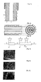
- FIG. 2 is a sectional view showing a foam coaxial cable according to a preferred embodiment of the present invention.
- the foam coaxial cable includes a central conductor 10, an inner skin layer 20 surrounding an outer circumference of the central conductor 10 in compact on the basis of the central conductor 10, an insulation layer 30 surrounding an outer circumference of the inner skin layer 20 in compact, an outer skin layer 40 surrounding an outer circumference of the insulation layer 30 in compact, a shield 50 surrounding the outer skin layer 40, and a jacket 60 surrounding the shield 50.
- the inner skin layer 20, the insulation layer 30, the outer skin layer 40, the shield 50 and the jacket 60 are laminated subsequently on the central conductor 10 coaxially.
- the central conductor 10 is a central line of the foam coaxial cable, which is made of metal material with conductivity and has a hollow cylindrical shape with a diameter of 9 to 19 mm.
- the metal material may selectively adopt copper or its alloy with a thickness of 0.5 mm.
- the central conductor 10 is a transmission line of electromagnetic wave energy, namely high frequency signal, transmitted to/from the foam coaxial cable.
- the inner skin layer 20 is a thin film coating layer provided between the central conductor 10 and the insulation layer 30 to enhance an interfacial adhesive force.
- the inner skin layer 20 contains polymer resin made of the same material as the insulation layer 30.
- the inner skin layer 20 adopts a polymer resin that does not give any influence on dielectric features of the insulation layer 30 but is capable of giving an interfacial characteristic without its own adhesive feature.
- the insulation layer 30 is made of polyethylene resin
- the polymer resin preferably adopts polyolefin resin that is excellent in compatibility.
- the polyethylene resin is a single material or a polymer mixture of at least two materials selected from the group consisting of HDPE (High Density Polyethylene), MDPE (Medium Density Polyethylene), LDPE (Low Density Polyethylene) and LLDPE (Linear Low Density Polyethylene).
- the polyolefin resin is a polymer mixture including polyethylene, polypropylene and/or polyisobutylene.
- the inner skin layer 20 preferably has a thickness in the range of 0.01 to 1 mm, more preferably 0.05 to 0.5 mm.
- the insulation layer 30 is a dielectric layer provided between the central conductor 10 and the shield 50 to prevent any loss of electromagnetic wave energy, and the insulation layer 30 is made of dielectric substance that gives insulation between the central conductor 10 and the shield 50.
- the dielectric substance may selectively adopt foam plastic or plastic composite insulators.
- a polyethylene resin physically foamed is selected to ensure low permittivity and good loss characteristic of the electromagnetic wave energy.
- the insulation layer 30 has a plurality of foam cells with a closed-cell shape.
- the outer skin layer 40 is an overfoaming prevention layer provided between the insulation layer 30 and the shield 50 to prevent overfoaming of the insulation layer 30 and bursting of foam cells provided in the insulation layer 30.
- the outer skin layer 40 contains polymer resin made of the same material as the insulation layer 30.
- the outer skin layer 40 adopts a polymer resin that prevents overfoaming of the insulation layer 30 and allows uniform creation of foam cells in the insulation layer 30 while the insulation layer 30 is foamed.
- the insulation layer 30 is made of polyethylene resin
- the polymer resin may selectively adopt polyethylene, polypropylene, polyethylene terephthalate, or their mixtures.
- the outer skin layer 40 is cooled more rapidly than the insulation layer 30 during the manufacturing process of a foam coaxial cable, explained later, to control overfoaming.
- the outer skin layer 40 has a thickness less than 0.01 mm, a cooling speed is insufficient, so foam cells are burst or lumped.
- the outer skin layer 40 has a thickness greater than 0.5 mm, permittivity is increased to deteriorate a propagation velocity.
- the outer skin layer 40 preferably has a thickness in the range of 0.01 to 0.5 mm, more preferably 0.05 to 0.3 mm.
- the shield 50 is an external conductor provided between the outer skin layer 40 and the jacket 60 to control a loss of electromagnetic wave.
- This external conductor is made of metal material with conductivity and realized as a cylindrical metal tube with a thickness of 0.2 to 0.6 mm.
- This metal material may selectively adopt copper or its alloy with a thickness of 0.2 to 0.6 mm. Also, wrinkled curves are formed on a surface of this metal tube such that its properties are not changed in spite of repeated bending.
- the jacket 60 is a sheath made of polymer material to prevent corrosion of the shield 50 and any external impact.
- the jacket 60 is made of polyolefin material with a thickness of 1 to 2 mm.
- the foam coaxial cable including all of the layers 20 to 60 has a diameter of 25 to 55 mm.
- the inner skin layer 20, the insulation layer 30 and the outer skin layer 40 are subsequently co-extruded onto the central conductor 10 and then laminated thereon with forming concentric circles.
- the central conductor 10 is passed through a first co-extruder 70 to make a first wire member 10' on which an inner skin layer is laminated, and then the first wire member 10' is passed through a second co-extruder 80 to make a second wire member 10" on which an insulation layer and an outer skin layer are subsequently laminated.
- first wire member 10 copper or its alloy with a thickness of 0.5 mm is processed into a ring shape to make a central conductor 10 having a hollow cylindrical shape with a diameter of 9 to 19 mm. And then, the central conductor 10 is progressed in an advancing direction of the wire member at a predetermined speed and then supplied to the first co-extruder 70 provided with a first resin supplier 71. At this time, polyolefin resin is put into the first resin supplier 71.
- the central conductor 10 supplied to the first co-extruder 70 is co-extruded such that an inner skin layer is laminated on its outer circumference, and then the central conductor 10 is supplied to the second co-extruder 80. That is to say, polyolefin resin in a melted state is coated on the outer circumference of the central conductor 10 as a thin film with a thickness of 0.01 to 1 mm such that the central conductor 10 is made into the first wire member 10'.
- the first co-extruder 70 is set such that its inside is kept at temperature of 140°C and pressure of 100 bar, and a speed of the central conductor 10 passing through the first co-extruder 70 is set to be 10 m/min.
- the first wire member 10' supplied to the second co-extruder 80 is co-extruded such that an insulation layer and an outer skin layer are laminated on its outer circumference.
- the second co-extruder 80 is provided with a second resin supplier 81 and a third resin supplier 82.
- 85 wt% of HDPE and 15 wt% of LDPE are put into the second resin supplier 81, and polymer resin including polyethylene resin, polypropylene resin and polyethylene terephthalate resin is put into the second resin supplier 82.
- the first wire member 10' supplied to the second co-extruder 70 is successively doubly co-extruded such that an insulation layer and an outer skin layer are subsequently laminated on its outer circumference.
- the outer skin layer is rapidly cooled while passing through a nozzle 83, thereby controlling overfoaming while foam cells are created in the insulation layer, ensuring uniform creation of the foam cells in the insulation layer, and making the foam cells adjacent to each other.
- the foam cells have a size of 100 to 1000 ⁇ on the basis of an average diameter of long and short axes in a closed-cell shape.
- the second co-extruder 80 is set such that its inside is kept at temperature of 140°C and pressure of 100 bar, and a speed of the first wire member 10' that passes through the second co-extruder 80 is set to be 10 m/min.
- a shield and a sheath are subsequently laminated on the second wire member 10" to make a foam coaxial cable, which is however well known in the art and thus not described in detail here.
- the foam coaxial cable manufactured as above may have an insulation layer that has foam cells with a uniform size, as explained below with reference to FIG. 4 to 6 .
- FIG. 4 is a photograph showing sections of the insulation layer and the outer skin layer according to the preferred embodiment of the present invention
- FIGs. 5 and 6 are photographs showing sections of insulation layers according to comparative examples.
- foam cells in the insulation layer according to the present invention have closed pores with uniform size and high degree of foam.
- the foam cells are successively formed adjacently with each other with keeping the closed pores, respectively.
- the inner skin layer and the outer skin layer that form boundaries with the insulation layer contain polymer resin of the same composition, and there is no deformation of foam cells in the boundaries.
- conventional foam cells according to the comparative examples are burst without keeping closed pores, elongated in association with adjacent foam cells, or sparsely created without being successively adjacent to each other.
- FIG. 7 is a graph showing a loss characteristic of the foam coaxial cable according to the preferred embodiment of the present invention
- FIG. 8 is a graph showing a loss characteristic of a foam coaxial cable according to the comparative example.
- the foam coaxial cable of the present invention has improved dielectric and loss characteristics due to uniform foaming, so attenuation compared frequency is 5.4 dB at 2 GHz, and 6.9 dB at 3 GHz.
- FIG. 8 in the conventional foam coaxial cable, as frequency is increased, a loss is also increased due to irregular foaming, so attenuation compared with frequency is 6.15 dB at 2 GHz, and 8.03 dB at 3 GHz.
- the foam coaxial cable of the present invention shows 10% improvement in its loss characteristic in comparison to the conventional one.
- the foam coaxial cable of the present invention since the foam coaxial cable of the present invention is provided with the inner skin layer and the outer skin layer, the cable has an improved interfacial adhesive force between the central conductor and the insulation layer and an improved degree of foam of the foam cells, and also enables to propagate ultra high frequency of GHz level without any signal interference.
- the degree of foam of the insulation layer formed between the inner and outer skin layers is improved, it is easy to make a large-caliber coaxial cable and propagate a large amount of signals at a super-high speed.
- the foam coaxial cable of the present invention may control generation of group delay and thus ensure good signal characteristics.
Landscapes
- Engineering & Computer Science (AREA)
- Manufacturing & Machinery (AREA)
- Communication Cables (AREA)
Description
- The present invention relates to a foam coaxial cable, and more particularly to a coaxial cable having excellent propagation properties with a reduced loss caused by signal propagation by improving an intercalated structure of the coaxial cable to give better permittivity.
- Generally, a coaxial cable is a transmission line including a central conductor for transmitting signals, and a shield coaxially formed on the central conductor. Seeing the inside section of the line, the central conductor and the shield are coaxially arranged, and an insulation layer having a dielectric feature is formed between the central conductor and the shield.
- Various kinds of coaxial cables with various sizes have been developed, and such a coaxial cable is advantageous since attenuation of signal and change of propagation delay caused by frequency are small owing to its structural features, a large amount of data may be transmitted in a lump, and various coaxial cables may be received in the same cable while ensuring little leakage of signal among them.
- An impedance characteristic is the most essential factor of the coaxial cable, and an impedance value is decided based on the following Equation 1. At this time, in the Equation 1, Z0 is a characteristic impedance, ε is a permittivity, d is a diameter of the central conductor, and D is an inner diameter of the shield.

- As seen from the Equation 1, factors determining a characteristic impedance includes a permittivity, a diameter of the central conductor, and a diameter of the shield. At this time, the permittivity is increased or decreased depending on the degree of foam of the insulation layer, and a propagation velocity is increased or decreased depending on the permittivity. Here, the propagation velocity satisfies the following
Equation 2. At this time, in the followingEquation 2, νp is a propagation velocity, ε is a permittivity after foaming, εr,sol is a permittivity before foaming, ρexp is a density after foaming, and ρsol is a density before foaming.

- As seen from the
Equation 2, a permittivity is lowered as the degree of foam is increased, and a propagation velocity is improved as the permittivity is lowered. That is to say, the loss characteristic depending on signal propagation is improved. At this time, as foam cells composed in an insulation layer after foaming have higher density and uniformity, the degree of foam is increased. - Meanwhile, to improve the substantial loss characteristic of the coaxial cable, the diameters of the central conductor and the shield should not be nearly increased in a generally used cable. That is to say, if a propagation frequency reaches a high level of several GHz, the coaxial cable is confronted with a limit of high frequency due to the TEM (Transverse Electro Magnetic) mode. In addition, in case the materials of the central conductor and the shield are substituted with metal having excellent conductive properties, its performance in comparison to a manufacture cost is inefficient. Thus, a desirable solution for improving the loss characteristic of the coaxial cable is to improve permittivity and structure of the insulation layer.
- A coaxial cable is disclosed in
EP 1457996 A2 . - Recent studies for coaxial cables are directed to improving a structure between a central conductor and a shield and thus improving propagation features in order to reduce an energy loss caused by signal propagation.
US 6,912,777 andUS 4,866,212 disclose a coaxial cable in which an air layer with a lowest permittivity is arranged to surround the central conductor. In addition, as shown inFIG. 1 , a wrinkledshield 3 is provided to surround a central conductor 1 and ashield 2, thereby improving a loss characteristic according to signal propagation. - Also,
US 6,130,385 ,US 4,965,412 andUS 2003/0051897 disclose a technique for improving a loss characteristic according to signal propagation by providing a metal layer or a film layer deposited with metal, which excellently shields electromagnetic wave, to an inner or outer side of the shield. - In addition,
JP 1997-141990 JP 1998-217484 JP 2001-387541 - The above conventional techniques improve a loss characteristic in consideration of diameter and material of the central conductor and the shield, but they are confronted with a limit of high frequency or insufficient in performance compared with a manufacture cost. Also, the conventional techniques have a problem that a propagation characteristic is deteriorated due to low density and uniformity of foam cells since foam cells have irregular sizes or lumps with each other. Moreover, a low degree of foam causes local differences of permittivity and unbalanced outer diameters of the coaxial cable, and it also acts as a limitation factor in making a coaxial cable with a large caliber.
- Recently, studies for lowering a permittivity by foaming polymer material are frequently progressed, and many efforts are consumed for using a high frequency of several hundred MHz or several GHz as a usable frequency so as to propagate more information. Accordingly, it is an important issue to develop a polymer insulation layer with a low loss.
- The present invention is designed in consideration of the above problems, and therefore it is an object of the invention to provide a foam coaxial cable having no local difference of permittivity with improved loss characteristic according to high frequency propagation by improving an interfacial adhesive force and foam uniformity of a foam insulation layer for the foam coaxial cable.
- In order to accomplish the above object, the present invention provides a foam coaxial cable. according to claim 1.
- Preferably, the central conductor is metal composed of copper or its alloy with a thickness of 0.5 mm, and the central conductor is a hollow cylinder with an outer diameter of 9 to 19 mm.
- In the present invention, the inner skin layer may be a thin film coating layer made of polyolefin resin with a thickness of 0.01 to 1 mm.
- According to the present invention, the insulation layer may be a foam insulation layer made of polyethylene resin with a thickness of 5 to 15 mm.
- Preferably, the physical foaming is conducted in a way of injecting a foaming gas into a polyethylene resin to reach a supersaturated state, and the foaming gas is a mixed gas including carbon dioxide, nitrogen and Freon.
- According to the present invention, the outer skin layer may be an overfoaming prevention layer made of polymer resin with a thickness of 0.01 to 0.5 mm.
- Preferably, the polymer resin is made of a single material or a mixture of at least two materials selected from the group consisting of polyethylene resin, polypropylene resin and polyethylene terephthalate resin.
- In another aspect of the present invention, there is also provided a method for manufacturing a foam coaxial cable according to
claim 6. - Preferably, the physical foaming in the step (B) is conducted in a way of injecting a mixed gas of carbon dioxide, nitrogen and Freon into a polyethylene resin in a melted state to reach a supersaturated state such that a plurality of foam cells are created in the insulation layer.
- More preferably, the polymer resin of the step (C) is made of a single material or a mixture of at least two materials selected from the group consisting of polyethylene resin, polypropylene resin and polyethylene terephthalate resin.
- Other objects and aspects of the present invention will become apparent from the following description of embodiments with reference to the accompanying drawing in which:
-
FIG. 1 is a sectional view schematically showing a conventional coaxial cable; -
FIG. 2 is a sectional view showing a foam coaxial cable according to a preferred embodiment of the present invention; -
FIG. 3 is a schematic view showing a co-extruder used for manufacturing the foam coaxial cable according to the preferred embodiment of the present invention; -
FIG. 4 is a photograph showing sections of an insulation layer and an outer skin layer according to a preferred embodiment of the present invention; -
FIGs. 5 and 6 are photographs showing sections of insulation layers according to comparative examples; -
FIG. 7 is a graph showing a loss characteristic of the foam coaxial cable according to the preferred embodiment of the present invention; and -
FIG. 8 is a graph showing a loss characteristic of a foam coaxial cable according to a comparative example. - < Reference Numerals of Essential Parts in the Drawings >
- 10: central conductor 20: inner skin layer
- 30: insulation layer 40: outer skin layer
- 50: shield 60: jacket
- Hereinafter, preferred embodiments of the present invention will be described in detail with reference to the accompanying drawings. Prior to the description, it should be understood that the terms used in the specification and the appended claims should not be construed as limited to general and dictionary meanings, but interpreted based on the meanings and concepts corresponding to technical aspects of the present invention on the basis of the principle that the inventor is allowed to define terms appropriately for the best explanation. Therefore, the description proposed herein is just a preferable example for the purpose of illustrations only, not intended to limit the scope of the invention, so it should be understood that other equivalents and modifications could be made thereto without departing from the spirit and scope of the invention.
-
FIG. 2 is a sectional view showing a foam coaxial cable according to a preferred embodiment of the present invention. - As shown in
FIG. 2 , the foam coaxial cable includes acentral conductor 10, aninner skin layer 20 surrounding an outer circumference of thecentral conductor 10 in compact on the basis of thecentral conductor 10, aninsulation layer 30 surrounding an outer circumference of theinner skin layer 20 in compact, anouter skin layer 40 surrounding an outer circumference of theinsulation layer 30 in compact, ashield 50 surrounding theouter skin layer 40, and ajacket 60 surrounding theshield 50. At this time, theinner skin layer 20, theinsulation layer 30, theouter skin layer 40, theshield 50 and thejacket 60 are laminated subsequently on thecentral conductor 10 coaxially. - The
central conductor 10 is a central line of the foam coaxial cable, which is made of metal material with conductivity and has a hollow cylindrical shape with a diameter of 9 to 19 mm. The metal material may selectively adopt copper or its alloy with a thickness of 0.5 mm. At this time, thecentral conductor 10 is a transmission line of electromagnetic wave energy, namely high frequency signal, transmitted to/from the foam coaxial cable. - The
inner skin layer 20 is a thin film coating layer provided between thecentral conductor 10 and theinsulation layer 30 to enhance an interfacial adhesive force. Theinner skin layer 20 contains polymer resin made of the same material as theinsulation layer 30. - In this embodiment, the
inner skin layer 20 adopts a polymer resin that does not give any influence on dielectric features of theinsulation layer 30 but is capable of giving an interfacial characteristic without its own adhesive feature. In case theinsulation layer 30 is made of polyethylene resin, the polymer resin preferably adopts polyolefin resin that is excellent in compatibility. - Here, the polyethylene resin is a single material or a polymer mixture of at least two materials selected from the group consisting of HDPE (High Density Polyethylene), MDPE (Medium Density Polyethylene), LDPE (Low Density Polyethylene) and LLDPE (Linear Low Density Polyethylene). Also, the polyolefin resin is a polymer mixture including polyethylene, polypropylene and/or polyisobutylene.
- At this time, if the
inner skin layer 20 has a thickness less than 0.01 mm, it is difficult to ensure uniform coating on the outer circumference of thecentral conductor 10. In addition, if the thin film coating layer has a thickness greater than 1 mm, a permittivity is increased to deteriorate a propagation velocity. Thus, theinner skin layer 20 preferably has a thickness in the range of 0.01 to 1 mm, more preferably 0.05 to 0.5 mm. - The
insulation layer 30 is a dielectric layer provided between thecentral conductor 10 and theshield 50 to prevent any loss of electromagnetic wave energy, and theinsulation layer 30 is made of dielectric substance that gives insulation between thecentral conductor 10 and theshield 50. The dielectric substance may selectively adopt foam plastic or plastic composite insulators. Preferably, a polyethylene resin physically foamed is selected to ensure low permittivity and good loss characteristic of the electromagnetic wave energy. - In this embodiment, the
insulation layer 30 has a plurality of foam cells with a closed-cell shape. - The
outer skin layer 40 is an overfoaming prevention layer provided between theinsulation layer 30 and theshield 50 to prevent overfoaming of theinsulation layer 30 and bursting of foam cells provided in theinsulation layer 30. Theouter skin layer 40 contains polymer resin made of the same material as theinsulation layer 30. - In this embodiment, the
outer skin layer 40 adopts a polymer resin that prevents overfoaming of theinsulation layer 30 and allows uniform creation of foam cells in theinsulation layer 30 while theinsulation layer 30 is foamed. In case theinsulation layer 30 is made of polyethylene resin, the polymer resin may selectively adopt polyethylene, polypropylene, polyethylene terephthalate, or their mixtures. - Here, the
outer skin layer 40 is cooled more rapidly than theinsulation layer 30 during the manufacturing process of a foam coaxial cable, explained later, to control overfoaming. However, if theouter skin layer 40 has a thickness less than 0.01 mm, a cooling speed is insufficient, so foam cells are burst or lumped. In addition, of theouter skin layer 40 has a thickness greater than 0.5 mm, permittivity is increased to deteriorate a propagation velocity. Thus, theouter skin layer 40 preferably has a thickness in the range of 0.01 to 0.5 mm, more preferably 0.05 to 0.3 mm. - The
shield 50 is an external conductor provided between theouter skin layer 40 and thejacket 60 to control a loss of electromagnetic wave. This external conductor is made of metal material with conductivity and realized as a cylindrical metal tube with a thickness of 0.2 to 0.6 mm. This metal material may selectively adopt copper or its alloy with a thickness of 0.2 to 0.6 mm. Also, wrinkled curves are formed on a surface of this metal tube such that its properties are not changed in spite of repeated bending. - The
jacket 60 is a sheath made of polymer material to prevent corrosion of theshield 50 and any external impact. Thejacket 60 is made of polyolefin material with a thickness of 1 to 2 mm. - In this embodiment, the foam coaxial cable including all of the
layers 20 to 60 has a diameter of 25 to 55 mm. - Among the components of the above foam coaxial cable, the
inner skin layer 20, theinsulation layer 30 and theouter skin layer 40 are subsequently co-extruded onto thecentral conductor 10 and then laminated thereon with forming concentric circles. Now, a method for manufacturing the foam coaxial cable according to the present invention will be explained as follows with reference to a co-extruder shown inFIG. 3 . - As shown in
FIG. 3 , thecentral conductor 10 is passed through a first co-extruder 70 to make a first wire member 10' on which an inner skin layer is laminated, and then the first wire member 10' is passed through a second co-extruder 80 to make asecond wire member 10" on which an insulation layer and an outer skin layer are subsequently laminated. - First, seeing the process of making the first wire member 10', copper or its alloy with a thickness of 0.5 mm is processed into a ring shape to make a
central conductor 10 having a hollow cylindrical shape with a diameter of 9 to 19 mm. And then, thecentral conductor 10 is progressed in an advancing direction of the wire member at a predetermined speed and then supplied to the first co-extruder 70 provided with afirst resin supplier 71. At this time, polyolefin resin is put into thefirst resin supplier 71. - The
central conductor 10 supplied to the first co-extruder 70 is co-extruded such that an inner skin layer is laminated on its outer circumference, and then thecentral conductor 10 is supplied to the second co-extruder 80. That is to say, polyolefin resin in a melted state is coated on the outer circumference of thecentral conductor 10 as a thin film with a thickness of 0.01 to 1 mm such that thecentral conductor 10 is made into the first wire member 10'. - In this embodiment, the first co-extruder 70 is set such that its inside is kept at temperature of 140°C and pressure of 100 bar, and a speed of the
central conductor 10 passing through the first co-extruder 70 is set to be 10 m/min. - Then, the first wire member 10' supplied to the second co-extruder 80 is co-extruded such that an insulation layer and an outer skin layer are laminated on its outer circumference. Here, the second co-extruder 80 is provided with a
second resin supplier 81 and athird resin supplier 82. At this time, 85 wt% of HDPE and 15 wt% of LDPE are put into thesecond resin supplier 81, and polymer resin including polyethylene resin, polypropylene resin and polyethylene terephthalate resin is put into thesecond resin supplier 82. - The first wire member 10' supplied to the second co-extruder 70 is successively doubly co-extruded such that an insulation layer and an outer skin layer are subsequently laminated on its outer circumference.
- That is to say, physically foamed polyethylene resin is laminated on the outer circumference of the first wire member 10' in a thickness of 6 to 14 mm, and then polymer resin in a melted state is coated on its outer circumference as a thin film with a thickness of 0.01 to 0.5 mm, thereby making the
second wire member 10". At this time, this foaming is performed in a way that a mixed gas supplied from outside is injected into the polyethylene resin in a melted state till an overfoaming state. - In this embodiment, the outer skin layer is rapidly cooled while passing through a nozzle 83, thereby controlling overfoaming while foam cells are created in the insulation layer, ensuring uniform creation of the foam cells in the insulation layer, and making the foam cells adjacent to each other. At this time, the foam cells have a size of 100 to 1000 □ on the basis of an average diameter of long and short axes in a closed-cell shape.
- In this embodiment, the second co-extruder 80 is set such that its inside is kept at temperature of 140°C and pressure of 100 bar, and a speed of the first wire member 10' that passes through the second co-extruder 80 is set to be 10 m/min.
- After that, a shield and a sheath are subsequently laminated on the
second wire member 10" to make a foam coaxial cable, which is however well known in the art and thus not described in detail here. - The foam coaxial cable manufactured as above may have an insulation layer that has foam cells with a uniform size, as explained below with reference to
FIG. 4 to 6 . At this time,FIG. 4 is a photograph showing sections of the insulation layer and the outer skin layer according to the preferred embodiment of the present invention, andFIGs. 5 and 6 are photographs showing sections of insulation layers according to comparative examples. - Referring to
FIG. 4 , foam cells in the insulation layer according to the present invention have closed pores with uniform size and high degree of foam. In addition, the foam cells are successively formed adjacently with each other with keeping the closed pores, respectively. Also, the inner skin layer and the outer skin layer that form boundaries with the insulation layer contain polymer resin of the same composition, and there is no deformation of foam cells in the boundaries. - Meanwhile, referring to
FIGs. 5 and 6 , conventional foam cells according to the comparative examples are burst without keeping closed pores, elongated in association with adjacent foam cells, or sparsely created without being successively adjacent to each other. - As density and uniformity of the foam cells are improved, permittivity is lowered. Also, as the permittivity is lowered, a loss characteristic according to signal propagation is improved. It will be explained below with reference to
FIGs. 7 and 8 . At this time,FIG. 7 is a graph showing a loss characteristic of the foam coaxial cable according to the preferred embodiment of the present invention, andFIG. 8 is a graph showing a loss characteristic of a foam coaxial cable according to the comparative example. - Seeing
FIG. 7 , the foam coaxial cable of the present invention has improved dielectric and loss characteristics due to uniform foaming, so attenuation compared frequency is 5.4 dB at 2 GHz, and 6.9 dB at 3 GHz. Meanwhile, seeingFIG. 8 , in the conventional foam coaxial cable, as frequency is increased, a loss is also increased due to irregular foaming, so attenuation compared with frequency is 6.15 dB at 2 GHz, and 8.03 dB at 3 GHz. - As understood from the above embodiment and comparative example, the foam coaxial cable of the present invention shows 10% improvement in its loss characteristic in comparison to the conventional one.
- The present invention has been described in detail. However, it should be understood that the detailed description and specific examples, while indicating preferred embodiments of the invention, are given by way of illustration only, since various changes and modifications within the spirit and scope of the invention will become apparent to those skilled in the art from this detailed description.
- As described above, since the foam coaxial cable of the present invention is provided with the inner skin layer and the outer skin layer, the cable has an improved interfacial adhesive force between the central conductor and the insulation layer and an improved degree of foam of the foam cells, and also enables to propagate ultra high frequency of GHz level without any signal interference.
- Also, since the degree of foam of the insulation layer formed between the inner and outer skin layers is improved, it is easy to make a large-caliber coaxial cable and propagate a large amount of signals at a super-high speed.
- In addition, since the inner and outer skin layers control abnormal growth of foam cells and do not cause any difference of dielectric characteristics between the central conductor and the shield, the foam coaxial cable of the present invention may control generation of group delay and thus ensure good signal characteristics.
Claims (8)
- A foam coaxial cable, comprising:a central conductor (10), an inner skin layer (20) surrounding an outer circumference of the central conductor (10) on the basis of the central conductor (10),an insulation layer (30) surrounding an outer circumference of the inner skin layer (20) on the basis of the central conductor (10) and made of polyethylene resin containing a plurality of foam cells uniformly formed therein; wherein the inner skin layer (20) is made of polyolefin resin, an outer skin layer (40) surrounding an outer circumference of the insulation layer (30) on the basis of the central conductor (10), wherein the inner skin layer (20) and the outer skin layer (40) form boundaries with the insulation layer (30), a shield (50) surrounding the outer skin layer (40) on the basis of the central conductor (10), and a jacket (60) surrounding the shield (50); is characterized in that:the foam cells have closed pores and are successively formed adjacently with each other with keeping the closed pores, and the inner skin layer (20) and the outer skin layer (40) contain polymer resin of the same composition.
- The foam coaxial cable according to claim 1,
wherein the central conductor is a hollow cylinder with an outer diameter of 9 to 19 mm. - The foam coaxial cable according to claim 1 or 2,
wherein the inner skin layer is a thin film coating layer with a thickness of 0.01 to 1 mm. - The foam coaxial cable according to claim 3,
wherein the outer skin layer is an overfoaming prevention layer with a thickness of 0.01 to 0.5 mm. - The foam coaxial cable according to claim 4,
wherein the insulation layer is a foam insulation layer with a thickness of 5 to 15 mm. - A method for manufacturing a foam coaxial cable,
comprising: (A) forming an inner skin layer (20) on an outer circumference of a central conductor (10), wherein the inner skin layer (20) is made of polyolefin resin, (B) forming an insulation layer (30) by co-extruding a polyethylene resin on an outer circumference of the inner skin (20), (C) forming an outer skin layer (40) on an outer circumference of the insulation layer (30), wherein the inner skin layer (20) and the outer skin layer (40) form boundaries with the insulation layer (30) and (D) forming a shield (50) and a jacket (60) on an outer circumference of the outer skin layer (40); is characterized in that:the insulation layer (30) contains a plurality of foam cells formed therein, the foam cells have closed pores and are successively formed adjacently with each other with keeping the closed pores, and the inner skin layer (20) and the outer skin layer (40) contain polymer resin of the same composition. - The method for manufacturing a foam coaxial cable according to claim 6, wherein the foam cells in the insulation layer are created by injecting a mixed gas of carbon dioxide, nitrogen and Freon into a polyethylene resin in a melted state
- The method for manufacturing a foam coaxial cable according to claim 6 or 7,
wherein the inner skin layer has a thickness of 0.01 to 0.1mm, the insulation layer has a thickness of 5 to 15mm, and the outer skin layer has a thickness of 0.01 to 0.5mm.
Applications Claiming Priority (2)
| Application Number | Priority Date | Filing Date | Title |
|---|---|---|---|
| KR1020060077650A KR100816587B1 (en) | 2006-08-17 | 2006-08-17 | Foamed coaxial cable and its manufacturing method |
| PCT/KR2007/003858 WO2008020694A1 (en) | 2006-08-17 | 2007-08-10 | Foam coaxial cable and method for manufacturing the same |
Publications (3)
| Publication Number | Publication Date |
|---|---|
| EP2057640A1 EP2057640A1 (en) | 2009-05-13 |
| EP2057640A4 EP2057640A4 (en) | 2012-03-21 |
| EP2057640B1 true EP2057640B1 (en) | 2013-02-13 |
Family
ID=39082200
Family Applications (1)
| Application Number | Title | Priority Date | Filing Date |
|---|---|---|---|
| EP07793465A Active EP2057640B1 (en) | 2006-08-17 | 2007-08-10 | Foam coaxial cable and method for manufacturing the same |
Country Status (5)
| Country | Link |
|---|---|
| US (1) | US7897874B2 (en) |
| EP (1) | EP2057640B1 (en) |
| KR (1) | KR100816587B1 (en) |
| AU (1) | AU2007285158B2 (en) |
| WO (1) | WO2008020694A1 (en) |
Cited By (2)
| Publication number | Priority date | Publication date | Assignee | Title |
|---|---|---|---|---|
| WO2019226987A1 (en) * | 2018-05-25 | 2019-11-28 | Samtec, Inc. | Electrical cable with dielectric foam |
| TWI924021B (en) | 2018-05-25 | 2026-05-01 | 美商山姆科技公司 | Electrical cable and waveguide with dielectric foam and method of propagating rf signal |
Families Citing this family (20)
| Publication number | Priority date | Publication date | Assignee | Title |
|---|---|---|---|---|
| KR100948433B1 (en) * | 2007-10-15 | 2010-03-17 | 엘에스전선 주식회사 | High foam coaxial cable |
| US20100300725A1 (en) * | 2009-05-28 | 2010-12-02 | Akinari Nakayama | Electric-wire cable equipped with foamed insulator |
| JP5825270B2 (en) * | 2012-01-25 | 2015-12-02 | 住友電気工業株式会社 | Multi-core cable |
| JP2013214499A (en) * | 2012-03-07 | 2013-10-17 | Hitachi Cable Ltd | Differential transmission cable and manufacturing method therefor |
| JP5811976B2 (en) * | 2012-09-14 | 2015-11-11 | 日立金属株式会社 | Foamed coaxial cable and multi-core cable |
| JP5920278B2 (en) * | 2013-04-15 | 2016-05-18 | 日立金属株式会社 | Differential signal transmission cable and multi-pair differential signal transmission cable |
| JP2015002100A (en) * | 2013-06-17 | 2015-01-05 | 日立金属株式会社 | Coaxial cable |
| CN104036853A (en) * | 2014-05-30 | 2014-09-10 | 江苏艾立可电子科技有限公司 | Anti-extrusion deformation foamed radio frequency cable |
| KR20160038331A (en) * | 2014-09-30 | 2016-04-07 | 엘에스전선 주식회사 | Coaxial cable |
| WO2017177319A1 (en) | 2016-04-13 | 2017-10-19 | Acceleware Ltd. | Apparatus and methods for electromagnetic heating of hydrocarbon formations |
| CN105931761B (en) * | 2016-04-28 | 2017-12-15 | 杭州富通电线电缆有限公司 | A coaxial cable production process |
| CN107248436B (en) * | 2016-04-28 | 2018-12-18 | 杭州富通电线电缆有限公司 | A kind of coaxial cable production technology |
| WO2019119128A1 (en) | 2017-12-21 | 2019-06-27 | Acceleware Ltd. | Apparatus and methods for enhancing a coaxial line |
| CA3105830A1 (en) | 2018-07-09 | 2020-01-16 | Acceleware Ltd. | Apparatus and methods for connecting sections of a coaxial line |
| CN114450849B (en) | 2019-05-14 | 2024-08-27 | 申泰公司 | Wireless RF Waveguide Cable Assemblies |
| CN110459350B (en) * | 2019-08-02 | 2024-07-09 | 上海福尔欣线缆有限公司 | Coaxial data cable for intelligent driving system of vehicle and manufacturing method |
| CN111029698B (en) * | 2019-12-12 | 2025-01-17 | 安徽联嘉祥特种电缆有限公司 | Leaky coaxial cable for 5G signal transmission |
| JP7384095B2 (en) * | 2020-03-27 | 2023-11-21 | 住友電装株式会社 | wire harness |
| KR20240003365A (en) * | 2022-06-30 | 2024-01-09 | 엘에스전선 주식회사 | Coaxial cable for nuclear power plant |
| WO2025074254A1 (en) * | 2023-10-06 | 2025-04-10 | 3M Innovative Properties Company | Shielded electrical cable and method of making the same |
Family Cites Families (20)
| Publication number | Priority date | Publication date | Assignee | Title |
|---|---|---|---|---|
| US4886212A (en) | 1985-03-20 | 1989-12-12 | Turbo Tek Enterprises, Inc. | Spraying device having controlled additive fluid feed and a telescoping spray tube assembly |
| US4965412A (en) | 1989-04-06 | 1990-10-23 | W. L. Gore & Associates, Inc. | Coaxial electrical cable construction |
| FR2746539B1 (en) * | 1996-03-21 | 1998-05-22 | Kertscher Sa E | METHOD FOR MANUFACTURING COAXIAL CABLES |
| JPH09270631A (en) * | 1996-03-28 | 1997-10-14 | Fujikura Ltd | Leaky coaxial cable |
| FI962715A7 (en) | 1996-07-01 | 1998-01-02 | Nk Cables Oy | Coaxial high-frequency cable and its insulation |
| JP3424788B2 (en) | 1996-07-25 | 2003-07-07 | 矢崎総業株式会社 | Coaxial cable and method of manufacturing coaxial cable |
| JPH10334750A (en) | 1997-05-30 | 1998-12-18 | Hitachi Cable Ltd | Bend-resistant extra fine multi-core coaxial cable |
| SE9802087D0 (en) * | 1998-06-12 | 1998-06-12 | Borealis Polymers Oy | An insulating composition for communication cables |
| JP2000048653A (en) | 1998-07-31 | 2000-02-18 | Hitachi Cable Ltd | High-speed transmission coaxial cable and method of manufacturing the same |
| US6417454B1 (en) * | 2000-06-21 | 2002-07-09 | Commscope, Inc. | Coaxial cable having bimetallic outer conductor |
| CA2404271A1 (en) | 2001-09-17 | 2003-03-17 | Nordx/Cdt, Inc. | Mini coaxial cable for digital network |
| JP2003187649A (en) | 2001-12-20 | 2003-07-04 | Hitachi Cable Ltd | Semi-flexible coaxial cable |
| US6683256B2 (en) * | 2002-03-27 | 2004-01-27 | Ta-San Kao | Structure of signal transmission line |
| US6693241B2 (en) | 2002-04-24 | 2004-02-17 | Andrew Corporation | Low-cost, high performance, moisture-blocking, coaxial cable and manufacturing method |
| EP1429346B1 (en) * | 2002-12-12 | 2009-03-25 | Borealis Technology Oy | Coaxial cable comprising dielectric material |
| US6756538B1 (en) * | 2003-01-29 | 2004-06-29 | Conductores Monterrey S.A. De C.V. | Coaxial cable having improved mechanical and electrical properties |
| MXPA03002208A (en) * | 2003-03-13 | 2004-09-15 | Servicios Condumex Sa | Dry water-resistant coaxial cable and manufacturing method of the same. |
| CN100416711C (en) * | 2003-05-22 | 2008-09-03 | 平河福泰克株式会社 | Foam coaxial cable and method of manufacturing the same |
| MXPA06013684A (en) * | 2004-05-26 | 2007-03-01 | Dow Global Technologies Inc | Coaxial cable with foamed insulation. |
| KR100948433B1 (en) * | 2007-10-15 | 2010-03-17 | 엘에스전선 주식회사 | High foam coaxial cable |
-
2006
- 2006-08-17 KR KR1020060077650A patent/KR100816587B1/en active Active
-
2007
- 2007-08-10 US US12/377,842 patent/US7897874B2/en active Active
- 2007-08-10 WO PCT/KR2007/003858 patent/WO2008020694A1/en not_active Ceased
- 2007-08-10 AU AU2007285158A patent/AU2007285158B2/en active Active
- 2007-08-10 EP EP07793465A patent/EP2057640B1/en active Active
Cited By (3)
| Publication number | Priority date | Publication date | Assignee | Title |
|---|---|---|---|---|
| WO2019226987A1 (en) * | 2018-05-25 | 2019-11-28 | Samtec, Inc. | Electrical cable with dielectric foam |
| TWI845510B (en) * | 2018-05-25 | 2024-06-21 | 美商山姆科技公司 | Electrical cable and waveguide with dielectric foam |
| TWI924021B (en) | 2018-05-25 | 2026-05-01 | 美商山姆科技公司 | Electrical cable and waveguide with dielectric foam and method of propagating rf signal |
Also Published As
| Publication number | Publication date |
|---|---|
| US7897874B2 (en) | 2011-03-01 |
| EP2057640A1 (en) | 2009-05-13 |
| KR100816587B1 (en) | 2008-03-24 |
| AU2007285158B2 (en) | 2011-06-02 |
| AU2007285158A1 (en) | 2008-02-21 |
| WO2008020694A1 (en) | 2008-02-21 |
| US20100230130A1 (en) | 2010-09-16 |
| EP2057640A4 (en) | 2012-03-21 |
Similar Documents
| Publication | Publication Date | Title |
|---|---|---|
| AU2007285158B2 (en) | Foam coaxial cable and method for manufacturing the same | |
| EP1625597B1 (en) | Cable with foamed plastic insulation comprising an ultra-high die swell ratio polymeric material | |
| JP5975334B2 (en) | Foamed resin molded body, foamed insulated wire and cable, and method for producing foamed resin molded body | |
| EP2201579B1 (en) | Highly foamed coaxial cable | |
| US7541542B2 (en) | Micro coaxial cable | |
| CN101944405B (en) | Electric-wire cable provided with foamed insulator | |
| JP4435306B2 (en) | Coaxial high frequency cable and its derivatives | |
| WO2019226987A1 (en) | Electrical cable with dielectric foam | |
| EP0939960A1 (en) | Coaxial cable | |
| US8779293B2 (en) | Coaxial cable | |
| CN105229753B (en) | Insulated wire and coaxial cable | |
| CN102738549A (en) | High-frequency coaxial cable | |
| US8822825B2 (en) | Foamed electric wire and transmission cable having same | |
| WO2008096941A1 (en) | Insulator for coaxial cable, method for preparing the same, and low loss large diameter coaxial cable using the same | |
| CN208208421U (en) | 8k coaxial cable | |
| WO1998043254A1 (en) | Mineral insulated cable | |
| CN114696053A (en) | Circular waveguide transmission line for millimeter wave and method for manufacturing the same | |
| JPH02284314A (en) | Manufacturing method of small diameter highly foamed plastic insulated wire | |
| HK1079333B (en) | Cable with foamed plastic insulation comprising an ultra-high die swell ratio polymeric material | |
| CS247311B1 (en) | High frequency cable with composite insulation |
Legal Events
| Date | Code | Title | Description |
|---|---|---|---|
| PUAI | Public reference made under article 153(3) epc to a published international application that has entered the european phase |
Free format text: ORIGINAL CODE: 0009012 |
|
| 17P | Request for examination filed |
Effective date: 20090316 |
|
| AK | Designated contracting states |
Kind code of ref document: A1 Designated state(s): AT BE BG CH CY CZ DE DK EE ES FI FR GB GR HU IE IS IT LI LT LU LV MC MT NL PL PT RO SE SI SK TR |
|
| AX | Request for extension of the european patent |
Extension state: AL BA HR MK RS |
|
| RIN1 | Information on inventor provided before grant (corrected) |
Inventor name: NAM, GI-JOON Inventor name: PARK, JUNG-WON Inventor name: LEE, DAE-SUNG Inventor name: PARK, CHAN-YONG Inventor name: CHO, BONG-KWON |
|
| A4 | Supplementary search report drawn up and despatched |
Effective date: 20120216 |
|
| RIC1 | Information provided on ipc code assigned before grant |
Ipc: H01B 13/016 20060101AFI20120210BHEP Ipc: H01B 11/18 20060101ALI20120210BHEP |
|
| DAX | Request for extension of the european patent (deleted) | ||
| GRAP | Despatch of communication of intention to grant a patent |
Free format text: ORIGINAL CODE: EPIDOSNIGR1 |
|
| GRAS | Grant fee paid |
Free format text: ORIGINAL CODE: EPIDOSNIGR3 |
|
| GRAA | (expected) grant |
Free format text: ORIGINAL CODE: 0009210 |
|
| AK | Designated contracting states |
Kind code of ref document: B1 Designated state(s): AT BE BG CH CY CZ DE DK EE ES FI FR GB GR HU IE IS IT LI LT LU LV MC MT NL PL PT RO SE SI SK TR |
|
| REG | Reference to a national code |
Ref country code: GB Ref legal event code: FG4D |
|
| REG | Reference to a national code |
Ref country code: AT Ref legal event code: REF Ref document number: 596866 Country of ref document: AT Kind code of ref document: T Effective date: 20130215 |
|
| REG | Reference to a national code |
Ref country code: IE Ref legal event code: FG4D |
|
| REG | Reference to a national code |
Ref country code: DE Ref legal event code: R096 Ref document number: 602007028428 Country of ref document: DE Effective date: 20130411 |
|
| REG | Reference to a national code |
Ref country code: AT Ref legal event code: MK05 Ref document number: 596866 Country of ref document: AT Kind code of ref document: T Effective date: 20130213 |
|
| REG | Reference to a national code |
Ref country code: NL Ref legal event code: VDEP Effective date: 20130213 |
|
| REG | Reference to a national code |
Ref country code: LT Ref legal event code: MG4D |
|
| PG25 | Lapsed in a contracting state [announced via postgrant information from national office to epo] |
Ref country code: BG Free format text: LAPSE BECAUSE OF FAILURE TO SUBMIT A TRANSLATION OF THE DESCRIPTION OR TO PAY THE FEE WITHIN THE PRESCRIBED TIME-LIMIT Effective date: 20130513 Ref country code: SE Free format text: LAPSE BECAUSE OF FAILURE TO SUBMIT A TRANSLATION OF THE DESCRIPTION OR TO PAY THE FEE WITHIN THE PRESCRIBED TIME-LIMIT Effective date: 20130213 Ref country code: IS Free format text: LAPSE BECAUSE OF FAILURE TO SUBMIT A TRANSLATION OF THE DESCRIPTION OR TO PAY THE FEE WITHIN THE PRESCRIBED TIME-LIMIT Effective date: 20130613 Ref country code: ES Free format text: LAPSE BECAUSE OF FAILURE TO SUBMIT A TRANSLATION OF THE DESCRIPTION OR TO PAY THE FEE WITHIN THE PRESCRIBED TIME-LIMIT Effective date: 20130524 Ref country code: LT Free format text: LAPSE BECAUSE OF FAILURE TO SUBMIT A TRANSLATION OF THE DESCRIPTION OR TO PAY THE FEE WITHIN THE PRESCRIBED TIME-LIMIT Effective date: 20130213 Ref country code: AT Free format text: LAPSE BECAUSE OF FAILURE TO SUBMIT A TRANSLATION OF THE DESCRIPTION OR TO PAY THE FEE WITHIN THE PRESCRIBED TIME-LIMIT Effective date: 20130213 |
|
| PG25 | Lapsed in a contracting state [announced via postgrant information from national office to epo] |
Ref country code: FI Free format text: LAPSE BECAUSE OF FAILURE TO SUBMIT A TRANSLATION OF THE DESCRIPTION OR TO PAY THE FEE WITHIN THE PRESCRIBED TIME-LIMIT Effective date: 20130213 Ref country code: BE Free format text: LAPSE BECAUSE OF FAILURE TO SUBMIT A TRANSLATION OF THE DESCRIPTION OR TO PAY THE FEE WITHIN THE PRESCRIBED TIME-LIMIT Effective date: 20130213 Ref country code: LV Free format text: LAPSE BECAUSE OF FAILURE TO SUBMIT A TRANSLATION OF THE DESCRIPTION OR TO PAY THE FEE WITHIN THE PRESCRIBED TIME-LIMIT Effective date: 20130213 Ref country code: SI Free format text: LAPSE BECAUSE OF FAILURE TO SUBMIT A TRANSLATION OF THE DESCRIPTION OR TO PAY THE FEE WITHIN THE PRESCRIBED TIME-LIMIT Effective date: 20130213 Ref country code: GR Free format text: LAPSE BECAUSE OF FAILURE TO SUBMIT A TRANSLATION OF THE DESCRIPTION OR TO PAY THE FEE WITHIN THE PRESCRIBED TIME-LIMIT Effective date: 20130514 Ref country code: PL Free format text: LAPSE BECAUSE OF FAILURE TO SUBMIT A TRANSLATION OF THE DESCRIPTION OR TO PAY THE FEE WITHIN THE PRESCRIBED TIME-LIMIT Effective date: 20130213 Ref country code: PT Free format text: LAPSE BECAUSE OF FAILURE TO SUBMIT A TRANSLATION OF THE DESCRIPTION OR TO PAY THE FEE WITHIN THE PRESCRIBED TIME-LIMIT Effective date: 20130613 |
|
| PG25 | Lapsed in a contracting state [announced via postgrant information from national office to epo] |
Ref country code: RO Free format text: LAPSE BECAUSE OF FAILURE TO SUBMIT A TRANSLATION OF THE DESCRIPTION OR TO PAY THE FEE WITHIN THE PRESCRIBED TIME-LIMIT Effective date: 20130213 Ref country code: NL Free format text: LAPSE BECAUSE OF FAILURE TO SUBMIT A TRANSLATION OF THE DESCRIPTION OR TO PAY THE FEE WITHIN THE PRESCRIBED TIME-LIMIT Effective date: 20130213 Ref country code: EE Free format text: LAPSE BECAUSE OF FAILURE TO SUBMIT A TRANSLATION OF THE DESCRIPTION OR TO PAY THE FEE WITHIN THE PRESCRIBED TIME-LIMIT Effective date: 20130213 Ref country code: CZ Free format text: LAPSE BECAUSE OF FAILURE TO SUBMIT A TRANSLATION OF THE DESCRIPTION OR TO PAY THE FEE WITHIN THE PRESCRIBED TIME-LIMIT Effective date: 20130213 Ref country code: SK Free format text: LAPSE BECAUSE OF FAILURE TO SUBMIT A TRANSLATION OF THE DESCRIPTION OR TO PAY THE FEE WITHIN THE PRESCRIBED TIME-LIMIT Effective date: 20130213 Ref country code: DK Free format text: LAPSE BECAUSE OF FAILURE TO SUBMIT A TRANSLATION OF THE DESCRIPTION OR TO PAY THE FEE WITHIN THE PRESCRIBED TIME-LIMIT Effective date: 20130213 |
|
| PLBE | No opposition filed within time limit |
Free format text: ORIGINAL CODE: 0009261 |
|
| STAA | Information on the status of an ep patent application or granted ep patent |
Free format text: STATUS: NO OPPOSITION FILED WITHIN TIME LIMIT |
|
| PG25 | Lapsed in a contracting state [announced via postgrant information from national office to epo] |
Ref country code: IT Free format text: LAPSE BECAUSE OF FAILURE TO SUBMIT A TRANSLATION OF THE DESCRIPTION OR TO PAY THE FEE WITHIN THE PRESCRIBED TIME-LIMIT Effective date: 20130213 |
|
| 26N | No opposition filed |
Effective date: 20131114 |
|
| REG | Reference to a national code |
Ref country code: DE Ref legal event code: R097 Ref document number: 602007028428 Country of ref document: DE Effective date: 20131114 |
|
| REG | Reference to a national code |
Ref country code: CH Ref legal event code: PL |
|
| GBPC | Gb: european patent ceased through non-payment of renewal fee |
Effective date: 20130810 |
|
| PG25 | Lapsed in a contracting state [announced via postgrant information from national office to epo] |
Ref country code: LI Free format text: LAPSE BECAUSE OF NON-PAYMENT OF DUE FEES Effective date: 20130831 Ref country code: CH Free format text: LAPSE BECAUSE OF NON-PAYMENT OF DUE FEES Effective date: 20130831 Ref country code: MC Free format text: LAPSE BECAUSE OF FAILURE TO SUBMIT A TRANSLATION OF THE DESCRIPTION OR TO PAY THE FEE WITHIN THE PRESCRIBED TIME-LIMIT Effective date: 20130213 |
|
| REG | Reference to a national code |
Ref country code: IE Ref legal event code: MM4A |
|
| REG | Reference to a national code |
Ref country code: FR Ref legal event code: ST Effective date: 20140430 |
|
| PG25 | Lapsed in a contracting state [announced via postgrant information from national office to epo] |
Ref country code: GB Free format text: LAPSE BECAUSE OF NON-PAYMENT OF DUE FEES Effective date: 20130810 Ref country code: IE Free format text: LAPSE BECAUSE OF NON-PAYMENT OF DUE FEES Effective date: 20130810 |
|
| PG25 | Lapsed in a contracting state [announced via postgrant information from national office to epo] |
Ref country code: FR Free format text: LAPSE BECAUSE OF NON-PAYMENT OF DUE FEES Effective date: 20130902 |
|
| PG25 | Lapsed in a contracting state [announced via postgrant information from national office to epo] |
Ref country code: CY Free format text: LAPSE BECAUSE OF FAILURE TO SUBMIT A TRANSLATION OF THE DESCRIPTION OR TO PAY THE FEE WITHIN THE PRESCRIBED TIME-LIMIT Effective date: 20130213 Ref country code: TR Free format text: LAPSE BECAUSE OF FAILURE TO SUBMIT A TRANSLATION OF THE DESCRIPTION OR TO PAY THE FEE WITHIN THE PRESCRIBED TIME-LIMIT Effective date: 20130213 Ref country code: MT Free format text: LAPSE BECAUSE OF FAILURE TO SUBMIT A TRANSLATION OF THE DESCRIPTION OR TO PAY THE FEE WITHIN THE PRESCRIBED TIME-LIMIT Effective date: 20130213 |
|
| PG25 | Lapsed in a contracting state [announced via postgrant information from national office to epo] |
Ref country code: HU Free format text: LAPSE BECAUSE OF FAILURE TO SUBMIT A TRANSLATION OF THE DESCRIPTION OR TO PAY THE FEE WITHIN THE PRESCRIBED TIME-LIMIT; INVALID AB INITIO Effective date: 20070810 Ref country code: LU Free format text: LAPSE BECAUSE OF NON-PAYMENT OF DUE FEES Effective date: 20130810 |
|
| PGFP | Annual fee paid to national office [announced via postgrant information from national office to epo] |
Ref country code: DE Payment date: 20250820 Year of fee payment: 19 |