EP2057544B1 - Protection de pseudofils à segments multiples - Google Patents
Protection de pseudofils à segments multiples Download PDFInfo
- Publication number
- EP2057544B1 EP2057544B1 EP07852511.0A EP07852511A EP2057544B1 EP 2057544 B1 EP2057544 B1 EP 2057544B1 EP 07852511 A EP07852511 A EP 07852511A EP 2057544 B1 EP2057544 B1 EP 2057544B1
- Authority
- EP
- European Patent Office
- Prior art keywords
- pseudowire
- path
- tail
- head
- segment
- Prior art date
- Legal status (The legal status is an assumption and is not a legal conclusion. Google has not performed a legal analysis and makes no representation as to the accuracy of the status listed.)
- Active
Links
- 238000000034 method Methods 0.000 claims description 36
- 230000011664 signaling Effects 0.000 claims description 17
- 238000001514 detection method Methods 0.000 claims description 6
- 238000012545 processing Methods 0.000 claims description 2
- 230000009268 pathologic speech processing Effects 0.000 description 24
- 208000032207 progressive 1 supranuclear palsy Diseases 0.000 description 24
- 230000007246 mechanism Effects 0.000 description 9
- 230000006870 function Effects 0.000 description 7
- 238000004891 communication Methods 0.000 description 6
- 238000005516 engineering process Methods 0.000 description 4
- 230000006855 networking Effects 0.000 description 4
- 230000008569 process Effects 0.000 description 4
- 101100352419 Pithecopus hypochondrialis psn1 gene Proteins 0.000 description 2
- 101100352425 Pithecopus hypochondrialis psn2 gene Proteins 0.000 description 2
- 230000007547 defect Effects 0.000 description 2
- 230000003287 optical effect Effects 0.000 description 2
- 230000008439 repair process Effects 0.000 description 2
- 230000007723 transport mechanism Effects 0.000 description 2
- 238000011144 upstream manufacturing Methods 0.000 description 2
- 230000004075 alteration Effects 0.000 description 1
- 230000006399 behavior Effects 0.000 description 1
- 238000004590 computer program Methods 0.000 description 1
- 238000007796 conventional method Methods 0.000 description 1
- 230000000694 effects Effects 0.000 description 1
- 238000005538 encapsulation Methods 0.000 description 1
- 238000011156 evaluation Methods 0.000 description 1
- 230000007717 exclusion Effects 0.000 description 1
- RGNPBRKPHBKNKX-UHFFFAOYSA-N hexaflumuron Chemical compound C1=C(Cl)C(OC(F)(F)C(F)F)=C(Cl)C=C1NC(=O)NC(=O)C1=C(F)C=CC=C1F RGNPBRKPHBKNKX-UHFFFAOYSA-N 0.000 description 1
- 238000012423 maintenance Methods 0.000 description 1
- 238000012552 review Methods 0.000 description 1
- 238000012163 sequencing technique Methods 0.000 description 1
- 230000003068 static effect Effects 0.000 description 1
- 238000012546 transfer Methods 0.000 description 1
- 230000005641 tunneling Effects 0.000 description 1
Images


Classifications
-
- H—ELECTRICITY
- H04—ELECTRIC COMMUNICATION TECHNIQUE
- H04L—TRANSMISSION OF DIGITAL INFORMATION, e.g. TELEGRAPHIC COMMUNICATION
- H04L45/00—Routing or path finding of packets in data switching networks
- H04L45/02—Topology update or discovery
- H04L45/04—Interdomain routing, e.g. hierarchical routing
-
- H—ELECTRICITY
- H04—ELECTRIC COMMUNICATION TECHNIQUE
- H04L—TRANSMISSION OF DIGITAL INFORMATION, e.g. TELEGRAPHIC COMMUNICATION
- H04L1/00—Arrangements for detecting or preventing errors in the information received
- H04L1/22—Arrangements for detecting or preventing errors in the information received using redundant apparatus to increase reliability
-
- H—ELECTRICITY
- H04—ELECTRIC COMMUNICATION TECHNIQUE
- H04L—TRANSMISSION OF DIGITAL INFORMATION, e.g. TELEGRAPHIC COMMUNICATION
- H04L45/00—Routing or path finding of packets in data switching networks
- H04L45/22—Alternate routing
-
- H—ELECTRICITY
- H04—ELECTRIC COMMUNICATION TECHNIQUE
- H04L—TRANSMISSION OF DIGITAL INFORMATION, e.g. TELEGRAPHIC COMMUNICATION
- H04L45/00—Routing or path finding of packets in data switching networks
- H04L45/24—Multipath
- H04L45/247—Multipath using M:N active or standby paths
-
- H—ELECTRICITY
- H04—ELECTRIC COMMUNICATION TECHNIQUE
- H04L—TRANSMISSION OF DIGITAL INFORMATION, e.g. TELEGRAPHIC COMMUNICATION
- H04L45/00—Routing or path finding of packets in data switching networks
- H04L45/28—Routing or path finding of packets in data switching networks using route fault recovery
-
- H—ELECTRICITY
- H04—ELECTRIC COMMUNICATION TECHNIQUE
- H04L—TRANSMISSION OF DIGITAL INFORMATION, e.g. TELEGRAPHIC COMMUNICATION
- H04L45/00—Routing or path finding of packets in data switching networks
- H04L45/42—Centralised routing
-
- H—ELECTRICITY
- H04—ELECTRIC COMMUNICATION TECHNIQUE
- H04L—TRANSMISSION OF DIGITAL INFORMATION, e.g. TELEGRAPHIC COMMUNICATION
- H04L45/00—Routing or path finding of packets in data switching networks
- H04L45/44—Distributed routing
-
- H—ELECTRICITY
- H04—ELECTRIC COMMUNICATION TECHNIQUE
- H04L—TRANSMISSION OF DIGITAL INFORMATION, e.g. TELEGRAPHIC COMMUNICATION
- H04L45/00—Routing or path finding of packets in data switching networks
- H04L45/50—Routing or path finding of packets in data switching networks using label swapping, e.g. multi-protocol label switch [MPLS]
-
- H—ELECTRICITY
- H04—ELECTRIC COMMUNICATION TECHNIQUE
- H04L—TRANSMISSION OF DIGITAL INFORMATION, e.g. TELEGRAPHIC COMMUNICATION
- H04L45/00—Routing or path finding of packets in data switching networks
- H04L45/68—Pseudowire emulation, e.g. IETF WG PWE3
Definitions
- the present disclosure relates generally to protecting pseudowires.
- the present disclosure illustrates that multi-segment pseudowires can be protected by utilizing pre-computed backup paths.
- Computer networks have become ubiquitous. Computer networks include the Internet, Service Provider (SP) networks, private networks, and Local Area Networks (LANs).
- a network such as an SP network may include peripherally located Provider Edge (PE) routers, each of which couples to one or multiple Customer Edge (CE) routers.
- PE Provider Edge
- CE Customer Edge
- the PE routers are used to maintain routing and forwarding context for each customer.
- the CE routers may couple to private LANs associated with one or multiple customers.
- the private LANs are frequently referred to as core networks.
- the PE routers learn local customer routes from the CE routers and distribute remote customer routes to the CE router.
- the PEs may use Border Gateway Protocol (BGP) to distribute customer routes to each other.
- Border Gateway Protocol Border Gateway Protocol
- the PE routers typically maintain Virtual Routing and Forwarding (VRF) information in a table (a VRF table) dictating how to route and forward traffic through the shared physical network to support corresponding Virtual Private Networks (VPNs) for the different customers.
- VRF Virtual Routing and Forwarding
- the SP network selectively couples the LANs to each other through links created between its PE routers.
- an ingress PE may use BGP functions to determine the egress PE.
- the ingress PE can put the packet in a two-level Multi Protocol Label Switching (MPLS) stack.
- MPLS Multi Protocol Label Switching
- the top label is used to tunnel packets to the egress PE to accomplish MPLS forwarding through the core network.
- the bottom label is used by the egress PE to identify the outgoing route for the packet.
- VPNs provide a secured means for transmitting and receiving data between network nodes even though a corresponding physical network supporting propagation of the data is shared by many users (and VPNs).
- the environment may include a number of Customer Edge (CE) routers, a number of Provider Edge (PE) routers and a packet-switched network (PSN).
- Data, encapsulated in layer-2 frames, may be forwarded from a first CE router to a first PE router, from the first PE router across the PSN to a second PE router, and from the second PE router to a second CE router.
- a PDU (e.g., a frame) traverses the networking environment beginning at a first CE router and ending up at a second CE router.
- the first CE router sends a layer-2 PDU to an ingress PE router.
- the ingress PE router receives the PDU and encapsulates the PDU with MPLS labels which are used to identify the individual port/circuit and the egress layer-3 PE router.
- the encapsulated PDU is then forwarded on the PW, across the packet-switched network, to an egress layer-3 PE router.
- the egress layer-3 PE router removes the MPLS label that identifies the port/circuit that was added by the ingress PE router and forwards the layer-2 PDU to the second CE router.
- PWs Pseudowires
- a Pseudowire (PW) may be utilized to transfer data across the PSN.
- PSN Packet Switched Network
- the service may be ATM, T1 leased line, Frame Relay, Ethernet, low-rate TDM, or SONET/SDH, for example.
- the PSN may be Multiprotocol Label Switching ("MPLS"), IP (either Ipv4 or Ipv6), or Layer 2 Tunnel Protocol Version 3 (“L2TPv3").
- MPLS Multiprotocol Label Switching
- IP either Ipv4 or Ipv6
- L2TPv3 Layer 2 Tunnel Protocol Version 3
- PW includes encapsulating service-specific bit streams, cells, or PDUs arriving at an ingress port and carrying them across a path or tunnel, managing their timing and order, and any other operations required to emulate the behavior and characteristics of the particular service.
- Pseudowires can be used to carry ingress layer-2 traffic from an ingress PE router to an egress PE router, and the forward the layer-2 traffic out of an egress port of the egress PE router.
- MS-PWs Multi-Segment Pseudowires
- a domain refers to a collection of network elements within a common sphere of address management or path computational responsibility such as an IGP area, Autonomous System (“AS”), service provider area, or area with reduced routing state such as is the case with Route Summarization in effect.
- AS Autonomous System
- pseudowire segments i.e., single-hop pseudowires
- a single end-to-end multi-segment pseudowire i.e., a multi-hop pseudowire
- US 2006/0133265 discloses a virtual private networking method, in which a label switched path is established between network elements which provide access to different autonomous systems (ASs). A record of resources which are used for the LSP is maintained, and a backup LSP is established between the network elements which excludes resources which were used for the LSP.
- ASs autonomous systems
- GMPLS Traffic Engineering - RSVP-TE extensions Inter domain GMPLS Traffic Engineering - RSVP-TE extensions
- GMPLS Generalized MultiProtocol Label Switching
- RSVP-TE Resource ReserVation Protocol - Traffic Engineering
- Multi-level pseudowires suffer from a lack of reachability information because pseudowire segments in multi-segment pseudowires are signaled a priori and only between pseudowire switching routers. Because of this lack of reachability information, rerouting and repair of defects in the pseudowire can occur only at the transport layer (i.e., MPLS or IP), which carries the pseudowire segments between stitching points.
- transport layer i.e., MPLS or IP
- Techniques discussed herein deviate with respect to conventional techniques for protecting pseudowires such as those discussed above and other techniques also known in the prior art. That is, the protection of multi-segment pseudowires by utilizing pre-computed backup paths is disclosed herein. Techniques disclosed herein may be encoded as logic in one or more tangible media for execution and when executed operable to perform the encoded techniques.
- a first example disclosure embodies logic encoded in one or more tangible media for execution and when executed operable to detect a failure of a pseudowire stitching point in a multi-segment pseudowire containing a head-end and a tail-end; signal the detected failure to the head-end; choose a pre-computed backup path that does not include the failed stitching point; and signal the backup path to the tail-end.
- a second disclosure embodies an apparatus comprising logic operable to receive a signal indicating a path failure in a multi-segment pseudowire having a head-end and a tail-end; choose a pre-computed backup path for the pseudowire; and initiate a signal to the tail-end indicating the backup path chosen.
- a third disclosure embodies an apparatus comprising logic operable to compute a primary path from the apparatus, functioning as a head-end of a multi-segment pseudowire, to a tail-end of a multi-segment pseudowire; and establish, prior to detection of a failure in the primary path, at least one backup path from the head-end of the multi-segment pseudowire to the tail-end of the multi-segment pseudowire.
- a Provider Edge is the device that provides the pseudowire to a CE and, as is known in the art, are connected to Customer Edge Equipment (“CE”) via Attachment Circuitry ("AC"). That is, the AC is a physical or virtual circuit attaching a CE to a PE.
- Attachment Circuitry may be, for example, a Frame Relay DLCI, an ATM VPI/VCI, an Ethernet port, a VLAN, a PPP connection on a physical interface, a PPP session from an L2TP tunnel, or an MPLS LSP.
- PEs may also be referred to as terminal PEs ("T-PEs”) or user PEs ("uPEs”) for a pseudowire running between two PEs.
- T-PEs terminal PEs
- uPEs user PEs
- a CE is a device where one end of a service originates and/or terminates.
- the CE is not aware that it is using a pseudowire rather than a native service. From the perspective of the CE, the pseudowire is characterized as an unshared link or circuit of the chosen service.
- Tunneling is a method of transparently carrying information over a network.
- a Packet Switched Network tunnel is a tunnel across a PSN, inside which one or more pseudowires can be carried.
- PSN tunnel signaling is used to set up, maintain, and tear down the underlying PSN tunnel.
- a Protocol Data Unit (“PDU") is the unit of data output to, or received from, the network by a protocol layer.
- a pseudowire PDU is a PDU sent on the pseudowire that contains all of the data and control information necessary to emulate the desired service.
- Two PEs provide one or more PWs on behalf of their client CEs to enable the client CEs to communicate over the PSN.
- a PSN tunnel is established to provide a data path for the PW.
- the PW traffic is invisible to the core network, and the core network is transparent to the CEs.
- Native data units arrive via the AC, are encapsulated in a PW-PDU, and are carried across the underlying network via the PSN tunnel.
- the PEs perform the necessary encapsulation and decapsulation (also sometimes referred to as imposition and disposition) of PW-PDUs and handle any other functions required by the PW service, such as sequencing or timing.
- FIG. 1 shows a network 100 comprising a plurality of pseudowire elements forming a multi-segment pseudowire ("MS-PW").
- Pseudowire elements are network elements (e.g., routers, switches, etc.) that are capable of determining which network traffic is being transmitted on a pseudowire and will have some capability in handling the pseudowire traffic. Pseudowire elements may be referred to herein as being pseudowire-aware.
- the pseudowire traffic is transparent. That is, a network element that is not pseudowire-aware cannot differentiate between the pseudowire traffic and other network traffic that passes through the network element.
- FIG. 1 shows a network 100 comprising a plurality of pseudowire elements forming a multi-segment pseudowire (“MS-PW").
- Pseudowire elements are network elements (e.g., routers, switches, etc.) that are capable of determining which network traffic is being transmitted on a pseudowire and will have some capability in handling the pseudowire traffic. Pseu
- the pseudowire elements are PE1, PE2, PSPa, PSPb, PSPc, and PSPd.
- the network elements that are not pseudowire-aware i.e., are not pseudowire elements) are NE1, NE2, NE3, and NE4.
- the two PEs provide a MS-PW service to the CEs (i.e., CE1 and CE2).
- PE1 and PE2 reside in different autonomous systems, PSN1 and PSN2, respectively.
- the network 100 also comprises a plurality of Pseudowire Stitching Points ("PSPs"): PSPa, PSPb, PSPc, and PSPd.
- PSPs Pseudowire Stitching Points
- a pseudowire-stitching mechanism is a mechanism that permits a service provider to extend an existing PW with another PW. In other words, the stitching mechanism replaces the AC by another PW of the same type or a different type.
- PSPa is stitched to PSPb, allowing a pseudowire segment ending at PSPa to be connected to a pseudowire segment ending at PSPb to form a MS-PW.
- the path from PE1 through PSPa and PSPB to PE2 is thus a MS-PW having three pseudowire segments: 1) the segment from PE1 to PSPa in PSN1, 2) the segment from PSPa to PSPb, and 3) the segment from PSPb to PE2 in PSN2.
- the present invention provides for fast restoration of multi-segment pseudowire connections so as to reduce loss of connectivity during failure of a pseudowire element within the end-to-end path of a given pseudowire.
- the primary pseudowire between PE1 and PE2 takes a path of PE1 -> NE1 -> PSPa -> PSPb -> NE3 -> PE2 with PE1 being the head-end and PE2 being the tail-end. It is clear from FIG. 1 that other paths may exist, such as the following:
- Embodiments disclosed herein provide for fast restoration of a multi-segment pseudowire so as to reduce loss of connectivity during failure of a pseudowire element within the end-to-end path of the multi-segment pseudowire.
- at least one backup pseudowire path is pre-computed. That is, at least one backup path is computed prior to any detection of a failure in the primary pseudowire path.
- a plurality of backup paths are established such that for each PSP in the primary path of a multi-segment pseudowire, there is at least one backup path that does not include that PSP.
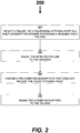
- FIG. 2 illustrates a first example method 200 useful for protecting multi-segment pseudowires.
- a pseudowire element detects a failure of a pseudowire stitching point in the primary pseudowire path
- the failure is signaled to the head-end of the pseudowire.
- failure of a pseudowire stitching point it is meant herein that the failure can be due to the failure of the PSP itself or the failure can be due to failure in the link between the failed PSP and the upstream PSP that detects the failure. That is, if an upstream PSP is unable to communicate with the next downstream PSP, a failure in the downstream PSP is said to be detected.
- each T-PE in a multi-segment pseudowire may serve as both a head-end and a tail-end, depending on which T-PE is the source of the network traffic. That is, the T-PE from which network traffic originates is referred to herein as the head-end of the multi-segment pseudowire with respect to that network traffic and the T-PE that receives network traffic is referred to herein as the tail-end of the multi-segment pseudowire with respect the received network traffic.
- a failure of a pseudowire stitching point in a multi-segment pseudowire is detected. That is, a path failure in a multi-segment pseudowire is detected.
- the detected failure is signaled to the head-end of the multi-segment pseudowire.
- a new path to be used for the pseudowire is chosen for the pseudowire from the at least one backup path that was pre-computed. The backup path does not include the failed stitching point.
- the chosen new path to be used for the pseudowire is signaled to the tail-end of the pseudowire. The signaling of the new path to the tail-end can be conducted along the chosen backup path.
- the tail-end can then also switch to the backup path for traffic flowing in the reverse direction on the multi-segment pseudowire. While the present invention can be utilized with any multi-segment pseudowire, it is especially advantageous when the head-end and tail-end of the pseudowire reside in different domains, such as different autonomous systems.
- Each PSP within the end-to-end path of a given MS-PW is responsible for signaling its ability to act as a stitching point for the pseudowire to head-end/tail-end. This is achieved through the advertisement of reachability for endpoints outside of the local autonomous system.
- reachability information refers to information required for a device to compute a path to reach the destination.
- Layer-2 reachability means packets addressed at one end of the PW with a layer-2 address (commonly known as an Ethernet MAC address) can be forwarded correctly to the far end and received/processed by the switches on that side.
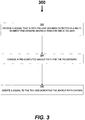
- FIG. 3 illustrates a second example method 300 useful for protecting multi-segment pseudowires.
- the example method 300 of FIG. 3 can be advantageously encoded in logic that is operable to perform the method.
- Such logic can be included in an apparatus that functions as a T-PE for a multi-segment pseudowire.
- such an apparatus can receive a signal that a path failure has been detected in a multi-segment pseudowire having a head-end and a tail-end.
- the apparatus can choose a pre-computed backup path for the pseudowire.
- the received signal includes an indication of a failed pseudowire stitching point and the chosen backup path does not include the failed pseudowire stitching point.
- the apparatus can initiate a signal to the tail-end indicating the backup path chosen.
- the apparatus initiates the signal to the tail-end across the chose backup path.
- the example method 300 of FIG. 3 can be advantageously utilized if the head-end and tail-end reside in different domains, such as different autonomous systems.
- FIG. 4 illustrates a third example method 400 useful for protecting multi-segment pseudowires.
- the example method 400 of FIG. 4 can be advantageously encoded in logic that is operable to perform the method.
- Such logic can be included in an apparatus that functions as a T-PE for a multi-segment pseudowire.
- such an apparatus can compute a primary path from the head-end of a multi-segment pseudowire to the tail-end of the multi-segment pseudowire is computed. This primary path can identify all the pseudowire elements in the path.
- the head-end and tail-end of a MS-PW initiate signaling for PW setup using directed Label Distribution Protocol ("LDP") with a given exit point PSP within their local autonomous system.
- LDP directed Label Distribution Protocol
- the choice of which exit point to use can be based, for example, on Interior Gateway Protocol (“IGP") cost to the exit point or based on a dynamic selection criteria utilizing Path Computation Element Protocol (“PCEP"). It should be noted that the selection of best path also can be obtained using something other than IGP cost, such as Quality of Service (“QoS”), for example.
- QoS Quality of Service
- the result of this signaling is the establishment of a primary path between the T-PEs (i.e., head-end and tail-end) of the MS-PW.
- the PW will utilize an underlying network transport construct to convey packets between the endpoints of the PW.
- the underlying transport construct can be comprised of an MPLS LSP or MPLS Traffic Engineered Tunnel, an L2TPv3 tunnel, or a GRE tunnel, for example.
- Some transport mechanisms, such as TE tunnels inherently are capable of spanning multiple domains, while some transport mechanisms have also been extended to achieve this goal.
- Some additional extensions are being designed such as Path Computation Element (PCE) to enhance these mechanisms which span domains, such as inter-provider boundaries.
- PCE Path Computation Element
- the result of signaling (i.e., setting up) a PW is the establishment of a primary path between the T-PEs (i.e., head-end and tail-end) of the MS-PW.
- a T-PE apparatus In addition to establishing a primary path for the MS-PW, a T-PE apparatus also may establish at least one backup path, which should be used upon failure of the primary path. This is shown in step 420 of FIG. 4 .
- Such backup paths may be established prior to detection of a failure in the primary path. In fact backup paths may be established immediately after the primary path is established.
- a backup path should be a diverse path which takes into account failure of any PSP along the primary path of the MS-PW.
- a T-PE apparatus may function as a Path Computation Client ("PCC") and request a path from a PSP that is functioning as a Path Computation Element ("PCE").
- PCC Path Computation Client
- PCE Path Computation Element
- the PSP may compute a path excluding itself as a stitching point.
- the multi-segment pseudowire can use this computed path in the future when a failure in this PSP is detected. That is, the T-PE may establish a backup path excluding this PSP so that the established backup path can be used later if a failure in this PSP is detected.
- a Path Computation Element is an entity (e.g., component, application, or network node) that is capable of computing a network path or route based on a network graph, and of applying computational constraints during the computation.
- a Path Computation Client is an application requesting a path computation to be performed by a PCE.
- PCEP is a protocol for communications between a PCC and a PCE, or between two PCEs.
- a PCC can request a path from a PCE by sending a PCReq message to the PCE.
- a PCE can reply to a requesting PCC by sending a PCRep message to the PCC.
- a PCRep message can either contain a set of computed path(s) if the request could be satisfied or a negative reply otherwise.
- a new Path Computation Element (“PCE”) communication Protocol (“PCEP”) object may be defined in order for a Path Communication Client (“PCC”) to request a diverse path from an existing multi-domain path along with various path constraints.
- PCE Path Computation Element
- PCEP Path Communication Client
- a PCC may decide to request the exclusion of one or more PSPs based upon the increased path cost due to the diversity constraint. For example, PE1 may request from PSPa (acting as a PCE) to compute a path excluding itself as a stitching point. Conversely, it may request a fully end-to-end diverse path excluding a list of stitching points.
- the head-end i.e., the PCC
- the PCC head-end
- the PCRep message returned to the PCC will only comprise the list of traversed PSPs along with the related cost. Such PSPs' address will then be used by signaling to establish the multi-segment pseudowire.
- more than one PCE may be involved in such computation should the end-to-end path traverse more than 2 domains.
- path segmented diversity should be evaluated by the PCE by performing a Shortest Path First ("SPF") computation on the path (based on IGP cost for example) from each entry PSP to the tail-end.
- SPF Shortest Path First
- a PSP that detects the failure signals the failure to the head-end of the MS-PW.
- PSPa may signal the failure to PE1, telling PE1 to switch to its backup.
- PE1 should ensure that the backup path does not contain the failed element PSPb. Therefore an indication of the failed segment (i.e., the segment between PSPa - PSPb) should be returned by PSPa to PE1.
- PSPb is unable to signal failure of the MS-PW so PE1 sends a "forward explicit" notification to PE2 across the backup path, telling PE2 that the backup path is now in place. PE2 then switches to the backup path.
- network devices may comprise logic configured to perform methods disclosed herein.
- the logic may comprise hardware, such as Attachment Circuitry, for example.
- the logic may also comprise software configured to implement methods disclosed herein.
- Such logic embodied in network devices can be produced without undue experimentation by one of ordinary skill in the art of telecommunications upon review of disclosures made herein.
- a PE may comprise logic configured to 1) function as a head-end of a multi-segment pseudowire; 2) compute a primary path from the head-end to a tail-end of the multi-segment pseudowire; and 3) establish, prior to detection of failure in the primary path, at least one backup path for the multi-segment pseudowire.
- a network comprising a plurality of pseudowire elements forming a multi-segment pseudowire containing a head-end, a tail-end, and a plurality of pseudowire stitching points; may also comprise logic configured to 1) detect a failure of a pseudowire stitching point in the multi-segment pseudowire; 2) signal the detected failure to the head-end; 3) choose a pre-computed backup path; and 4) signal the backup path to the tail-end.
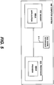
- FIG. 5 illustrates an example computer system architecture for a computer system 540 that performs methods useful in protecting multi-segment pseudowires in accordance with embodiments disclosed herein.
- the computer system 540 may be any type of computerized system such as a personal computer, workstation, portable computing device, mainframe, server or the like.
- the system includes an interconnection mechanism 511 that couples a memory system 512, a processor 513, and a communications interface 514.
- the communications interface 514 allows the computer system 540 to communicate with external devices or systems.
- the memory system 512 may be any type of computer readable medium that is encoded with an application 555-A that represents software code such as data and/or logic instructions (e.g., stored in the memory or on another computer readable medium such as a disk) that embody the processing functionality of embodiments of the invention as explained above.
- the processor 513 can access the memory system 512 via the interconnection mechanism 511 in order to launch, run, execute, interpret or otherwise perform the logic instructions of the application 555-A for the host in order to produce a corresponding process 555-B.
- the process 555-B represents one or more portions of the application 555-A performing within or upon the processor 513 in the computer system.
- examples of the invention include the applications (i.e., the un-executed or non-performing logic instructions and/or data) encoded within a computer readable medium such as a floppy disk, hard disk or in an optical medium, or in a memory type system such as in firmware, read only memory (ROM), or, as in this example, as executable code within the memory system 512 (e.g., within random access memory or RAM).
- a computer readable medium such as a floppy disk, hard disk or in an optical medium
- a memory type system such as in firmware, read only memory (ROM), or, as in this example, as executable code within the memory system 512 (e.g., within random access memory or RAM).
- ROM read only memory
- RAM random access memory
- a computer program product that includes a computer useable medium.
- a computer usable medium can include a readable memory device, such as a hard drive device, a CD-ROM, a DVD-ROM, or a computer diskette, having computer readable program code segments stored thereon.
- the computer readable medium can also include a communications link, either optical, wired, or wireless, having program code segments carried thereon as digital or analog signals.
Claims (9)
- Procédé de protection d'un pseudo-circuit à segments multiples ayant une tête (PE1), une queue (PE2), et un point d'assemblage de pseudo-circuit (PSPa-PSPd) pour connecter des segments de pseudo-circuit, le procédé comprenant de :établir, avant la détection d'une défaillance dans un chemin principal du pseudo-circuit à segments multiples, au moins un chemin de sauvegarde allant de la tête du pseudo-circuit à segments multiples jusqu'à la queue du pseudo-circuit à segments multiples, dans lequel l'établissement du chemin de sauvegarde comprend de :demander, par la tête fonctionnant en tant que client de calcul de chemin, le chemin de sauvegarde à partir du point d'assemblage de pseudo-circuit fonctionnant en tant qu'élément de calcul de chemin; etrecevoir le chemin demandé à partir du point d'assemblage de pseudo-circuit, le chemin demandé étant calculé par le point d'assemblage de pseudo-circuit pour s'exclure lui-même;le procédé comprenant en outre de :détecter une défaillance du point d'assemblage de pseudo-circuit;signaler la défaillance détectée à la tête;choisir le chemin de sauvegarde de pseudo-circuit pré-établi qui n'inclut pas le point d'assemblage défaillant; etsignaler le chemin de sauvegarde de pseudo-circuit choisi à la queue.
- Procédé selon la revendication 1, dans lequel la signalisation est effectuée sur le chemin de sauvegarde de pseudo-circuit choisi.
- Procédé selon la revendication 1, comprenant en outre de signaler le chemin de sauvegarde de pseudo-circuit en envoyant une notification explicite vers l'avant à la queue sur le chemin de sauvegarde de pseudo-circuit.
- Procédé selon la revendication 1, dans lequel la tête réside dans un domaine différent de celui de la queue.
- Procédé selon la revendication 1, dans lequel la tête réside dans un système autonome différent de celui de la queue.
- Support de stockage lisible par ordinateur comprenant un code logiciel conçu, lorsqu'il est exécuté sur un appareil de traitement de données (540), pour :avant de détecter une défaillance dans le chemin principal d'un pseudo-circuit à segments multiples possédant une tête (PE1), une queue (PE2), et un point d'assemblage de pseudo-circuit (PSPa-PSPd) pour connecter des segments de pseudo-circuit, établir au moins un chemin de sauvegarde allant de la tête à la queue du pseudo-circuit à segments multiples, dans lequel l'établissement du chemin de sauvegarde comprend de :demander, par la tête fonctionnant en tant que client de calcul de chemin, le chemin de sauvegarde à partir du point d'assemblage de pseudo-circuit fonctionnant en tant qu'élément de calcul de chemin; etrecevoir le chemin demandé à partir du point d'assemblage de pseudo-circuit, le chemin demandé étant calculé par le point d'assemblage de pseudo-circuit pour s'exclure lui-même;recevoir un signal indiquant une défaillance du point d'assemblage de pseudo-circuit;choisir le chemin de sauvegarde pré-établi pour le pseudo-circuit; etémettre un signal vers la queue indiquant le chemin de sauvegarde choisi.
- Support de stockage lisible par ordinateur selon la revendication 6, dans lequel le signal est envoyé à la queue sur le chemin de sauvegarde choisi.
- Support de stockage lisible par ordinateur selon la revendication 6, dans lequel la tête réside dans un domaine différent de celui de la queue.
- Support de stockage lisible par ordinateur selon la revendication 6, dans lequel la tête réside dans un système autonome différent de celui de la queue.
Applications Claiming Priority (2)
| Application Number | Priority Date | Filing Date | Title |
|---|---|---|---|
| US11/580,167 US8081563B2 (en) | 2006-10-11 | 2006-10-11 | Protecting multi-segment pseudowires |
| PCT/US2007/021232 WO2008045255A2 (fr) | 2006-10-11 | 2007-10-03 | Protection de pseudofils à segments multiples |
Publications (3)
| Publication Number | Publication Date |
|---|---|
| EP2057544A2 EP2057544A2 (fr) | 2009-05-13 |
| EP2057544A4 EP2057544A4 (fr) | 2012-06-27 |
| EP2057544B1 true EP2057544B1 (fr) | 2019-04-17 |
Family
ID=39283354
Family Applications (1)
| Application Number | Title | Priority Date | Filing Date |
|---|---|---|---|
| EP07852511.0A Active EP2057544B1 (fr) | 2006-10-11 | 2007-10-03 | Protection de pseudofils à segments multiples |
Country Status (4)
| Country | Link |
|---|---|
| US (2) | US8081563B2 (fr) |
| EP (1) | EP2057544B1 (fr) |
| CN (1) | CN101523354B (fr) |
| WO (1) | WO2008045255A2 (fr) |
Families Citing this family (39)
| Publication number | Priority date | Publication date | Assignee | Title |
|---|---|---|---|---|
| US7869350B1 (en) | 2003-01-15 | 2011-01-11 | Cisco Technology, Inc. | Method and apparatus for determining a data communication network repair strategy |
| US7330440B1 (en) * | 2003-05-20 | 2008-02-12 | Cisco Technology, Inc. | Method and apparatus for constructing a transition route in a data communications network |
| US7933197B2 (en) * | 2005-02-22 | 2011-04-26 | Cisco Technology, Inc. | Method and apparatus for constructing a repair path around a non-available component in a data communications network |
| US7848224B2 (en) * | 2005-07-05 | 2010-12-07 | Cisco Technology, Inc. | Method and apparatus for constructing a repair path for multicast data |
| US7885179B1 (en) | 2006-03-29 | 2011-02-08 | Cisco Technology, Inc. | Method and apparatus for constructing a repair path around a non-available component in a data communications network |
| US8111616B2 (en) * | 2006-09-08 | 2012-02-07 | Cisco Technology, Inc. | Constructing a repair path in the event of failure of an inter-routing domain system link |
| US8081563B2 (en) | 2006-10-11 | 2011-12-20 | Cisco Technology, Inc. | Protecting multi-segment pseudowires |
| EP2127270B1 (fr) * | 2007-02-26 | 2017-08-02 | Orange | Mécanisme de protection d'un pseudo-lien |
| US8345552B2 (en) * | 2007-02-27 | 2013-01-01 | Alcatel Lucent | Virtual connection route selection apparatus and techniques |
| US20080225864A1 (en) * | 2007-03-16 | 2008-09-18 | Mustapha Aissaoui | Communication network routing apparatus and techniques using logical communication links |
| US7746769B2 (en) * | 2007-03-26 | 2010-06-29 | Alcatel Lucent | Management of redundant and multi-segment pseudo-wire |
| US7940776B2 (en) * | 2007-06-13 | 2011-05-10 | Cisco Technology, Inc. | Fast re-routing in distance vector routing protocol networks |
| US9350639B2 (en) * | 2007-09-06 | 2016-05-24 | Cisco Technology, Inc. | Forwarding data in a data communications network |
| US7940753B2 (en) * | 2007-11-29 | 2011-05-10 | Alcatel Lucent | Enhancing routing optimality in IP networks requiring path establishment |
| CN101483558B (zh) * | 2008-01-10 | 2012-07-04 | 华为技术有限公司 | 网络设备接入分组交换网络的方法、系统及装置 |
| US7668971B2 (en) * | 2008-01-11 | 2010-02-23 | Cisco Technology, Inc. | Dynamic path computation element load balancing with backup path computation elements |
| CN101252461B (zh) * | 2008-04-11 | 2010-08-04 | 华为技术有限公司 | 信令传送的保护方法、装置、终端及系统 |
| WO2009156704A2 (fr) * | 2008-06-27 | 2009-12-30 | France Telecom | Mecanisme de protection d'un circuit virtuel |
| US20100014531A1 (en) * | 2008-07-18 | 2010-01-21 | Alcatel Lucent | Establishing pseudowires in packet switching networks |
| US8351337B2 (en) * | 2008-11-07 | 2013-01-08 | Alcatel Lucent | Tools that facilitate diagnostics for mobile backhaul networks |
| CN101753283B (zh) * | 2008-11-28 | 2014-04-02 | 华为技术有限公司 | 网络业务可靠性的确定方法和装置 |
| US7991016B2 (en) * | 2009-01-06 | 2011-08-02 | Alcatel-Lucent Usa Inc. | High availability clock synchronization and distribution for mobile backhaul networks |
| US8004964B2 (en) * | 2009-03-23 | 2011-08-23 | Cisco Technology, Inc. | Restoring multi-segment pseudowires following failure of a switching PE device |
| US8184528B2 (en) * | 2009-03-30 | 2012-05-22 | Verizon Patent And Licensing Inc. | Network backhaul systems and methods |
| CN102013990B (zh) * | 2009-09-08 | 2014-03-19 | 中兴通讯股份有限公司 | 一种多段伪线故障的端到端通告方法及系统 |
| CN102215143B (zh) * | 2010-04-12 | 2014-10-08 | 华为技术有限公司 | 一种会话故障检测方法和路由设备 |
| US8542578B1 (en) | 2010-08-04 | 2013-09-24 | Cisco Technology, Inc. | System and method for providing a link-state path to a node in a network environment |
| CN102143047B (zh) * | 2010-09-08 | 2014-05-07 | 华为技术有限公司 | 触发路由切换的方法和服务运营商侧运营商边缘设备 |
| US8830826B2 (en) * | 2010-10-15 | 2014-09-09 | Futurewei Technologies, Inc. | System and method for computing a backup egress of a point-to-multi-point label switched path |
| US9143429B2 (en) | 2012-02-28 | 2015-09-22 | Google Inc. | Identifying an egress point to a network location |
| US9225664B2 (en) | 2013-03-15 | 2015-12-29 | Alcatel Lucent | System and method for aggregating pseudowires |
| CN104348719A (zh) | 2013-07-29 | 2015-02-11 | 中兴通讯股份有限公司 | 数据转发处理的方法及设备 |
| US9722916B2 (en) | 2013-09-30 | 2017-08-01 | Cisco Technology, Inc. | Data-plane driven fast protection mechanism for MPLS pseudowire services |
| CN103491103B (zh) * | 2013-09-30 | 2017-01-04 | 福建星网锐捷网络有限公司 | 多段伪线的建立方法和系统及装置 |
| US10063463B2 (en) * | 2014-12-16 | 2018-08-28 | Cisco Technology, Inc. | Node protection for segment routing adjacency segments |
| CN107517160B (zh) * | 2016-06-15 | 2020-08-18 | 阿尔格布鲁控股有限公司 | 一种用于跨不同自治系统进行数据路由的方法、装置及系统 |
| CN108965130B (zh) * | 2018-07-27 | 2021-03-23 | 新华三技术有限公司 | 一种报文转发的方法及装置 |
| US10862743B2 (en) * | 2019-03-18 | 2020-12-08 | Ciena Corporation | Systems and methods to detect, locate, and switch based on signal degrade on multi-segment pseudowires |
| US11425034B1 (en) * | 2021-03-30 | 2022-08-23 | Juniper Networks, Inc. | Determining shielded backup paths |
Family Cites Families (18)
| Publication number | Priority date | Publication date | Assignee | Title |
|---|---|---|---|---|
| US5412376A (en) * | 1990-11-09 | 1995-05-02 | Fujitsu Limited | Method for structuring communications network based on asynchronous transfer mode |
| US7298693B1 (en) * | 1999-10-21 | 2007-11-20 | Tellabs Operations, Inc. | Reverse notification tree for data networks |
| US6917759B2 (en) * | 2002-01-31 | 2005-07-12 | Nortel Networks Limited | Shared mesh signaling algorithm and apparatus |
| CA2388575A1 (fr) * | 2002-05-31 | 2003-11-30 | Alcatel Canada Inc. | Protection de chemin echelonnable pour reseaux mailles |
| US7689693B2 (en) * | 2003-03-31 | 2010-03-30 | Alcatel-Lucent Usa Inc. | Primary/restoration path calculation in mesh networks based on multiple-cost criteria |
| US7558194B2 (en) * | 2003-04-28 | 2009-07-07 | Alcatel-Lucent Usa Inc. | Virtual private network fault tolerance |
| US7343423B2 (en) * | 2003-10-07 | 2008-03-11 | Cisco Technology, Inc. | Enhanced switchover for MPLS fast reroute |
| US8218569B2 (en) * | 2004-04-05 | 2012-07-10 | Verizon Business Global Llc | Apparatus and method for terminating service emulation instances |
| US7643409B2 (en) * | 2004-08-25 | 2010-01-05 | Cisco Technology, Inc. | Computer network with point-to-point pseudowire redundancy |
| US7516224B2 (en) * | 2004-10-21 | 2009-04-07 | Cisco Technology, Inc. | Pseudowire termination directly on a router |
| US7512063B2 (en) * | 2004-12-14 | 2009-03-31 | Cisco Technology, Inc. | Border router protection with backup tunnel stitching in a computer network |
| US7515529B2 (en) * | 2004-12-14 | 2009-04-07 | Cisco Technology, Inc. | Efficient mechanism for fast recovery in case of border router node failure in a computer network |
| US20060133265A1 (en) | 2004-12-22 | 2006-06-22 | Alcatel | Virtual private networking methods and systems |
| US7782841B2 (en) * | 2005-01-05 | 2010-08-24 | Cisco Technology, Inc. | Method and system for transporting data using pseudowire circuits over a bridged network |
| US8045492B2 (en) * | 2005-01-20 | 2011-10-25 | Nortel Networks Limited | Dynamic establishment of virtual circuits using multi-segment pseudowires |
| US7852748B2 (en) * | 2005-03-23 | 2010-12-14 | Cisco Technology, Inc. | Method and system for providing voice QoS during network failure |
| EP1917779B1 (fr) * | 2005-08-26 | 2012-02-22 | Nortel Networks Limited | Procede d'etablissement d'un pseudo-fil multisegment au niveau de domaines ayant des protocoles de signalisation de pseudo-fil differents |
| US8081563B2 (en) | 2006-10-11 | 2011-12-20 | Cisco Technology, Inc. | Protecting multi-segment pseudowires |
-
2006
- 2006-10-11 US US11/580,167 patent/US8081563B2/en active Active
-
2007
- 2007-10-03 WO PCT/US2007/021232 patent/WO2008045255A2/fr active Application Filing
- 2007-10-03 EP EP07852511.0A patent/EP2057544B1/fr active Active
- 2007-10-03 CN CN200780038091.6A patent/CN101523354B/zh active Active
-
2011
- 2011-12-09 US US13/315,948 patent/US8804496B2/en not_active Expired - Fee Related
Non-Patent Citations (2)
| Title |
|---|
| HIMANSHU SHAH CIENA CORP MATTHEW BOCCI MUSTAPHA AISSAOUI JASON RUSMISEL ALCATEL YETIK SERBEST SBC NABIL BITAR VERIZON: "Multi-Segment Pseudo Wire Signaling; draft-shah-bocci-pwe3-ms-pw-signaling-00.txt", MULTI-SEGMENT PSEUDO WIRE SIGNALING; DRAFT-SHAH-BOCCI-PWE3-MS-PW-SIGNALING-00.TXT, INTERNET ENGINEERING TASK FORCE, IETF; STANDARDWORKINGDRAFT, INTERNET SOCIETY (ISOC) 4, RUE DES FALAISES CH- 1205 GENEVA, SWITZERLAND, 1 June 2005 (2005-06-01), XP015040129 * |
| PING PAN (HAMMERHEAD SYSTEMS): "Pseudo Wire Protection; draft-pan-pwe3-protection-01.txt", PSEUDO WIRE PROTECTION; DRAFT-PAN-PWE3-PROTECTION-01.TXT, INTERNET ENGINEERING TASK FORCE, IETF; STANDARDWORKINGDRAFT, INTERNET SOCIETY (ISOC) 4, RUE DES FALAISES CH- 1205 GENEVA, SWITZERLAND, no. 1, 1 July 2005 (2005-07-01), XP015040259 * |
Also Published As
| Publication number | Publication date |
|---|---|
| US20120082025A1 (en) | 2012-04-05 |
| CN101523354B (zh) | 2014-06-11 |
| CN101523354A (zh) | 2009-09-02 |
| WO2008045255A3 (fr) | 2008-06-26 |
| US20080089227A1 (en) | 2008-04-17 |
| US8804496B2 (en) | 2014-08-12 |
| EP2057544A4 (fr) | 2012-06-27 |
| US8081563B2 (en) | 2011-12-20 |
| WO2008045255A2 (fr) | 2008-04-17 |
| EP2057544A2 (fr) | 2009-05-13 |
Similar Documents
| Publication | Publication Date | Title |
|---|---|---|
| EP2057544B1 (fr) | Protection de pseudofils à segments multiples | |
| US10721158B2 (en) | Technique for determining whether to reestablish fast rerouted primary tunnels based on backup tunnel path quality feedback | |
| US7710902B2 (en) | Path diversity for customer-to-customer traffic | |
| US7920466B2 (en) | Protection of hierarchical tunnel head-end nodes | |
| KR101685855B1 (ko) | 인터 도메인 te lsp에서 ero 확장 실패에 대해 신호하고 응답하는 시스템, 방법 및 장치 | |
| KR101354467B1 (ko) | 패킷 스위칭된 제공자 네트워크를 통한 클라이언트 데이터 전송을 위한 방법 | |
| US7733883B2 (en) | Method for implementing a virtual leased line | |
| US7765306B2 (en) | Technique for enabling bidirectional forwarding detection between edge devices in a computer network | |
| Raj et al. | A survey of IP and multiprotocol label switching fast reroute schemes | |
| US8576708B2 (en) | System and method for link protection using shared SRLG association | |
| US8837521B2 (en) | Ethernet network within MPLS network | |
| WO2012116545A1 (fr) | Réseau privé virtuel (vpn) à commutation d'étiquettes multiprotocole (mpls) sur un réseau fédérateur ethernet routé | |
| US20090292942A1 (en) | Techniques for determining optimized local repair paths | |
| US9215136B2 (en) | Aggregated delivery of tunnel fault messages on common ethernet segments | |
| WO2007047867A9 (fr) | Construction et mise en oeuvre de pistes de sauvegarde dans des systemes autonomes | |
| Pelsser et al. | Extending RSVP-TE to support inter-AS LSPs | |
| Das et al. | A method of designing a path restoration scheme for MPLS based network | |
| Autenrieth et al. | Components of MPLS recovery supporting differentiated resilience requirements | |
| Atlas et al. | IP Fast Reroute Overview and Things we are struggling to solve | |
| Singh | Protection and Restoration in MPLS based Networks | |
| Aron | Design of MPLS networks VPN and TE with testing its resiliency and reliability | |
| Liu et al. | Internet Engineering Task Force H. Chen Internet-Draft Huawei Technologies Intended status: Standards Track N. So Expires: January 17, 2013 Tata Communications |
Legal Events
| Date | Code | Title | Description |
|---|---|---|---|
| PUAI | Public reference made under article 153(3) epc to a published international application that has entered the european phase |
Free format text: ORIGINAL CODE: 0009012 |
|
| 17P | Request for examination filed |
Effective date: 20090330 |
|
| AK | Designated contracting states |
Kind code of ref document: A2 Designated state(s): AT BE BG CH CY CZ DE DK EE ES FI FR GB GR HU IE IS IT LI LT LU LV MC MT NL PL PT RO SE SI SK TR |
|
| AX | Request for extension of the european patent |
Extension state: AL BA HR MK RS |
|
| DAX | Request for extension of the european patent (deleted) | ||
| A4 | Supplementary search report drawn up and despatched |
Effective date: 20120531 |
|
| RIC1 | Information provided on ipc code assigned before grant |
Ipc: H04L 12/56 20060101AFI20120524BHEP |
|
| STAA | Information on the status of an ep patent application or granted ep patent |
Free format text: STATUS: EXAMINATION IS IN PROGRESS |
|
| 17Q | First examination report despatched |
Effective date: 20170612 |
|
| REG | Reference to a national code |
Ref country code: DE Ref legal event code: R079 Ref document number: 602007058149 Country of ref document: DE Free format text: PREVIOUS MAIN CLASS: G06F0011000000 Ipc: H04L0012721000 |
|
| GRAP | Despatch of communication of intention to grant a patent |
Free format text: ORIGINAL CODE: EPIDOSNIGR1 |
|
| STAA | Information on the status of an ep patent application or granted ep patent |
Free format text: STATUS: GRANT OF PATENT IS INTENDED |
|
| RIC1 | Information provided on ipc code assigned before grant |
Ipc: H04L 12/721 20090513AFI20181010BHEP Ipc: H04L 12/723 20090513ALI20181010BHEP Ipc: H04L 12/707 20090513ALI20181010BHEP Ipc: H04L 12/703 20090513ALI20181010BHEP Ipc: H04L 1/22 20060101ALI20181010BHEP Ipc: H04L 12/715 20090513ALI20181010BHEP Ipc: H04L 12/717 20090513ALI20181010BHEP |
|
| INTG | Intention to grant announced |
Effective date: 20181109 |
|
| RIC1 | Information provided on ipc code assigned before grant |
Ipc: H04L 12/717 20130101ALI20181010BHEP Ipc: H04L 12/707 20130101ALI20181010BHEP Ipc: H04L 12/703 20130101ALI20181010BHEP Ipc: H04L 1/22 20060101ALI20181010BHEP Ipc: H04L 12/721 20130101AFI20181010BHEP Ipc: H04L 12/715 20130101ALI20181010BHEP Ipc: H04L 12/723 20130101ALI20181010BHEP |
|
| RIC1 | Information provided on ipc code assigned before grant |
Ipc: H04L 12/715 20130101ALI20181010BHEP Ipc: H04L 1/22 20060101ALI20181010BHEP Ipc: H04L 12/703 20130101ALI20181010BHEP Ipc: H04L 12/707 20130101ALI20181010BHEP Ipc: H04L 12/717 20130101ALI20181010BHEP Ipc: H04L 12/721 20130101AFI20181010BHEP Ipc: H04L 12/723 20130101ALI20181010BHEP |
|
| GRAS | Grant fee paid |
Free format text: ORIGINAL CODE: EPIDOSNIGR3 |
|
| GRAA | (expected) grant |
Free format text: ORIGINAL CODE: 0009210 |
|
| STAA | Information on the status of an ep patent application or granted ep patent |
Free format text: STATUS: THE PATENT HAS BEEN GRANTED |
|
| AK | Designated contracting states |
Kind code of ref document: B1 Designated state(s): AT BE BG CH CY CZ DE DK EE ES FI FR GB GR HU IE IS IT LI LT LU LV MC MT NL PL PT RO SE SI SK TR |
|
| REG | Reference to a national code |
Ref country code: GB Ref legal event code: FG4D |
|
| REG | Reference to a national code |
Ref country code: CH Ref legal event code: EP |
|
| REG | Reference to a national code |
Ref country code: DE Ref legal event code: R096 Ref document number: 602007058149 Country of ref document: DE |
|
| REG | Reference to a national code |
Ref country code: AT Ref legal event code: REF Ref document number: 1122758 Country of ref document: AT Kind code of ref document: T Effective date: 20190515 Ref country code: IE Ref legal event code: FG4D |
|
| REG | Reference to a national code |
Ref country code: NL Ref legal event code: MP Effective date: 20190417 |
|
| REG | Reference to a national code |
Ref country code: LT Ref legal event code: MG4D |
|
| PG25 | Lapsed in a contracting state [announced via postgrant information from national office to epo] |
Ref country code: NL Free format text: LAPSE BECAUSE OF FAILURE TO SUBMIT A TRANSLATION OF THE DESCRIPTION OR TO PAY THE FEE WITHIN THE PRESCRIBED TIME-LIMIT Effective date: 20190417 |
|
| PG25 | Lapsed in a contracting state [announced via postgrant information from national office to epo] |
Ref country code: PT Free format text: LAPSE BECAUSE OF FAILURE TO SUBMIT A TRANSLATION OF THE DESCRIPTION OR TO PAY THE FEE WITHIN THE PRESCRIBED TIME-LIMIT Effective date: 20190819 Ref country code: LT Free format text: LAPSE BECAUSE OF FAILURE TO SUBMIT A TRANSLATION OF THE DESCRIPTION OR TO PAY THE FEE WITHIN THE PRESCRIBED TIME-LIMIT Effective date: 20190417 Ref country code: FI Free format text: LAPSE BECAUSE OF FAILURE TO SUBMIT A TRANSLATION OF THE DESCRIPTION OR TO PAY THE FEE WITHIN THE PRESCRIBED TIME-LIMIT Effective date: 20190417 Ref country code: SE Free format text: LAPSE BECAUSE OF FAILURE TO SUBMIT A TRANSLATION OF THE DESCRIPTION OR TO PAY THE FEE WITHIN THE PRESCRIBED TIME-LIMIT Effective date: 20190417 Ref country code: ES Free format text: LAPSE BECAUSE OF FAILURE TO SUBMIT A TRANSLATION OF THE DESCRIPTION OR TO PAY THE FEE WITHIN THE PRESCRIBED TIME-LIMIT Effective date: 20190417 |
|
| PG25 | Lapsed in a contracting state [announced via postgrant information from national office to epo] |
Ref country code: GR Free format text: LAPSE BECAUSE OF FAILURE TO SUBMIT A TRANSLATION OF THE DESCRIPTION OR TO PAY THE FEE WITHIN THE PRESCRIBED TIME-LIMIT Effective date: 20190718 Ref country code: BG Free format text: LAPSE BECAUSE OF FAILURE TO SUBMIT A TRANSLATION OF THE DESCRIPTION OR TO PAY THE FEE WITHIN THE PRESCRIBED TIME-LIMIT Effective date: 20190717 Ref country code: LV Free format text: LAPSE BECAUSE OF FAILURE TO SUBMIT A TRANSLATION OF THE DESCRIPTION OR TO PAY THE FEE WITHIN THE PRESCRIBED TIME-LIMIT Effective date: 20190417 Ref country code: PL Free format text: LAPSE BECAUSE OF FAILURE TO SUBMIT A TRANSLATION OF THE DESCRIPTION OR TO PAY THE FEE WITHIN THE PRESCRIBED TIME-LIMIT Effective date: 20190417 |
|
| REG | Reference to a national code |
Ref country code: AT Ref legal event code: MK05 Ref document number: 1122758 Country of ref document: AT Kind code of ref document: T Effective date: 20190417 |
|
| PG25 | Lapsed in a contracting state [announced via postgrant information from national office to epo] |
Ref country code: IS Free format text: LAPSE BECAUSE OF FAILURE TO SUBMIT A TRANSLATION OF THE DESCRIPTION OR TO PAY THE FEE WITHIN THE PRESCRIBED TIME-LIMIT Effective date: 20190817 |
|
| REG | Reference to a national code |
Ref country code: DE Ref legal event code: R097 Ref document number: 602007058149 Country of ref document: DE |
|
| PG25 | Lapsed in a contracting state [announced via postgrant information from national office to epo] |
Ref country code: EE Free format text: LAPSE BECAUSE OF FAILURE TO SUBMIT A TRANSLATION OF THE DESCRIPTION OR TO PAY THE FEE WITHIN THE PRESCRIBED TIME-LIMIT Effective date: 20190417 Ref country code: DK Free format text: LAPSE BECAUSE OF FAILURE TO SUBMIT A TRANSLATION OF THE DESCRIPTION OR TO PAY THE FEE WITHIN THE PRESCRIBED TIME-LIMIT Effective date: 20190417 Ref country code: SK Free format text: LAPSE BECAUSE OF FAILURE TO SUBMIT A TRANSLATION OF THE DESCRIPTION OR TO PAY THE FEE WITHIN THE PRESCRIBED TIME-LIMIT Effective date: 20190417 Ref country code: AT Free format text: LAPSE BECAUSE OF FAILURE TO SUBMIT A TRANSLATION OF THE DESCRIPTION OR TO PAY THE FEE WITHIN THE PRESCRIBED TIME-LIMIT Effective date: 20190417 Ref country code: RO Free format text: LAPSE BECAUSE OF FAILURE TO SUBMIT A TRANSLATION OF THE DESCRIPTION OR TO PAY THE FEE WITHIN THE PRESCRIBED TIME-LIMIT Effective date: 20190417 Ref country code: CZ Free format text: LAPSE BECAUSE OF FAILURE TO SUBMIT A TRANSLATION OF THE DESCRIPTION OR TO PAY THE FEE WITHIN THE PRESCRIBED TIME-LIMIT Effective date: 20190417 |
|
| PLBE | No opposition filed within time limit |
Free format text: ORIGINAL CODE: 0009261 |
|
| STAA | Information on the status of an ep patent application or granted ep patent |
Free format text: STATUS: NO OPPOSITION FILED WITHIN TIME LIMIT |
|
| PG25 | Lapsed in a contracting state [announced via postgrant information from national office to epo] |
Ref country code: IT Free format text: LAPSE BECAUSE OF FAILURE TO SUBMIT A TRANSLATION OF THE DESCRIPTION OR TO PAY THE FEE WITHIN THE PRESCRIBED TIME-LIMIT Effective date: 20190417 |
|
| 26N | No opposition filed |
Effective date: 20200120 |
|
| PG25 | Lapsed in a contracting state [announced via postgrant information from national office to epo] |
Ref country code: TR Free format text: LAPSE BECAUSE OF FAILURE TO SUBMIT A TRANSLATION OF THE DESCRIPTION OR TO PAY THE FEE WITHIN THE PRESCRIBED TIME-LIMIT Effective date: 20190417 |
|
| PG25 | Lapsed in a contracting state [announced via postgrant information from national office to epo] |
Ref country code: MC Free format text: LAPSE BECAUSE OF FAILURE TO SUBMIT A TRANSLATION OF THE DESCRIPTION OR TO PAY THE FEE WITHIN THE PRESCRIBED TIME-LIMIT Effective date: 20190417 Ref country code: SI Free format text: LAPSE BECAUSE OF FAILURE TO SUBMIT A TRANSLATION OF THE DESCRIPTION OR TO PAY THE FEE WITHIN THE PRESCRIBED TIME-LIMIT Effective date: 20190417 |
|
| REG | Reference to a national code |
Ref country code: CH Ref legal event code: PL |
|
| PG25 | Lapsed in a contracting state [announced via postgrant information from national office to epo] |
Ref country code: CH Free format text: LAPSE BECAUSE OF NON-PAYMENT OF DUE FEES Effective date: 20191031 Ref country code: LU Free format text: LAPSE BECAUSE OF NON-PAYMENT OF DUE FEES Effective date: 20191003 Ref country code: LI Free format text: LAPSE BECAUSE OF NON-PAYMENT OF DUE FEES Effective date: 20191031 |
|
| REG | Reference to a national code |
Ref country code: BE Ref legal event code: MM Effective date: 20191031 |
|
| PG25 | Lapsed in a contracting state [announced via postgrant information from national office to epo] |
Ref country code: BE Free format text: LAPSE BECAUSE OF NON-PAYMENT OF DUE FEES Effective date: 20191031 |
|
| PG25 | Lapsed in a contracting state [announced via postgrant information from national office to epo] |
Ref country code: IE Free format text: LAPSE BECAUSE OF NON-PAYMENT OF DUE FEES Effective date: 20191003 |
|
| PG25 | Lapsed in a contracting state [announced via postgrant information from national office to epo] |
Ref country code: CY Free format text: LAPSE BECAUSE OF FAILURE TO SUBMIT A TRANSLATION OF THE DESCRIPTION OR TO PAY THE FEE WITHIN THE PRESCRIBED TIME-LIMIT Effective date: 20190417 |
|
| PG25 | Lapsed in a contracting state [announced via postgrant information from national office to epo] |
Ref country code: HU Free format text: LAPSE BECAUSE OF FAILURE TO SUBMIT A TRANSLATION OF THE DESCRIPTION OR TO PAY THE FEE WITHIN THE PRESCRIBED TIME-LIMIT; INVALID AB INITIO Effective date: 20071003 Ref country code: MT Free format text: LAPSE BECAUSE OF FAILURE TO SUBMIT A TRANSLATION OF THE DESCRIPTION OR TO PAY THE FEE WITHIN THE PRESCRIBED TIME-LIMIT Effective date: 20190417 |
|
| REG | Reference to a national code |
Ref country code: DE Ref legal event code: R079 Ref document number: 602007058149 Country of ref document: DE Free format text: PREVIOUS MAIN CLASS: H04L0012721000 Ipc: H04L0045000000 |
|
| PGFP | Annual fee paid to national office [announced via postgrant information from national office to epo] |
Ref country code: GB Payment date: 20231027 Year of fee payment: 17 |
|
| PGFP | Annual fee paid to national office [announced via postgrant information from national office to epo] |
Ref country code: FR Payment date: 20231027 Year of fee payment: 17 Ref country code: DE Payment date: 20231026 Year of fee payment: 17 |