EP2056445A2 - Electric motor control with buck boost convertor - Google Patents
Electric motor control with buck boost convertor Download PDFInfo
- Publication number
- EP2056445A2 EP2056445A2 EP08252874A EP08252874A EP2056445A2 EP 2056445 A2 EP2056445 A2 EP 2056445A2 EP 08252874 A EP08252874 A EP 08252874A EP 08252874 A EP08252874 A EP 08252874A EP 2056445 A2 EP2056445 A2 EP 2056445A2
- Authority
- EP
- European Patent Office
- Prior art keywords
- converter
- motor
- power supply
- electric motor
- motor housing
- Prior art date
- Legal status (The legal status is an assumption and is not a legal conclusion. Google has not performed a legal analysis and makes no representation as to the accuracy of the status listed.)
- Granted
Links
Images

Classifications
-
- H—ELECTRICITY
- H02—GENERATION; CONVERSION OR DISTRIBUTION OF ELECTRIC POWER
- H02K—DYNAMO-ELECTRIC MACHINES
- H02K11/00—Structural association of dynamo-electric machines with electric components or with devices for shielding, monitoring or protection
- H02K11/0094—Structural association with other electrical or electronic devices
-
- H—ELECTRICITY
- H02—GENERATION; CONVERSION OR DISTRIBUTION OF ELECTRIC POWER
- H02K—DYNAMO-ELECTRIC MACHINES
- H02K9/00—Arrangements for cooling or ventilating
- H02K9/02—Arrangements for cooling or ventilating by ambient air flowing through the machine
- H02K9/04—Arrangements for cooling or ventilating by ambient air flowing through the machine having means for generating a flow of cooling medium
- H02K9/06—Arrangements for cooling or ventilating by ambient air flowing through the machine having means for generating a flow of cooling medium with fans or impellers driven by the machine shaft
-
- H—ELECTRICITY
- H02—GENERATION; CONVERSION OR DISTRIBUTION OF ELECTRIC POWER
- H02P—CONTROL OR REGULATION OF ELECTRIC MOTORS, ELECTRIC GENERATORS OR DYNAMO-ELECTRIC CONVERTERS; CONTROLLING TRANSFORMERS, REACTORS OR CHOKE COILS
- H02P25/00—Arrangements or methods for the control of AC motors characterised by the kind of AC motor or by structural details
- H02P25/02—Arrangements or methods for the control of AC motors characterised by the kind of AC motor or by structural details characterised by the kind of motor
- H02P25/022—Synchronous motors
- H02P25/024—Synchronous motors controlled by supply frequency
-
- H—ELECTRICITY
- H02—GENERATION; CONVERSION OR DISTRIBUTION OF ELECTRIC POWER
- H02P—CONTROL OR REGULATION OF ELECTRIC MOTORS, ELECTRIC GENERATORS OR DYNAMO-ELECTRIC CONVERTERS; CONTROLLING TRANSFORMERS, REACTORS OR CHOKE COILS
- H02P25/00—Arrangements or methods for the control of AC motors characterised by the kind of AC motor or by structural details
- H02P25/16—Arrangements or methods for the control of AC motors characterised by the kind of AC motor or by structural details characterised by the circuit arrangement or by the kind of wiring
- H02P25/22—Multiple windings; Windings for more than three phases
-
- H—ELECTRICITY
- H02—GENERATION; CONVERSION OR DISTRIBUTION OF ELECTRIC POWER
- H02P—CONTROL OR REGULATION OF ELECTRIC MOTORS, ELECTRIC GENERATORS OR DYNAMO-ELECTRIC CONVERTERS; CONTROLLING TRANSFORMERS, REACTORS OR CHOKE COILS
- H02P27/00—Arrangements or methods for the control of AC motors characterised by the kind of supply voltage
- H02P27/04—Arrangements or methods for the control of AC motors characterised by the kind of supply voltage using variable-frequency supply voltage, e.g. inverter or converter supply voltage
- H02P27/06—Arrangements or methods for the control of AC motors characterised by the kind of supply voltage using variable-frequency supply voltage, e.g. inverter or converter supply voltage using DC to AC converters or inverters
-
- H—ELECTRICITY
- H02—GENERATION; CONVERSION OR DISTRIBUTION OF ELECTRIC POWER
- H02M—APPARATUS FOR CONVERSION BETWEEN AC AND AC, BETWEEN AC AND DC, OR BETWEEN DC AND DC, AND FOR USE WITH MAINS OR SIMILAR POWER SUPPLY SYSTEMS; CONVERSION OF DC OR AC INPUT POWER INTO SURGE OUTPUT POWER; CONTROL OR REGULATION THEREOF
- H02M1/00—Details of apparatus for conversion
- H02M1/0067—Converter structures employing plural converter units, other than for parallel operation of the units on a single load
- H02M1/008—Plural converter units for generating at two or more independent and non-parallel outputs, e.g. systems with plural point of load switching regulators
-
- H—ELECTRICITY
- H02—GENERATION; CONVERSION OR DISTRIBUTION OF ELECTRIC POWER
- H02P—CONTROL OR REGULATION OF ELECTRIC MOTORS, ELECTRIC GENERATORS OR DYNAMO-ELECTRIC CONVERTERS; CONTROLLING TRANSFORMERS, REACTORS OR CHOKE COILS
- H02P2201/00—Indexing scheme relating to controlling arrangements characterised by the converter used
- H02P2201/07—DC-DC step-up or step-down converter inserted between the power supply and the inverter supplying the motor, e.g. to control voltage source fluctuations, to vary the motor speed
Definitions
- This application relates to a voltage supply for an electric motor.
- a voltage supply for an electric motor is directed into a converter for changing the voltage that is ultimately supplied to an inverter, and then to stator windings of the electric motor.
- electric motors with this basic architecture have utilized a buck converter, which is operable to lower the voltage when desired.
- the buck converter is operable to decrease the voltage, thus providing more efficient operation of the motor.
- a feature of prior motor architectures is that the converter would typically be provided with a control or inductor coil. This coil often becomes quite hot during operation, and cooling systems for the converter thus must be relatively robust in large part to cool the coil.
- inductors that have been part of various controls have been positioned within a motor housing for cooling (see, e.g. EP 1860756 ), such inductors have not been part of a voltage converter that is positioned outside of the motor housing.
- a buck boost converter is associated with an inverter for supplying power to an electric motor.
- a control coil for the converter extends away from the converter and into an interior housing of the electric motor, such that a thermal management system for cooling the electric motor can also cool the inductor.
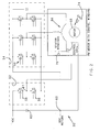
- FIG. 1 An electric motor and power supply 20 are illustrated in Figure 1 .
- a voltage supply is associated with a capacitor 23, and a voltage converter 22.
- the voltage converter 22 includes switches 24, 26, 28 and 30.
- An inverter 32 having a plurality of switches 34 is positioned downstream of the converter 22.
- the inverter directs voltage into the stator windings 36 which are operable to drive the rotor 38.
- the windings 36 and rotor 38 are mounted within a motor housing 40.
- a thermal management system for the motor such as a fan 42, directs cooling fluid over the rotor 38 and the stator 36. While a fan moving air is illustrated, other ways of directing a cooling fluid within the housing 40 are known, and would come within the scope of this invention.
- a control coil or inductor 44 is connected at 45 and 47 into the converter 22.
- the control coil 44 extends away from the converter 22, and within the housing 40 such that it can be cooled by the cooling fluid utilized to cool the motor elements.
- the converter itself, other than the control coil, is mounted outside the motor housing.
- the converter 22 is a buck boost converter.
- the converter 22 has switch 28 closed and switch 30 opened at low speeds. At higher speeds, switch 26 is closed and switch 24 is opened, with switch 28 closed and switch 30 providing a boost, or voltage increase, function.
- switches 26 and 28 are opened and switches 24 and 30 are closed.
- FIG. 2 an alternative voltage supply circuit 50 is illustrated. Again, capacitor 60 is positioned upstream of a converter 52.
- the inverter 54 includes a plurality of switches 64 supplying voltage to the stator windings 66 for driving the rotor 68.
- the coil 72 extends within the housing 70 and is cooled by the thermal management system 74. The coil 72 is connected at 61 and 62.
- the converter 52 includes switches 56 and 58.
- a duty cycle of the voltage supplied is utilized to provide a buck boost output voltage.
- Switch 56 is opened, and switch 58 provides the buck boost function. During the failure mode, the switch 58 is opened and switch 56 is closed.
- the operation of the buck boost converters 22 and 52 as shown in Figures 1 and 2 may be generally as known in the art. Moreover, any number of other arrangements can be utilized to provide the buck boost function. It is not the structure of any one buck boost converter which is inventive in this application, but rather the use of a buck boost converter associated with an inverter and an electric motor. Moreover, the position of the control coil within the housing is also novel.
Landscapes
- Engineering & Computer Science (AREA)
- Power Engineering (AREA)
- Dc-Dc Converters (AREA)
- Motor Or Generator Cooling System (AREA)
- Inverter Devices (AREA)
Abstract
Description
- This application relates to a voltage supply for an electric motor.
- Typically, a voltage supply for an electric motor is directed into a converter for changing the voltage that is ultimately supplied to an inverter, and then to stator windings of the electric motor.
- In the past, electric motors with this basic architecture have utilized a buck converter, which is operable to lower the voltage when desired. As an example, when operating at a low speed, the buck converter is operable to decrease the voltage, thus providing more efficient operation of the motor.
- A feature of prior motor architectures is that the converter would typically be provided with a control or inductor coil. This coil often becomes quite hot during operation, and cooling systems for the converter thus must be relatively robust in large part to cool the coil.
- While inductors that have been part of various controls have been positioned within a motor housing for cooling (see, e.g.
EP 1860756 ), such inductors have not been part of a voltage converter that is positioned outside of the motor housing. - While buck boost converters which can both increase and decrease voltage are known, they have not been provided into an electric motor voltage supply.
- In disclosed embodiments of this invention, a buck boost converter is associated with an inverter for supplying power to an electric motor. In a separate feature, a control coil for the converter extends away from the converter and into an interior housing of the electric motor, such that a thermal management system for cooling the electric motor can also cool the inductor.
- These and other features of the present invention can be best understood from the following specification and drawings, the following of which is a brief description.
-
-
Figure 1 shows a first schematic power supply circuit of the present invention. -
Figure 2 shows a second schematic power supply circuit. - An electric motor and
power supply 20 are illustrated inFigure 1 . A voltage supply is associated with acapacitor 23, and avoltage converter 22. Thevoltage converter 22 includesswitches inverter 32 having a plurality ofswitches 34 is positioned downstream of theconverter 22. The inverter directs voltage into thestator windings 36 which are operable to drive therotor 38. Thewindings 36 androtor 38 are mounted within amotor housing 40. As known, a thermal management system for the motor, such as afan 42, directs cooling fluid over therotor 38 and thestator 36. While a fan moving air is illustrated, other ways of directing a cooling fluid within thehousing 40 are known, and would come within the scope of this invention. - A control coil or
inductor 44 is connected at 45 and 47 into theconverter 22. Thecontrol coil 44 extends away from theconverter 22, and within thehousing 40 such that it can be cooled by the cooling fluid utilized to cool the motor elements. The converter itself, other than the control coil, is mounted outside the motor housing. - In operation, the
converter 22 is a buck boost converter. Theconverter 22 has switch 28 closed and switch 30 opened at low speeds. At higher speeds,switch 26 is closed andswitch 24 is opened, withswitch 28 closed and switch 30 providing a boost, or voltage increase, function. - During failure mode, the
switches - In
Figure 2 , an alternativevoltage supply circuit 50 is illustrated. Again,capacitor 60 is positioned upstream of aconverter 52. Theinverter 54 includes a plurality ofswitches 64 supplying voltage to thestator windings 66 for driving therotor 68. The coil 72 extends within thehousing 70 and is cooled by thethermal management system 74. The coil 72 is connected at 61 and 62. Theconverter 52 includesswitches 
with D being the duty cycle and Vn the input voltage.Switch 56 is opened, andswitch 58 provides the buck boost function. During the failure mode, theswitch 58 is opened andswitch 56 is closed. - The operation of the
buck boost converters Figures 1 and2 may be generally as known in the art. Moreover, any number of other arrangements can be utilized to provide the buck boost function. It is not the structure of any one buck boost converter which is inventive in this application, but rather the use of a buck boost converter associated with an inverter and an electric motor. Moreover, the position of the control coil within the housing is also novel. - While permanent magnet motors are illustrated, the invention would extend to all types of motors. One particular motor that may be utilized with this invention is disclosed in
U.S. Patent 7,262,539 . - Although an embodiment of this invention has been disclosed, a worker of ordinary skill in this art would recognize that certain modifications would come within the scope of this invention. For that reason, the following claims should be studied to determine the true scope and content of this invention.
Claims (8)
- An electric motor and power supply (20; 50) comprising:a motor rotor (38; 68) and stator windings (36; 66) within a motor housing (40; 70);a converter (22; 52) operable to receive an input voltage, and increase and decrease input voltage as desired; andan inverter (32; 54) positioned between said converter and said stator windings.
- The power supply as set forth in Claim 1, wherein said converter (22; 52) includes two switches (24, 26, 28, 30; 56, 58), and a duty cycle of the input voltage is utilized to increase or decrease the voltage.
- The power supply as set forth in Claim 1 or 2, wherein said converter (22) includes two pairs of switches (24, 26, 28, 30), and the increase or decrease in the input voltage is achieved by selectively opening and closing said two pairs of switches.
- The power supply as set forth in Claim 1, 2 or 3, wherein a control coil (44; 72) is associated with said converter (22; 52), and said control coil being positioned within said motor housing (40; 70), and a thermal management system (42; 74) for the motor moving a fluid within said motor housing to cool the electric motor and control coil.
- The power supply as set forth in Claim 4, wherein a fluid moving member (42; 74) positively moves the fluid within the motor housing.
- An electric motor and power supply (20; 50) comprising:a motor rotor (38; 68) and stator windings (36; 66) within a motor housing (40; 70);a converter (22; 52) operable to receive an input voltage, and change the input voltage as desired;an inverter (32; 54) positioned between said converter and said stator windings; anda control coil (44; 72) in said converter, said control coil extending from said converter into said motor housing.
- The power supply as set forth in Claim 6, wherein a thermal management system (42; 74) for the motor is provided for moving a fluid within said motor housing to cool the electric motor and the control coil.
- The power supply as set forth in Claim 7, wherein a fluid moving member (42; 74) positively moves the fluid within the motor housing.
Applications Claiming Priority (1)
| Application Number | Priority Date | Filing Date | Title |
|---|---|---|---|
| US11/934,170 US8217616B2 (en) | 2007-11-02 | 2007-11-02 | Electric motor control with buck boost converter |
Publications (3)
| Publication Number | Publication Date |
|---|---|
| EP2056445A2 true EP2056445A2 (en) | 2009-05-06 |
| EP2056445A3 EP2056445A3 (en) | 2012-08-29 |
| EP2056445B1 EP2056445B1 (en) | 2018-05-30 |
Family
ID=40383831
Family Applications (1)
| Application Number | Title | Priority Date | Filing Date |
|---|---|---|---|
| EP08252874.6A Ceased EP2056445B1 (en) | 2007-11-02 | 2008-08-29 | Electric motor control with buck boost convertor |
Country Status (2)
| Country | Link |
|---|---|
| US (1) | US8217616B2 (en) |
| EP (1) | EP2056445B1 (en) |
Cited By (2)
| Publication number | Priority date | Publication date | Assignee | Title |
|---|---|---|---|---|
| FR3023079A1 (en) * | 2014-06-30 | 2016-01-01 | Renault Sas | ROTATING ELECTRIC MACHINE STATOR |
| WO2016110381A1 (en) * | 2015-01-09 | 2016-07-14 | Robert Bosch Gmbh | Motor apparatus comprising at least twelve coils |
Families Citing this family (6)
| Publication number | Priority date | Publication date | Assignee | Title |
|---|---|---|---|---|
| US8299738B2 (en) * | 2009-11-20 | 2012-10-30 | Hamilton Sundstrand Corporation | Multi-tasking power processor for a vehicle electric system |
| US9771164B2 (en) | 2014-10-27 | 2017-09-26 | Hamilton Sundstrand Corporation | Electric system architecture included in a more-electric engine (MEE) system |
| US11479139B2 (en) | 2015-09-11 | 2022-10-25 | Invertedpower Pty Ltd | Methods and systems for an integrated charging system for an electric vehicle |
| JP7110099B2 (en) | 2015-09-11 | 2022-08-01 | インバーテッドパワー ピーティーワイ リミテッド | Controller for inductive loads with one or more inductive windings |
| WO2018204965A1 (en) | 2017-05-08 | 2018-11-15 | Invertedpower Pty Ltd | A vehicle charging station |
| CN109842344B (en) * | 2019-03-07 | 2019-12-13 | 湖南科技大学 | Adaptive Adjustment Method of Control Parameters of BBMC Asynchronous Motor Speed Control System |
Citations (3)
| Publication number | Priority date | Publication date | Assignee | Title |
|---|---|---|---|---|
| US4963778A (en) | 1986-12-13 | 1990-10-16 | Grundfos International A/S | Frequency converter for controlling a motor |
| EP1414145A1 (en) | 2001-08-02 | 2004-04-28 | Toyota Jidosha Kabushiki Kaisha | Motor drive control apparatus |
| EP1860756A2 (en) | 2006-05-26 | 2007-11-28 | Pratt & Whitney Canada Corp. | Electric motor control |
Family Cites Families (30)
| Publication number | Priority date | Publication date | Assignee | Title |
|---|---|---|---|---|
| US4689543A (en) * | 1985-12-27 | 1987-08-25 | Sundstrand Corporation | Frequency and voltage control for inverter powered AC motor |
| US5006768A (en) * | 1989-10-19 | 1991-04-09 | Sundstrand Corporation | Synchronous motor control |
| US5235504A (en) * | 1991-03-15 | 1993-08-10 | Emerson Electric Co. | High power-factor converter for motor drives and power supplies |
| US5430362A (en) * | 1993-05-12 | 1995-07-04 | Sundstrand Corporation | Engine starting system utilizing multiple controlled acceleration rates |
| US5493201A (en) * | 1994-11-15 | 1996-02-20 | Sundstrand Corporation | Starter/generator system and method utilizing a low voltage source |
| CH690543A5 (en) * | 1995-07-19 | 2000-10-13 | Tetra Pak Plastics Ltd Tetra P | Machines for the production of plastic containers. |
| JP3665419B2 (en) * | 1996-05-02 | 2005-06-29 | 新電元工業株式会社 | Inductive load driving method and H-bridge circuit control device |
| US5808884A (en) * | 1996-07-16 | 1998-09-15 | Texas Instruments Incorporated | Circuit and method for conserving energy in a boost regulator circuit |
| US5747971A (en) * | 1996-08-08 | 1998-05-05 | Sundstrand Corporation | Position and velocity sensorless control for a motor generator system operated as a motor using exciter impedance |
| EP0993697B1 (en) * | 1997-07-04 | 2003-10-15 | Sew-Eurodrive GmbH & Co. KG | Electric motor and method for operating such a motor |
| US5872703A (en) * | 1997-08-25 | 1999-02-16 | The Charles Machine Works, Inc. | System and method for regulating power in tank circuits having a bridge configuration |
| US6121800A (en) * | 1998-07-07 | 2000-09-19 | Lucent Technologies, Inc. | Impedance matched, voltage-mode H-bridge write drivers |
| US6121698A (en) * | 1998-07-28 | 2000-09-19 | Fairbanks Morse Company | Oil cooled motor and pump apparatus |
| DE19946242A1 (en) * | 1999-09-27 | 2001-04-05 | Grundfos As | Frequency converter for an electric motor |
| US6566764B2 (en) * | 2000-05-23 | 2003-05-20 | Vestas Wind Systems A/S, R&D | Variable speed wind turbine having a matrix converter |
| JP4465129B2 (en) * | 2000-07-14 | 2010-05-19 | パナソニック株式会社 | Brushless motor driving apparatus and driving method |
| DE60135149D1 (en) * | 2000-12-30 | 2008-09-11 | Hamilton Sundstrand Corp | SWITCH CONTROL SYSTEM AND SPEED CONTROL FOR A BRUSHLESS ENGINE |
| JP3517405B2 (en) * | 2001-08-10 | 2004-04-12 | 三菱電機株式会社 | Control device and control method for rotating electric machine for vehicle |
| JP2003189636A (en) * | 2001-12-12 | 2003-07-04 | Tdk Corp | Step-up and -down converter and system interconnection inverter |
| JP4023171B2 (en) * | 2002-02-05 | 2007-12-19 | トヨタ自動車株式会社 | LOAD DRIVE DEVICE, CHARGE CONTROL METHOD FOR POWER STORAGE DEVICE IN LOAD DRIVE DEVICE, AND COMPUTER-READABLE RECORDING MEDIUM CONTAINING PROGRAM FOR CAUSING COMPUTER TO EXECUTE CHARGE CONTROL |
| JP3700059B2 (en) * | 2002-08-12 | 2005-09-28 | トヨタ自動車株式会社 | Voltage conversion device, voltage conversion method, and computer-readable recording medium storing a program for causing a computer to control voltage conversion |
| EP1466779A3 (en) * | 2003-04-10 | 2006-09-06 | Hitachi, Ltd. | Motor control device |
| US7045986B2 (en) * | 2004-02-20 | 2006-05-16 | Honeywell International Inc. | Position sensing method and apparatus for synchronous motor generator system |
| US7164242B2 (en) * | 2004-02-27 | 2007-01-16 | York International Corp. | Variable speed drive for multiple loads |
| US7227271B2 (en) * | 2004-09-21 | 2007-06-05 | Honeywell International Inc. | Method and apparatus for controlling an engine start system |
| US7327113B2 (en) * | 2004-11-15 | 2008-02-05 | General Electric Company | Electric starter generator system employing bidirectional buck-boost power converters, and methods therefor |
| US20060267527A1 (en) * | 2005-05-26 | 2006-11-30 | Khopkar Rahul V | System, apparatus and method for driving permanent magnet electrical machine |
| US7880424B2 (en) * | 2006-09-28 | 2011-02-01 | Denso Corporation | Rotary electric apparatus having rotor with field winding inducing current therethrough for generating magnetic field |
| KR20080103846A (en) * | 2007-05-25 | 2008-11-28 | 엘지전자 주식회사 | Motor control device and method |
| US7710058B2 (en) * | 2007-12-13 | 2010-05-04 | Hamilton Sundstrand Corporation | Motor drive architecture for high frequency AC bus |
-
2007
- 2007-11-02 US US11/934,170 patent/US8217616B2/en not_active Expired - Fee Related
-
2008
- 2008-08-29 EP EP08252874.6A patent/EP2056445B1/en not_active Ceased
Patent Citations (3)
| Publication number | Priority date | Publication date | Assignee | Title |
|---|---|---|---|---|
| US4963778A (en) | 1986-12-13 | 1990-10-16 | Grundfos International A/S | Frequency converter for controlling a motor |
| EP1414145A1 (en) | 2001-08-02 | 2004-04-28 | Toyota Jidosha Kabushiki Kaisha | Motor drive control apparatus |
| EP1860756A2 (en) | 2006-05-26 | 2007-11-28 | Pratt & Whitney Canada Corp. | Electric motor control |
Cited By (3)
| Publication number | Priority date | Publication date | Assignee | Title |
|---|---|---|---|---|
| FR3023079A1 (en) * | 2014-06-30 | 2016-01-01 | Renault Sas | ROTATING ELECTRIC MACHINE STATOR |
| WO2016110381A1 (en) * | 2015-01-09 | 2016-07-14 | Robert Bosch Gmbh | Motor apparatus comprising at least twelve coils |
| US10103673B2 (en) | 2015-01-09 | 2018-10-16 | Robert Bosch Gmbh | Motor apparatus comprising at least twelve coils |
Also Published As
| Publication number | Publication date |
|---|---|
| EP2056445A3 (en) | 2012-08-29 |
| US20090115269A1 (en) | 2009-05-07 |
| EP2056445B1 (en) | 2018-05-30 |
| US8217616B2 (en) | 2012-07-10 |
Similar Documents
| Publication | Publication Date | Title |
|---|---|---|
| EP2056445B1 (en) | Electric motor control with buck boost convertor | |
| CN103391859B (en) | Drives for in-wheel motor vehicles | |
| JP5802134B2 (en) | Method and system for engine starter / generator | |
| US8446024B2 (en) | Electrical machines with integrated power and control and including a current source inverter | |
| EP1830462A2 (en) | Methods and systems for emulating an induction motor utilising an electronically commuted motor | |
| Lai et al. | Integrated inverter/converter circuit and control technique of motor drives with dual-mode control for EV/HEV applications | |
| EP2586643A1 (en) | Power supplying apparatus for electric vehicle | |
| JP4529540B2 (en) | Air conditioning apparatus and compressor preheating method | |
| EP3121952A1 (en) | Method for operating a switched reluctance motor | |
| CN104467291A (en) | Rotary electric machine | |
| JP2016151267A (en) | Electric compressor | |
| EP2452848A1 (en) | Electric vehicle control device | |
| US6404150B1 (en) | Accessory motor drive power supply system for an electric vehicle | |
| CN109981019A (en) | Motor control assembly | |
| EP2071692B1 (en) | Motor drive architecture for high frequency AC bus | |
| KR20130141560A (en) | Electric machine system including an alternating current (ac) electric machine having an expandable coolant manifold | |
| US11804768B2 (en) | Power conversion system | |
| US12441474B2 (en) | Energy recovery device for aircraft | |
| EP1174978A2 (en) | Car motor driving apparatus | |
| JP2010206880A (en) | Vehicle power supply | |
| CN214495533U (en) | Integrated electric hoist driving mechanism | |
| KR20140056135A (en) | Electric machine system including an alternating electric current (ac) electric machine having a switch module | |
| CN106877754A (en) | Adapt to fly-wheel motor mother's line control circuit and control method of wide-range input voltage | |
| CA3116812C (en) | Energy recovery device for aircraft | |
| FI121293B (en) | Braking function control |
Legal Events
| Date | Code | Title | Description |
|---|---|---|---|
| PUAI | Public reference made under article 153(3) epc to a published international application that has entered the european phase |
Free format text: ORIGINAL CODE: 0009012 |
|
| AK | Designated contracting states |
Kind code of ref document: A2 Designated state(s): AT BE BG CH CY CZ DE DK EE ES FI FR GB GR HR HU IE IS IT LI LT LU LV MC MT NL NO PL PT RO SE SI SK TR |
|
| AX | Request for extension of the european patent |
Extension state: AL BA MK RS |
|
| PUAL | Search report despatched |
Free format text: ORIGINAL CODE: 0009013 |
|
| AK | Designated contracting states |
Kind code of ref document: A3 Designated state(s): AT BE BG CH CY CZ DE DK EE ES FI FR GB GR HR HU IE IS IT LI LT LU LV MC MT NL NO PL PT RO SE SI SK TR |
|
| AX | Request for extension of the european patent |
Extension state: AL BA MK RS |
|
| RIC1 | Information provided on ipc code assigned before grant |
Ipc: H02K 11/00 20060101ALI20120720BHEP Ipc: H02P 25/02 20060101AFI20120720BHEP Ipc: H02P 25/22 20060101ALI20120720BHEP Ipc: H02P 27/06 20060101ALI20120720BHEP |
|
| 17P | Request for examination filed |
Effective date: 20130228 |
|
| AKX | Designation fees paid |
Designated state(s): FR GB |
|
| REG | Reference to a national code |
Ref country code: DE Ref legal event code: R108 |
|
| REG | Reference to a national code |
Ref country code: DE Ref legal event code: R108 Effective date: 20130508 |
|
| GRAP | Despatch of communication of intention to grant a patent |
Free format text: ORIGINAL CODE: EPIDOSNIGR1 |
|
| STAA | Information on the status of an ep patent application or granted ep patent |
Free format text: STATUS: GRANT OF PATENT IS INTENDED |
|
| INTG | Intention to grant announced |
Effective date: 20171204 |
|
| GRAS | Grant fee paid |
Free format text: ORIGINAL CODE: EPIDOSNIGR3 |
|
| GRAA | (expected) grant |
Free format text: ORIGINAL CODE: 0009210 |
|
| STAA | Information on the status of an ep patent application or granted ep patent |
Free format text: STATUS: THE PATENT HAS BEEN GRANTED |
|
| AK | Designated contracting states |
Kind code of ref document: B1 Designated state(s): FR GB |
|
| REG | Reference to a national code |
Ref country code: GB Ref legal event code: FG4D |
|
| REG | Reference to a national code |
Ref country code: FR Ref legal event code: PLFP Year of fee payment: 11 |
|
| PLBE | No opposition filed within time limit |
Free format text: ORIGINAL CODE: 0009261 |
|
| STAA | Information on the status of an ep patent application or granted ep patent |
Free format text: STATUS: NO OPPOSITION FILED WITHIN TIME LIMIT |
|
| 26N | No opposition filed |
Effective date: 20190301 |
|
| PGFP | Annual fee paid to national office [announced via postgrant information from national office to epo] |
Ref country code: GB Payment date: 20230720 Year of fee payment: 16 |
|
| PGFP | Annual fee paid to national office [announced via postgrant information from national office to epo] |
Ref country code: FR Payment date: 20230720 Year of fee payment: 16 |
|
| GBPC | Gb: european patent ceased through non-payment of renewal fee |
Effective date: 20240829 |
|
| PG25 | Lapsed in a contracting state [announced via postgrant information from national office to epo] |
Ref country code: GB Free format text: LAPSE BECAUSE OF NON-PAYMENT OF DUE FEES Effective date: 20240829 |
|
| PG25 | Lapsed in a contracting state [announced via postgrant information from national office to epo] |
Ref country code: FR Free format text: LAPSE BECAUSE OF NON-PAYMENT OF DUE FEES Effective date: 20240831 |