EP2056419A2 - Clamp for a plurality of wire harnesses - Google Patents
Clamp for a plurality of wire harnesses Download PDFInfo
- Publication number
- EP2056419A2 EP2056419A2 EP08018293A EP08018293A EP2056419A2 EP 2056419 A2 EP2056419 A2 EP 2056419A2 EP 08018293 A EP08018293 A EP 08018293A EP 08018293 A EP08018293 A EP 08018293A EP 2056419 A2 EP2056419 A2 EP 2056419A2
- Authority
- EP
- European Patent Office
- Prior art keywords
- harness
- wire harnesses
- holder body
- cover
- main holder
- Prior art date
- Legal status (The legal status is an assumption and is not a legal conclusion. Google has not performed a legal analysis and makes no representation as to the accuracy of the status listed.)
- Withdrawn
Links
Images



Classifications
-
- H—ELECTRICITY
- H02—GENERATION; CONVERSION OR DISTRIBUTION OF ELECTRIC POWER
- H02G—INSTALLATION OF ELECTRIC CABLES OR LINES, OR OF COMBINED OPTICAL AND ELECTRIC CABLES OR LINES
- H02G3/00—Installations of electric cables or lines or protective tubing therefor in or on buildings, equivalent structures or vehicles
- H02G3/30—Installations of cables or lines on walls, floors or ceilings
- H02G3/32—Installations of cables or lines on walls, floors or ceilings using mounting clamps
-
- B—PERFORMING OPERATIONS; TRANSPORTING
- B60—VEHICLES IN GENERAL
- B60R—VEHICLES, VEHICLE FITTINGS, OR VEHICLE PARTS, NOT OTHERWISE PROVIDED FOR
- B60R16/00—Electric or fluid circuits specially adapted for vehicles and not otherwise provided for; Arrangement of elements of electric or fluid circuits specially adapted for vehicles and not otherwise provided for
- B60R16/02—Electric or fluid circuits specially adapted for vehicles and not otherwise provided for; Arrangement of elements of electric or fluid circuits specially adapted for vehicles and not otherwise provided for electric constitutive elements
- B60R16/0207—Wire harnesses
- B60R16/0215—Protecting, fastening and routing means therefor
-
- F—MECHANICAL ENGINEERING; LIGHTING; HEATING; WEAPONS; BLASTING
- F16—ENGINEERING ELEMENTS AND UNITS; GENERAL MEASURES FOR PRODUCING AND MAINTAINING EFFECTIVE FUNCTIONING OF MACHINES OR INSTALLATIONS; THERMAL INSULATION IN GENERAL
- F16L—PIPES; JOINTS OR FITTINGS FOR PIPES; SUPPORTS FOR PIPES, CABLES OR PROTECTIVE TUBING; MEANS FOR THERMAL INSULATION IN GENERAL
- F16L3/00—Supports for pipes, cables or protective tubing, e.g. hangers, holders, clamps, cleats, clips, brackets
- F16L3/08—Supports for pipes, cables or protective tubing, e.g. hangers, holders, clamps, cleats, clips, brackets substantially surrounding the pipe, cable or protective tubing
- F16L3/10—Supports for pipes, cables or protective tubing, e.g. hangers, holders, clamps, cleats, clips, brackets substantially surrounding the pipe, cable or protective tubing divided, i.e. with two members engaging the pipe, cable or protective tubing
- F16L3/1075—Supports for pipes, cables or protective tubing, e.g. hangers, holders, clamps, cleats, clips, brackets substantially surrounding the pipe, cable or protective tubing divided, i.e. with two members engaging the pipe, cable or protective tubing with two members, the two members being joined with a hinge on one side and fastened together on the other side
Definitions
- the projection 29 in the main holder body 10 is inserted into the latching hole 27 in the rigid wall 26 of the cover 11, thereby contributing to the hinge 18 in securely maintaining a locked condition.
- a plurality of these clamps 1 are attached at a plurality of locations on the wire harnesses 3.
- the clamps 1 are attached at prescribed locations on the wire harnesses according to the layout in which the wire harnesses are deployed.
- wire harnesses 3 of small diameter can be held with the same clamp 1 in the same manner as though wrapped with tape, and the operation of attaching them to a panel or the like can easily be performed. Accordingly, with the clamp 1, not only can tedious tape-wrapping operations be done away with, but different numbers of wire harnesses can be held by the same clamp, so that clamps can be commonly used. In addition, because the operation of attaching wire harnesses to a member being attached to with a clamp is made easy, wire harness attachment operations can be accomplished in a shorter time, without requiring any special skill.
Landscapes
- Engineering & Computer Science (AREA)
- General Engineering & Computer Science (AREA)
- Mechanical Engineering (AREA)
- Architecture (AREA)
- Civil Engineering (AREA)
- Structural Engineering (AREA)
- Installation Of Indoor Wiring (AREA)
- Clamps And Clips (AREA)
- Insertion, Bundling And Securing Of Wires For Electric Apparatuses (AREA)
- Connection Of Plates (AREA)
- Mutual Connection Of Rods And Tubes (AREA)
Abstract
said wire harness holder (6) comprises: a main holder body (10) formed in a U-shaped channel shape, the upper part whereof is open, wherein is formed a space for accommodating a plurality of wire harnesses (3); and a cover (11) for closing the open upper part of said main holder body (10); wherein:
an elastic flexible harness support piece (13) for elastically supporting a plurality of wire harnesses (3) from below is formed in said main holder body (10) at a position of inter-mediate height in said U-shaped channel-shaped space; and a rigid harness accepting part (14) for supporting and restricting the plurality of wire harnesses (3) so that they do not spread out to both sides is also formed in said main holder body (10) at a position that is above said harness support piece (13) and adjacent to the opening of said U-shaped channel-shaped space; and
an elastic harness pressing piece (23), for closing the opening in said U-shaped channel-shaped space, when said cover (11) is closed, and elastically pressing on the upper part of the plurality of wire harnesses (3), is formed in said cover (11); wherewith:
the overall outer circumference of the plurality of wire harnesses (3) accommodated in said U-shaped channel-shaped space is enveloped so as to be elastically pressed against by said harness support piece (13), said harness accepting part (14), and said harness pressing piece (23); the wire harnesses (3)are prevented from sliding in the axial direction; and any noisy shifting about thereof in directions perpendicular to said axial direction is prevented.
Description
- The present invention relates to a clamp for stabilizing and holding a plurality of wire harnesses, irrespective of whether many or few, in like manner as if wrapped with tape.
- To attach a plurality of wire harnesses to a panel or other member being attached to, wrapping the plurality of wire harnesses with tape is commonly done. By wrapping them with tape, the wire harnesses can be prevented from mutually shifting either in the axial direction or in directions perpendicular to the axial direction. However, the tape wrapping operation is time-consuming, and requires a certain level of skill.
- Patent Literature 1: JIKKAI [Unexamined Utility Model Application Publication] No.
H5-047666/1993 - Patent Literature 2: JIKKAI No.
H7-002690/1995 - Patent Literature 3: JIKKAI No.
H7-059232/1995 - Patent Literature 4: TOKKAI [Unexamined Patent Application Publication] No.
2000-346245 - Patent Literature 5: TOKKAI No.
2005-113953 - In
Patent Literature 1, a fastener for wire-like objects is described, made so as to be capable of fastening approximately 3 to 8 cords or other wire-like objects to a member being attached to. In this fastener, a pressure clamping piece is provided at one end of an attachment plate, capable of freely bending by a hinge; a pawl-shaped latching piece is erected along the circular arc of the swing path of the pressure clamping piece at the other end of the attachment plate, and a latching part having an inverted U-shaped cross-section, provided with a void for accepting the latching piece, is provided at the free end of the pressure clamping piece, such that, by the engagement of the latching part and the latching piece, 3 to 8 wire-like objects can be fastened in a tight condition between the attachment plate and the pressure clamping piece. InPatent Literature 1, a configuration is described for fastening, with a single fastener, a plurality of cords or other wire-like objects to a member being attached to. This fastener, however, is not one wherewith a plurality of wire-like objects can be fastened so as not to move either in the axial direction thereof or in a direction perpendicular to that axial direction, as when such plurality of wire-like objects is wound with tape. -
Patent Literature 2 describes a holding device for electrical wires or the like wherewith two long members such as electrical wires can be secured to a member being attached to. This holding device is of a structure for attaching two electrical wires separately and cannot secure a plurality of long members, such as wire harnesses, together. -
Patent Literature 3 describes an inexpensive electrical wire clip wherewith an electrical wire can easily be secured to a member being attached to such as a vehicle body. This clip is of a structure for securing one long member and cannot secure a plurality of long members, such as wire harnesses, together. - A rod-shaped body holder described in Patent Literature 4 has elastic holding pieces for holding the upper outer surface and lower outer surface of a rod-shaped member by the elasticity resulting from flex deformation. This rod-shaped member holder is not of a structure for securing a plurality of long members, such as wire harnesses, together. Moreover, although the elastic holding pieces elastically hold the lower part of the outer surface of a rod-shaped member, the rod-shaped member holder is not a device for enveloping the entirety of a plurality of rod-shaped members as is done by tape wrapping.
- A cable clamp described in
Patent Literature 5, furthermore, is of a structure for securely holding one cable. This cable clamp is not of a structure for securing a plurality of long members, such as wire harnesses, together. Nor is it a device for enveloping the entirety of a plurality of rod-shaped members as is done by tape wrapping. A holder is described. - That being so, an object of the present invention is to provide a wire harness clamp wherewith, without necessitating a tape wrapping operation, a plurality of wire harnesses may be fastened such that the wire harnesses cannot move, either in the axial direction of the wire harnesses, or in directions perpendicular to that axial direction, as when the wire harnesses are wrapped with tape.
- In order to attain said object, the clamp having a wire harness holder for holding a plurality of wire harnesses, based on the present invention, is one wherein the wire harness holder comprises a main holder body formed in a U-shaped channel shape, the upper part whereof is open, wherein is formed a space for accommodating a plurality of wire harnesses, and a cover for closing the open upper part of the main holder body, an elastic flexible harness support piece for elastically supporting a plurality of wire harnesses from below is formed in the main holder body at a position of intermediate height in the U-shaped channel-shaped space, and a rigid harness accepting part, for supporting and restricting the plurality of wire harnesses so that they do not spread out to both sides, is also formed in the main holder body at a position that is above the harness support piece and adjacent to the opening of the U-shaped channel-shaped space, wherein, moreover, an elastic harness pressing piece for closing the opening in the U-shaped channel-shaped space when the cover is closed and elastically pressing on the upper part of the plurality of wire harnesses is formed in the cover, whereupon the overall outer circumference of the plurality of wire harnesses accommodated in the U-shaped channel-shaped space is enveloped so as to be elastically pressed against by the harness support piece, the harness accepting part and the harness pressing piece, the wire harnesses are prevented from sliding in the axial direction, and any noisy shifting about thereof in directions perpendicular to the axial direction is prevented.
- With the clamp relating to the present invention as described above, the entire outer circumference of the plurality of wire harnesses accommodated in the U-shaped channel-shaped space is enveloped by the harness support piece, the harness accepting part and the harness pressing piece so as to be elastically pressed against, and the wire harnesses are prevented from noisily shifting about. Therefore, the same effectiveness as when the wire harnesses are wrapped with tape is provided so that tedious tape-winding operations can be abandoned, holding can be effected with the same clamp, even for different numbers of wire harnesses, and clamps can be commonly used.
- In the clamp described above, the structure is one wherein preferably one end of the cover is connected by a hinge to one side of the main holder body, and the cover turns about the hinge to close the open portion of the main holder body. The structure is also preferably one wherein a locking part is formed in the cover on the opposite end from the hinge, and a latching part for latching with the locking part is formed in the main holder body on the opposite side from the hinge, so that when the cover turns about the hinge and closes the opening in the main holder body, the locking part latches with the latching part and the closed condition of the open portion is maintained.
- The locking part preferably has a first locking pawl and a second locking pawl for latching with the latching part, the first locking pawl is formed at a position where it will latch with the latching part when the cover is in an attitude such that the space in the upper part of the wire harness accommodating space of the main holder body is slightly widened, and the second locking pawl is formed at a position where it will latch with the latching part when the cover is in an attitude such that the space in the upper part of the wire harness accommodating space of the main holder body is not widened. Preferably, the harness support piece and the harness accepting part, respectively, are formed in pairs thereof, so as to protrude to the inside of the U-shaped channel-shaped space.
- A panel securing part that is to be secured to a panel or other member being attached to is preferably integrally formed in the wire harness holder. The panel securing part preferably has a pair of elastic latching parts for clamping a plate-shaped attachment part erected on a panel.
- As a consequence, the operation of attaching the clamp to the member being attached to is made easy, and the wire harness attaching operation can easily be performed.
-
-
Fig. 1 is a plan of a wire harness clamp relating to one embodiment of the present invention. -
Fig. 2 is a front elevation of the clamp diagrammed inFig. 1 . -
Fig. 3 is a right side elevation of the clamp diagrammed inFig. 2 . -
Fig. 4 is a front elevation representing how three wire harnesses are held in the clamp diagrammed inFig. 2 and attached to a panel. -
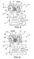
Fig. 5 is a front elevation representing how five wire harnesses are held in the clamp diagrammed inFig. 2 . -
Fig. 6 is a front elevation representing how six wire harnesses are held in the clamp diagrammed inFig. 2 . -
Fig. 7 is a front elevation representing how eight wire harnesses are held in the clamp diagrammed inFig. 2 . - A
clamp 1 for a plurality of wire harnesses of small diameter, relating to one embodiment of the present invention, is now described with reference to the drawings. InFigs. 1, 2 , and3 , respectively, a plan, front elevation, and right side elevation of theclamp 1 are shown. Theclamp 1 is integrally molded of a hard plastic material.Fig. 4 diagrams the manner in which three wire harnesses 3 of small diameter are attached to apanel 2 that is the member being attached to by theclamp 1.Figs. 5, 6 and7 , respectively, diagram how 5, 6 and 8wire harnesses 3, respectively, are held in theclamp 1. - The configuration of the
clamp 1 is now described with reference toFigs. 1 to 3 . Theclamp 1 comprises apanel securing part 5 and awire harness holder 6. Thepanel securing part 5, as diagrammed inFig. 4 , has a pair ofelastic latching parts 9 for biting onto a plate-shaped attachment part 7 erected on thepanel 2. Theclamp 1, when it is pushed onto thepanel 2 so that the plate-shaped attachment part 7 diagrammed inFig. 4 is accepted between the pair ofelastic latching parts 9, is secured to thepanel 2. Theelastic latching parts 9 of thepanel securing part 5, furthermore, in the example diagrammed, are formed in shapes wherewith theattachment part 7 of thepanel 2 is accepted from the right side inFig. 2 , but theattachment part 7 of thepanel 2 may instead be of a shape that is accepted from the left side or from below. Thepanel securing part 5 may also be of some other shape, such, for example, for cases where a rod-shaped stud wherein threads or a circumferential channel is formed is erected on thepanel 2, as a shape wherewith that rod-shaped stud is accepted and latched, or, for cases where an attachment hole is formed in thepanel 2, a clip shape for insertion into and latching to that attachment hole. - The
wire harness holder 6 is securely connected to thepanel securing part 5, and, as diagrammed inFig. 1 , is of a certain width (the length in the vertical direction inFig. 1 ) so as to hold wire harnesses across a certain length. Thewire harness holder 6, as diagrammed inFig. 2 , comprises amain holder body 10 that is formed, from the open upper surface downward, in a substantially U-shaped channel shape, and acover 11 for closing the open portion of themain holder body 10. The inside of themain holder body 10 is formed downward from the top as arigid wall surface 12 that has a U-shaped channel shape, as diagrammed inFig. 2 , for accommodating and holding the plurality ofwire harnesses 3 of small diameter. At a position of an intermediate height on the U-shaped channel-shapedwall surface 12, a pair ofharness support pieces 13 is formed, extending from the side walls toward the interior of the U-shaped channel. Theharness support pieces 13 are flexed downward by the plurality of wire harnesses 3 accommodated in themain holder body 10, whereupon they elastically support the lower portions of the wire harnesses 3 in a flexed and deformed condition. Theharness support pieces 13 may be formed so that, as diagrammed inFig. 1 , one thereof (on the left side) extends across the entire width of themain holder body 10 and the other (on the right side) is shorter than the entire width of themain holder body 10, or alternatively, both of theharness support pieces 13 may be formed so as to extend across the entire width of themain holder body 10. In themain holder body 10, as diagrammed inFig. 2 , rigidharness accepting parts 14 are provided in a pair, at positions adjacent to the open portion of the U-shaped channel, higher than theharness support pieces 13, for supporting wire harnesses accepted into the U-shaped channel space and restricting them so that they do not spread out to both sides. Theseharness accepting parts 14 also work together with theharness support pieces 13, functioning so as to envelope the plurality of wire harnesses 3 of small diameter from the upper parts thereof on both sides. Theharness accepting parts 14, as diagrammed inFig. 1 , are formed to a length that is substantially half the width of themain holder body 10. That length may instead be the entire width of themain holder body 10. Theharness accepting parts 14 are rigid, while theharness support pieces 13 are elastic; wherefore, if the number of wire harnesses 3 increases, the plurality of wire harnesses 3 will flex theharness support pieces 13 downward, and some of the wire harnesses will be pushed downward to the bottom wall of themain holder body 10, as diagrammed inFigs. 5 to 7 . - A latching
part 15, wherein is formed a latching shoulder for latching with lockingpawls cover 11, is formed on the side of themain holder body 10 opposite thecover 11. The latchingpart 15 is formed on the back surface side of theharness accepting part 14 that is on the left inFig. 2 , as indicated by a broken line. - Furthermore, a
rib 17 is formed at the boundary between the bottom of themain holder body 10 and the upper side wall of thepanel securing part 5, for increasing the connection strength. - One end of the
cover 11 is connected to one side of themain holder body 10 by ahinge 18 that is in the form of a thin plate, so that that cover is capable of turning about thehinge 18. Thecover 11 turns about thehinge 18, closes themain holder body 10 at the top of the plurality of wire harnesses 3 accommodated and held between the pair ofharness support pieces 13 and the pair ofharness accepting parts 14 and prevents the wire harnesses 3 from pulling out. For that reason, a lockingpart 19 is formed at the tip end (the upper end inFig. 2 ) of thecover 11. In the lockingpart 19, afirst locking pawl 21 and asecond locking pawl 22 are formed for latching on the latchingpart 15 of themain holder body 10. Thefirst locking pawl 21 is formed at the tip end of the lockingpart 19 that is formed in an inverted L shape as diagrammed inFig. 2 , while thesecond locking pawl 22 is formed more toward the root thereof than is thefirst locking pawl 21. Thefirst locking pawl 21, when it latches on the latchingpart 15, closes thecover 11 in an attitude such that that cover is angled upward on the left side, as diagrammed inFig. 5 andFig. 7 , slightly widening the upper part of the space in themain holder body 10 where the wire harnesses are supported so as to increase the number of wire harnesses that can be accommodated therein. Thesecond locking pawl 22, when it latches on the latchingpart 15, closes thecover 11 in a horizontal attitude, as diagrammed inFig. 4 andFig. 6 , accommodating the wire harnesses only in the space inside themain holder body 10, without widening the upper part of the space wherein the wire harnesses are supported in themain holder body 10. The latching of thefirst locking pawl 21 or of thesecond locking pawl 22 is selected according to the number of wire harnesses 3 to be held, as diagrammed inFigs. 4 to 7 . This is because, depending on the number of wire harnesses 3 to be held, not only will the accommodating capacity increase or decrease, but, as diagrammed inFigs. 4 to 7 , the degree of deformation in the elasticharness support pieces 13 will differ, depending on the number of wire harnesses 3 to be held, and the accommodating capacity between theharness support pieces 13 and theharness accepting parts 14 will change. The latching positions of thefirst locking pawl 21 and second lockingpawl 22, respectively, are selected according to the diameters and number of wire harnesses 3 to be held and the geometric dimensions of the accommodating shape. - In the
cover 11, furthermore, harnesspressing pieces 23 are formed which function both to elastically support and envelope the upper parts of the plurality of wire harnesses 3 accommodated between the elasticharness support pieces 13 and the rigidharness accepting parts 14. In theharness pressing pieces 23, tip parts 25 (Fig. 2 ) are formed so as to elastically press the wire harnesses between the pair ofharness accepting parts 14. Theharness pressing pieces 23 and thetip parts 25, in the examples diagrammed inFig. 3 , are formed on both sides of thecover 11 in the width dimension (the left and right directions inFig. 3 ), with the lockingpart 19 between them; however, in another example, they may be formed so as to extend across the entire width of themain holder body 10. Theharness pressing pieces 23, working together with theharness support pieces 13 andharness accepting parts 14, function so as to envelop the entirety of the plurality of wire harnesses 3. As diagrammed inFigs. 4 to 7 , the wire harnesses 3 are supported at the bottom by the pair ofharness support pieces 13, are restricted at both sides by the pair ofharness accepting parts 14 and are elastically pressed down from the top by theharness pressing pieces 23 having theelastic tip parts 25. As a result, the wire harnesses 3 are enveloped such that the entire outer circumference thereof is elastically pressed against by theharness support pieces 13, theharness accepting parts 14 and theharness pressing pieces 23, with the same effectiveness as though wrapped with tape. Not only can the noisy shifting about thereof in directions perpendicular to the axial dimension of the wire harnesses be prevented thereby, but the wire harnesses can also be prevented from sliding in the axial direction thereof. - As diagrammed in
Fig. 2 , moreover, the portion of thecover 11 adjacent to thethin hinge 18 is formed as arigid wall 26 extending to the left. Thereby, when turned about thehinge 18 and closed, thecover 11 becomes horizontal at a certain height relative to themain holder body 10, and theharness pressing pieces 23 of thecover 11 close the upper part of themain holder body 10 in a suitable attitude. - In the
rigid wall 26, as indicated by a broken line inFig. 2 , a window-shapedlatching hole 27 is formed, open below and on the right side. In themain holder body 10 at a position adjacent to theharness accepting part 14 on the side nearest thecover 11, aprojection 29 is provided, oriented toward the latchinghole 27. When thecover 11 is turned about thehinge 18, theprojection 29 is inserted into the latchinghole 27 formed in therigid wall 26. More specifically, when thecover 11 turns about thehinge 18 and a locking pawl of the lockingpart 19 latches with the lockingpart 19, theprojection 29 is inserted into the latchinghole 27 and latches on a latching shoulder formed in the latchinghole 27, whereupon thecover 11 locks in a closed condition. As a consequence, even should thethin hinge 18 break for some reason, thecover 11 will be maintained in the closed and locked condition, and the wire harnesses 3 will be maintained in a held condition. - The manner in which three
wire harnesses 3 of small diameter are attached to a member being attached to such as apanel 2, using theclamp 1 configured as described, is diagrammed inFig. 4 . The threewire harnesses 3 of small diameter are accommodated in the accommodating space between theharness support pieces 13 andharness accepting parts 14 of themain holder body 10, thecover 11 is turned about thehinge 18, and thefirst locking pawl 21 of the lockingpart 19 latches on the latching shoulder of the latchingpart 15 of themain holder body 10; however, in the case of threewire harnesses 3, thecover 11 can be pushed in further, whereupon thesecond locking pawl 22 latches on the latching shoulder of the latchingpart 15. Thereby, thecover 11 is locked in a closed condition. In this locked condition, theprojection 29 in themain holder body 10 is inserted into the latchinghole 27 in therigid wall 26 of thecover 11, thereby contributing to thehinge 18 in securely maintaining a locked condition. When the wire harnesses 3 are long, a plurality of theseclamps 1 are attached at a plurality of locations on the wire harnesses 3. When wire harnesses are being attached to an automobile panel, moreover, theclamps 1 are attached at prescribed locations on the wire harnesses according to the layout in which the wire harnesses are deployed. After that is done, theelastic latching parts 9 of thepanel securing parts 5 are oriented toward theattachment parts 7 erected on thepanel 2 and pushed on, whereupon thepanel securing parts 5 are secured to thepanel 2, and the threewire harnesses 3 are attached to thepanel 2 by theclips 1. - The three
wire harnesses 3 of small diameter are accommodated in thewire harness holder 6, in the space between the pair ofharness support pieces 13 and the pair ofharness accepting parts 14, inside themain holder body 10. Themain holder body 10 has turned about thehinge 18, the lockingpart 19 is in a position where it latches with the latchingpart 15 of themain holder body 10, and thesecond locking pawl 22 has latched on the latching shoulder of the latchingpart 15. Thereby, thetip parts 25 of theharness pressing pieces 23 are elastically flexed and pressed against the upper parts of the threewire harnesses 3 so as to envelope them. The threewire harnesses 3 are enveloped such that the entire outer circumference thereof is elastically pressed against by theharness support pieces 13, theharness accepting parts 14, and theharness pressing pieces 23, with the same effectiveness as though wrapped with tape. Not only can the noisy shifting about thereof in directions perpendicular to the axial dimension of the wire harnesses 3 be prevented thereby, but the wire harnesses can also be prevented from sliding in the axial direction thereof. -
Figs. 5 to 7 diagram how different numbers of wire harnesses 3 are held by theclamp 1. InFig. 5 , five wire harnesses 3 are held in theclamp 1. In this case, thefirst locking pawl 21 of the lockingpart 19 is latched on the latching shoulder of the latchingpart 15. Even in this locked condition, the five wire harnesses 3 are enveloped such that the entire outer circumference thereof is elastically pressed against by theharness support pieces 13, theharness accepting parts 14 and theharness pressing pieces 23, with the same effectiveness as though wrapped with tape. Not only can the noisy shifting about thereof in directions perpendicular to the axial dimension of the wire harnesses 3 be prevented thereby, but the wire harnesses can also be prevented from sliding in the axial direction thereof. InFig. 6 , six wire harnesses 3 are held by theclamp 1. In this case, thesecond locking pawl 22 of the lockingpart 19 is latched on the latching shoulder of the latchingpart 15. In this locked condition, thewire harness 3 at the bottom makes contact with the bottom wall of themain holder body 10; but in this condition also, the six wire harnesses 3 are enveloped such that the entire outer circumference thereof is elastically pressed against by theharness support pieces 13, theharness accepting parts 14 and theharness pressing pieces 23, with the same effectiveness as though wrapped with tape. Not only can the noisy shifting about thereof in directions perpendicular to the axial dimension of the wire harnesses 3 be prevented thereby, but the wire harnesses can also be prevented from sliding in the axial direction thereof. In the case diagrammed inFig. 7 , eight wire harnesses 3 are held by theclamp 1. Thefirst locking pawl 21 of the lockingpart 19 is latched on the latching shoulder of the latchingpart 15. In this locked condition also, thelowermost wire harness 3 makes contact with the bottom wall of themain holder body 10, but the eight wire harnesses 3 are enveloped such that the entire outer circumference thereof is elastically pressed against by theharness support pieces 13, theharness accepting parts 14 and theharness pressing pieces 23, with the same effectiveness as though wrapped with tape. Not only can the noisy shifting about thereof in directions perpendicular to the axial dimension of the wire harnesses 3 be prevented thereby, but the wire harnesses can also be prevented from sliding in the axial direction thereof. - The strength wherewith the
tip parts 25 of theharness pressing pieces 23 flex, that is, the strength wherewith they press against the wire harnesses, can be selected so that in any of the cases diagrammed inFigs. 4 to 7 , the wire harnesses 3 will be enveloped such that the entire outer circumference thereof will be elastically pressed against by theharness support pieces 13, theharness accepting parts 14 and theharness pressing pieces 23, with the same effectiveness as though wrapped with tape. - As described above, from 3 to 8 wire harnesses 3 of small diameter can be held with the
same clamp 1 in the same manner as though wrapped with tape, and the operation of attaching them to a panel or the like can easily be performed. Accordingly, with theclamp 1, not only can tedious tape-wrapping operations be done away with, but different numbers of wire harnesses can be held by the same clamp, so that clamps can be commonly used. In addition, because the operation of attaching wire harnesses to a member being attached to with a clamp is made easy, wire harness attachment operations can be accomplished in a shorter time, without requiring any special skill.
Claims (7)
- A clamp (1) having a wire harness holder (6) for holding a plurality of wire harnesses (3) wherein:said wire harness holder (6) comprises: a main holder body (10) formed in a U-shaped channel shape, the upper part whereof is open, wherein is formed a space for accommodating a plurality of wire harnesses (3); and a cover (11) for closing the open upper part of said main holder body (10); wherein:an elastic flexible harness support piece (13) for elastically supporting a plurality of wire harnesses (3) from below is formed in said main holder body (10) at a position of inter-mediate height in said U-shaped channel-shaped space; and a rigid harness accepting part (14) for supporting and restricting the plurality of wire harnesses (3) so that they do not spread out to both sides is also formed in said main holder body (10) at a position that is above said harness support piece (13) and adjacent to the opening of said U-shaped channel-shaped space; andan elastic harness pressing piece (23), for closing the opening in said U-shaped channel-shaped space, when said cover (11) is closed, and elastically pressing on the upper part of the plurality of wire harnesses (3), is formed in said cover (11); wherewith:the overall outer circumference of the plurality of wire harnesses (3) accommodated in said U-shaped channel-shaped space is enveloped so as to be elastically pressed against by said harness support piece (13), said harness accepting part (14), and said harness pressing piece (23); the wire harnesses (3) are prevented from sliding in the axial direction; and any noisy shifting about thereof in directions perpendicular to said axial direction is prevented.
- The clamp according to claim 1, wherein one end of said cover (11) is connected by a hinge (18) to one side of said main holder body (10), and the cover (11) turns about said hinge (18) to close the open portion of said main holder body (10).
- The clamp according to claim 2, wherein a locking part (19) is formed in said cover (11) on the opposite end from said hinge; and a latching part (15) for latching with said locking part (19) is formed in said main holder body (10) on the opposite side from said hinge (18); whereupon, when the cover (11) turns about said hinge (18) and closes the opening in said main holder body (10), said locking part (19) latches with said latching part (19) and the closed condition of said open portion is maintained.
- The clamp according to claim 3, wherein said locking part (19) has a first locking pawl (21) and a second locking pawl (22) for latching with said latching part (15); said first locking pawl (21) is formed at a position where it will latch with said latching part (15) when said cover (11) is in an attitude such that the space in the upper part of the wire harness accommodating space of said main holder body (10) is slightly widened; and the second locking pawl (22) is formed at a position where it will latch with said latching part (15) when said cover (11) is in an attitude such that the space in the upper part of the wire harness accommodating space of said main holder body (10) is not widened.
- The clamp according to any one of claims 1 to 4, wherein said harness support piece (13) and said harness accepting part (14), respectively, are formed in pairs thereof, so as to protrude to the inside of said U-shaped channel-shaped space.
- The clamp according to any one of claims 1 to 5, wherein, furthermore, a panel securing part (5) that is to be secured to a panel (2) or other member being attached to is integrally formed in said wire harness holder (6).
- The clamp according to claim 6, wherein said panel securing part (5) has a pair of elastic latching parts (9) for clamping a plate-shaped attachment part (7) erected on a panel (2).
Applications Claiming Priority (1)
| Application Number | Priority Date | Filing Date | Title |
|---|---|---|---|
| JP2007280475A JP2009112092A (en) | 2007-10-29 | 2007-10-29 | Clamp for multiple wiring harnesses |
Publications (2)
| Publication Number | Publication Date |
|---|---|
| EP2056419A2 true EP2056419A2 (en) | 2009-05-06 |
| EP2056419A3 EP2056419A3 (en) | 2011-12-07 |
Family
ID=40280717
Family Applications (1)
| Application Number | Title | Priority Date | Filing Date |
|---|---|---|---|
| EP08018293A Withdrawn EP2056419A3 (en) | 2007-10-29 | 2008-10-20 | Clamp for a plurality of wire harnesses |
Country Status (2)
| Country | Link |
|---|---|
| EP (1) | EP2056419A3 (en) |
| JP (1) | JP2009112092A (en) |
Cited By (9)
| Publication number | Priority date | Publication date | Assignee | Title |
|---|---|---|---|---|
| US20150233495A1 (en) * | 2014-02-18 | 2015-08-20 | Newfrey Llc | Vibration-proof clamp |
| EP3203129A1 (en) | 2016-02-05 | 2017-08-09 | Hellermanntyton Corporation | Adjustable p-clamp |
| CN107902489A (en) * | 2017-10-23 | 2018-04-13 | 成都市宏山科技有限公司 | Home router cable protective device |
| CN110048351A (en) * | 2019-05-27 | 2019-07-23 | 张荣华 | A kind of motor-car cable protection fixed structure |
| CN110165611A (en) * | 2019-05-22 | 2019-08-23 | 安徽江淮汽车集团股份有限公司 | a clamp |
| US10903632B2 (en) | 2016-02-05 | 2021-01-26 | Hellermanntyton Corporation | Adjustable P-clamp with multiple mounting options |
| US12326210B2 (en) | 2022-03-24 | 2025-06-10 | Hellermanntyton Corporation | Quick attach clamp |
| US12338848B2 (en) | 2022-06-30 | 2025-06-24 | Hellermanntyton Corporation | Anti-wobble fir tree mount |
| US12460749B2 (en) | 2023-04-28 | 2025-11-04 | Hellermanntyton Corporation | Cradle mount fixings |
Families Citing this family (8)
| Publication number | Priority date | Publication date | Assignee | Title |
|---|---|---|---|---|
| JP5566654B2 (en) * | 2009-10-02 | 2014-08-06 | 川崎重工業株式会社 | Motorcycle wiring system |
| JP5857605B2 (en) * | 2011-10-07 | 2016-02-10 | 日本スタッドウェルディング株式会社 | Tube clamp |
| KR200482277Y1 (en) * | 2015-07-22 | 2017-01-06 | 박중화 | Wire connector for grape culture |
| JP6337298B2 (en) * | 2017-09-12 | 2018-06-06 | 株式会社北電子 | Game machine |
| JP7266001B2 (en) * | 2020-01-30 | 2023-04-27 | 株式会社豊田自動織機 | Wiring harness clamp structure |
| CN113113879B (en) * | 2021-04-25 | 2022-07-26 | 安徽江淮汽车集团股份有限公司 | Pipeline clamp and wire harness laying device |
| JP7668984B2 (en) * | 2021-10-21 | 2025-04-28 | トヨタ車体株式会社 | Assembly Structure |
| FR3136420B1 (en) * | 2022-06-10 | 2025-07-18 | Renault Sas | Variable shift device for a wiring harness |
Family Cites Families (6)
| Publication number | Priority date | Publication date | Assignee | Title |
|---|---|---|---|---|
| JPH0540668Y2 (en) * | 1987-08-10 | 1993-10-15 | ||
| JP2544686Y2 (en) * | 1991-11-25 | 1997-08-20 | 株式会社ニフコ | Fastener for linear objects |
| JP2001099357A (en) * | 1999-09-28 | 2001-04-10 | Piolax Inc | Pipe clip |
| JP3449971B2 (en) * | 2000-07-31 | 2003-09-22 | 北川工業株式会社 | Fixture |
| JP2005113953A (en) * | 2003-10-03 | 2005-04-28 | Nippon Pop Rivets & Fasteners Ltd | Cable clamp |
| JP4494939B2 (en) * | 2004-11-15 | 2010-06-30 | 株式会社パイオラックス | Holder clip |
-
2007
- 2007-10-29 JP JP2007280475A patent/JP2009112092A/en active Pending
-
2008
- 2008-10-20 EP EP08018293A patent/EP2056419A3/en not_active Withdrawn
Cited By (14)
| Publication number | Priority date | Publication date | Assignee | Title |
|---|---|---|---|---|
| US9273804B2 (en) * | 2014-02-18 | 2016-03-01 | Newfrey Llc | Vibration-proof clamp |
| US20150233495A1 (en) * | 2014-02-18 | 2015-08-20 | Newfrey Llc | Vibration-proof clamp |
| US10903632B2 (en) | 2016-02-05 | 2021-01-26 | Hellermanntyton Corporation | Adjustable P-clamp with multiple mounting options |
| EP3203129A1 (en) | 2016-02-05 | 2017-08-09 | Hellermanntyton Corporation | Adjustable p-clamp |
| EP3462068A1 (en) * | 2016-02-05 | 2019-04-03 | Hellermanntyton Corporation | Adjustable p-clamp |
| US11705703B2 (en) | 2016-02-05 | 2023-07-18 | Aptiv Technologies Limited | Adjustable P-clamp with multiple mounting options |
| US11355905B2 (en) | 2016-02-05 | 2022-06-07 | Hellermanntyton Corporation | Adjustable P-clamp with multiple mounting options |
| CN107902489A (en) * | 2017-10-23 | 2018-04-13 | 成都市宏山科技有限公司 | Home router cable protective device |
| CN110165611B (en) * | 2019-05-22 | 2020-12-01 | 安徽江淮汽车集团股份有限公司 | a clip |
| CN110165611A (en) * | 2019-05-22 | 2019-08-23 | 安徽江淮汽车集团股份有限公司 | a clamp |
| CN110048351A (en) * | 2019-05-27 | 2019-07-23 | 张荣华 | A kind of motor-car cable protection fixed structure |
| US12326210B2 (en) | 2022-03-24 | 2025-06-10 | Hellermanntyton Corporation | Quick attach clamp |
| US12338848B2 (en) | 2022-06-30 | 2025-06-24 | Hellermanntyton Corporation | Anti-wobble fir tree mount |
| US12460749B2 (en) | 2023-04-28 | 2025-11-04 | Hellermanntyton Corporation | Cradle mount fixings |
Also Published As
| Publication number | Publication date |
|---|---|
| JP2009112092A (en) | 2009-05-21 |
| EP2056419A3 (en) | 2011-12-07 |
Similar Documents
| Publication | Publication Date | Title |
|---|---|---|
| JP5066731B2 (en) | Multiple wire harness clamps | |
| JP2009112092A (en) | Clamp for multiple wiring harnesses | |
| US7294789B1 (en) | Retainer with band clip and cable holder | |
| JP4257288B2 (en) | Clamp for long member | |
| US11162523B2 (en) | Push pin with antirotational stopper and method of use thereof | |
| US5601261A (en) | Band clip | |
| JP2012029449A (en) | Harness protector and wire harness routing structure | |
| JP2003348742A (en) | Attachment for long member | |
| US7533853B2 (en) | Clip structure and wire-like member fixing method | |
| JP4264297B2 (en) | Clips for fixing tubes and linear objects | |
| JP4494939B2 (en) | Holder clip | |
| JP2020072583A (en) | Connector and wire harness | |
| US6003852A (en) | Assembly device for a wiring harness | |
| US4978091A (en) | Bundling strap | |
| JP2002225647A (en) | Securing clip | |
| JP3977179B2 (en) | Band clamp | |
| US7294784B2 (en) | Electric supply apparatus | |
| JP4191083B2 (en) | Belt clamp | |
| KR200388148Y1 (en) | Wire harness fix clip | |
| JP2010266053A (en) | clip | |
| JP2008154343A (en) | Retaining tool for holding the corrugated tube | |
| JPH0240370Y2 (en) | ||
| JP4459868B2 (en) | Cable clip | |
| KR200431313Y1 (en) | Clip for fixing wire harness | |
| JP3468829B2 (en) | Belt clamp |
Legal Events
| Date | Code | Title | Description |
|---|---|---|---|
| PUAI | Public reference made under article 153(3) epc to a published international application that has entered the european phase |
Free format text: ORIGINAL CODE: 0009012 |
|
| AK | Designated contracting states |
Kind code of ref document: A2 Designated state(s): AT BE BG CH CY CZ DE DK EE ES FI FR GB GR HR HU IE IS IT LI LT LU LV MC MT NL NO PL PT RO SE SI SK TR |
|
| AX | Request for extension of the european patent |
Extension state: AL BA MK RS |
|
| PUAL | Search report despatched |
Free format text: ORIGINAL CODE: 0009013 |
|
| AK | Designated contracting states |
Kind code of ref document: A3 Designated state(s): AT BE BG CH CY CZ DE DK EE ES FI FR GB GR HR HU IE IS IT LI LT LU LV MC MT NL NO PL PT RO SE SI SK TR |
|
| AX | Request for extension of the european patent |
Extension state: AL BA MK RS |
|
| RIC1 | Information provided on ipc code assigned before grant |
Ipc: B60R 16/02 20060101ALI20111103BHEP Ipc: F16L 3/10 20060101ALI20111103BHEP Ipc: H02G 3/32 20060101AFI20111103BHEP |
|
| AKY | No designation fees paid | ||
| REG | Reference to a national code |
Ref country code: DE Ref legal event code: R108 Effective date: 20120816 |
|
| STAA | Information on the status of an ep patent application or granted ep patent |
Free format text: STATUS: THE APPLICATION IS DEEMED TO BE WITHDRAWN |
|
| 18D | Application deemed to be withdrawn |
Effective date: 20120503 |