EP2056392A1 - Battery pack and battery pack separator - Google Patents
Battery pack and battery pack separator Download PDFInfo
- Publication number
- EP2056392A1 EP2056392A1 EP20080018669 EP08018669A EP2056392A1 EP 2056392 A1 EP2056392 A1 EP 2056392A1 EP 20080018669 EP20080018669 EP 20080018669 EP 08018669 A EP08018669 A EP 08018669A EP 2056392 A1 EP2056392 A1 EP 2056392A1
- Authority
- EP
- European Patent Office
- Prior art keywords
- battery
- separator
- battery cells
- battery pack
- block
- Prior art date
- Legal status (The legal status is an assumption and is not a legal conclusion. Google has not performed a legal analysis and makes no representation as to the accuracy of the status listed.)
- Granted
Links
Images






Classifications
-
- H—ELECTRICITY
- H01—ELECTRIC ELEMENTS
- H01M—PROCESSES OR MEANS, e.g. BATTERIES, FOR THE DIRECT CONVERSION OF CHEMICAL ENERGY INTO ELECTRICAL ENERGY
- H01M6/00—Primary cells; Manufacture thereof
- H01M6/50—Methods or arrangements for servicing or maintenance, e.g. for maintaining operating temperature
- H01M6/5038—Heating or cooling of cells or batteries
-
- H—ELECTRICITY
- H01—ELECTRIC ELEMENTS
- H01M—PROCESSES OR MEANS, e.g. BATTERIES, FOR THE DIRECT CONVERSION OF CHEMICAL ENERGY INTO ELECTRICAL ENERGY
- H01M10/00—Secondary cells; Manufacture thereof
- H01M10/60—Heating or cooling; Temperature control
- H01M10/61—Types of temperature control
- H01M10/613—Cooling or keeping cold
-
- H—ELECTRICITY
- H01—ELECTRIC ELEMENTS
- H01M—PROCESSES OR MEANS, e.g. BATTERIES, FOR THE DIRECT CONVERSION OF CHEMICAL ENERGY INTO ELECTRICAL ENERGY
- H01M10/00—Secondary cells; Manufacture thereof
- H01M10/60—Heating or cooling; Temperature control
- H01M10/62—Heating or cooling; Temperature control specially adapted for specific applications
- H01M10/625—Vehicles
-
- H—ELECTRICITY
- H01—ELECTRIC ELEMENTS
- H01M—PROCESSES OR MEANS, e.g. BATTERIES, FOR THE DIRECT CONVERSION OF CHEMICAL ENERGY INTO ELECTRICAL ENERGY
- H01M10/00—Secondary cells; Manufacture thereof
- H01M10/60—Heating or cooling; Temperature control
- H01M10/64—Heating or cooling; Temperature control characterised by the shape of the cells
- H01M10/647—Prismatic or flat cells, e.g. pouch cells
-
- H—ELECTRICITY
- H01—ELECTRIC ELEMENTS
- H01M—PROCESSES OR MEANS, e.g. BATTERIES, FOR THE DIRECT CONVERSION OF CHEMICAL ENERGY INTO ELECTRICAL ENERGY
- H01M10/00—Secondary cells; Manufacture thereof
- H01M10/60—Heating or cooling; Temperature control
- H01M10/65—Means for temperature control structurally associated with the cells
- H01M10/655—Solid structures for heat exchange or heat conduction
- H01M10/6554—Rods or plates
- H01M10/6555—Rods or plates arranged between the cells
-
- H—ELECTRICITY
- H01—ELECTRIC ELEMENTS
- H01M—PROCESSES OR MEANS, e.g. BATTERIES, FOR THE DIRECT CONVERSION OF CHEMICAL ENERGY INTO ELECTRICAL ENERGY
- H01M10/00—Secondary cells; Manufacture thereof
- H01M10/60—Heating or cooling; Temperature control
- H01M10/65—Means for temperature control structurally associated with the cells
- H01M10/655—Solid structures for heat exchange or heat conduction
- H01M10/6556—Solid parts with flow channel passages or pipes for heat exchange
- H01M10/6557—Solid parts with flow channel passages or pipes for heat exchange arranged between the cells
-
- H—ELECTRICITY
- H01—ELECTRIC ELEMENTS
- H01M—PROCESSES OR MEANS, e.g. BATTERIES, FOR THE DIRECT CONVERSION OF CHEMICAL ENERGY INTO ELECTRICAL ENERGY
- H01M10/00—Secondary cells; Manufacture thereof
- H01M10/60—Heating or cooling; Temperature control
- H01M10/65—Means for temperature control structurally associated with the cells
- H01M10/656—Means for temperature control structurally associated with the cells characterised by the type of heat-exchange fluid
- H01M10/6561—Gases
- H01M10/6563—Gases with forced flow, e.g. by blowers
-
- H—ELECTRICITY
- H01—ELECTRIC ELEMENTS
- H01M—PROCESSES OR MEANS, e.g. BATTERIES, FOR THE DIRECT CONVERSION OF CHEMICAL ENERGY INTO ELECTRICAL ENERGY
- H01M10/00—Secondary cells; Manufacture thereof
- H01M10/60—Heating or cooling; Temperature control
- H01M10/65—Means for temperature control structurally associated with the cells
- H01M10/656—Means for temperature control structurally associated with the cells characterised by the type of heat-exchange fluid
- H01M10/6561—Gases
- H01M10/6566—Means within the gas flow to guide the flow around one or more cells, e.g. manifolds, baffles or other barriers
-
- H—ELECTRICITY
- H01—ELECTRIC ELEMENTS
- H01M—PROCESSES OR MEANS, e.g. BATTERIES, FOR THE DIRECT CONVERSION OF CHEMICAL ENERGY INTO ELECTRICAL ENERGY
- H01M50/00—Constructional details or processes of manufacture of the non-active parts of electrochemical cells other than fuel cells, e.g. hybrid cells
- H01M50/20—Mountings; Secondary casings or frames; Racks, modules or packs; Suspension devices; Shock absorbers; Transport or carrying devices; Holders
- H01M50/204—Racks, modules or packs for multiple batteries or multiple cells
- H01M50/207—Racks, modules or packs for multiple batteries or multiple cells characterised by their shape
- H01M50/209—Racks, modules or packs for multiple batteries or multiple cells characterised by their shape adapted for prismatic or rectangular cells
-
- H—ELECTRICITY
- H01—ELECTRIC ELEMENTS
- H01M—PROCESSES OR MEANS, e.g. BATTERIES, FOR THE DIRECT CONVERSION OF CHEMICAL ENERGY INTO ELECTRICAL ENERGY
- H01M50/00—Constructional details or processes of manufacture of the non-active parts of electrochemical cells other than fuel cells, e.g. hybrid cells
- H01M50/20—Mountings; Secondary casings or frames; Racks, modules or packs; Suspension devices; Shock absorbers; Transport or carrying devices; Holders
- H01M50/289—Mountings; Secondary casings or frames; Racks, modules or packs; Suspension devices; Shock absorbers; Transport or carrying devices; Holders characterised by spacing elements or positioning means within frames, racks or packs
- H01M50/291—Mountings; Secondary casings or frames; Racks, modules or packs; Suspension devices; Shock absorbers; Transport or carrying devices; Holders characterised by spacing elements or positioning means within frames, racks or packs characterised by their shape
-
- H—ELECTRICITY
- H01—ELECTRIC ELEMENTS
- H01M—PROCESSES OR MEANS, e.g. BATTERIES, FOR THE DIRECT CONVERSION OF CHEMICAL ENERGY INTO ELECTRICAL ENERGY
- H01M10/00—Secondary cells; Manufacture thereof
- H01M10/05—Accumulators with non-aqueous electrolyte
- H01M10/052—Li-accumulators
- H01M10/0525—Rocking-chair batteries, i.e. batteries with lithium insertion or intercalation in both electrodes; Lithium-ion batteries
-
- H—ELECTRICITY
- H01—ELECTRIC ELEMENTS
- H01M—PROCESSES OR MEANS, e.g. BATTERIES, FOR THE DIRECT CONVERSION OF CHEMICAL ENERGY INTO ELECTRICAL ENERGY
- H01M10/00—Secondary cells; Manufacture thereof
- H01M10/24—Alkaline accumulators
- H01M10/30—Nickel accumulators
-
- Y—GENERAL TAGGING OF NEW TECHNOLOGICAL DEVELOPMENTS; GENERAL TAGGING OF CROSS-SECTIONAL TECHNOLOGIES SPANNING OVER SEVERAL SECTIONS OF THE IPC; TECHNICAL SUBJECTS COVERED BY FORMER USPC CROSS-REFERENCE ART COLLECTIONS [XRACs] AND DIGESTS
- Y02—TECHNOLOGIES OR APPLICATIONS FOR MITIGATION OR ADAPTATION AGAINST CLIMATE CHANGE
- Y02E—REDUCTION OF GREENHOUSE GAS [GHG] EMISSIONS, RELATED TO ENERGY GENERATION, TRANSMISSION OR DISTRIBUTION
- Y02E60/00—Enabling technologies; Technologies with a potential or indirect contribution to GHG emissions mitigation
- Y02E60/10—Energy storage using batteries
Definitions
- the present invention relates to a battery pack and battery pack separator used in applications such as a car power source apparatus.
- a car power source apparatus In a car power source apparatus, many individual batteries (battery cells) are connected in series to increase output voltage and output power. Since this power source apparatus is charged and discharged with high currents, battery temperatures rise. Further, because the power source apparatus must be usable even in extreme high temperature environments, forced cooling of the batteries is essential. Power source apparatus on-board present day hybrid cars are cooled by forced ventilation of the batteries with cooling air delivered by fan. Since batteries in these power source apparatus are cooled by air, rapid cooling is difficult when abnormal battery temperature rise occurs. Further, because ventilation and cooling is via air, which has low heat capacity, it is difficult to cool many batteries to a uniform temperature.
- FIG. 1 As a battery pack to correct these drawbacks, Japanese Patent Application Disclosure 2004-362879 describes a cooling configuration as shown in Fig. 1 .
- cooling air channels 72 are established by separators 70 disposed between adjacent battery cells 71, and cooling air is delivered through those cooling air channels 72.
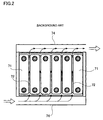
- a battery pack having this type of structure is shown in the plan view of Fig. 2 .
- cooling air is delivered into an air duct 74 provided along the battery cell 71 stacking direction of one side (bottom side in Fig. 2 ) of the battery pack. This cooling air is divided, passed through the cooling air channels 72 formed between adjacent battery cells 71, collected at the opposite side (top side in Fig. 2 ) of the battery pack, and discharged to the outside.
- the air ducts extend in the battery cell stacking direction while cooling air channels extend in a direction perpendicular to that. Therefore, the path of airflow makes a right angle and turbulent flow is easily generated near cooling air channel entranceways. Similarly, turbulent flow is easily generated at the exit-side of the cooling air channels. Consequently, pressure losses further increase.
- the present invention was developed to resolve these types of problems. Thus, it is one object of the present invention to provide a battery pack and battery pack separator that reduces generation of pressure losses to achieve more uniform battery cooling.
- the first battery pack of the present invention is provided with a plurality of battery cells, and insulating separators disposed between adjacent battery cells, where the plurality of battery cells are disposed in a stacked configuration with a prescribed gap between adjacent battery cells.
- a separator is provided with a plurality of gas channels that enable the flow of cooling gas.
- the gas channels have cooling gas entranceways and exit ways, which open at the sides of the battery block formed by the stacked battery cells.
- a separator has cut sections formed to position the entranceways and exit ways of the gas channels inward from the sides of the battery block. This allows cooling gas near entranceways and exit ways to be smoothly introduced to, and exhausted from the gas channels, and reduces cooling gas pressure losses in those regions.
- the pressure difference between the input-side and output-side is also reduced, and cooling capability can approach uniformity.
- the second battery pack of the present invention is provided with a plurality of battery cells, and insulating separators disposed between adjacent battery cells, where the plurality of battery cells are disposed in a stacked configuration with a prescribed gap between adjacent battery cells.
- a separator is provided with a plurality of gas channels that enable the flow of cooling gas.
- the gas channels have cooling gas entranceways and exit ways, which open at the sides of the battery block formed by the stacked battery cells.
- a separator has a cut section formed to position at least the entranceways of the gas channels inward from the sides of the battery block. This allows cooling gas near entranceways, believed related to particularly large pressure losses, to be smoothly introduced to, and exhausted from the gas channels, and this reduces cooling gas pressure losses in those regions.
- the pressure difference between the input-side and output-side is also reduced, and cooling capability can approach uniformity.
- a separator in the third battery pack, can be formed with its battery block side-facing edges positioned, except for battery cell corner regions, interior to the sides of the battery block by an approximately constant standoff distance. This allows cooling gas introduction to each gas channel under approximately the same conditions, and allows capability for more uniform cooling.
- a separator in the fourth battery pack, can be formed with its battery block side-facing edges displaced a distance inward from the sides of the battery block, and that distance increases from battery block corner regions towards the center. This allows cooling gas introduction to gas channels over a wide area near the center region while maintaining electrical insulation by covering battery cell corner regions with separator corners. This configuration has the merit that pressure losses near center regions are reduced and cooling capability can be enhanced.
- a separator can be formed, except at battery cell corner regions, with its battery block side-facing edges displaced a distance inward from the sides of the battery block, and that distance decreases from battery block corner regions towards the center. This can maintain electrical insulation by covering battery cell corner regions with separator corners, and can cover wide areas of battery cell surface at center regions. This configuration can sustain electrical isolation even when a battery cell external case expands due to conditions such as an increase in internal battery pressure.
- a separator in the sixth battery pack, can be formed with its battery block side-facing edges made thinner except at battery cell corner regions. This can maintain separator strength with thick corner regions while reducing pressure losses by thinning other regions near the sides of the battery block. In addition, since electrical isolation can be maintained by local separator thinning instead of establishing cut sections, short-circuiting between battery cells can be prevented and safety improved.
- a plurality of parallel gas channels can be established in straight lines from one side of the battery block to the other side.
- gas channels with rectangular cross-sections can be formed by providing a plurality of troughs and protrusions in separator surfaces. Separator troughs are closed off by battery cell surfaces to form gas channels with rectangular cross-sections.
- the external shape of the battery cells can be approximately rectangular. This takes advantage of the merit of a rectangular battery pack well suited for size reduction. Specifically, cooling capability can be improved without changing the width of gas channels between battery cells.
- the external shape of the battery cells can be circular cylindrical. This allows circular cylindrical batteries as well as rectangular batteries to be used beneficially in the present invention.
- the eleventh battery pack separator is an insulating separator inserted between adjacent battery cells, where a plurality of battery cells makes up the battery pack.
- a separator is provided with a plurality of gas channels that enable the flow of cooling gas.
- the gas channels have cooling gas entranceways and exit ways, which open at the sides of the battery block formed by the stacked battery cells.
- a separator has cut sections formed to position the entranceways and exit ways of the gas channels inward from the sides of the battery block. This allows cooling gas near entranceways and exit ways to be smoothly introduced to, and exhausted from the gas channels, and reduces cooling gas pressure losses in those regions. The pressure difference between the input-side and output-side is also reduced, and cooling capability can approach uniformity.
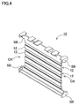
- Figs. 3 and 4 show an exploded oblique view of a battery pack 100 for the first form of embodiment of the present invention and an oblique view of a separator respectively.
- Figs. 5 and 6 show an exploded oblique view of a battery pack 500 that uses a prior art separator and an oblique view of that separator respectively.
- These battery packs are made up of battery blocks having a plurality of battery cells 1 stacked in the same orientation. Separators 10, 60 are sandwiched between adjacent battery cells 1. Endplates 20 are disposed at both ends of a battery block, and these endplates 20 are held in position, with the battery block in between, by lengthwise retaining rails 22.
- the battery block shown in Fig. 3 is a battery block for use on-board a car.
- the battery block is configured with a plurality of battery cells 1 and separators 10 stacked alternately and covered at the left and right ends by endplates 20.
- rectangular battery cells 1 are sandwiched by frame-shaped separators 10 and stacked in multiple tiers while exposing the top and side surfaces of the battery cells 1.
- 18 battery cells 1 are stacked on their primary (largest area) surfaces.
- Rectangular batteries enclosed by an external case with an approximately rectangular shape are used as battery cells 1.
- a rectangular battery cell is formed in the shape of a thin box that is thinner than it is wide, and preferably has truncated edge regions.
- rectangular battery cells can be arranged more efficiently to increase energy density in a given volume. This is particularly desirable for applications on-board cars where space reduction is an important requirement.
- circular cylindrical batteries can also be used.
- Rectangular rechargeable batteries such as lithium ion rechargeable batteries can be used as battery cells.
- other battery types such as nickel batteries, and even primary (non-rechargeable) batteries can be used.
- Output terminals 2 of each battery cell 1 are wired together in series or parallel.
- control circuit (not illustrated) is connected in the battery pack end region. Parameters such as battery cell 1 voltage, current, and temperature are measured by the control circuit, and battery capacity, required charge and discharge capacity, etc. are determined to control operations such as charging and discharging.
- a battery cell 1 has positive and negative output terminals 2 projecting from the upper surface of a rectangular external case, which has truncated edges on its sides. Output terminals 2 are positioned to project from the upper surface with left-right symmetry with respect to the primary (largest area) surfaces of the external case. As a result, when battery cells 1 are laterally flipped-over and stacked, positive electrodes and negative electrodes can line-up to allow easy connection in series. Each output terminal 2 is bent in an L-shape. Here, positive and negative output terminals 2 are bent in opposite directions as shown, for example, in Fig. 3 .
- Output terminals 2 are bent in L-shapes, connecting holes are opened through bent regions, and bolts are inserted through connecting holes to connect overlapping bent regions.
- the positive electrode and negative electrode are connected in series between adjacent batteries to connect a plurality of batteries in series.
- adjacent battery cells can also be connected in series via metal-plate bus bar connection to the output terminals 2.
- output voltage can be increased to enable large output.
- the power source apparatus can also have battery cells 1 connected in parallel and series.
- a rectangular case makes up the external case of a battery cell 1.
- Rolled electrodes are inserted into the open end of the closed-bottom rectangular cylindrical external case, liquid electrolyte is introduced, the open end is closed off with a sealing cap, and the external case is sealed closed by a technique such as laser welding.
- This rectangular case is made of metal having superior heat conduction properties.
- a safety valve is provided in the sealing cap, and if the battery is charged or discharged under abnormal conditions, the safety valve can open to discharge electrolyte.
- this battery cell 1 has vertically protruding terminal ribs established around the perimeters of output terminals 2. These terminal ribs can prevent unnecessary spreading of electrolyte liquid even if it leaks from inside the external case out around the perimeter of an output terminal 2.
- separators 10 As shown in Figs. 3 and 5 , battery cells 1 are sandwiched on both primary surfaces by separators 10 that cover those external surfaces.
- a separator 10 has a frame-shaped structure with a size that covers the four corners of a battery cell 1. When a battery cell 1 is covered by a separator 10, both side surfaces and the top and bottom surfaces are exposed while the four corner regions are covered. Further, corner regions SB of adjacently stacked separators 10 abut.
- Separators 10 are made from material with superior thermal insulating and high temperature properties, and are preferably formed from lightweight, inexpensive resin. For example, synthetic resins with low thermal conductivity (0.5W/m or less is desirable) such as polypropylene or polyurethane can be used. As a result, battery cells 1 are protected by separators 10, and adjacent battery cells 1 are both electrically and thermally insulated from one another.
- the surface of a separator 10 has a cross-section with troughs and protrusions that form slits 12.
- a cross-section of continuous troughs and protrusions By forming the separator 10 surface with a cross-section of continuous troughs and protrusions, open troughs can be closed off by contact with a battery cell 1 surface, and gas channels that laterally traverse the battery cell 1 can be easily formed.
- a plurality of parallel gas channels are established in straight lines at approximately fixed intervals in the vertical direction of a battery cell 1.
- These slits 12, which are the gas channels cool battery cells 1 by passing a cooling medium such as cooling air.
- the cooling medium is preferably air, other cooling gases can also be used as appropriate.
- the cooling medium is preferably air, other cooling gases can also be used as appropriate.
- air ducts 24 are disposed on both sides of the battery block.
- a device for ventilating cooling air such as a fan (not illustrated) is connected with the air ducts 24 to supply the air ducts 24 with cooling air.
- Air ducts 24 connect with each slit 12, which opens at the sides of the battery block and traverses across the battery block. As shown in Fig. 2 , this arrangement allows cooling air flowing through the air ducts 24 to be forced through each slit 12.
- End-planes of a battery block which has separators 10 and battery cells 1 alternately stacked and joined as described above, are covered and held in place by endplates 20.
- An endplate 20 is made with a size that allows it to cover an exposed battery cell 1 at an end of a battery block. Endplates 20 hold the battery block by sandwiching it from both ends.
- a pair of screw holes is provided at the sides of each endplate 20, and lengthwise retaining rails 22 extend along the sides of the battery pack of stacked battery cells 1 and screw-attach to both endplates 20 to hold the unit.
- Metal or resin which can preferably be molded as a single piece, can also be used to make endplates 20.
- the prior art separator 60 shown in Figs. 5 and 6 has a size and shape that can essentially cover an entire primary (largest area) surface of a battery cell 1.
- the separator 10 for the first form of embodiment shown in Figs. 3 and 4 is shaped with concavity on both sides, and as a result, is smaller than the primary surface of a battery cell 1.
- recessed cut sections CR are formed on both sides of the separators 10, and that partially exposes battery cells 1 near the sides of the battery block.
- While cut sections CR are formed inward on the primary surface of a battery cell 1, corner regions SB, which are part of the separator 10 frame, are retained, In this manner, separator strength can be maintained, while gas channel entranceways and exit ways are opened wider. This can suppress generation of turbulent flow and reduce pressure losses. Losses are particularly high when forced cooling air delivered by the air ducts is guided into narrow slits. In addition, losses are high when cooling air is redirected from its flow along the stacking direction of the battery cells 1 to a direction perpendicular to that flow.
- cut sections CR By establishing cut sections CR at the entranceway-sides of separators 10, open space is allocated at gas channel entranceways. Once cooling air flows into that open space, it is guided into gas channel slits 12.
- symmetric cut sections CR at the entranceway-side and exit way-side of a separator are preferable. In that case, either the right or left side of a separator can be used as the entranceway-side (or exit way-side).
- This type of separator 10 can be made as a single-piece by techniques such as resin molding, or a pre-formed rectangular separator can be mechanically modified to remove sections of the separator.
- the separator 10 By giving the separator 10 a shape with fixed-width cut-outs only at side edges, a wide region of the primary surface of the battery cell 1 can be covered, and insulation between battery cells 1 is maintained.
- the part of the battery cell 1 exposed by the cut section CR is the edge region of the external case, which is a structurally strong region. Therefore, even if battery cells 1 expand to some degree, contact between adjacent battery cells 1 can be avoided because there is little battery case deformation in the exposed regions.
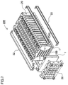
- a battery pack 200 for the second form of embodiment is shown in the exploded oblique view of Fig. 7
- its separator 10B is shown in the oblique view of Fig. 8
- the cut section CR2 of the separator 10B is further enlarged with a more concave center to give the separator 10B an hourglass shape.
- the separator 10B is configured with corner regions SB2, center regions TR positioned laterally inward from the corner regions SB2, and sloped regions KR joining the corner regions SB2 and the center regions TR.
- center regions TR have straight edges and the length of the separator 10B at its center is approximately one-third its height.
- sloped regions KR also have straight edges.
- the cut sections CR2 straight edge segments By giving the cut sections CR2 straight edge segments, separator 10B formation and post-processing can be simplified.
- the cut section can also be formed in other shapes such as a smooth semi-circular curve without limiting its structure. By making the center of the separator concave and enlarging the cut section in this fashion, pressure losses at both entranceway-sides and exit way-sides can be reduced another level.
- the separator of the second form of embodiment with its laterally narrow center region can maintain insulation between adjacent battery cells and prevent contact between those battery cells.
- sufficient insulation may not be afforded by a laterally narrow center region. Consequently, there is concern that battery cells positioned on each side of a narrow separator could contact and short-circuit.
- the battery cell surface carries an electric potential, a configuration is sought that can reliably insulate each battery cell and improve safety.
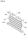
- the third form of embodiment shown in Figs. 9 and 10 has a separator 10C with a wide lateral center region, which is the inverse of that of the second form of embodiment.
- Fig. 9 shows an exploded oblique view of the battery pack 300 for the third form of embodiment
- Fig. 10 shows an oblique view of a separator 10C. Since the separator 10C shown in these figures is formed with protruding center regions TR2, a large area of the battery cell primary surface can be covered by the separator 10C. With this shape, even severe battery cell expansion can be deterred by the separator 10C and reliable insulation can be maintained between battery cells.
- separator edge gets further from the side of the battery block as the corner regions SB3 are approached, open areas are established at gas channel entranceways and exit ways near the corners and pressure losses can be reduced. Since the corner regions SB3 of the separator 10C are retained, strength of the frame-shaped separator 10C is maintained, and battery cell expansion can be countered. Since the external case of a battery cell is strong in corner regions, cell expansion in corner regions is small and short-circuiting between exposed regions of battery cells near corner regions SB3 can be precluded. In this manner, the size and shape of separator cut sections can be appropriately selected depending on the amount of expansion of the battery cells used.
- cut sections that eliminate parts of the separator are established in the previous examples, it is also possible to locally thin parts of the separator instead of eliminating the entire cut sections. Thinner separator material at entranceways and exit ways can widen open areas at those locations. Meanwhile, insulation between battery cells can be maintained to improve safety.
- cut sections are formed on both the entranceway-side and exit way-side of a separator in the previous examples, a cut section can also be formed on the entranceway-side only. This can reduce pressure loss generation at the entranceway-side, which is the side particularly susceptible to large pressure losses, to effectively improve cooling capability.
- the battery pack and battery pack separator of the present invention are suitable for use as the batteries of a car power source apparatus for a vehicle such as hybrid electric vehicles (HEV).
- HEV hybrid electric vehicles
Landscapes
- Chemical & Material Sciences (AREA)
- Chemical Kinetics & Catalysis (AREA)
- Electrochemistry (AREA)
- General Chemical & Material Sciences (AREA)
- Engineering & Computer Science (AREA)
- Manufacturing & Machinery (AREA)
- Battery Mounting, Suspending (AREA)
- Secondary Cells (AREA)
Abstract
Description
- The present invention relates to a battery pack and battery pack separator used in applications such as a car power source apparatus.
- In a car power source apparatus, many individual batteries (battery cells) are connected in series to increase output voltage and output power. Since this power source apparatus is charged and discharged with high currents, battery temperatures rise. Further, because the power source apparatus must be usable even in extreme high temperature environments, forced cooling of the batteries is essential. Power source apparatus on-board present day hybrid cars are cooled by forced ventilation of the batteries with cooling air delivered by fan. Since batteries in these power source apparatus are cooled by air, rapid cooling is difficult when abnormal battery temperature rise occurs. Further, because ventilation and cooling is via air, which has low heat capacity, it is difficult to cool many batteries to a uniform temperature.
- As a battery pack to correct these drawbacks, Japanese Patent Application Disclosure
2004-362879 Fig. 1 . Here,cooling air channels 72 are established byseparators 70 disposed betweenadjacent battery cells 71, and cooling air is delivered through thosecooling air channels 72. A battery pack having this type of structure is shown in the plan view ofFig. 2 . Here, cooling air is delivered into anair duct 74 provided along thebattery cell 71 stacking direction of one side (bottom side inFig. 2 ) of the battery pack. This cooling air is divided, passed through thecooling air channels 72 formed betweenadjacent battery cells 71, collected at the opposite side (top side inFig. 2 ) of the battery pack, and discharged to the outside. - However, uniform cooling of all
battery cells 71 without developing temperature unevenness is difficult with this structure. This is because pressure losses result when cooling air is introduced to the input-side and exhausted from the output-side of thecooling air channels 72, and differences in cooling capability develop due to pressure differences between the input-side and the output-side. Since cooling capability at the output-side is less than cooling capability at the input-side, local differences in cooling capability develop between the two sides and uniform cooling cannot be achieved. In particular, in the case of forced cooling where cooling air is introduced to the input-side by a ventilating device such as a fan, cooling air has a tendency to accumulate if the input is narrow. - Further, because of present day demand for a smaller size battery pack, large gaps cannot be allocated between battery cells. Meanwhile in contrast to the extremely narrow slit shaped cooling air channels, the widths of air duct openings are made large to supply cooling air for the many cooling air channels. Consequently, the difference in cross-sectional area between the air ducts and the cooling air channels is large, and pressure losses increase as a result. In addition, as shown in
Fig. 2 , the air ducts extend in the battery cell stacking direction while cooling air channels extend in a direction perpendicular to that. Therefore, the path of airflow makes a right angle and turbulent flow is easily generated near cooling air channel entranceways. Similarly, turbulent flow is easily generated at the exit-side of the cooling air channels. Consequently, pressure losses further increase. - The present invention was developed to resolve these types of problems. Thus, it is one object of the present invention to provide a battery pack and battery pack separator that reduces generation of pressure losses to achieve more uniform battery cooling.
- To address the problems described above, the first battery pack of the present invention is provided with a plurality of battery cells, and insulating separators disposed between adjacent battery cells, where the plurality of battery cells are disposed in a stacked configuration with a prescribed gap between adjacent battery cells. A separator is provided with a plurality of gas channels that enable the flow of cooling gas. The gas channels have cooling gas entranceways and exit ways, which open at the sides of the battery block formed by the stacked battery cells. Furthermore, a separator has cut sections formed to position the entranceways and exit ways of the gas channels inward from the sides of the battery block. This allows cooling gas near entranceways and exit ways to be smoothly introduced to, and exhausted from the gas channels, and reduces cooling gas pressure losses in those regions. The pressure difference between the input-side and output-side is also reduced, and cooling capability can approach uniformity.
- The second battery pack of the present invention is provided with a plurality of battery cells, and insulating separators disposed between adjacent battery cells, where the plurality of battery cells are disposed in a stacked configuration with a prescribed gap between adjacent battery cells. A separator is provided with a plurality of gas channels that enable the flow of cooling gas. The gas channels have cooling gas entranceways and exit ways, which open at the sides of the battery block formed by the stacked battery cells. Furthermore, a separator has a cut section formed to position at least the entranceways of the gas channels inward from the sides of the battery block. This allows cooling gas near entranceways, believed related to particularly large pressure losses, to be smoothly introduced to, and exhausted from the gas channels, and this reduces cooling gas pressure losses in those regions. The pressure difference between the input-side and output-side is also reduced, and cooling capability can approach uniformity.
- In the third battery pack, a separator can be formed with its battery block side-facing edges positioned, except for battery cell corner regions, interior to the sides of the battery block by an approximately constant standoff distance. This allows cooling gas introduction to each gas channel under approximately the same conditions, and allows capability for more uniform cooling.
- In the fourth battery pack, a separator can be formed with its battery block side-facing edges displaced a distance inward from the sides of the battery block, and that distance increases from battery block corner regions towards the center. This allows cooling gas introduction to gas channels over a wide area near the center region while maintaining electrical insulation by covering battery cell corner regions with separator corners. This configuration has the merit that pressure losses near center regions are reduced and cooling capability can be enhanced.
- In the fifth battery pack, a separator can be formed, except at battery cell corner regions, with its battery block side-facing edges displaced a distance inward from the sides of the battery block, and that distance decreases from battery block corner regions towards the center. This can maintain electrical insulation by covering battery cell corner regions with separator corners, and can cover wide areas of battery cell surface at center regions. This configuration can sustain electrical isolation even when a battery cell external case expands due to conditions such as an increase in internal battery pressure.
- In the sixth battery pack, a separator can be formed with its battery block side-facing edges made thinner except at battery cell corner regions. This can maintain separator strength with thick corner regions while reducing pressure losses by thinning other regions near the sides of the battery block. In addition, since electrical isolation can be maintained by local separator thinning instead of establishing cut sections, short-circuiting between battery cells can be prevented and safety improved.
- In the seventh battery pack, a plurality of parallel gas channels can be established in straight lines from one side of the battery block to the other side.
- In the eighth battery pack, gas channels with rectangular cross-sections can be formed by providing a plurality of troughs and protrusions in separator surfaces. Separator troughs are closed off by battery cell surfaces to form gas channels with rectangular cross-sections.
- In the ninth battery pack, the external shape of the battery cells can be approximately rectangular. This takes advantage of the merit of a rectangular battery pack well suited for size reduction. Specifically, cooling capability can be improved without changing the width of gas channels between battery cells.
- In the tenth battery pack, the external shape of the battery cells can be circular cylindrical. This allows circular cylindrical batteries as well as rectangular batteries to be used beneficially in the present invention.
- Finally, the eleventh battery pack separator is an insulating separator inserted between adjacent battery cells, where a plurality of battery cells makes up the battery pack. A separator is provided with a plurality of gas channels that enable the flow of cooling gas. The gas channels have cooling gas entranceways and exit ways, which open at the sides of the battery block formed by the stacked battery cells. Furthermore, a separator has cut sections formed to position the entranceways and exit ways of the gas channels inward from the sides of the battery block. This allows cooling gas near entranceways and exit ways to be smoothly introduced to, and exhausted from the gas channels, and reduces cooling gas pressure losses in those regions. The pressure difference between the input-side and output-side is also reduced, and cooling capability can approach uniformity. The above and further objects of the present invention as well as the features thereof will become more apparent from the following detailed description to be made in conjunction with the accompanying drawings.
-
-
Fig. 1 is an external oblique view showing a battery pack cooled by the region between battery cells; -
Fig. 2 is a plan view showing the path of cooling air delivered to gaps in the battery pack; -
Fig. 3 is an exploded oblique view showing a battery pack for the first form of embodiment of the present invention; -
Fig. 4 is an oblique view showing the separator ofFig. 3 ; -
Fig. 5 is an exploded oblique view showing a battery pack that uses a prior art separator; -
Fig. 6 is an oblique view showing the separator ofFig. 5 ; -
Fig. 7 is an exploded oblique view showing a battery pack for the second form of embodiment of the present invention; -
Fig. 8 is an oblique view showing the separator ofFig. 7 ; -
Fig. 9 is an exploded oblique view showing a battery pack for the third form of embodiment of the present invention; and -
Fig. 10 is an oblique view showing the separator ofFig. 9 . -
Figs. 3 and4 show an exploded oblique view of abattery pack 100 for the first form of embodiment of the present invention and an oblique view of a separator respectively. For comparison,Figs. 5 and6 show an exploded oblique view of abattery pack 500 that uses a prior art separator and an oblique view of that separator respectively. These battery packs are made up of battery blocks having a plurality of battery cells 1 stacked in the same orientation.Separators Endplates 20 are disposed at both ends of a battery block, and theseendplates 20 are held in position, with the battery block in between, by lengthwise retaining rails 22. - The battery block shown in
Fig. 3 is a battery block for use on-board a car. The battery block is configured with a plurality of battery cells 1 andseparators 10 stacked alternately and covered at the left and right ends byendplates 20. Specifically, rectangular battery cells 1 are sandwiched by frame-shapedseparators 10 and stacked in multiple tiers while exposing the top and side surfaces of the battery cells 1. In this example, 18 battery cells 1 are stacked on their primary (largest area) surfaces. - Rectangular batteries enclosed by an external case with an approximately rectangular shape are used as battery cells 1. A rectangular battery cell is formed in the shape of a thin box that is thinner than it is wide, and preferably has truncated edge regions. Compared with circular cylindrical batteries, rectangular battery cells can be arranged more efficiently to increase energy density in a given volume. This is particularly desirable for applications on-board cars where space reduction is an important requirement. However, depending on the application and space available, it should be understood that circular cylindrical batteries can also be used. Rectangular rechargeable batteries such as lithium ion rechargeable batteries can be used as battery cells. In addition, other battery types such as nickel batteries, and even primary (non-rechargeable) batteries can be used.
Output terminals 2 of each battery cell 1 are wired together in series or parallel. Further, a control circuit (not illustrated) is connected in the battery pack end region. Parameters such as battery cell 1 voltage, current, and temperature are measured by the control circuit, and battery capacity, required charge and discharge capacity, etc. are determined to control operations such as charging and discharging. - A battery cell 1 has positive and
negative output terminals 2 projecting from the upper surface of a rectangular external case, which has truncated edges on its sides.Output terminals 2 are positioned to project from the upper surface with left-right symmetry with respect to the primary (largest area) surfaces of the external case. As a result, when battery cells 1 are laterally flipped-over and stacked, positive electrodes and negative electrodes can line-up to allow easy connection in series. Eachoutput terminal 2 is bent in an L-shape. Here, positive andnegative output terminals 2 are bent in opposite directions as shown, for example, inFig. 3 . Not only do the ends of the bent regions ofoutput terminals 2 of adjacent battery cells 1 point in opposite directions, but they are also designed to establish a given standoff distance when battery cells 1 are in the stacked configuration.Output terminals 2 are bent in L-shapes, connecting holes are opened through bent regions, and bolts are inserted through connecting holes to connect overlapping bent regions. In this manner, the positive electrode and negative electrode are connected in series between adjacent batteries to connect a plurality of batteries in series. However, adjacent battery cells can also be connected in series via metal-plate bus bar connection to theoutput terminals 2. In a power source apparatus with battery cells 1 connected in series as described above, output voltage can be increased to enable large output. However, the power source apparatus can also have battery cells 1 connected in parallel and series. - A rectangular case makes up the external case of a battery cell 1. Rolled electrodes are inserted into the open end of the closed-bottom rectangular cylindrical external case, liquid electrolyte is introduced, the open end is closed off with a sealing cap, and the external case is sealed closed by a technique such as laser welding. This rectangular case is made of metal having superior heat conduction properties. A safety valve is provided in the sealing cap, and if the battery is charged or discharged under abnormal conditions, the safety valve can open to discharge electrolyte. In addition, this battery cell 1 has vertically protruding terminal ribs established around the perimeters of
output terminals 2. These terminal ribs can prevent unnecessary spreading of electrolyte liquid even if it leaks from inside the external case out around the perimeter of anoutput terminal 2. - As shown in
Figs. 3 and5 , battery cells 1 are sandwiched on both primary surfaces byseparators 10 that cover those external surfaces. Aseparator 10 has a frame-shaped structure with a size that covers the four corners of a battery cell 1. When a battery cell 1 is covered by aseparator 10, both side surfaces and the top and bottom surfaces are exposed while the four corner regions are covered. Further, corner regions SB of adjacently stackedseparators 10 abut.Separators 10 are made from material with superior thermal insulating and high temperature properties, and are preferably formed from lightweight, inexpensive resin. For example, synthetic resins with low thermal conductivity (0.5W/m or less is desirable) such as polypropylene or polyurethane can be used. As a result, battery cells 1 are protected byseparators 10, and adjacent battery cells 1 are both electrically and thermally insulated from one another. - The surface of a
separator 10 has a cross-section with troughs and protrusions that form slits 12. By forming theseparator 10 surface with a cross-section of continuous troughs and protrusions, open troughs can be closed off by contact with a battery cell 1 surface, and gas channels that laterally traverse the battery cell 1 can be easily formed. A plurality of parallel gas channels are established in straight lines at approximately fixed intervals in the vertical direction of a battery cell 1. Theseslits 12, which are the gas channels, cool battery cells 1 by passing a cooling medium such as cooling air. Although the cooling medium is preferably air, other cooling gases can also be used as appropriate. In addition, as shown inFig. 5 , air ducts 24 are disposed on both sides of the battery block. A device for ventilating cooling air such as a fan (not illustrated) is connected with the air ducts 24 to supply the air ducts 24 with cooling air. Air ducts 24 connect with each slit 12, which opens at the sides of the battery block and traverses across the battery block. As shown inFig. 2 , this arrangement allows cooling air flowing through the air ducts 24 to be forced through each slit 12. - End-planes of a battery block, which has
separators 10 and battery cells 1 alternately stacked and joined as described above, are covered and held in place byendplates 20. Anendplate 20 is made with a size that allows it to cover an exposed battery cell 1 at an end of a battery block.Endplates 20 hold the battery block by sandwiching it from both ends. In the example ofFig. 3 , a pair of screw holes is provided at the sides of eachendplate 20, and lengthwise retainingrails 22 extend along the sides of the battery pack of stacked battery cells 1 and screw-attach to bothendplates 20 to hold the unit. Metal or resin, which can preferably be molded as a single piece, can also be used to makeendplates 20. - The
prior art separator 60 shown inFigs. 5 and6 has a size and shape that can essentially cover an entire primary (largest area) surface of a battery cell 1. In comparison, theseparator 10 for the first form of embodiment shown inFigs. 3 and4 is shaped with concavity on both sides, and as a result, is smaller than the primary surface of a battery cell 1. Specifically, as shown inFig. 3 , recessed cut sections CR are formed on both sides of theseparators 10, and that partially exposes battery cells 1 near the sides of the battery block. While cut sections CR are formed inward on the primary surface of a battery cell 1, corner regions SB, which are part of theseparator 10 frame, are retained, In this manner, separator strength can be maintained, while gas channel entranceways and exit ways are opened wider. This can suppress generation of turbulent flow and reduce pressure losses. Losses are particularly high when forced cooling air delivered by the air ducts is guided into narrow slits. In addition, losses are high when cooling air is redirected from its flow along the stacking direction of the battery cells 1 to a direction perpendicular to that flow. By establishing cut sections CR at the entranceway-sides ofseparators 10, open space is allocated at gas channel entranceways. Once cooling air flows into that open space, it is guided into gas channel slits 12. Therefore, pressure loss generation is buffered by the open space, and cooling airflow becomes smoother. Similarly, pressure losses at the exit way-sides can also be reduced by larger open space. Here, symmetric cut sections CR at the entranceway-side and exit way-side of a separator are preferable. In that case, either the right or left side of a separator can be used as the entranceway-side (or exit way-side). This type ofseparator 10 can be made as a single-piece by techniques such as resin molding, or a pre-formed rectangular separator can be mechanically modified to remove sections of the separator. - By giving the separator 10 a shape with fixed-width cut-outs only at side edges, a wide region of the primary surface of the battery cell 1 can be covered, and insulation between battery cells 1 is maintained. In particular, the part of the battery cell 1 exposed by the cut section CR is the edge region of the external case, which is a structurally strong region. Therefore, even if battery cells 1 expand to some degree, contact between adjacent battery cells 1 can be avoided because there is little battery case deformation in the exposed regions.
- Next, a
battery pack 200 for the second form of embodiment is shown in the exploded oblique view ofFig. 7 , and itsseparator 10B is shown in the oblique view ofFig. 8 . In the following description, elements that are identical to those of the first form of embodiment are labeled the same and their detailed description is abbreviated. In the second form of embodiment, the cut section CR2 of theseparator 10B is further enlarged with a more concave center to give theseparator 10B an hourglass shape. Specifically, theseparator 10B is configured with corner regions SB2, center regions TR positioned laterally inward from the corner regions SB2, and sloped regions KR joining the corner regions SB2 and the center regions TR. In the example ofFig. 8 , center regions TR have straight edges and the length of theseparator 10B at its center is approximately one-third its height. Here, sloped regions KR also have straight edges. By giving the cut sections CR2 straight edge segments,separator 10B formation and post-processing can be simplified. However, the cut section can also be formed in other shapes such as a smooth semi-circular curve without limiting its structure. By making the center of the separator concave and enlarging the cut section in this fashion, pressure losses at both entranceway-sides and exit way-sides can be reduced another level. - When battery cell swelling is small, even the separator of the second form of embodiment with its laterally narrow center region can maintain insulation between adjacent battery cells and prevent contact between those battery cells. In contrast, when severe battery cell expansion occurs, sufficient insulation may not be afforded by a laterally narrow center region. Consequently, there is concern that battery cells positioned on each side of a narrow separator could contact and short-circuit. In particular, since the battery cell surface carries an electric potential, a configuration is sought that can reliably insulate each battery cell and improve safety. To that end, the third form of embodiment shown in
Figs. 9 and10 has aseparator 10C with a wide lateral center region, which is the inverse of that of the second form of embodiment. Except for corner regions SB3, the left and right edges of theseparator 10C are formed as convex (protruding) curves.Fig. 9 shows an exploded oblique view of thebattery pack 300 for the third form of embodiment, andFig. 10 shows an oblique view of aseparator 10C. Since theseparator 10C shown in these figures is formed with protruding center regions TR2, a large area of the battery cell primary surface can be covered by theseparator 10C. With this shape, even severe battery cell expansion can be deterred by theseparator 10C and reliable insulation can be maintained between battery cells. In addition, since the separator edge gets further from the side of the battery block as the corner regions SB3 are approached, open areas are established at gas channel entranceways and exit ways near the corners and pressure losses can be reduced. Since the corner regions SB3 of theseparator 10C are retained, strength of the frame-shapedseparator 10C is maintained, and battery cell expansion can be countered. Since the external case of a battery cell is strong in corner regions, cell expansion in corner regions is small and short-circuiting between exposed regions of battery cells near corner regions SB3 can be precluded. In this manner, the size and shape of separator cut sections can be appropriately selected depending on the amount of expansion of the battery cells used. - Although cut sections that eliminate parts of the separator are established in the previous examples, it is also possible to locally thin parts of the separator instead of eliminating the entire cut sections. Thinner separator material at entranceways and exit ways can widen open areas at those locations. Meanwhile, insulation between battery cells can be maintained to improve safety.
- Further, although cut sections are formed on both the entranceway-side and exit way-side of a separator in the previous examples, a cut section can also be formed on the entranceway-side only. This can reduce pressure loss generation at the entranceway-side, which is the side particularly susceptible to large pressure losses, to effectively improve cooling capability.
- The battery pack and battery pack separator of the present invention are suitable for use as the batteries of a car power source apparatus for a vehicle such as hybrid electric vehicles (HEV). It should be apparent to those with an ordinary skill in the art that while various preferred embodiments of the invention have been shown and described, it is contemplated that the invention is not limited to the particular embodiments disclosed, which are deemed to be merely illustrative of the inventive concepts and should not be interpreted as limiting the scope of the invention, and which are suitable for all modifications and changes falling within the spirit and scope of the invention as defined in the appended claims. The present application is based on Application No.
2007-282859
Claims (10)
- A battery pack comprising:a plurality of battery cells (1),insulating separators (10) disposed between adjacent battery cells (1) where the plurality of battery cells (1) are stacked with a given gap between them;characterized in that:a plurality of gas channels are established in the separators (10) to pass cooling gas,cooling air entranceways and exit ways of the gas channels open at side surfaces of a battery block of stacked battery cells (1),and separators (10) have cut sections (CR, CR2) formed to position gas channel entranceway and exit way regions inward from the side surfaces of the battery block.
- A battery pack comprising:a plurality of battery cells (1),insulating separators (10) disposed between adjacent battery cells (1) where the plurality of battery cells (1) are stacked with a given gap between them;characterized in that:a plurality of gas channels are established in the separators (10) to pass cooling gas,cooling air entranceways and exit ways of the gas channels open at side surfaces of a battery block of stacked battery cells (1),and separators (10) have cut sections (CR, CR2) formed to position at least gas channel entranceway regions inward from the side surfaces of the battery block.
- The battery pack as cited in claim 1 or 2 characterized in that a separator (10) is formed, except for battery cell (1) corner regions (SB, SB2, SB3), with its battery block side-facing edges positioned interior to the sides of the battery block by an approximately constant standoff distance.
- The battery pack as cited in claim 1 or 2 characterized in that a separator (10) is formed with its battery block side-facing edges displaced a distance inward from the sides of the battery block, and that distance increases from battery block corner regions (SB, SB2, SB3) to center regions.
- The battery pack as cited in claim 1 or 2 characterized in that a separator (10) is formed, except at battery cell (1) corner regions (SB, SB2, SB3), with its battery block side-facing edges displaced a distance inward from the sides of the battery block, and that distance decreases from battery block corner regions (SB, SB2, SB3) to center regions.
- The battery pack as cited in claim 1 or 2 characterized in that a separator (10) is formed, except for battery cell (1) corner regions (SB, SB2, SB3), with thinner battery block side-facing edges.
- The battery pack as cited in any of the claims 1-6 characterized in that a plurality of parallel gas channels are established in straight lines from one side of the battery block to the other side.
- The battery pack as cited in any of the claims 1-7 characterized in that gas channels are formed by providing a plurality of troughs and protrusions in the separator (10) surface, and separator (10) troughs are closed off by battery cell (1) surfaces to form gas channels with rectangular cross-sections.
- The battery pack as cited in any of the claims 1-8 characterized in that the external shape of a battery cell (1) is approximately rectangular.
- An insulating battery pack separator inserted between adjacent battery cells (1) to insulate those battery cells (1), where a plurality of battery cells (1) comprises the battery pack;
characterized in that
a plurality of gas channels are established in the separator (10) to pass cooling gas,
cooling air entranceways and exit ways of the gas channels open at side surfaces of a battery block of stacked battery cells (1), and
the separator (10) has cut sections (CR, CR2) formed to position gas channel entranceway and exit way regions inward from the side surfaces of the battery block.
Applications Claiming Priority (2)
| Application Number | Priority Date | Filing Date | Title |
|---|---|---|---|
| JP2007282859A JP5121395B2 (en) | 2007-10-31 | 2007-10-31 | Battery pack and battery pack separator |
| JP2012164439A JP5440666B2 (en) | 2007-10-31 | 2012-07-25 | Battery pack and battery pack separator |
Publications (2)
| Publication Number | Publication Date |
|---|---|
| EP2056392A1 true EP2056392A1 (en) | 2009-05-06 |
| EP2056392B1 EP2056392B1 (en) | 2010-10-13 |
Family
ID=53877424
Family Applications (1)
| Application Number | Title | Priority Date | Filing Date |
|---|---|---|---|
| EP20080018669 Active EP2056392B1 (en) | 2007-10-31 | 2008-10-24 | Battery pack and battery pack separator |
Country Status (4)
| Country | Link |
|---|---|
| US (1) | US8124262B2 (en) |
| EP (1) | EP2056392B1 (en) |
| JP (2) | JP5121395B2 (en) |
| DE (1) | DE602008002982D1 (en) |
Cited By (9)
| Publication number | Priority date | Publication date | Assignee | Title |
|---|---|---|---|---|
| CN102439755A (en) * | 2010-06-16 | 2012-05-02 | 丰田自动车株式会社 | Secondary battery components |
| EP2432044A4 (en) * | 2009-05-14 | 2013-10-23 | Gs Yuasa Int Ltd | BATTERY ASSEMBLY |
| DE102012211179A1 (en) * | 2012-06-28 | 2014-01-02 | Bayerische Motoren Werke Aktiengesellschaft | Energy storage module for power supply device for motor car, has pocket that is arranged in molding surface of molding portion, so that the adjacent memory cell is not completely rested over the entire surface of the molded portion |
| EP2945216A4 (en) * | 2013-01-11 | 2016-11-02 | Futaba Ind Co Ltd | ASSEMBLY BATTERY RETENTION, ASSEMBLY BATTERY HOLDER AND BATTERY |
| EP3136497A4 (en) * | 2014-05-29 | 2017-03-01 | Lg Chem, Ltd. | Battery module including water cooling structure |
| EP3051606A4 (en) * | 2013-09-24 | 2017-03-29 | Hitachi Automotive Systems, Ltd. | Assembled cell |
| CN106711539A (en) * | 2016-12-06 | 2017-05-24 | 北京华特时代电动汽车技术有限公司 | Battery pack and vehicle with it |
| EP3660974A4 (en) * | 2017-12-01 | 2020-11-11 | LG Chem, Ltd. | BATTERY MODULE WITH HEAT DISSIPATION PLATE |
| FR3107613A1 (en) * | 2020-02-21 | 2021-08-27 | Psa Automobiles Sa | VEHICLE BATTERY MODULE |
Families Citing this family (96)
| Publication number | Priority date | Publication date | Assignee | Title |
|---|---|---|---|---|
| JP5436924B2 (en) * | 2009-05-08 | 2014-03-05 | 三洋電機株式会社 | Battery system |
| JP2010272430A (en) * | 2009-05-22 | 2010-12-02 | Sanyo Electric Co Ltd | Battery system for vehicle |
| JP2011034775A (en) * | 2009-07-31 | 2011-02-17 | Sanyo Electric Co Ltd | Assembled battery cooling structure and battery system |
| DE102009040197A1 (en) * | 2009-09-07 | 2011-03-10 | Behr Gmbh & Co. Kg | Modular battery construction |
| KR101071537B1 (en) * | 2009-09-17 | 2011-10-10 | 주식회사 엘지화학 | Battery Module Having Heat Dissipation Member of Novel Structure and Battery Pack Employed with the Same |
| US8268472B2 (en) | 2009-09-30 | 2012-09-18 | Bright Automotive, Inc. | Battery cooling apparatus for electric vehicle |
| US9172068B2 (en) * | 2009-10-22 | 2015-10-27 | Samsung Sdi Co., Ltd. | Battery pack |
| JP5644086B2 (en) * | 2009-10-29 | 2014-12-24 | 三洋電機株式会社 | Battery module, power supply device, and vehicle including the same |
| JP5496604B2 (en) * | 2009-10-30 | 2014-05-21 | 三洋電機株式会社 | Power supply device and vehicle equipped with the same |
| KR101259757B1 (en) | 2009-12-04 | 2013-05-07 | 주식회사 엘지화학 | Battery Module with Excellent Cooling Efficiency and Compact Structure and Middle or Large-sized Battery Pack |
| KR101182426B1 (en) | 2009-12-04 | 2012-09-12 | 에스비리모티브 주식회사 | Battery module and battery pack having the same |
| JP5487945B2 (en) * | 2009-12-18 | 2014-05-14 | トヨタ自動車株式会社 | Storage element status determination system |
| DE102010002000A1 (en) * | 2010-02-16 | 2011-09-08 | Sgl Carbon Se | Heat sink and electrical energy storage |
| JPWO2011089910A1 (en) * | 2010-01-20 | 2013-05-23 | 三洋電機株式会社 | BATTERY MODULE, ELECTRIC VEHICLE EQUIPPED WITH THE SAME, MOBILE BODY, BATTERY SYSTEM, POWER STORAGE DEVICE AND POWER |
| JP5450128B2 (en) * | 2010-01-28 | 2014-03-26 | 三洋電機株式会社 | Power supply device and vehicle equipped with the same |
| US20110244292A1 (en) | 2010-04-01 | 2011-10-06 | James Kale | Thermal Isolating Apparatus and Method for Batteries in a Telecommunications Equipment Shelter |
| JP5535794B2 (en) * | 2010-06-30 | 2014-07-02 | 三洋電機株式会社 | Assembled battery |
| US9350002B2 (en) * | 2010-07-01 | 2016-05-24 | Johnson Controls—SAFT Advanced Power Solutions LLC | Thermal management of a battery system |
| US20120050946A1 (en) * | 2010-08-27 | 2012-03-01 | Samsung Electro-Mechanics Co., Ltd. | Supercapacitor module |
| JP5394343B2 (en) * | 2010-09-14 | 2014-01-22 | 本田技研工業株式会社 | Battery module |
| US8852789B2 (en) | 2010-11-04 | 2014-10-07 | Samsung Sdi Co., Ltd. | Battery module having battery cell holder |
| WO2012067045A1 (en) * | 2010-11-18 | 2012-05-24 | 三洋電機株式会社 | Battery assembly, separator for battery assembly, and vehicle provided with same |
| JP5472059B2 (en) * | 2010-11-24 | 2014-04-16 | トヨタ自動車株式会社 | Power storage device |
| WO2012078721A2 (en) | 2010-12-07 | 2012-06-14 | Allison Transmission, Inc. | Energy storage system for hybrid electric vehicle |
| US8956750B2 (en) | 2011-01-06 | 2015-02-17 | Ford Global Technologies, Llc | Power supply structure |
| US8709644B2 (en) | 2011-01-06 | 2014-04-29 | Ford Global Technologies, Llc | Battery cell separator |
| US9537190B2 (en) | 2011-01-06 | 2017-01-03 | Ford Global Technologies, Llc | Battery cell separators |
| US9356268B2 (en) * | 2011-01-10 | 2016-05-31 | Samsung Sdi Co., Ltd. | Battery module |
| JP5583041B2 (en) * | 2011-02-04 | 2014-09-03 | 三菱重工業株式会社 | Battery module |
| KR101240702B1 (en) * | 2011-02-18 | 2013-03-11 | 로베르트 보쉬 게엠베하 | Battery module providing improved barrier |
| WO2012173269A1 (en) * | 2011-06-17 | 2012-12-20 | 株式会社リチウムエナジージャパン | Battery pack |
| KR101275813B1 (en) * | 2011-07-12 | 2013-06-18 | 삼성에스디아이 주식회사 | Battery pack assembly |
| US8765287B2 (en) * | 2011-08-09 | 2014-07-01 | Samsung Sdi Co., Ltd. | Battery module |
| JP5742577B2 (en) | 2011-08-12 | 2015-07-01 | トヨタ自動車株式会社 | Power storage device, spacer |
| WO2013037124A1 (en) * | 2011-09-16 | 2013-03-21 | 长园科技实业股份有限公司 | Conductive connection structure for cell of secondary battery |
| JP5966314B2 (en) * | 2011-10-28 | 2016-08-10 | 三洋電機株式会社 | Power supply |
| JP5429381B2 (en) | 2011-12-27 | 2014-02-26 | トヨタ自動車株式会社 | Secondary battery assembly |
| JP5914635B2 (en) * | 2012-03-15 | 2016-05-11 | 日立オートモティブシステムズ株式会社 | Square rechargeable battery module |
| JP5990996B2 (en) * | 2012-04-20 | 2016-09-14 | 株式会社豊田自動織機 | Battery temperature control device |
| JP2013232364A (en) * | 2012-05-01 | 2013-11-14 | Nissan Motor Co Ltd | Battery device |
| JP6177776B2 (en) * | 2012-07-13 | 2017-08-09 | 三洋電機株式会社 | Battery system, vehicle including battery system, and power storage device |
| WO2014021841A1 (en) * | 2012-07-31 | 2014-02-06 | American Power Conversion Corporation | Battery cooling system and method for cooling a battery |
| US9090176B2 (en) * | 2012-10-01 | 2015-07-28 | Fca Us Llc | Method and device for electrochemical cell propagation avoidance in a battery module |
| JP6097607B2 (en) * | 2013-03-19 | 2017-03-15 | 株式会社Gsユアサ | Power storage device and power storage device unit |
| JP6238106B2 (en) * | 2013-04-08 | 2017-11-29 | 株式会社Gsユアサ | Power storage module, power storage device, and air path connecting member |
| CN103322559A (en) * | 2013-06-09 | 2013-09-25 | 无锡华光锅炉股份有限公司 | Assembled separator structure |
| US9831482B2 (en) | 2013-09-06 | 2017-11-28 | Johnson Controls Technology Company | Battery module lid system and method |
| JP6075250B2 (en) | 2013-09-10 | 2017-02-08 | トヨタ自動車株式会社 | Temperature control structure and temperature control method for power storage device |
| US20160254569A1 (en) * | 2013-11-19 | 2016-09-01 | Hitachi Automotive Systems, Ltd. | Assembled battery |
| US10886517B2 (en) | 2014-02-11 | 2021-01-05 | Ford Global Technologies, Llc | Battery cell spacer |
| DE102015206248B4 (en) * | 2014-04-10 | 2025-12-24 | Ford Global Technologies, Llc | Battery cell separator |
| JP6442883B2 (en) * | 2014-06-25 | 2018-12-26 | 株式会社豊田自動織機 | Power storage module |
| JP6305260B2 (en) | 2014-07-30 | 2018-04-04 | 株式会社Gsユアサ | Power storage device |
| JP6305261B2 (en) * | 2014-07-30 | 2018-04-04 | 株式会社Gsユアサ | Power storage device |
| US9640788B2 (en) | 2014-08-22 | 2017-05-02 | Ford Global Technologies, Llc | Battery cell separator having contoured profile |
| KR101798276B1 (en) * | 2014-08-29 | 2017-11-15 | 주식회사 엘지화학 | Battery module |
| JP6489402B2 (en) | 2014-09-10 | 2019-03-27 | 株式会社Gsユアサ | Power storage device |
| US9911951B2 (en) | 2014-09-30 | 2018-03-06 | Johnson Controls Technology Company | Battery module compressed cell assembly |
| JP6607430B2 (en) | 2014-12-12 | 2019-11-20 | 株式会社Gsユアサ | Power storage device |
| US9620764B2 (en) | 2015-01-05 | 2017-04-11 | Johnson Controls Technology Company | Battery module cooling fins and footings system and method |
| DE102015200821A1 (en) * | 2015-01-20 | 2016-07-21 | Siemens Aktiengesellschaft | High-temperature battery |
| US10164296B2 (en) | 2015-03-12 | 2018-12-25 | Johnson Controls Technology Company | Battery module separator plates |
| JP6374100B2 (en) * | 2015-03-31 | 2018-08-15 | 日立オートモティブシステムズ株式会社 | Secondary battery device |
| JP6657590B2 (en) * | 2015-04-24 | 2020-03-04 | 株式会社豊田自動織機 | Power storage device holder and power storage device module |
| US10199621B2 (en) | 2015-06-11 | 2019-02-05 | Ford Global Technologies, Llc | Battery cell spacer for establishing dielectric barriers within a battery assembly |
| JP6562297B2 (en) * | 2015-07-07 | 2019-08-21 | 株式会社Gsユアサ | Power storage device and spacer |
| JP6753045B2 (en) * | 2015-09-18 | 2020-09-09 | 株式会社Gsユアサ | Power storage device |
| JPWO2017217313A1 (en) * | 2016-06-14 | 2019-04-11 | 株式会社Gsユアサ | Power storage device |
| JP6176369B2 (en) * | 2016-07-04 | 2017-08-09 | 三洋電機株式会社 | Power supply |
| US10727462B2 (en) * | 2016-09-28 | 2020-07-28 | KULR Technology Corporation | Thermal runaway shield |
| KR20180036863A (en) | 2016-09-30 | 2018-04-10 | 현대자동차주식회사 | Battery unit |
| JP6878975B2 (en) * | 2017-03-17 | 2021-06-02 | 三洋電機株式会社 | Batteries |
| KR102274518B1 (en) * | 2017-09-29 | 2021-07-06 | 주식회사 엘지에너지솔루션 | Cooling jacket having an ununiformed flow channels for cooling an secondary battery cell and battery module including the same |
| US11837752B2 (en) * | 2017-10-19 | 2023-12-05 | Aesc Japan Ltd. | Battery including restricting structure |
| JP7235040B2 (en) | 2018-03-23 | 2023-03-08 | 株式会社Gsユアサ | power storage device |
| JP7476792B2 (en) | 2018-03-23 | 2024-05-01 | 株式会社Gsユアサ | Power storage device |
| EP3855528A4 (en) | 2018-09-20 | 2021-12-01 | SANYO Electric Co., Ltd. | Battery module |
| KR102731937B1 (en) * | 2018-10-30 | 2024-11-20 | 삼성전자주식회사 | Structure for cooling battery cell and battery system comprising the same |
| CN111354885B (en) * | 2018-12-23 | 2024-09-10 | 宁德时代新能源科技股份有限公司 | Battery Module |
| MX2021011134A (en) | 2019-03-14 | 2021-12-10 | Generac Power Systems Inc | THERMAL MANAGEMENT OF THE BATTERY MODULE. |
| KR102911786B1 (en) * | 2019-12-20 | 2026-01-14 | 삼성전자주식회사 | Cooling structure and battery system comprising the same |
| EP4131596A4 (en) * | 2020-03-31 | 2024-03-20 | SANYO Electric Co., Ltd. | Power supply device, electric vehicle provided with power supply device, and power storage device |
| US12424698B2 (en) | 2020-03-31 | 2025-09-23 | Sanyo Electric Co., Ltd. | Power supply device, electric vehicle comprising power supply device, and power storage device |
| JPWO2021199547A1 (en) * | 2020-03-31 | 2021-10-07 | ||
| KR102948317B1 (en) * | 2020-07-28 | 2026-04-03 | 에스케이온 주식회사 | Sandwich fire wall and battery pack comprising the same |
| JP7177807B2 (en) * | 2020-09-29 | 2022-11-24 | プライムプラネットエナジー&ソリューションズ株式会社 | storage module |
| CN112713334B (en) * | 2021-01-14 | 2025-05-09 | 广东顺德工业设计研究院(广东顺德创新设计研究院) | A lithium battery pack |
| CN113206315B (en) | 2021-03-25 | 2022-12-30 | 华为数字能源技术有限公司 | Battery module |
| JP7323570B2 (en) | 2021-04-08 | 2023-08-08 | プライムプラネットエナジー&ソリューションズ株式会社 | storage module |
| CN113364027B (en) * | 2021-05-17 | 2023-10-10 | 华为数字能源技术有限公司 | Energy storage modules, energy storage devices and power generation systems |
| US20230033443A1 (en) * | 2021-07-30 | 2023-02-02 | Flex-N-Gate Advanced Product Development, Llc | Prismatic battery cell separator and module using same |
| CN115706274A (en) * | 2021-08-17 | 2023-02-17 | 三星Sdi株式会社 | Battery system for electric vehicle and vehicle including same |
| KR20230027671A (en) * | 2021-08-19 | 2023-02-28 | 현대자동차주식회사 | Battery module |
| CN115692998B (en) * | 2022-11-24 | 2025-12-26 | 中天储能科技有限公司 | Mounting brackets and energy storage devices |
| CN120883423A (en) * | 2023-12-14 | 2025-10-31 | 日本汽车能源株式会社 | battery pack |
| DE102024108107A1 (en) | 2024-03-21 | 2025-09-25 | Dr. Ing. H.C. F. Porsche Aktiengesellschaft | Automotive traction battery |
Citations (5)
| Publication number | Priority date | Publication date | Assignee | Title |
|---|---|---|---|---|
| EP1139483A1 (en) * | 2000-03-31 | 2001-10-04 | Matsushita Electric Industrial Co., Ltd. | Fluid-cooled battery pack system |
| JP2004362879A (en) | 2003-06-03 | 2004-12-24 | Toyota Motor Corp | Collective battery |
| EP1662602A1 (en) * | 2004-11-30 | 2006-05-31 | Samsung SDI Co., Ltd. | Secondary battery module |
| US20070026303A1 (en) * | 2005-07-29 | 2007-02-01 | Yoon-Cheol Jeon | Battery module |
| JP2007282859A (en) | 2006-04-17 | 2007-11-01 | Hitachi Ltd | Superconducting magnet apparatus and magnetic resonance imaging apparatus |
Family Cites Families (5)
| Publication number | Priority date | Publication date | Assignee | Title |
|---|---|---|---|---|
| JPS5928949B2 (en) * | 1978-08-23 | 1984-07-17 | 日本電池株式会社 | assembled battery |
| JP4701652B2 (en) * | 2004-08-02 | 2011-06-15 | トヨタ自動車株式会社 | Assembled battery |
| KR100669414B1 (en) * | 2004-11-30 | 2007-01-15 | 삼성에스디아이 주식회사 | Battery Modules and Battery Modules |
| KR20060102851A (en) * | 2005-03-25 | 2006-09-28 | 삼성에스디아이 주식회사 | Secondary battery module |
| JP2007048750A (en) * | 2005-08-10 | 2007-02-22 | Samsung Sdi Co Ltd | Battery module |
-
2007
- 2007-10-31 JP JP2007282859A patent/JP5121395B2/en active Active
-
2008
- 2008-10-23 US US12/289,249 patent/US8124262B2/en active Active
- 2008-10-24 EP EP20080018669 patent/EP2056392B1/en active Active
- 2008-10-24 DE DE200860002982 patent/DE602008002982D1/en active Active
-
2012
- 2012-07-25 JP JP2012164439A patent/JP5440666B2/en active Active
Patent Citations (5)
| Publication number | Priority date | Publication date | Assignee | Title |
|---|---|---|---|---|
| EP1139483A1 (en) * | 2000-03-31 | 2001-10-04 | Matsushita Electric Industrial Co., Ltd. | Fluid-cooled battery pack system |
| JP2004362879A (en) | 2003-06-03 | 2004-12-24 | Toyota Motor Corp | Collective battery |
| EP1662602A1 (en) * | 2004-11-30 | 2006-05-31 | Samsung SDI Co., Ltd. | Secondary battery module |
| US20070026303A1 (en) * | 2005-07-29 | 2007-02-01 | Yoon-Cheol Jeon | Battery module |
| JP2007282859A (en) | 2006-04-17 | 2007-11-01 | Hitachi Ltd | Superconducting magnet apparatus and magnetic resonance imaging apparatus |
Cited By (17)
| Publication number | Priority date | Publication date | Assignee | Title |
|---|---|---|---|---|
| US9929386B2 (en) | 2009-05-14 | 2018-03-27 | Gs Yuasa International Ltd. | Battery assembly |
| EP2432044A4 (en) * | 2009-05-14 | 2013-10-23 | Gs Yuasa Int Ltd | BATTERY ASSEMBLY |
| TWI476980B (en) * | 2009-05-14 | 2015-03-11 | Gs Yuasa Int Ltd | Combination battery |
| CN102439755A (en) * | 2010-06-16 | 2012-05-02 | 丰田自动车株式会社 | Secondary battery components |
| DE102012211179A1 (en) * | 2012-06-28 | 2014-01-02 | Bayerische Motoren Werke Aktiengesellschaft | Energy storage module for power supply device for motor car, has pocket that is arranged in molding surface of molding portion, so that the adjacent memory cell is not completely rested over the entire surface of the molded portion |
| DE102012211179B4 (en) | 2012-06-28 | 2025-03-27 | Bayerische Motoren Werke Aktiengesellschaft | Energy storage module consisting of several prismatic storage cells |
| EP2945216A4 (en) * | 2013-01-11 | 2016-11-02 | Futaba Ind Co Ltd | ASSEMBLY BATTERY RETENTION, ASSEMBLY BATTERY HOLDER AND BATTERY |
| EP3051606A4 (en) * | 2013-09-24 | 2017-03-29 | Hitachi Automotive Systems, Ltd. | Assembled cell |
| US10651442B2 (en) | 2013-09-24 | 2020-05-12 | Vehicle Energy Japan Inc. | Assembled cell |
| JP2017521816A (en) * | 2014-05-29 | 2017-08-03 | エルジー・ケム・リミテッド | Battery module including water-cooled cooling structure |
| EP3136497A4 (en) * | 2014-05-29 | 2017-03-01 | Lg Chem, Ltd. | Battery module including water cooling structure |
| CN106711539B (en) * | 2016-12-06 | 2019-09-03 | 北京华特时代电动汽车技术有限公司 | Battery pack and vehicle having it |
| CN106711539A (en) * | 2016-12-06 | 2017-05-24 | 北京华特时代电动汽车技术有限公司 | Battery pack and vehicle with it |
| EP3660974A4 (en) * | 2017-12-01 | 2020-11-11 | LG Chem, Ltd. | BATTERY MODULE WITH HEAT DISSIPATION PLATE |
| US11239511B2 (en) | 2017-12-01 | 2022-02-01 | Lg Energy Solution, Ltd. | Battery module having heat dissipation plate |
| EP4329082A3 (en) * | 2017-12-01 | 2024-08-07 | LG Energy Solution, Ltd. | Battery module having heat dissipation plate |
| FR3107613A1 (en) * | 2020-02-21 | 2021-08-27 | Psa Automobiles Sa | VEHICLE BATTERY MODULE |
Also Published As
| Publication number | Publication date |
|---|---|
| US20090111010A1 (en) | 2009-04-30 |
| US8124262B2 (en) | 2012-02-28 |
| DE602008002982D1 (en) | 2010-11-25 |
| JP5440666B2 (en) | 2014-03-12 |
| JP5121395B2 (en) | 2013-01-16 |
| JP2009110833A (en) | 2009-05-21 |
| EP2056392B1 (en) | 2010-10-13 |
| JP2012238603A (en) | 2012-12-06 |
Similar Documents
| Publication | Publication Date | Title |
|---|---|---|
| EP2056392B1 (en) | Battery pack and battery pack separator | |
| US8435664B2 (en) | Battery system having temperature equalizing walls in ducts | |
| JP4308515B2 (en) | Battery module | |
| CN104904060B (en) | Battery block and battery pack with battery block | |
| JP4242665B2 (en) | Battery pack cooling device and secondary battery | |
| JP5720663B2 (en) | Power storage device | |
| US8071234B2 (en) | Battery pack | |
| EP2068381B1 (en) | Battery system | |
| EP2533350B1 (en) | Battery module with improved heat exchange efficiency | |
| US20110104548A1 (en) | Power supply device including a plurality of battery cells arranged side by side | |
| US20040058233A1 (en) | Battery pack | |
| EP2362462A1 (en) | Power supply device with battery cell cooling mechanism and vehicle including the same | |
| US20120263991A1 (en) | Battery pack | |
| JP2004362879A (en) | Collective battery | |
| CN103262295B (en) | Electrical storage device | |
| US11296372B2 (en) | Battery module and battery pack | |
| WO2020027120A1 (en) | Battery module | |
| WO2013114513A1 (en) | Cell-temperature-adjustment device | |
| WO2020054228A1 (en) | Power supply device | |
| CN112740465B (en) | Power supply unit | |
| JP2014154401A (en) | Battery module and battery unit | |
| JP2012199044A (en) | Battery pack | |
| JP2025088432A (en) | Energy storage device and energy storage module | |
| US20250372757A1 (en) | Battery module including flow channel plate | |
| JP2025088436A (en) | Energy storage device and energy storage module |
Legal Events
| Date | Code | Title | Description |
|---|---|---|---|
| PUAI | Public reference made under article 153(3) epc to a published international application that has entered the european phase |
Free format text: ORIGINAL CODE: 0009012 |
|
| AK | Designated contracting states |
Kind code of ref document: A1 Designated state(s): AT BE BG CH CY CZ DE DK EE ES FI FR GB GR HR HU IE IS IT LI LT LU LV MC MT NL NO PL PT RO SE SI SK TR |
|
| AX | Request for extension of the european patent |
Extension state: AL BA MK RS |
|
| 17P | Request for examination filed |
Effective date: 20090417 |
|
| AKX | Designation fees paid |
Designated state(s): DE FR |
|
| GRAP | Despatch of communication of intention to grant a patent |
Free format text: ORIGINAL CODE: EPIDOSNIGR1 |
|
| RIN1 | Information on inventor provided before grant (corrected) |
Inventor name: NAKAMURA, SHINSUKE Inventor name: OKADA, WATARU |
|
| GRAS | Grant fee paid |
Free format text: ORIGINAL CODE: EPIDOSNIGR3 |
|
| GRAA | (expected) grant |
Free format text: ORIGINAL CODE: 0009210 |
|
| AK | Designated contracting states |
Kind code of ref document: B1 Designated state(s): DE FR |
|
| REF | Corresponds to: |
Ref document number: 602008002982 Country of ref document: DE Date of ref document: 20101125 Kind code of ref document: P |
|
| PLBE | No opposition filed within time limit |
Free format text: ORIGINAL CODE: 0009261 |
|
| STAA | Information on the status of an ep patent application or granted ep patent |
Free format text: STATUS: NO OPPOSITION FILED WITHIN TIME LIMIT |
|
| 26N | No opposition filed |
Effective date: 20110714 |
|
| REG | Reference to a national code |
Ref country code: DE Ref legal event code: R097 Ref document number: 602008002982 Country of ref document: DE Effective date: 20110714 |
|
| PGFP | Annual fee paid to national office [announced via postgrant information from national office to epo] |
Ref country code: FR Payment date: 20131009 Year of fee payment: 6 |
|
| REG | Reference to a national code |
Ref country code: FR Ref legal event code: ST Effective date: 20150630 |
|
| PG25 | Lapsed in a contracting state [announced via postgrant information from national office to epo] |
Ref country code: FR Free format text: LAPSE BECAUSE OF NON-PAYMENT OF DUE FEES Effective date: 20141031 |
|
| P01 | Opt-out of the competence of the unified patent court (upc) registered |
Effective date: 20230509 |
|
| PGFP | Annual fee paid to national office [announced via postgrant information from national office to epo] |
Ref country code: DE Payment date: 20250827 Year of fee payment: 18 |