EP2056047A1 - A method for making pieces of ice and an ice dispensing device - Google Patents
A method for making pieces of ice and an ice dispensing device Download PDFInfo
- Publication number
- EP2056047A1 EP2056047A1 EP07119885A EP07119885A EP2056047A1 EP 2056047 A1 EP2056047 A1 EP 2056047A1 EP 07119885 A EP07119885 A EP 07119885A EP 07119885 A EP07119885 A EP 07119885A EP 2056047 A1 EP2056047 A1 EP 2056047A1
- Authority
- EP
- European Patent Office
- Prior art keywords
- ice
- container
- threaded shaft
- cutting member
- shaft
- Prior art date
- Legal status (The legal status is an assumption and is not a legal conclusion. Google has not performed a legal analysis and makes no representation as to the accuracy of the status listed.)
- Ceased
Links
- 238000000034 method Methods 0.000 title claims abstract description 10
- XLYOFNOQVPJJNP-UHFFFAOYSA-N water Substances O XLYOFNOQVPJJNP-UHFFFAOYSA-N 0.000 claims abstract description 21
- 239000000463 material Substances 0.000 claims description 6
- 230000004323 axial length Effects 0.000 claims description 2
- 230000008878 coupling Effects 0.000 description 5
- 238000010168 coupling process Methods 0.000 description 5
- 238000005859 coupling reaction Methods 0.000 description 5
- 238000001816 cooling Methods 0.000 description 4
- 239000004743 Polypropylene Substances 0.000 description 2
- -1 polypropylene Polymers 0.000 description 2
- 229920001155 polypropylene Polymers 0.000 description 2
- 241000217377 Amblema plicata Species 0.000 description 1
- 238000006073 displacement reaction Methods 0.000 description 1
- 238000007710 freezing Methods 0.000 description 1
- 230000008014 freezing Effects 0.000 description 1
- 239000011521 glass Substances 0.000 description 1
- 239000003292 glue Substances 0.000 description 1
- 239000011810 insulating material Substances 0.000 description 1
- 239000002991 molded plastic Substances 0.000 description 1
- 239000004033 plastic Substances 0.000 description 1
- 238000003466 welding Methods 0.000 description 1
Images



Classifications
-
- F—MECHANICAL ENGINEERING; LIGHTING; HEATING; WEAPONS; BLASTING
- F25—REFRIGERATION OR COOLING; COMBINED HEATING AND REFRIGERATION SYSTEMS; HEAT PUMP SYSTEMS; MANUFACTURE OR STORAGE OF ICE; LIQUEFACTION SOLIDIFICATION OF GASES
- F25C—PRODUCING, WORKING OR HANDLING ICE
- F25C5/00—Working or handling ice
- F25C5/02—Apparatus for disintegrating, removing or harvesting ice
- F25C5/04—Apparatus for disintegrating, removing or harvesting ice without the use of saws
- F25C5/12—Ice-shaving machines
-
- F—MECHANICAL ENGINEERING; LIGHTING; HEATING; WEAPONS; BLASTING
- F25—REFRIGERATION OR COOLING; COMBINED HEATING AND REFRIGERATION SYSTEMS; HEAT PUMP SYSTEMS; MANUFACTURE OR STORAGE OF ICE; LIQUEFACTION SOLIDIFICATION OF GASES
- F25C—PRODUCING, WORKING OR HANDLING ICE
- F25C1/00—Producing ice
- F25C1/10—Producing ice by using rotating or otherwise moving moulds
-
- F—MECHANICAL ENGINEERING; LIGHTING; HEATING; WEAPONS; BLASTING
- F25—REFRIGERATION OR COOLING; COMBINED HEATING AND REFRIGERATION SYSTEMS; HEAT PUMP SYSTEMS; MANUFACTURE OR STORAGE OF ICE; LIQUEFACTION SOLIDIFICATION OF GASES
- F25C—PRODUCING, WORKING OR HANDLING ICE
- F25C1/00—Producing ice
- F25C1/12—Producing ice by freezing water on cooled surfaces, e.g. to form slabs
- F25C1/14—Producing ice by freezing water on cooled surfaces, e.g. to form slabs to form thin sheets which are removed by scraping or wedging, e.g. in the form of flakes
- F25C1/145—Producing ice by freezing water on cooled surfaces, e.g. to form slabs to form thin sheets which are removed by scraping or wedging, e.g. in the form of flakes from the inner walls of cooled bodies
Definitions
- the invention is related to a method for making pieces of ice, whereby water in a container is frozen into ice, whereby a helically threaded shaft extends through the container, so that ice surrounds the shaft and is engaged by the helical thread of the shaft, whereby the threaded shaft and/or the ice is rotated with respect to each other, so that the ice is moved in axial direction with respect to the shaft.
- the pieces of ice can be put in a drink in order to cool the drink.
- the quantity of the dispensed ice is limited to one of the uniform pieces of ice or a certain number of such pieces of ice. It is not possible to add a desired quantity deviating from that to the drink. Furthermore, it may be desired to cool down the drink in a short time, and therefore the outer surface of the pieces of ice has to be relative large with respect to the content of the dispensed pieces of ice.
- a disadvantage of the device disclosed in US-A-3984996 is that only pieces of ice having the same predetermined content can be produced, so that it is not possible to dispense any desired quantity of ice, for example a very small quantity. Furthermore, the dispensed pieces of ice are blocks, having a relative large content with respect to their outer surface, so that the pieces of ice will melt in a relative large period of time.
- the ice dispensing device is a domestic apparatus for delivering pieces of ice for many applications.
- the dispensed ice can be used for preparing food or for cooling objects or for adding ice to drinks.
- An object of the invention is a method and a device for making and dispensing pieces of ice, whereby a threaded shaft moves through a lump of ice by rotation with respect to the ice in order to move the ice toward an ice cutting member, whereby any quantity of ice can be dispensed, including very small quantities.
- Another object of the invention is a method and a device for making and dispensing pieces of ice, whereby a threaded shaft moves through a lump of ice by rotation with respect to the ice in order to move the ice toward an ice cutting member, whereby the dispensed pieces of ice has a large outer surface with respect to their content.
- the threaded shaft carries the cutting member being located at the surface of the ice, so that the ice and the cutting member moves toward each other by rotating the threaded shaft with respect to the ice, whereby the ice is shaved by the cutting member.
- relative thin pieces of ice slices of ice
- the quantity of shaved ice is proportional to the angle of rotation of the threaded shaft, and therefore the dispensed ice can be dispensed exactly in any desired quantity, including in a very small quantity.
- the cutting member can be permanently fixed to the threaded shaft, but the cutting member can also be removably fixed to the shaft.
- the helical thread of the shaft can be a single helical thread, but it can also be a double helical thread, or there can be more threads, in other to increase the pitch of the thread, i.e. the distance of moving of the ice with respect to the shaft by each revolution of the shaft.
- the threaded shaft is mounted in the container with a side wall having an inner surface extending parallel to the axis of the threaded shaft, whereby the threaded shaft is rotated with respect to the container after the water is frozen into ice, so that the ice moves in the container in axial direction of the shaft, whereby the ice is prevented from rotating in the container by a non circular shape of the inner surface of the wall of the container in a cross section of said inner wall perpendicular to the axial direction.
- the cross sectional shape of the inner surface of the side wall of the container may be square or may have any other non circular shape, but preferably it has a substantial circular shape and comprises one or more ridges, or ribs, in axial direction.
- the container comprising the threaded shaft is, after it is filled with water, placed in a freezer, for example a domestic freezer, so that the water in the container freezes into ice, after which the container is attached to a structure having an electric motor, which electric motor drives rotationally the threaded shaft, whereby the shaved ice is guided to ice delivery means of the device.
- an electric motor is applied whereby the angle of rotation of the output shaft can be controlled.
- the ice dispensing device does not need to comprise cooling means, being an advantage, in particular for a domestic apparatus.
- the container can be insulated with heat insulating material and the device may comprise a relative small cooling device such as a Peltier element in order to keep the ice frozen.
- the ice dispensing device does not comprise powered cooling means, whereby the container is placed back in the freezer after use, so that the ice in the container is kept frozen.
- the container comprises a bottom and is attached substantially up side down to the structure with the electric motor, whereby the cutting member is located at the lower side of the container.
- the cutting member can be removed and the container can be closed with a cover.
- the cutting member covers the major part of the upper side of the container and is provided with an opening, so that water can flow through the opening into the container.
- the container can be placed in the freezer without an additional removable cover, and the cutting member can be permanently fixed to the threaded shaft.
- the invention is also related to an ice dispensing device for delivering pieces of ice, comprising a cutting member and a container for containing ice, whereby a rotating threaded shaft extends in axial direction through the space inside the container, and whereby the container has a surrounding side wall having an inner surface extending substantial parallel with the axial direction of the container, which inner surface has a non circular cross section perpendicular to said axial direction, whereby the threaded shaft carries the cutting member for shaving ice from the surface of the ice around the threaded shaft.
- the inner surface of the side wall of the container is exactly parallel to the axial direction, but in another preferred embodiment, the inner surface of the side wall of the container diverges a little in the direction of the cutting member, preferably less than 0.1cm over its axial length. Thereby, the movability of the ice toward the cutting member can be improved.
- the cutting member may be shaped as a knife having a substantial radial cutting edge extending from the threaded shaft to the side wall of the container. Thereby, the cutting edge of the knife rests against the surface of the ice, and may be positioned under an angle with respect to said surface. Furthermore, the cutting member may have more than one cutting edge at different locations of the cutting member. However, in a preferred embodiment, the cutting member is a substantial disk-like element having a substantial straight cutting edge extending in substantial radial direction with respect to the threaded shaft, whereby the surface of the cutting member facing the ice is helically shaped corresponding to the helical shape of the thread of the shaft.
- the expression disk like means substantial flat and round. Thereby, the cutting member covers a substantial portion of opening of the container, and may have an opening for filling the container with water.
- the cross sectional shape of the inner wall of the container may have any shape, but in a preferred embodiment, the inner surface of the side wall of the container is substantial cylindrical and comprises one or more inwardly extending ridges in axial direction, so that the ice inside the container is prevented from rotating by the axial extending ridges or ribs.
- the ice dispensing device may comprise the described container and a handle that is, or can be, connected to the threaded shaft in order to rotate that shaft by hand. Thereby, the whole ice dispensing device can be placed in a freezer for freezing the water into ice and/or to keep its temperature low, whereby the handle for rotating the threaded shaft can be removed from the device, or can be permanently fixed to the threaded shaft.
- the device comprises an electric motor for driving the threaded shaft, whereby the container including the threaded shaft with the cutting member is removable from the part of the device comprising the electric motor, so that it can be filled with water and can be place in a freezer separated from the remainder part of the ice dispensing device. Thereby, the drive shaft of the electric motor is disconnectedly coupled with the threaded shaft in the container.
- the container has a bottom wall at its lower side opposite to its upper side where the cutting member is located, whereby the threaded shaft is rotatably fixed in said lower wall, and whereby the container, after water in it is frozen, can be placed up side down in the ice dispensing device.
- Up side down includes an inclined position of the container, i.e. that the axial direction of the container deviates from the vertical direction.
- the bottom wall is provided with a valve in order to supply air in the container when the ice moves away from the bottom of the container by means of the rotating threaded shaft.
- a valve in order to supply air in the container when the ice moves away from the bottom of the container by means of the rotating threaded shaft.
- the material of the threaded shaft is flexible, so that the portion of the shaft near its driven end can rotate with respect to a portion further away from said driven end when the shaft is driven. Thereby, the rotational drive force is relative low when the ice sticks to the material of the threaded shaft.
- the flexible material of the shaft can be plastic, for example polypropylene.
- Figure 1 shows a container 1 for example made of molded plastic material such as polypropylene, and includes a bottom wall 2.
- the side wall 3 of the container 1 has a cylindrical inner surface 4.
- the side wall 3 comprise three ridges 5 extending in axial direction in the container 1.
- the bottom wall 2 comprises a valve, having a valve body 6 that can freely move in axial direction (vertical direction in figure 1 ).
- the valve 6 is represented in closed position.
- Inside the container 1 is a threaded shaft 7 extending in axial direction and supported in a central blind bore in the bottom wall 2.
- the threaded shaft 7 with the cutting member 9 can be removed from the container 2, in order to fill the container with water. Furthermore, the separated parts can easily be cleaned.
- the threaded shaft 7 comprises at its upper end in figure 1 a hexagonal coupling member 8 in order to be engaged by drive means for rotating the threaded shaft 7.
- the threaded shaft 7 carries a cutting member 9 near its upper end in figure 1 .
- the cutting member 9 will be described in more detail hereinafter and is represented in figure 5 in more detail.
- the container 1 as shown in figure 1 can be filled with water and placed in a freezer so that the water is frozen into ice. After the water is frozen, the column or lump of ice 10 in the container 1 can be moved in axial direction by rotating the threaded shaft 7.
- the helical thread of shaft 7 may have any appropriate shape.
- Figure 2 shows the upper side of the container 1 as represented in figure 1 , and the lower side of its representation in figure 4 .
- the sectional view of figure 1 is indicated with the arrows I in figure 2 .
- the cutting member 9 is substantially flat and disk like, and its surface directed to the inner space of the container 1 is helical around the threaded shaft 7 corresponding to the helical thread of the shaft 7.
- the cutting member 9 has a straight cutting edge 12 extending in radial direction with respect to the threaded shaft 7.
- the ice 10 is moved toward the cutting member 9 (downward in figure 4 ), while the cutting edge 12 shaves pieces of ice from the surface of the ice 10.
- Figure 3 shows the lower side of the container 1 as represented in figure 1 , and the upper side of its representation in figure 4 .
- the sectional view of figure 1 is indicated with the arrows I in figure 3 .
- Figure 4 shows the container in up side down position containing a column of ice 10 that is moved downward away from the bottom 2 by rotating the shaft 7.
- the valve 6 is open (shifted downward in figure 2 ), so that air can flow to the space 11 between the bottom wall 2 and the ice 10.
- the ice is pressed against the cutting member 9, which cutting member 9 shaves pieces or slices of ice from the lower surface of the ice 10.
- the cylindrical side wall 3 of the container 1 is provided with a collar 13 at its upper end.
- the collar 13 can be engaged by corresponding fixation means of the ice dispensing device, whereby parts of the fixation means can pass through the three recesses 14 of the collar 13.
- an opening 15 In front of the cutting edge 12 is an opening 15 having a substantial triangular shape. Through this opening 15 the container 1 can be filled with water when the container 1 is in the upright position, as is shown in figure 1 .
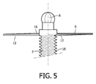
- Figure 5 shows the cutting member 9, as it is represented in figure 1 , in more detail.
- the threaded shaft 7 and the hexagonal coupling member 8 are represented in a side view, while the cutting member 9 is represented in a sectional view.
- the cutting member 9 extends in substantial radial direction of the threaded shaft 7.
- the upper side 16 and the lower side 17 of the cutting member 9 are curved helically, corresponding to the helical shape of the thread 18 of the threaded shaft 7.
- the cutting edge 12 borders the lower side 17 of the cutting member 9 and can be shaped by an angle of 90° or can be shaped as a sharp angle of the material of the cutting member 9.
- the cutting member 9 is attached to the threaded shaft 7 by a welding operation, by clamping, or by means of glue.
- any fixation means is possible, whereby the cutting member 9 can be permanently fixed to the threaded shaft 7, or whereby the cutting member 9 is removable from the threaded shaft 7.
- the shaft 7 is provided with a single helical thread, but it can also be a double helical thread, or there can be more threads in order to increase the pitch of the thread.
- the displacement of the lump of ice 10 in the container 1 per revolution of the threaded shaft 7 is proportional to the pith of the thread of the shaft 7.
- Figure 6 shows the ice dispensing device in a sectional view as is indicated with the arrows VI in figure 7.
- Figure 7 is the top view of the device represented in figure 6 .
- the device comprises the part 20 and the container 1, which container 1 is represented in figures 1 and 4 .
- the container 1 is attached up side down (as represented in figure 4 ) on the part 20, whereby the collar 13 of the container 1 is engaged by three engagement members 21 at the higher edge of part 20.
- the container 1 can be separated from the part 20 by rotating the container 1, so that the recesses 14 in the collar 13 correspond with the engagement members 21.
- Means for preventing the container 1 from rotating during the ice dispensing operation are present, but not represented in the figures.
- the parts of the container 1 are indicated with the same reference numerals as used in the figures 1-5 .
- the part 20 comprises an electric motor 22 having a drive shaft 23 carrying a coupling member 24 at its end.
- the coupling member 24 engages the corresponding hexagonal coupling member 8 (see figure 4 ) of the threaded shaft 7, so that the electric motor 22 drives through its drive shaft 23 the threaded shaft 7.
- the lump of ice 10 is shaved by the rotating cutting member 9 and falls down on the inclined surface 25 of the lower wall 26 of the ice receiving chamber 27.
- the drive shaft 23 of the electric motor 22 passes through an opening in said lower wall 26.
- the shaved pieces of ice slide over the inclined surface 25 to the ice dispensing opening 28 of the device.
- a glass with a drink can be put under the ice dispensing opening 28 in order to add ice to the drink.
- the described embodiment of the domestic ice dispensing device is only an example of a device according to the invention; many other embodiments are possible.
Landscapes
- Engineering & Computer Science (AREA)
- Physics & Mathematics (AREA)
- Mechanical Engineering (AREA)
- Thermal Sciences (AREA)
- General Engineering & Computer Science (AREA)
- Confectionery (AREA)
Abstract
A method and a device for making pieces of ice, whereby water in a container (1) is frozen into ice. A helically threaded shaft (7) extends through the container (1), so that the ice (10) surrounds the shaft (7) and is engaged by the helical thread (18) of the shaft (7). The threaded shaft (7) is rotated with respect to the ice (10), so that the ice (10) is moved toward a cutting member (9) carried by the threaded shaft (7). Thereby, the ice (10) is shaved by the cutting member (9).
Description
- The invention is related to a method for making pieces of ice, whereby water in a container is frozen into ice, whereby a helically threaded shaft extends through the container, so that ice surrounds the shaft and is engaged by the helical thread of the shaft, whereby the threaded shaft and/or the ice is rotated with respect to each other, so that the ice is moved in axial direction with respect to the shaft.
- Such method is disclosed in
US-A-3984996 . This publication describes an ice dispensing device, whereby a lump of ice is present in a tube like container having a square cross section. A threaded shaft extends in axial direction through the ice and the ice is moved through the container in said axial direction by rotating the threaded shaft. At the end of the tube like container is an ice cutting member, cutting uniform pieces of ice from the forward moving lump of ice (column of ice). - The pieces of ice can be put in a drink in order to cool the drink. The quantity of the dispensed ice is limited to one of the uniform pieces of ice or a certain number of such pieces of ice. It is not possible to add a desired quantity deviating from that to the drink. Furthermore, it may be desired to cool down the drink in a short time, and therefore the outer surface of the pieces of ice has to be relative large with respect to the content of the dispensed pieces of ice.
- A disadvantage of the device disclosed in
US-A-3984996 is that only pieces of ice having the same predetermined content can be produced, so that it is not possible to dispense any desired quantity of ice, for example a very small quantity. Furthermore, the dispensed pieces of ice are blocks, having a relative large content with respect to their outer surface, so that the pieces of ice will melt in a relative large period of time. - In particular, the ice dispensing device according to the invention is a domestic apparatus for delivering pieces of ice for many applications. The dispensed ice can be used for preparing food or for cooling objects or for adding ice to drinks.
- An object of the invention is a method and a device for making and dispensing pieces of ice, whereby a threaded shaft moves through a lump of ice by rotation with respect to the ice in order to move the ice toward an ice cutting member, whereby any quantity of ice can be dispensed, including very small quantities.
- Another object of the invention is a method and a device for making and dispensing pieces of ice, whereby a threaded shaft moves through a lump of ice by rotation with respect to the ice in order to move the ice toward an ice cutting member, whereby the dispensed pieces of ice has a large outer surface with respect to their content.
- To accomplish one or both these objects, the threaded shaft carries the cutting member being located at the surface of the ice, so that the ice and the cutting member moves toward each other by rotating the threaded shaft with respect to the ice, whereby the ice is shaved by the cutting member. Thereby relative thin pieces of ice (slices of ice) are removed from the lump of ice, having a relative large outer surface with respect to their content. Furthermore, the quantity of shaved ice is proportional to the angle of rotation of the threaded shaft, and therefore the dispensed ice can be dispensed exactly in any desired quantity, including in a very small quantity.
- The cutting member can be permanently fixed to the threaded shaft, but the cutting member can also be removably fixed to the shaft. The helical thread of the shaft can be a single helical thread, but it can also be a double helical thread, or there can be more threads, in other to increase the pitch of the thread, i.e. the distance of moving of the ice with respect to the shaft by each revolution of the shaft.
- In a preferred embodiment, the threaded shaft is mounted in the container with a side wall having an inner surface extending parallel to the axis of the threaded shaft, whereby the threaded shaft is rotated with respect to the container after the water is frozen into ice, so that the ice moves in the container in axial direction of the shaft, whereby the ice is prevented from rotating in the container by a non circular shape of the inner surface of the wall of the container in a cross section of said inner wall perpendicular to the axial direction. The cross sectional shape of the inner surface of the side wall of the container may be square or may have any other non circular shape, but preferably it has a substantial circular shape and comprises one or more ridges, or ribs, in axial direction.
- In a preferred embodiment, the container comprising the threaded shaft is, after it is filled with water, placed in a freezer, for example a domestic freezer, so that the water in the container freezes into ice, after which the container is attached to a structure having an electric motor, which electric motor drives rotationally the threaded shaft, whereby the shaved ice is guided to ice delivery means of the device. In particular, an electric motor is applied whereby the angle of rotation of the output shaft can be controlled. The ice dispensing device does not need to comprise cooling means, being an advantage, in particular for a domestic apparatus. The container can be insulated with heat insulating material and the device may comprise a relative small cooling device such as a Peltier element in order to keep the ice frozen. In another preferred embodiment, the ice dispensing device does not comprise powered cooling means, whereby the container is placed back in the freezer after use, so that the ice in the container is kept frozen.
- Preferably, the container comprises a bottom and is attached substantially up side down to the structure with the electric motor, whereby the cutting member is located at the lower side of the container. When the container is filled with water and placed in the freezer in upright position, the cutting member can be removed and the container can be closed with a cover. Preferably, the cutting member covers the major part of the upper side of the container and is provided with an opening, so that water can flow through the opening into the container. Thereby, the container can be placed in the freezer without an additional removable cover, and the cutting member can be permanently fixed to the threaded shaft.
- The invention is also related to an ice dispensing device for delivering pieces of ice, comprising a cutting member and a container for containing ice, whereby a rotating threaded shaft extends in axial direction through the space inside the container, and whereby the container has a surrounding side wall having an inner surface extending substantial parallel with the axial direction of the container, which inner surface has a non circular cross section perpendicular to said axial direction, whereby the threaded shaft carries the cutting member for shaving ice from the surface of the ice around the threaded shaft. Preferably, the inner surface of the side wall of the container is exactly parallel to the axial direction, but in another preferred embodiment, the inner surface of the side wall of the container diverges a little in the direction of the cutting member, preferably less than 0.1cm over its axial length. Thereby, the movability of the ice toward the cutting member can be improved.
- The cutting member may be shaped as a knife having a substantial radial cutting edge extending from the threaded shaft to the side wall of the container. Thereby, the cutting edge of the knife rests against the surface of the ice, and may be positioned under an angle with respect to said surface. Furthermore, the cutting member may have more than one cutting edge at different locations of the cutting member. However, in a preferred embodiment, the cutting member is a substantial disk-like element having a substantial straight cutting edge extending in substantial radial direction with respect to the threaded shaft, whereby the surface of the cutting member facing the ice is helically shaped corresponding to the helical shape of the thread of the shaft. The expression disk like means substantial flat and round. Thereby, the cutting member covers a substantial portion of opening of the container, and may have an opening for filling the container with water.
- The cross sectional shape of the inner wall of the container may have any shape, but in a preferred embodiment, the inner surface of the side wall of the container is substantial cylindrical and comprises one or more inwardly extending ridges in axial direction, so that the ice inside the container is prevented from rotating by the axial extending ridges or ribs.
- The ice dispensing device may comprise the described container and a handle that is, or can be, connected to the threaded shaft in order to rotate that shaft by hand. Thereby, the whole ice dispensing device can be placed in a freezer for freezing the water into ice and/or to keep its temperature low, whereby the handle for rotating the threaded shaft can be removed from the device, or can be permanently fixed to the threaded shaft.
- In a preferred embodiment, the device comprises an electric motor for driving the threaded shaft, whereby the container including the threaded shaft with the cutting member is removable from the part of the device comprising the electric motor, so that it can be filled with water and can be place in a freezer separated from the remainder part of the ice dispensing device. Thereby, the drive shaft of the electric motor is disconnectedly coupled with the threaded shaft in the container.
- In a preferred embodiment, the container has a bottom wall at its lower side opposite to its upper side where the cutting member is located, whereby the threaded shaft is rotatably fixed in said lower wall, and whereby the container, after water in it is frozen, can be placed up side down in the ice dispensing device. Up side down includes an inclined position of the container, i.e. that the axial direction of the container deviates from the vertical direction.
- Preferably, the bottom wall is provided with a valve in order to supply air in the container when the ice moves away from the bottom of the container by means of the rotating threaded shaft. Thereby, the movability of the ice in the container is improved.
- In a preferred embodiment, the material of the threaded shaft is flexible, so that the portion of the shaft near its driven end can rotate with respect to a portion further away from said driven end when the shaft is driven. Thereby, the rotational drive force is relative low when the ice sticks to the material of the threaded shaft. The flexible material of the shaft can be plastic, for example polypropylene.
- The invention will now be further elucidated by means of a description of an embodiment of a domestic ice dispensing device, whereby a rotating threaded shaft extends in axial direction through the space inside a container, whereby the threaded shaft carries a cutting member for shaving ice from the surface of the ice around the threaded shaft, whereby reference is made to the drawing comprising diagrammatical figures, whereby:
-
Fig. 1 is a sectional view of the container of the described embodiment; -
Fig. 2 is the top view of the container represented infigure 1 ; -
Fig. 3 is the bottom view of the container represented infigure 1 ; -
Fig. 4 is a sectional view of the container in up side down position; -
Fig. 5 shows the cutting member in more detail; -
Fig. 6 is a sectional view of the described embodiment; and -
Fig. 7 is the top view of the device represented infigure 6 . - The figures are very schematic representations, only showing parts that contribute to the elucidation of the described embodiment of the invention.
-
Figure 1 shows acontainer 1 for example made of molded plastic material such as polypropylene, and includes abottom wall 2. Theside wall 3 of thecontainer 1 has a cylindricalinner surface 4. Theside wall 3 comprise threeridges 5 extending in axial direction in thecontainer 1. Thebottom wall 2 comprises a valve, having avalve body 6 that can freely move in axial direction (vertical direction infigure 1 ). Infigure 1 , thevalve 6 is represented in closed position. Inside thecontainer 1 is a threadedshaft 7 extending in axial direction and supported in a central blind bore in thebottom wall 2. The threadedshaft 7 with the cuttingmember 9 can be removed from thecontainer 2, in order to fill the container with water. Furthermore, the separated parts can easily be cleaned. - The threaded
shaft 7 comprises at its upper end infigure 1 ahexagonal coupling member 8 in order to be engaged by drive means for rotating the threadedshaft 7. The threadedshaft 7 carries a cuttingmember 9 near its upper end infigure 1 . The cuttingmember 9 will be described in more detail hereinafter and is represented infigure 5 in more detail. Thecontainer 1 as shown infigure 1 can be filled with water and placed in a freezer so that the water is frozen into ice. After the water is frozen, the column or lump ofice 10 in thecontainer 1 can be moved in axial direction by rotating the threadedshaft 7. The helical thread ofshaft 7 may have any appropriate shape. -
Figure 2 shows the upper side of thecontainer 1 as represented infigure 1 , and the lower side of its representation infigure 4 . The sectional view offigure 1 is indicated with the arrows I infigure 2 . The cuttingmember 9 is substantially flat and disk like, and its surface directed to the inner space of thecontainer 1 is helical around the threadedshaft 7 corresponding to the helical thread of theshaft 7. The cuttingmember 9 has astraight cutting edge 12 extending in radial direction with respect to the threadedshaft 7. By rotating the threadedshaft 7, theice 10 is moved toward the cutting member 9 (downward infigure 4 ), while thecutting edge 12 shaves pieces of ice from the surface of theice 10.Figure 3 shows the lower side of thecontainer 1 as represented infigure 1 , and the upper side of its representation infigure 4 . The sectional view offigure 1 is indicated with the arrows I infigure 3 . -
Figure 4 shows the container in up side down position containing a column ofice 10 that is moved downward away from thebottom 2 by rotating theshaft 7. Thereby, thevalve 6 is open (shifted downward infigure 2 ), so that air can flow to thespace 11 between thebottom wall 2 and theice 10. By rotating the threadedshaft 7, the ice is pressed against the cuttingmember 9, which cuttingmember 9 shaves pieces or slices of ice from the lower surface of theice 10. - The
cylindrical side wall 3 of thecontainer 1 is provided with acollar 13 at its upper end. Thecollar 13 can be engaged by corresponding fixation means of the ice dispensing device, whereby parts of the fixation means can pass through the threerecesses 14 of thecollar 13. In front of thecutting edge 12 is anopening 15 having a substantial triangular shape. Through thisopening 15 thecontainer 1 can be filled with water when thecontainer 1 is in the upright position, as is shown infigure 1 . -
Figure 5 shows the cuttingmember 9, as it is represented infigure 1 , in more detail. The threadedshaft 7 and thehexagonal coupling member 8 are represented in a side view, while the cuttingmember 9 is represented in a sectional view. The cuttingmember 9 extends in substantial radial direction of the threadedshaft 7. Theupper side 16 and thelower side 17 of the cuttingmember 9 are curved helically, corresponding to the helical shape of thethread 18 of the threadedshaft 7. Thecutting edge 12 borders thelower side 17 of the cuttingmember 9 and can be shaped by an angle of 90° or can be shaped as a sharp angle of the material of the cuttingmember 9. - In the described embodiment, the cutting
member 9 is attached to the threadedshaft 7 by a welding operation, by clamping, or by means of glue. However, any fixation means is possible, whereby the cuttingmember 9 can be permanently fixed to the threadedshaft 7, or whereby the cuttingmember 9 is removable from the threadedshaft 7. In the described embodiment, theshaft 7 is provided with a single helical thread, but it can also be a double helical thread, or there can be more threads in order to increase the pitch of the thread. The displacement of the lump ofice 10 in thecontainer 1 per revolution of the threadedshaft 7 is proportional to the pith of the thread of theshaft 7. -
Figure 6 shows the ice dispensing device in a sectional view as is indicated with the arrows VI infigure 7. Figure 7 is the top view of the device represented infigure 6 . The device comprises thepart 20 and thecontainer 1, whichcontainer 1 is represented infigures 1 and4 . Thecontainer 1 is attached up side down (as represented infigure 4 ) on thepart 20, whereby thecollar 13 of thecontainer 1 is engaged by threeengagement members 21 at the higher edge ofpart 20. Thecontainer 1 can be separated from thepart 20 by rotating thecontainer 1, so that therecesses 14 in thecollar 13 correspond with theengagement members 21. Means for preventing thecontainer 1 from rotating during the ice dispensing operation are present, but not represented in the figures. - The parts of the
container 1 are indicated with the same reference numerals as used in thefigures 1-5 . Thepart 20 comprises anelectric motor 22 having adrive shaft 23 carrying a coupling member 24 at its end. The coupling member 24 engages the corresponding hexagonal coupling member 8 (seefigure 4 ) of the threadedshaft 7, so that theelectric motor 22 drives through itsdrive shaft 23 the threadedshaft 7. Thereby, the lump ofice 10 is shaved by the rotating cuttingmember 9 and falls down on theinclined surface 25 of thelower wall 26 of theice receiving chamber 27. Thedrive shaft 23 of theelectric motor 22 passes through an opening in saidlower wall 26. The shaved pieces of ice slide over theinclined surface 25 to theice dispensing opening 28 of the device. A glass with a drink can be put under theice dispensing opening 28 in order to add ice to the drink. - The described embodiment of the domestic ice dispensing device is only an example of a device according to the invention; many other embodiments are possible.
Claims (12)
- A method for making pieces of ice, whereby water in a container is frozen into ice, whereby a helically threaded shaft (7) extends through the container (1), so that ice (10) surrounds the shaft (7) and is engaged by the helical thread of the shaft (7), whereby the threaded shaft (7) and/or the ice (10) is rotated with respect to each other, so that the ice is moved in axial direction with respect to the shaft (7) toward a cutting member (9), characterized in that the threaded shaft (7) carries the cutting member (9) being located at the surface of the ice (10), so that the ice (10) and the cutting member (9) moves toward each other by rotating the threaded shaft (7) with respect to the ice (10), whereby the ice (10) is shaved by the cutting member (9).
- A method as claimed in claim 1, characterized in that the threaded shaft (7) is mounted in the container (1) with a side wall (3) having an inner surface (4) extending parallel to the axis of the threaded shaft (7), whereby the threaded shaft (7) is rotated with respect to the container (1) after the water is frozen into ice (10), so that the ice (10) moves in the container (1) in axial direction of the shaft (7), whereby the ice (10) is prevented from rotating in the container (1) by a non circular shape of the inner surface (4) of the wall (3) of the container (1) in a cross section of said inner wall (3) perpendicular to the axial direction.
- A method as claimed in any one of the preceding claims, characterized in that the container (1) comprising the threaded shaft (7) is, after it is filled with water, placed in a freezer so that the water in the container (1) freezes into ice (10), after which the container (1) is attached to a structure (20) having an electric motor (22), which electric motor (22) drives rotationally the threaded shaft (7), whereby the shaved ice is guided to ice delivery means (28) of the device.
- A method as claimed in claim 3, characterized in that the container (1) comprises a bottom (2) and is attached substantially up side down to said structure (20) with the electric motor (22), whereby the cutting member (9) is located at the lower side of the container (1).
- An ice dispensing device for delivering pieces of ice, comprising a cutting member (9) and a container (1) for containing ice (10), whereby a rotating threaded shaft (7) extends in axial direction through the space inside the container (1), and whereby the container (1) has a surrounding side wall (3) having an inner surface (4) extending substantial parallel with the axial direction of the container (1), which inner surface (4) has a non circular cross section perpendicular to said axial direction, characterized in that the threaded shaft (7) carries the cutting member (9) for shaving ice from the surface of the ice (10) around the threaded shaft (7).
- An ice dispensing device as claimed claim 5, characterized in that the inner surface (4) of the side wall (3) of the container (1) diverges a little in the direction of the cutting member (9), preferably less than 0.1cm over its axial length.
- An ice dispensing device as claimed in claim 5 or 6, characterized in that the cutting member (9) is a substantial disk-like element having a substantial straight cutting edge (12) extending in substantial radial direction with respect to the threaded shaft (7), whereby the surface (17) of the cutting member (9) facing the ice (10) is helically shaped corresponding to the helical shape of the thread (18) of the shaft (7).
- An ice dispensing device as claimed in any one of claims 5-7, characterized in that the inner surface (4) of the side wall (3) of the container (1) is substantial cylindrical and comprises one or more inwardly extending ridges (5) in axial direction.
- An ice dispensing device as claimed in any one of claims 5-8, comprising an electric motor (22) for driving the threaded shaft (7), characterized in that the container (1) including the threaded shaft (7) with the cutting member (9) is removable from the part (20) of the device comprising the electric motor (22).
- An ice dispensing device as claimed in any one of claims 5-9, characterized in that the container (1) has a bottom wall (2) at its lower side opposite to its upper side where the cutting member (9) is located, whereby the threaded shaft (7) is rotatably fixed in said lower wall (2), and whereby the container (1), after water in it is frozen, can be placed up side down in the ice dispensing device.
- An ice dispensing device as claimed in claim 10, characterized in that the bottom wall (2) is provided with a valve (6) in order to supply air in the container (1).
- An ice dispensing device as claimed in any one of claims 5-11, characterized in that the material of the threaded shaft (7) is flexible, so that the portion of the shaft (7) near its driven end can rotate with respect to a portion further away from said driven end.
Priority Applications (12)
| Application Number | Priority Date | Filing Date | Title |
|---|---|---|---|
| EP07119885A EP2056047A1 (en) | 2007-11-02 | 2007-11-02 | A method for making pieces of ice and an ice dispensing device |
| PCT/IB2008/054368 WO2009057017A1 (en) | 2007-11-02 | 2008-10-23 | A method of making pieces of ice and an ice dispensing device |
| RU2010122315/13A RU2478887C2 (en) | 2007-11-02 | 2008-10-23 | Method of making ice lumps and device to output ice |
| BRPI0819137A BRPI0819137A8 (en) | 2007-11-02 | 2008-10-23 | METHOD TO PRODUCE ICE PIECES AND ICE DISPENSER DEVICE |
| KR1020107011912A KR20100093547A (en) | 2007-11-02 | 2008-10-23 | A method of making pieces of ice and an ice dispensing device |
| CN2008801142676A CN101842649B (en) | 2007-11-02 | 2008-10-23 | A method of making pieces of ice and an ice dispensing device |
| AT08845216T ATE509244T1 (en) | 2007-11-02 | 2008-10-23 | METHOD FOR PRODUCING ICE PIECES AND ICE DISPENSING DEVICE |
| JP2010531612A JP5766949B2 (en) | 2007-11-02 | 2008-10-23 | Method of making ice pieces and ice dispensing device |
| EP20080845216 EP2208008B1 (en) | 2007-11-02 | 2008-10-23 | A method of making pieces of ice and an ice dispensing device |
| US12/739,418 US9121632B2 (en) | 2007-11-02 | 2008-10-23 | Method of making pieces of ice and an ice dispensing device |
| CN2008202074086U CN201440019U (en) | 2007-11-02 | 2008-10-29 | Ice distribution device |
| DE202008014427U DE202008014427U1 (en) | 2007-11-02 | 2008-10-30 | Device for producing pieces of ice and ice-cream dispensers |
Applications Claiming Priority (1)
| Application Number | Priority Date | Filing Date | Title |
|---|---|---|---|
| EP07119885A EP2056047A1 (en) | 2007-11-02 | 2007-11-02 | A method for making pieces of ice and an ice dispensing device |
Publications (1)
| Publication Number | Publication Date |
|---|---|
| EP2056047A1 true EP2056047A1 (en) | 2009-05-06 |
Family
ID=39301159
Family Applications (2)
| Application Number | Title | Priority Date | Filing Date |
|---|---|---|---|
| EP07119885A Ceased EP2056047A1 (en) | 2007-11-02 | 2007-11-02 | A method for making pieces of ice and an ice dispensing device |
| EP20080845216 Not-in-force EP2208008B1 (en) | 2007-11-02 | 2008-10-23 | A method of making pieces of ice and an ice dispensing device |
Family Applications After (1)
| Application Number | Title | Priority Date | Filing Date |
|---|---|---|---|
| EP20080845216 Not-in-force EP2208008B1 (en) | 2007-11-02 | 2008-10-23 | A method of making pieces of ice and an ice dispensing device |
Country Status (10)
| Country | Link |
|---|---|
| US (1) | US9121632B2 (en) |
| EP (2) | EP2056047A1 (en) |
| JP (1) | JP5766949B2 (en) |
| KR (1) | KR20100093547A (en) |
| CN (2) | CN101842649B (en) |
| AT (1) | ATE509244T1 (en) |
| BR (1) | BRPI0819137A8 (en) |
| DE (1) | DE202008014427U1 (en) |
| RU (1) | RU2478887C2 (en) |
| WO (1) | WO2009057017A1 (en) |
Cited By (1)
| Publication number | Priority date | Publication date | Assignee | Title |
|---|---|---|---|---|
| CN102770726A (en) * | 2010-02-23 | 2012-11-07 | Lg电子株式会社 | Ice maker, refrigerator having the same, and method for supplying ice thereof |
Families Citing this family (9)
| Publication number | Priority date | Publication date | Assignee | Title |
|---|---|---|---|---|
| EP2056047A1 (en) | 2007-11-02 | 2009-05-06 | Koninklijke Philips Electronics N.V. | A method for making pieces of ice and an ice dispensing device |
| RU2473850C1 (en) * | 2011-06-23 | 2013-01-27 | Учреждение Российской академии наук Институт криосферы Земли Сибирского отделения РАН (ИКЗ СО РАН) | Method of ice dispersion |
| CN103471304B (en) * | 2013-08-22 | 2015-06-24 | 独孤勇 | Pipeline switching ice conveying device and control method thereof |
| ES1103105Y (en) * | 2014-01-10 | 2014-06-05 | Abr Ingenieros S L | IMPROVED ICE CUTTING MACHINE |
| RU2652658C1 (en) * | 2017-04-10 | 2018-04-28 | Федеральное государственное унитарное предприятие "Центральный институт авиационного моторостроения имени П.И. Баранова" | Pneumatic device for shock test of an aircraft engine design |
| CN107964916B (en) * | 2017-12-05 | 2024-08-13 | 中国电建集团贵阳勘测设计研究院有限公司 | Method and device for preventing hydropower station storage area equipment from icing |
| RU2683518C1 (en) * | 2018-04-05 | 2019-03-28 | Федеральное государственное бюджетное образовательное учреждение высшего образования "Уральский государственный экономический университет" (УрГЭУ) | Cooked sausages storage life extension method |
| WO2020006577A1 (en) * | 2018-06-29 | 2020-01-02 | Snowie LLC | Ice shaving machine |
| CN112944761B (en) * | 2021-02-19 | 2022-06-21 | 哈尔滨工程大学 | Finish machining device for cylindrical ice test piece |
Citations (5)
| Publication number | Priority date | Publication date | Assignee | Title |
|---|---|---|---|---|
| GB695696A (en) * | 1952-05-19 | 1953-08-12 | Svenska Turbinfab Ab | Improved ice making machine |
| US3984996A (en) * | 1975-04-02 | 1976-10-12 | General Motors Corporation | Vertical tube ice maker |
| US6082121A (en) * | 1999-04-02 | 2000-07-04 | Group Dekko Services, Llc. | Ice maker |
| US20020007638A1 (en) * | 1999-04-02 | 2002-01-24 | Andrei Tchougounov | Ice maker and method of making ice |
| EP1710520A2 (en) * | 2005-03-15 | 2006-10-11 | Whirlpool Corporation | Mechanism for dispensing shaved ice from a refrigeration appliance |
Family Cites Families (41)
| Publication number | Priority date | Publication date | Assignee | Title |
|---|---|---|---|---|
| US380177A (en) * | 1888-03-27 | David beown | ||
| US1722031A (en) * | 1927-05-31 | 1929-07-23 | Bert Samuel | Ice-shaving machine |
| US1779341A (en) * | 1929-12-27 | 1930-10-21 | Benjamen F Stieber | Butter slicer and container |
| US1992783A (en) * | 1931-02-03 | 1935-02-26 | Ralston R Smith | Ice shaving machine |
| US2122947A (en) * | 1936-05-04 | 1938-07-05 | David C Lopez | Slicing and dispensing device |
| US2191756A (en) * | 1939-07-17 | 1940-02-27 | Albert C Gray | Ice shaving machine |
| US2453140A (en) * | 1943-12-28 | 1948-11-09 | Vogt & Co Inc Henry | Adjustable cutter for tube-ice machines |
| US2477474A (en) * | 1948-04-12 | 1949-07-26 | Bert Samuel | Ice shaving machine |
| US2655318A (en) * | 1950-06-29 | 1953-10-13 | Herbert G Beyer | Ice shaving machine |
| US2757909A (en) * | 1953-04-29 | 1956-08-07 | Birtman Electric Co | Agitator device for a mixer |
| US2751118A (en) * | 1954-11-12 | 1956-06-19 | Charles W Soule | Spread dispenser |
| US2853243A (en) * | 1954-11-15 | 1958-09-23 | Bert Samuel | Ice shaving machine |
| US3274792A (en) * | 1965-09-16 | 1966-09-27 | Remcor Prod Co | Icemaker with piston-type ice remover |
| SE307149B (en) * | 1967-03-17 | 1968-12-23 | Stal Refrigeration Ab | |
| US3552663A (en) * | 1968-12-05 | 1971-01-05 | John Royals | Ice shaving machine |
| JPS4714473Y1 (en) * | 1969-09-10 | 1972-05-24 | ||
| US4113190A (en) * | 1976-05-20 | 1978-09-12 | Israel Fudman | Device for shaving ice |
| US4123918A (en) * | 1976-12-09 | 1978-11-07 | King-Seeley Thermos Co. | Ice dispensing machine |
| JPS563588Y2 (en) * | 1976-12-30 | 1981-01-26 | ||
| JPS56170671U (en) * | 1980-05-19 | 1981-12-16 | ||
| US4484455A (en) * | 1983-01-14 | 1984-11-27 | Hoshizaki Electric Co., Ltd. | Cutter for an auger type icemaker |
| US4621968A (en) | 1984-01-03 | 1986-11-11 | Tiger Industries, Inc. | Segmented auger conveyor |
| US4569266A (en) * | 1984-07-23 | 1986-02-11 | Chubu Industries, Inc. | Food-cutting apparatus |
| US4718610A (en) * | 1985-09-17 | 1988-01-12 | Gallaher Harold D | Ice shaver |
| US4681030C1 (en) * | 1986-02-20 | 2001-05-08 | Hmc Of Massachusetts Ltd Partn | Apparatus for preparing frozen drinks |
| US4796784A (en) * | 1987-07-02 | 1989-01-10 | G & S Metal Product Company, Inc. | Soft ice cream dispenser |
| US5620115A (en) * | 1987-12-10 | 1997-04-15 | Mcgill; Shane R. | Confection dispensing apparatus |
| US4998677A (en) * | 1988-04-13 | 1991-03-12 | Gallaher Harold D | Machine for shaving ice |
| JP2614500B2 (en) * | 1988-11-02 | 1997-05-28 | 三洋電機株式会社 | Ice machine |
| US5191772A (en) * | 1992-02-13 | 1993-03-09 | Pacific Rockies, Inc. | Auger-type ice-making apparatus |
| CN2165386Y (en) * | 1993-06-15 | 1994-05-18 | 王育郎 | Continuous internal and external spiral ice making device |
| US5325682A (en) * | 1993-08-18 | 1994-07-05 | Chiang Sen Mu | Water distributor and ice cutter for a tube-ice machine |
| US5402949A (en) * | 1993-11-30 | 1995-04-04 | Richard D. Ipsen | Ice shaving apparatus |
| US5513810A (en) * | 1995-05-17 | 1996-05-07 | Shing-Pun Enterprise Co., Ltd. | Thickness adjuster for an ice shaver |
| US6012660A (en) * | 1997-12-02 | 2000-01-11 | Vaansinn Products, Inc. | Rotary ice shaving machine |
| US6389836B1 (en) * | 2000-06-08 | 2002-05-21 | The Little Tikes Company | Ice mill for use with toy refreshment stand |
| DE10220792A1 (en) * | 2002-05-10 | 2003-11-20 | Azo Verwaltungs Gmbh | Device for allocating flowable materials |
| US7074452B2 (en) * | 2003-06-21 | 2006-07-11 | Gary Lebowitz | Method and apparatus for individual frozen beverage mold and dispenser |
| US7325413B2 (en) * | 2003-12-18 | 2008-02-05 | Conair Corporation | Apparatus for making ice cream having an improved dispenser |
| US20050158427A1 (en) * | 2004-01-15 | 2005-07-21 | Sierra Innotek, Inc. | Means and device for decorating food items |
| EP2056047A1 (en) * | 2007-11-02 | 2009-05-06 | Koninklijke Philips Electronics N.V. | A method for making pieces of ice and an ice dispensing device |
-
2007
- 2007-11-02 EP EP07119885A patent/EP2056047A1/en not_active Ceased
-
2008
- 2008-10-23 JP JP2010531612A patent/JP5766949B2/en not_active Expired - Fee Related
- 2008-10-23 AT AT08845216T patent/ATE509244T1/en not_active IP Right Cessation
- 2008-10-23 EP EP20080845216 patent/EP2208008B1/en not_active Not-in-force
- 2008-10-23 US US12/739,418 patent/US9121632B2/en not_active Expired - Fee Related
- 2008-10-23 CN CN2008801142676A patent/CN101842649B/en not_active Expired - Fee Related
- 2008-10-23 WO PCT/IB2008/054368 patent/WO2009057017A1/en not_active Ceased
- 2008-10-23 KR KR1020107011912A patent/KR20100093547A/en not_active Withdrawn
- 2008-10-23 RU RU2010122315/13A patent/RU2478887C2/en not_active IP Right Cessation
- 2008-10-23 BR BRPI0819137A patent/BRPI0819137A8/en not_active IP Right Cessation
- 2008-10-29 CN CN2008202074086U patent/CN201440019U/en not_active Expired - Lifetime
- 2008-10-30 DE DE202008014427U patent/DE202008014427U1/en not_active Expired - Lifetime
Patent Citations (5)
| Publication number | Priority date | Publication date | Assignee | Title |
|---|---|---|---|---|
| GB695696A (en) * | 1952-05-19 | 1953-08-12 | Svenska Turbinfab Ab | Improved ice making machine |
| US3984996A (en) * | 1975-04-02 | 1976-10-12 | General Motors Corporation | Vertical tube ice maker |
| US6082121A (en) * | 1999-04-02 | 2000-07-04 | Group Dekko Services, Llc. | Ice maker |
| US20020007638A1 (en) * | 1999-04-02 | 2002-01-24 | Andrei Tchougounov | Ice maker and method of making ice |
| EP1710520A2 (en) * | 2005-03-15 | 2006-10-11 | Whirlpool Corporation | Mechanism for dispensing shaved ice from a refrigeration appliance |
Cited By (4)
| Publication number | Priority date | Publication date | Assignee | Title |
|---|---|---|---|---|
| CN102770726A (en) * | 2010-02-23 | 2012-11-07 | Lg电子株式会社 | Ice maker, refrigerator having the same, and method for supplying ice thereof |
| CN102770726B (en) * | 2010-02-23 | 2015-07-15 | Lg电子株式会社 | Ice maker, refrigerator having the same, and method for supplying ice thereof |
| EP2539647A4 (en) * | 2010-02-23 | 2016-02-17 | Lg Electronics Inc | Ice maker, refrigerator having the same, and method for supplying ice thereof |
| US9494357B2 (en) | 2010-02-23 | 2016-11-15 | Lg Electronics Inc. | Ice maker, refrigerator having the same, and method for supplying ice thereof |
Also Published As
| Publication number | Publication date |
|---|---|
| EP2208008B1 (en) | 2011-05-11 |
| CN201440019U (en) | 2010-04-21 |
| RU2010122315A (en) | 2011-12-10 |
| KR20100093547A (en) | 2010-08-25 |
| BRPI0819137A2 (en) | 2009-05-07 |
| CN101842649B (en) | 2012-09-05 |
| RU2478887C2 (en) | 2013-04-10 |
| BRPI0819137A8 (en) | 2016-02-10 |
| US9121632B2 (en) | 2015-09-01 |
| US20100257874A1 (en) | 2010-10-14 |
| ATE509244T1 (en) | 2011-05-15 |
| WO2009057017A1 (en) | 2009-05-07 |
| DE202008014427U1 (en) | 2009-02-19 |
| JP5766949B2 (en) | 2015-08-19 |
| EP2208008A1 (en) | 2010-07-21 |
| JP2011503499A (en) | 2011-01-27 |
| CN101842649A (en) | 2010-09-22 |
Similar Documents
| Publication | Publication Date | Title |
|---|---|---|
| EP2208008B1 (en) | A method of making pieces of ice and an ice dispensing device | |
| US6863916B2 (en) | Apparatus and methods for making frozen food products | |
| US6527212B2 (en) | Ice shaver | |
| US7278275B2 (en) | Mechanism for dispensing shaved ice from a refrigeration appliance | |
| US4653281A (en) | Drink making method and apparatus | |
| US7178976B2 (en) | Blender for ingredients into soft-serve freezer products | |
| US20240210088A1 (en) | Ice shaving machine | |
| CA2031381A1 (en) | Ice dispenser conveying means | |
| US9894912B2 (en) | Chilled product post-processing apparatus | |
| US20090186141A1 (en) | Method for blending a beverage in a single serving cup | |
| CN106998722A (en) | Apparatus and method for handling food cream | |
| EP2876388B1 (en) | Ice bin and method of crushing ice using the same | |
| US4796784A (en) | Soft ice cream dispenser | |
| CA2471482A1 (en) | Slush beverage maker | |
| CN113226047A (en) | System for delivering frozen or chilled beverages | |
| US4732006A (en) | Icemakers and methods of making ice | |
| US20110309106A1 (en) | Apparatus and methods for portioning and dispensing a frozen product | |
| KR100603831B1 (en) | Electric Ice Cream Dishwasher | |
| HK1246091B (en) | Chilled product post-processing apparatus |
Legal Events
| Date | Code | Title | Description |
|---|---|---|---|
| PUAI | Public reference made under article 153(3) epc to a published international application that has entered the european phase |
Free format text: ORIGINAL CODE: 0009012 |
|
| AK | Designated contracting states |
Kind code of ref document: A1 Designated state(s): AT BE BG CH CY CZ DE DK EE ES FI FR GB GR HU IE IS IT LI LT LU LV MC MT NL PL PT RO SE SI SK TR |
|
| AX | Request for extension of the european patent |
Extension state: AL BA HR MK RS |
|
| STAA | Information on the status of an ep patent application or granted ep patent |
Free format text: STATUS: THE APPLICATION HAS BEEN REFUSED |
|
| 18R | Application refused |
Effective date: 20090524 |