EP2056041A1 - Heat transfer device - Google Patents
Heat transfer device Download PDFInfo
- Publication number
- EP2056041A1 EP2056041A1 EP08721283A EP08721283A EP2056041A1 EP 2056041 A1 EP2056041 A1 EP 2056041A1 EP 08721283 A EP08721283 A EP 08721283A EP 08721283 A EP08721283 A EP 08721283A EP 2056041 A1 EP2056041 A1 EP 2056041A1
- Authority
- EP
- European Patent Office
- Prior art keywords
- refrigerant
- heat exchanger
- channel
- side heat
- transfer device
- Prior art date
- Legal status (The legal status is an assumption and is not a legal conclusion. Google has not performed a legal analysis and makes no representation as to the accuracy of the status listed.)
- Withdrawn
Links
Images





Classifications
-
- F—MECHANICAL ENGINEERING; LIGHTING; HEATING; WEAPONS; BLASTING
- F25—REFRIGERATION OR COOLING; COMBINED HEATING AND REFRIGERATION SYSTEMS; HEAT PUMP SYSTEMS; MANUFACTURE OR STORAGE OF ICE; LIQUEFACTION SOLIDIFICATION OF GASES
- F25B—REFRIGERATION MACHINES, PLANTS OR SYSTEMS; COMBINED HEATING AND REFRIGERATION SYSTEMS; HEAT PUMP SYSTEMS
- F25B9/00—Compression machines, plants or systems, in which the refrigerant is air or other gas of low boiling point
- F25B9/002—Compression machines, plants or systems, in which the refrigerant is air or other gas of low boiling point characterised by the refrigerant
- F25B9/008—Compression machines, plants or systems, in which the refrigerant is air or other gas of low boiling point characterised by the refrigerant the refrigerant being carbon dioxide
-
- F—MECHANICAL ENGINEERING; LIGHTING; HEATING; WEAPONS; BLASTING
- F25—REFRIGERATION OR COOLING; COMBINED HEATING AND REFRIGERATION SYSTEMS; HEAT PUMP SYSTEMS; MANUFACTURE OR STORAGE OF ICE; LIQUEFACTION SOLIDIFICATION OF GASES
- F25B—REFRIGERATION MACHINES, PLANTS OR SYSTEMS; COMBINED HEATING AND REFRIGERATION SYSTEMS; HEAT PUMP SYSTEMS
- F25B23/00—Machines, plants or systems, with a single mode of operation not covered by groups F25B1/00 - F25B21/00, e.g. using selective radiation effect
-
- F—MECHANICAL ENGINEERING; LIGHTING; HEATING; WEAPONS; BLASTING
- F25—REFRIGERATION OR COOLING; COMBINED HEATING AND REFRIGERATION SYSTEMS; HEAT PUMP SYSTEMS; MANUFACTURE OR STORAGE OF ICE; LIQUEFACTION SOLIDIFICATION OF GASES
- F25B—REFRIGERATION MACHINES, PLANTS OR SYSTEMS; COMBINED HEATING AND REFRIGERATION SYSTEMS; HEAT PUMP SYSTEMS
- F25B13/00—Compression machines, plants or systems, with reversible cycle
-
- F—MECHANICAL ENGINEERING; LIGHTING; HEATING; WEAPONS; BLASTING
- F25—REFRIGERATION OR COOLING; COMBINED HEATING AND REFRIGERATION SYSTEMS; HEAT PUMP SYSTEMS; MANUFACTURE OR STORAGE OF ICE; LIQUEFACTION SOLIDIFICATION OF GASES
- F25B—REFRIGERATION MACHINES, PLANTS OR SYSTEMS; COMBINED HEATING AND REFRIGERATION SYSTEMS; HEAT PUMP SYSTEMS
- F25B2309/00—Gas cycle refrigeration machines
- F25B2309/06—Compression machines, plants or systems characterised by the refrigerant being carbon dioxide
- F25B2309/061—Compression machines, plants or systems characterised by the refrigerant being carbon dioxide with cycle highest pressure above the supercritical pressure
-
- F—MECHANICAL ENGINEERING; LIGHTING; HEATING; WEAPONS; BLASTING
- F25—REFRIGERATION OR COOLING; COMBINED HEATING AND REFRIGERATION SYSTEMS; HEAT PUMP SYSTEMS; MANUFACTURE OR STORAGE OF ICE; LIQUEFACTION SOLIDIFICATION OF GASES
- F25B—REFRIGERATION MACHINES, PLANTS OR SYSTEMS; COMBINED HEATING AND REFRIGERATION SYSTEMS; HEAT PUMP SYSTEMS
- F25B2400/00—Component parts or details not otherwise provided for in this subclass
- F25B2400/16—Receivers
Definitions
- the present invention is achieved in view of these technical problems, and has an object to provide a heat transfer device that can adjust a difference between an amount of refrigerant in heating operation and that in cooling operation when CO 2 is used as a refrigerant, without separately providing a heater and a cooler.
- the liquid pump 1 is provided on the pipe L1 (first channel) connecting the heat source side heat exchanger 2 and the use side heat exchanger 4.
- the gas refrigerant Among refrigerants in a gas-liquid separation state stored in the refrigerant tank 3, the gas refrigerant only is supplied through the pipe L31 with the second electromagnetic valve 6 opened and the pipe L2 to the heat source side heat exchanger 2.
- the gas refrigerant supplied to the heat source side heat exchanger 2 radiates heat by heat exchange with a cold source, is condensed and liquefied, and returns to the liquid pump 1.
- the third electromagnetic valve 7 can be opened (ON) to flow the part of the liquid refrigerant discharged from the liquid pump 1 through the pipe L4 into the refrigerant tank 3, but an excessive amount of refrigerant flowing into the refrigerant tank 3 reduces the pressure of the refrigerant in the heat transfer circuit.
- the fifth electromagnetic valve 9 is opened. Then, the liquid refrigerant stored in the refrigerant tank 3 flows through the pipe L5 into the pipe L2. The liquid refrigerant is supplied to the heat source side heat exchanger 2 together with the gas refrigerant flowing through the pipe L31 to the pipe L2 in a gas-liquid two phase mixed state.
Landscapes
- Engineering & Computer Science (AREA)
- Physics & Mathematics (AREA)
- Mechanical Engineering (AREA)
- Thermal Sciences (AREA)
- General Engineering & Computer Science (AREA)
- Chemical & Material Sciences (AREA)
- Chemical Kinetics & Catalysis (AREA)
- Other Air-Conditioning Systems (AREA)
- Cooling Or The Like Of Electrical Apparatus (AREA)
- Compression-Type Refrigeration Machines With Reversible Cycles (AREA)
- Air Conditioning Control Device (AREA)
Abstract
Description
- The present invention relates to a heat transfer device for transferring heat using a refrigerant that undergoes a gas-liquid phase change, and more particularly to a heat transfer device suitable when using carbon dioxide (CO2) as a refrigerant.
- A conventionally known secondary refrigerant type air conditioner is disclosed in
Patent Document 1. The air conditioner inPatent Document 1 is based on using a high pressure refrigerant such as R-410A. The air conditioner includes, as shown inFigure 9 , aprimary side circuit 111 including abypass circuit 109 in which abypass valve 107 is provided between apressure reducing device 104 that constitutes an outdoor unit and a four-way valve 102, and anoutdoor heat exchanger 103, asecondary side circuit 112 that supplies a refrigerant subjected to heat exchange with a refrigerant in theprimary side circuit 111 to anindoor heat exchanger 105 using apump 108 in the circuit, and aplate heat exchanger 106 that introduces the refrigerants in theprimary side circuit 111 and thesecondary side circuit 112 and changing a refrigerant temperature in thesecondary side circuit 112 to a desired indoor temperature. The air conditioner can use an existing indoor unit and connection pipe having low pressure resistance and can pass environmental regulation. - As one of CFC reduction measures of a refrigerant, use of CO2 as a working gas (refrigerant) has been made and considered. For the air conditioner disclosed in
Patent Document 1 using CO2 as a refrigerant, an amount of refrigerant required in heating operation is considerably different from that required in cooling operation. Specifically, heating operation is performed at supercritical pressure, while cooling operation is performed at critical pressure or lower. Thus, a density of the refrigerant is high in heating operation, while the density is low in cooling operation because of existence of a two-phase region and a gas region. By one estimate, the density in heating operation is two or three times the density in cooling operation. Thus, if the amount of refrigerant is set to an appropriate amount in heating operation, an excess of refrigerant is produced in cooling operation. - Patent Document 1: Japanese Patent Laid-open No.
2001-241800 Figure 1 ) - Patent Document 2: Japanese Patent Laid-open No.
5-231730 - In the air conditioner disclosed in
Patent Document 1, a mechanism that adjusts the difference in the amount of refrigerant is not provided and transfer pressure is automatically determined, and thus the heating operation and the cooling operation are incompatible. -
Patent Document 2 discloses a method of adjusting an amount of refrigerant by providing a refrigerant tank on a refrigerant pipe. However,Patent Document 2 requires a heater and a cooler for flowing the refrigerant into and out of the refrigerant tank, thereby increasing production cost of a heat transfer device and requiring electric power cost for heating and cooling in operation of an air conditioner. - The present invention is achieved in view of these technical problems, and has an object to provide a heat transfer device that can adjust a difference between an amount of refrigerant in heating operation and that in cooling operation when CO2 is used as a refrigerant, without separately providing a heater and a cooler.
- To achieve the above described object, the present invention provides a heat transfer device including: a heat source side heat exchanger that performs heat exchange between a refrigerant that accompanies a gas-liquid phase change and a cold source or a hot source; a use side heat exchanger that receives the refrigerant subjected to the heat exchange in the heat source side heat exchanger and uses cold or heat; a transfer pump that discharges the refrigerant toward the heat source side heat exchanger or the use side heat exchanger; a first channel that connects the heat source side heat exchanger, the transfer pump, and the use side heat exchanger, and through which the refrigerant discharged from the transfer pump flows toward the heat source side heat exchanger or the use side heat exchanger; a second channel that connects the heat source side heat exchanger and the use side heat exchanger, and through which the refrigerant flowing out of the heat source side heat exchanger flows toward the use side heat exchanger or through which the refrigerant flowing out of the use side heat exchanger flows toward the heat source side heat exchanger; a third channel that is provided in parallel with the second channel and has one end communicating with the side closer to the heat source side heat exchanger and the other end communicating with the side closer to the use side heat exchanger; a refrigerant tank provided on the third channel; and a fourth channel that has one end communicating with the first channel between the transfer pump and the use side heat exchanger and the other end communicating with the refrigerant tank.
- In the heat transfer device, in cooling operation, a heat transfer circuit is configured in which the refrigerant discharged from the transfer pump passes through the use side heat exchanger, the refrigerant tank, and the heat source side heat exchanger in this order and is returned to the transfer pump. In cooling operation, a part of the refrigerant in liquid form (liquid refrigerant) discharged from the transfer pump is flown through the fourth channel into the refrigerant tank and stored. The part of the refrigerant is an excess of refrigerant. The part of the refrigerant can be flown into the refrigerant tank by discharge pressure of the transfer pump.
- In heating operation, a heat transfer circuit is configured in which the refrigerant discharged from the transfer pump passes through the heat source side heat exchanger and the use side heat exchanger in this order and is returned to the transfer pump.
- In the heat transfer device of the present invention, the liquid refrigerant stored in the refrigerant tank needs to be returned to the heat transfer circuit in switching from cooling operation to heating operation. This is for ensuring an amount of refrigerant required for heating operation. Thus, in the heat transfer device of the present invention, in switching from cooling operation to heating operation, the refrigerant in gas form that undergoes heat absorption in the heat source side heat exchanger is flown through the second channel and the third channel into the refrigerant tank. This increases pressure in the refrigerant tank. Thus, the liquid refrigerant stored in the refrigerant tank can be flown through the fourth channel to the first channel. After the refrigerant stored in the refrigerant tank is thus returned to the heat transfer circuit, the heat transfer device of the present invention can start heating operation.
- In the heat transfer device of the present invention, the liquid refrigerant is stored in the refrigerant tank in cooling operation, and it should be supposed that the refrigerant is excessively stored. Thus, the heat transfer device of the present invention preferably includes a mechanism that quickly returns the liquid refrigerant stored in the refrigerant tank to the heat transfer circuit in the above described case. Thus, the present invention includes a fifth channel that has one end communicating with the refrigerant tank and the other end communicating with the second channel between a point in the third channel communicating with the side closer to the heat source side heat exchanger and the heat source side heat exchanger. Then, when the liquid refrigerant stored in the refrigerant tank exceeds a predetermined amount, that is, the liquid refrigerant is excessively stored, the liquid refrigerant can be returned through the fifth channel to the second channel.
- In the heat transfer device of the present invention, the liquid refrigerant is preferably supplied to the transfer pump at the start of cooling operation. This is for ensuring startability of the transfer pump. However, it is supposed that the liquid refrigerant is insufficiently supplied to the transfer pump at the start of cooling operation. Thus, the present invention includes a mechanism that can quickly supply the liquid refrigerant stored in the refrigerant tank to the transfer pump. Thus, the heat transfer device of the present invention includes a sixth channel that has one end communicating with the refrigerant tank and the other end communicating with the first channel between the heat source side heat exchanger and the transfer pump. Then, the refrigerant in liquid form stored in the refrigerant tank can be returned through the sixth channel to the first channel at the start of cooling operation.
- In the heat transfer device of the present invention, the first channel preferably has a region in which the channel is located in a higher position than an upper end of the refrigerant tank between a point communicating with the fourth channel and the use side heat exchanger. Thus, when the liquid refrigerant stored in the refrigerant tank flows out to the fourth channel, the liquid refrigerant can be flown toward the transfer pump rather than the use side heat exchanger. The liquid refrigerant is collected near the transfer pump for ensuring startability of the transfer pump.
- The heat transfer device of the present invention is particularly effective when the refrigerant is carbon dioxide (CO2). When the refrigerant is carbon dioxide (CO2), the heat transfer is performed at critical pressure or lower in cooling operation, while the heat transfer is performed at supercritical pressure in heating operation, and there is a big difference between the amounts of refrigerant in the operations.
- As described above, according to the present invention, the part of the refrigerant discharged from the transfer pump can be flown into the refrigerant tank and stored in cooling operation. Specifically, in cooling operation, an excess of refrigerant can be removed from the heat transfer circuit to perform cooling operation with an appropriate amount of refrigerant. In heating operation, the refrigerant stored in the refrigerant tank can be returned to the heat transfer circuit to perform heating operation with an appropriate amount of refrigerant. Further, the part of the refrigerant can be stored in the refrigerant tank and the refrigerant stored in the refrigerant tank can be returned to the heat transfer circuit without separately providing a heater and a cooler. This prevents an increase in production cost of the heat transfer device and requires no electric power cost for heating and cooling in operation of the heat transfer device.
-
-
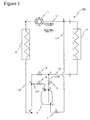
Figure 1 is a circuit diagram of a heat transfer device according to a first embodiment of the present invention; -
Figure 2 three-dimensionally shows a circuit of the heat transfer device according to the first embodiment of the present invention; -
Figure 3 is a circuit diagram of the heat transfer device according to the first embodiment of the present invention and shows a flow of a refrigerant in cooling operation; -
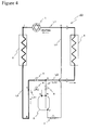
Figure 4 is a circuit diagram of the heat transfer device according to the first embodiment of the present invention and shows a flow of the refrigerant in heating operation; -
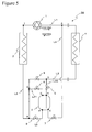
Figure 5 is a circuit diagram of a heat transfer device according to a second embodiment of the present invention; -
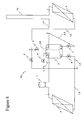
Figure 6 is a circuit diagram of a heat transfer device according to a third embodiment of the present invention; -
Figure 7 is a circuit diagram of a heat transfer device according to a fourth embodiment of the present invention; -
Figure 8 three-dimensionally shows a circuit of the heat transfer device according to the fourth embodiment of the present invention; and -
Figure 9 is a circuit diagram of a conventional air conditioner. -
- 1
- liquid pump
- 2
- heat source side heat exchanger
- 3
- refrigerant tank
- 4
- use side heat exchanger
- 5
- first electromagnetic valve
- 6
- second electromagnetic valve
- 7
- third electromagnetic valve
- 8
- fourth electromagnetic valve
- 9
- fifth electromagnetic valve
- 10
- sixth electromagnetic valve
- 11
- trap
- 20, 30, 40, 50
- heat transfer device
- L1 to L6
- pipe
- Now, the present invention will be described in detail on the basis of embodiments shown in the accompanying drawings.
-
Figure 1 is a circuit diagram showing a configuration of aheat transfer device 20 according to a first embodiment of the present invention.Figure 2 three-dimensionally shows a circuit showing the configuration of theheat transfer device 20. Thus,Figure 2 can identify a positional relationship between components that constitute theheat transfer device 20. - As shown in
Figures 1 and2 , in theheat transfer device 20, aliquid pump 1 that is a transfer pump, a heat sourceside heat exchanger 2, arefrigerant tank 3, and a useside heat exchanger 4 are connected in this order by pipes L1 to L4 and constitute a closed circuit. In the closed circuit, a refrigerant that undergoes a gas-liquid phase change, typically, CO2 is sealed. Theheat transfer device 20 transfers the refrigerant (CO2, hereinafter simply referred to as refrigerant) at supercritical pressure in heating operation, transfers the refrigerant at critical pressure or lower in cooling operation, and performs heat exchange with a phase change between the heat sourceside heat exchanger 2 and the useside heat exchanger 4. A more detailed configuration of theheat transfer device 20 will be described below. - The
liquid pump 1 is provided on the pipe L1 (first channel) connecting the heat sourceside heat exchanger 2 and the useside heat exchanger 4. - The pipe L2 (second channel) connecting the heat source
side heat exchanger 2 and the useside heat exchanger 4 is provided. From the pipe L2, a pipe L31 (third channel) branches off at a point C and a pipe L32 (third channel) branches off at a point D. - The pipe L31 has one end passing through an upper portion (point G) of the
refrigerant tank 3 and communicating with the inside of therefrigerant tank 3. A secondelectromagnetic valve 6 is provided on the pipe L31. Specifically, the heat sourceside heat exchanger 2 and therefrigerant tank 3 are connected via the secondelectromagnetic valve 6. - The pipe L32 has one end passing through an upper portion (point H) of the
refrigerant tank 3, extending to a lower portion of therefrigerant tank 3, and communicating with the inside of therefrigerant tank 3. A firstelectromagnetic valve 5 is provided between the points D and H on the pipe L32. - A fourth
electromagnetic valve 8 is provided between the points C and D on the pipe L2. - From the pipe L1, a pipe L4 (fourth channel) branches off at a point A between the
liquid pump 1 and the useside heat exchanger 4. The point A is on a discharge side of theliquid pump 1 in cooling operation. The other end of the pipe L4 communicates with the inside of therefrigerant tank 3 at a lower end (point E) of therefrigerant tank 3. A thirdelectromagnetic valve 7 is provided on the pipe L4. The point A is in a lower position than the point E at the lower end of therefrigerant tank 3. - As described above, if an amount of refrigerant is set to an appropriate amount in heating operation, an excess of refrigerant is produced in cooling operation. Thus, the
heat transfer device 20 according to the embodiment includes therefrigerant tank 3 that stores the excess of refrigerant in cooling operation, and a circuit that flows the refrigerant into and out of therefrigerant tank 3 according to a required amount of refrigerant. Now, operations of theheat transfer device 20 in cooling operation and in heating operation will be individually described. The operations in cooling operation and in heating operation are controlled by flow directions of the refrigerant (CO2) and ON/OFF of the firstelectromagnetic valve 5 to the fourthelectromagnetic valve 8. -
Figure 3 is a circuit diagram of theheat transfer device 20, and shows the pipes that constitute the heat transfer circuit in cooling operation in bold lines. The flow direction of the refrigerant is shown by arrows. - In cooling operation, the first
electromagnetic valve 5 provided on the pipe L32 and the secondelectromagnetic valve 6 provided on the pipe L31 are always opened (ON) to allow passage of the refrigerant. In cooling operation, the fourthelectromagnetic valve 8 provided on the pipe L2 is always closed (OFF) to prevent passage of the refrigerant. Further, in cooling operation, the thirdelectromagnetic valve 7 provided on the pipe L4 is sometimes opened and sometimes closed (ON/OFF) as described below. The ON/OFF states of the firstelectromagnetic valve 5 to the fourthelectromagnetic valve 8 are shown in Table 1. - A liquid refrigerant discharged from the
liquid pump 1 is supplied through the pipe L1 to the useside heat exchanger 4. The liquid refrigerant undergoes heat absorption by heat exchange with a hot source in the useside heat exchanger 4, and is flown out from the useside heat exchanger 4 to the pipe L2 as a gas refrigerant. The gas refrigerant is flown through the pipe L32 into therefrigerant tank 3 since the firstelectromagnetic valve 5 is opened. - Among refrigerants in a gas-liquid separation state stored in the
refrigerant tank 3, the gas refrigerant only is supplied through the pipe L31 with the secondelectromagnetic valve 6 opened and the pipe L2 to the heat sourceside heat exchanger 2. The gas refrigerant supplied to the heat sourceside heat exchanger 2 radiates heat by heat exchange with a cold source, is condensed and liquefied, and returns to theliquid pump 1. - In the above described circulation process of the refrigerant, the third
electromagnetic valve 7 can be opened to flow a part of the liquid refrigerant discharged from theliquid pump 1 through the pipe L4 into therefrigerant tank 3. Specifically, the excess of refrigerant in cooling operation can be removed from the heat transfer circuit required in cooling operation and stored in therefrigerant tank 3. Thus, the amount of refrigerant in the heat transfer circuit can be reduced to obtain an appropriate amount of refrigerant. On the other hand, when the thirdelectromagnetic valve 7 is closed, the gas refrigerant flowing out of the useside heat exchanger 4 is supplied through the pipes L2 and L32 into therefrigerant tank 3. The excess of liquid refrigerant stored in therefrigerant tank 3 evaporates by supplying the gas refrigerant and is flown into the pipe L31 as a gas refrigerant. Specifically, the excess of liquid refrigerant stored in therefrigerant tank 3 can be returned into the heat transfer circuit. - ON/OFF of the third
electromagnetic valve 7 can be controlled according to pressure of the refrigerant in the heat transfer circuit. Specifically, when the pressure of the refrigerant is higher than a preset threshold, the thirdelectromagnetic valve 7 is opened so as to flow the liquid refrigerant into therefrigerant tank 3. On the other hand, when the pressure of the refrigerant is lower than the preset threshold, the thirdelectromagnetic valve 7 is closed. The pressure may be measured, for example, at the point A on the pipe L1. The ON/OFF control of the thirdelectromagnetic valve 7 may be performed on the basis of a temperature of the refrigerant. Specifically, when the temperature of the refrigerant is higher than the preset threshold, the thirdelectromagnetic valve 7 is opened so as to flow the liquid refrigerant into therefrigerant tank 3. On the other hand, when the temperature of the refrigerant is lower than the preset threshold, the thirdelectromagnetic valve 7 is closed. The temperature may be measured at an area where the refrigerant is in a two-phase state in the heat sourceside heat exchanger 2. The ON/OFF control of the thirdelectromagnetic valve 7 may be performed on the basis of both the pressure and the temperature. - The liquid refrigerant stored in the
refrigerant tank 3 as the excess of refrigerant in cooling operation needs to be returned into the heat transfer circuit in heating operation. This is for ensuring an amount of refrigerant required for heating operation in the heat transfer circuit. - For this switching, the first
electromagnetic valve 5 to the fourthelectromagnetic valve 8 are controlled as described below. Specifically, at least one of the firstelectromagnetic valve 5 provided on the pipe L32 and the secondelectromagnetic valve 6 provided on the pipe L31 is opened (ON). Also, the thirdelectromagnetic valve 7 provided on the pipe L4 and the fourthelectromagnetic valve 8 provided on the pipe L2 are opened (ON). The ON/OFF states of the firstelectromagnetic valve 5 to the fourthelectromagnetic valve 8 are shown in Table 1. - The first
electromagnetic valve 5 to the fourthelectromagnetic valve 8 are set in the above described states, and thus the gas refrigerant that undergoes heat absorption in the heat sourceside heat exchanger 2 is flown through the pipes L2 to L31 (second electromagnetic valve 6) or the pipes L2 to L32 (fourthelectromagnetic valve 8 and first electromagnetic valve 5) into therefrigerant tank 3. Thus, the liquid refrigerant stored in therefrigerant tank 3 is pushed out through the pipe L4 to the pipe L1. When the liquid refrigerant is pushed out of therefrigerant tank 3, the opened firstelectromagnetic valve 5 or secondelectromagnetic valve 6 is closed to start heating operation. At this time, the thirdelectromagnetic valve 7 is closed. The gas refrigerant used for pushing out the liquid refrigerant remains in therefrigerant tank 3. The amount of refrigerant in the heat transfer circuit is set in view of the gas refrigerant remaining in therefrigerant tank 3. -
Figure 4 is a circuit diagram of theheat transfer device 20, and shows the pipes that constitute the heat transfer circuit in heating operation in bold lines. The flow direction of the refrigerant is shown by arrows. - In heating operation, the first
electromagnetic valve 5 provided on the pipe L32, the secondelectromagnetic valve 6 provided on the pipe L31, and the thirdelectromagnetic valve 7 provided on the pipe L4 are always closed (OFF) to prevent passage of the refrigerant. In heating operation, the fourthelectromagnetic valve 8 provided on the pipe L2 is always opened (ON) to allow passage of the refrigerant. The ON/OFF states of the firstelectromagnetic valve 5 to the fourthelectromagnetic valve 8 are shown in Table 1.[Table 1] ON/ OFF OF VALVE IN COOLING OPERATION COOLING TO HEATING IN HEATING OPERATION FIRST ELECTROMAGNETIC VALVE 5ON AT LEAST ONE IS ON OFF SECOND ELECTROMAGNETIC VALVE 6ON OFF THIRD ELECTROMAGNETIC VALVE 7ON / OFF ON OFF FOURTH ELECTROMAGNETIC VALVE 8OFF ON ON - The refrigerant discharged from the
liquid pump 1 is supplied through the pipe L1 to the heat sourceside heat exchanger 2, and undergoes heat absorption by heat exchange with the hot source. The refrigerant flowing out of the heat sourceside heat exchanger 2 flows through the pipe L2 into the useside heat exchanger 4, radiates heat by heat exchange with a cold source, and then returns to theliquid pump 1. In this circulation process, the refrigerant does not flow into therefrigerant tank 3. - As described above, the
heat transfer device 20 according to the embodiment can store the excess of refrigerant in cooling operation. Further, in heating operation, the stored refrigerant can be returned into the heat transfer circuit. Thus, theheat transfer device 20 can ensure an appropriate amount of refrigerant both in cooling operation and in heating operation, and allows cooling operation and heating operation to be compatible. Further, theheat transfer device 20 allows cooling operation and heating operation to be compatible by adding the pipes and the electromagnetic valves to a basic heat transfer circuit, thereby preventing an increase in product cost and requiring no electric power cost for heating and cooling in operation as compared with when a heater and a cooler are provided. - In the
heat transfer device 20 described above, the flow direction of the refrigerant passing through the secondelectromagnetic valve 6 is only the direction from the point G to the point C. Thus, a check valve that allows passage of the refrigerant in the direction from the point G to the point C but does not allow passage in the opposite direction can be used instead of the secondelectromagnetic valve 6. The same applies to the fourthelectromagnetic valve 8, and a check valve that allows passage of the refrigerant in the direction from the point C to the point D but does not allow passage in the opposite direction can be used instead of the fourthelectromagnetic valve 8. In this case, control mechanisms required for the electromagnetic valves can be omitted, thereby contributing to a reduction in cost of theheat transfer device 20. - In the
heat transfer device 20 described above, the thirdelectromagnetic valve 7 is preferably an electronic expansion valve that can adjust a flow rate of the refrigerant. The amount of liquid refrigerant flowing into therefrigerant tank 3 in cooling operation can be adjusted to allow stable pressure control in the heat transfer circuit. - Now, a second embodiment of the present invention will be described with reference to
Figure 5 . -
Figure 5 shows a circuit of aheat transfer device 30 according to the second embodiment. As shown inFigure 5 , theheat transfer device 30 is different from theheat transfer device 20 according to the first embodiment in that a pipe L5 and a fifthelectromagnetic valve 9 provided on the pipe L5 are added, but other configurations are the same. Thus, the difference will be mainly described below. InFigure 5 , the same components as in theheat transfer device 20 according to the first embodiment are denoted by the same reference numerals. - The pipe L5 has one end communicating with the pipe L2 at a point B. The pipe L5 has the other end connected at a point F at a lower end of the
refrigerant tank 3 and communicating with the inside of therefrigerant tank 3. The fifthelectromagnetic valve 9 is provided on the pipe L5. The point B is in a lower position than the point F at the lower end of therefrigerant tank 3. - In cooling operation, as described above, the third
electromagnetic valve 7 can be opened to flow a part of the liquid refrigerant discharged from theliquid pump 1 through the pipe L4 into therefrigerant tank 3. This is for removing an excess of refrigerant in cooling operation from the heat transfer circuit required in cooling operation and storing the refrigerant in therefrigerant tank 3. At this time, as described above, the thirdelectromagnetic valve 7 can be closed to return the liquid refrigerant stored in therefrigerant tank 3 into the heat transfer circuit as the gas refrigerant. However, there is a possibility that the refrigerant is excessively stored in therefrigerant tank 3 to reduce pressure of the refrigerant in the heat transfer circuit. In the second embodiment, the pipe L5 and the fifthelectromagnetic valve 9 are provided for quickly addressing such a case. - In cooling operation, the liquid refrigerant discharged from the
liquid pump 1 is supplied through the pipe L1 to the useside heat exchanger 4. The liquid refrigerant undergoes heat absorption by heat exchange with the hot source in the useside heat exchanger 4, and flows as the gas refrigerant from the useside heat exchanger 4 through the pipes L2 and L32 into therefrigerant tank 3. Among refrigerants in a gas-liquid separation state stored in therefrigerant tank 3, the gas refrigerant only is supplied through the pipes L31 and L2 to the heat sourceside heat exchanger 2. The gas refrigerant supplied to the heat sourceside heat exchanger 2 radiates heat by heat exchange with the cold source, is condensed and liquefied, and returns to theliquid pump 1. In this process, the fifthelectromagnetic valve 9 is closed (OFF). - The third
electromagnetic valve 7 can be opened (ON) to flow the part of the liquid refrigerant discharged from theliquid pump 1 through the pipe L4 into therefrigerant tank 3, but an excessive amount of refrigerant flowing into therefrigerant tank 3 reduces the pressure of the refrigerant in the heat transfer circuit. When the pressure of the refrigerant is lower than a preset threshold, the fifthelectromagnetic valve 9 is opened. Then, the liquid refrigerant stored in therefrigerant tank 3 flows through the pipe L5 into the pipe L2. The liquid refrigerant is supplied to the heat sourceside heat exchanger 2 together with the gas refrigerant flowing through the pipe L31 to the pipe L2 in a gas-liquid two phase mixed state. - As described above, the
heat transfer device 30 according to the second embodiment can quickly return the refrigerant into the heat transfer circuit by opening the fifthelectromagnetic valve 9, and increase the reduced pressure. - In the
heat transfer device 30, the fifthelectromagnetic valve 9 is preferably an electronic expansion valve that can adjust a flow rate of the refrigerant. The amount of liquid refrigerant flowing into therefrigerant tank 3 in cooling operation can be adjusted to allow stable pressure control. - The ON/OFF states of the first
electromagnetic valve 5 to the fifthelectromagnetic valve 9 in cooling operation, in switching from cooling operation to heating operation, and in heating operation in theheat transfer device 30 are collectively shown in Table 2.[Table 2] ON/ OFF OF VALVE IN COOLING OPERATION COOLING TO HEATING IN HEATING OPERATION FIRST ELECTROMAGNETIC VALVE 5ON AT LEAST ONE IS ON OFF SECOND ELECTROMAGNETIC VALVE 6ON OFF THIRD ELECTROMAGNETIC VALVE 7ON / OFF ON OFF FOURTH ELECTROMAGNETIC VALVE 8OFF ON ON FIFTH ELECTROMAGNETIC VALVE 9ON / OFF OFF OFF - Now, a third embodiment of the present invention will be described with reference to
Figure 6 . -
Figure 6 shows a circuit of aheat transfer device 40 according to the third embodiment. As shown inFigure 6 , theheat transfer device 40 is different from theheat transfer device 20 according to the first embodiment in that a pipe L6 and a sixthelectromagnetic valve 10 provided on the pipe L6 are added, but other configurations are the same. Thus, the difference will be mainly described below. InFigure 6 , the same components as in theheat transfer device 20 according to the first embodiment are denoted by the same reference numerals. - The pipe L6 has one end communicating with the pipe L1 at a point I. The point I is a suction side of the
liquid pump 1 in cooling operation. The pipe L6 has the other end connected at a point F at a lower end of therefrigerant tank 3 and communicating with the inside of therefrigerant tank 3. The sixthelectromagnetic valve 10 is provided on the pipe L6. The point I is in a lower position than the point F at the lower end of therefrigerant tank 3. - At the start of cooling operation, the liquid refrigerant needs to be supplied to the
liquid pump 1 for obtaining quick startability of theliquid pump 1. However, in the heat sourceside heat exchanger 2, the gas refrigerant is insufficiently liquefied in some cases. Thus, in theheat transfer device 40 according to the third embodiment, the pipe L6 and the sixthelectromagnetic valve 10 are provided for quickly supplying the liquid refrigerant to theliquid pump 1 at the start of cooling operation. - It is supposed that the operation of the
heat transfer device 40 is stopped with the liquid refrigerant stored in therefrigerant tank 3. In this stop state, the sixthelectromagnetic valve 10 is closed (OFF). When the cooling operation is started in this state, the sixthelectromagnetic valve 10 is opened (ON). Then, the point I is in the lower position than the point F, and thus the liquid refrigerant stored in therefrigerant tank 3 is supplied through the pipe L6 to the suction side of theliquid pump 1. This ensures proper activation of theliquid pump 1. Then, the sixthelectromagnetic valve 10 is closed (OFF). - The ON/OFF control of the sixth
electromagnetic valve 10 is optionally performed. For example, at the start of cooling operation, the sixthelectromagnetic valve 10 may be opened for a predetermined time. Alternatively, at the start of cooling operation, it is allowed that the sixthelectromagnetic valve 10 is opened, an operation state of theliquid pump 1 is monitored, and the sixthelectromagnetic valve 10 is closed on the basis of the monitoring result. - If the sixth
electromagnetic valve 10 is an electronic expansion valve, a flow rate of the liquid refrigerant supplied to the suction side of theliquid pump 1 can be adjusted to allow stable pressure control. - The ON/OFF states of the first
electromagnetic valve 5 to fourthelectromagnetic valve 8 and the sixthelectromagnetic valve 10 in cooling operation, in switching from cooling operation to heating operation, and in heating operation in theheat transfer device 40 are collectively shown in Table 3.[Table 3] ON/ OFF OF VALVE IN COOLING OPERATION COOLING TO HEATING IN HEATING OPERATION FIRST ELECTROMAGNETIC VALVE 5ON AT LEAST ONE IS ON OFF SECOND ELECTROMAGNETIC VALVE 6ON OFF THIRD ELECTROMAGNETIC VALVE 7ON / OFF ON OFF FOURTH ELECTROMAGNETIC VALVE 8OFF ON ON SIXTH ELECTROMAGNETIC VALVE 10ON→ OFF OFF OFF - Now, a fourth embodiment of the present invention will be described with reference to
Figures 7 and8 . -
Figure 7 is a circuit diagram showing a configuration of aheat transfer device 50 according to a fourth embodiment of the present invention.Figure 8 three-dimensionally shows a circuit showing a configuration of theheat transfer device 50. Thus,Figure 8 can identify a positional relationship between components that constitute theheat transfer device 50. - As shown in
Figures 7 and8 , theheat transfer device 50 is different from theheat transfer device 30 according to the second embodiment in that atrap 11 is added, but other configurations are the same. Thus, the difference will be mainly described below. InFigures 7 and8 , the same components as in theheat transfer device 30 according to the second embodiment are denoted by the same reference numerals. - In the
heat transfer device 50, thetrap 11 is provided between the point A and a point J on the pipe L1. Thetrap 11 constitutes a part of the pipe L1, and has an inverse U-shaped channel as shown inFigures 7 and8 . A top of thetrap 11 is in a higher position than the upper end (points G and H) of therefrigerant tank 3. Specifically, the pipe L1 has a region formed with the channel in the higher position than the upper end of therefrigerant tank 3. - For appropriate activation of the
liquid pump 1 at the start of operation, the liquid refrigerant preferably exists around theliquid pump 1. Thus, the liquid refrigerant stored in the vicinity of theliquid pump 1 is preferably prevented from flowing out to the useside heat exchanger 4 after the stop of operation. Thus, thetrap 11 is provided to prevent the liquid refrigerant stored in the vicinity of theliquid pump 1 at the stop of operation from flowing out to the useside heat exchanger 4, and allow the liquid refrigerant to be held around theliquid pump 1 at the start of operation. At this time, the thirdelectromagnetic valve 7 is preferably closed for preventing the liquid refrigerant from flowing out to the pipe L4. - The first to fourth embodiments have been individually described, but it should be understood that the present invention may be implemented by combining characteristic parts of the embodiments.
Claims (6)
- A heat transfer device comprising:a heat source side heat exchanger that performs heat exchange between a refrigerant that accompanies a gas-liquid phase change and a cold source or a hot source;a use side heat exchanger that receives said refrigerant subjected to the heat exchange in said heat source side heat exchanger and uses cold or heat;a transfer pump that discharges said refrigerant toward said heat source side heat exchanger or said use side heat exchanger;a first channel that connects said heat source side heat exchanger, said transfer pump, and said use side heat exchanger, and through which said refrigerant discharged from said transfer pump flows toward said heat source side heat exchanger or said use side heat exchanger;a second channel that connects said heat source side heat exchanger and said use side heat exchanger, and through which said refrigerant flowing out of said heat source side heat exchanger flows toward said use side heat exchanger or through which said refrigerant flowing out of said use side heat exchanger flows toward said heat source side heat exchanger;a third channel that is provided in parallel with said second channel and has one end communicating with the side closer to said heat source side heat exchanger and the other end communicating with the side closer to said use side heat exchanger;a refrigerant tank provided on said third channel; anda fourth channel that has one end communicating with said first channel between said transfer pump and said use side heat exchanger and the other end communicating with said refrigerant tank,characterized in that in cooling operation, said refrigerant discharged from said transfer pump passes through said use side heat exchanger, said refrigerant tank, and said heat source side heat exchanger in this order and is returned to said transfer pump, and a part of said refrigerant in liquid form discharged from said transfer pump is stored in said refrigerant tank through said fourth channel, and
in heating operation, said refrigerant discharged from said transfer pump passes through said heat source side heat exchanger and said use side heat exchanger in this order and is returned to said transfer pump. - The heat transfer device according to claim 1, characterized in that in switching from said cooling operation to said heating operation,
said refrigerant in gas form that undergoes heat absorption in said heat source side heat exchanger is flown through said second channel and said third channel into said refrigerant tank,
said refrigerant in liquid form stored in said refrigerant tank is flown through said fourth channel to said first channel, and then
said heating operation is started. - The heat transfer device according to claim 1, characterized in that said device comprises a fifth channel that has one end communicating with said refrigerant tank and the other end communicating with said second channel between a point in said third channel communicating with the side closer to said heat source side heat exchanger and said heat source side heat exchanger, and
when said refrigerant in liquid form stored in said refrigerant tank exceeds a predetermined amount, said refrigerant in liquid form is flown out through said fifth channel to said second channel. - The heat transfer device according to claim 1, characterized in that said device comprises a sixth channel that has one end communicating with said refrigerant tank and the other end communicating with said first channel between said heat source side heat exchanger and said transfer pump, and
said refrigerant in liquid form stored in said refrigerant tank is flown out through said sixth channel to said first channel at the start of said cooling operation. - The heat transfer device according to claim 1, characterized in that said first channel has a region in which the channel is located in a higher position than an upper end of said refrigerant tank between a point communicating with said fourth channel and said use side heat exchanger.
- The heat transfer device according to claim 1, characterized in that said refrigerant is carbon dioxide (CO2).
Applications Claiming Priority (2)
| Application Number | Priority Date | Filing Date | Title |
|---|---|---|---|
| JP2007053874A JP2008215717A (en) | 2007-03-05 | 2007-03-05 | Heat transfer device |
| PCT/JP2008/053863 WO2008111431A1 (en) | 2007-03-05 | 2008-03-04 | Heat transfer device |
Publications (2)
| Publication Number | Publication Date |
|---|---|
| EP2056041A1 true EP2056041A1 (en) | 2009-05-06 |
| EP2056041A4 EP2056041A4 (en) | 2014-06-18 |
Family
ID=39759374
Family Applications (1)
| Application Number | Title | Priority Date | Filing Date |
|---|---|---|---|
| EP08721283.3A Withdrawn EP2056041A4 (en) | 2007-03-05 | 2008-03-04 | HEAT TRANSFER DEVICE |
Country Status (4)
| Country | Link |
|---|---|
| EP (1) | EP2056041A4 (en) |
| JP (1) | JP2008215717A (en) |
| CN (1) | CN101542217B (en) |
| WO (1) | WO2008111431A1 (en) |
Families Citing this family (5)
| Publication number | Priority date | Publication date | Assignee | Title |
|---|---|---|---|---|
| CN102155613B (en) * | 2010-12-23 | 2012-12-05 | 上海浦马机电工程技术有限公司 | Carbon dioxide refrigeration capacity recycling system and method |
| JP5152351B2 (en) * | 2011-01-18 | 2013-02-27 | ダイキン工業株式会社 | Air conditioner |
| WO2017037788A1 (en) * | 2015-08-28 | 2017-03-09 | 三菱電機株式会社 | Refrigeration cycle device |
| EP3361184B1 (en) * | 2015-10-08 | 2020-05-06 | Mitsubishi Electric Corporation | Refrigeration cycle device |
| WO2025069511A1 (en) * | 2023-09-29 | 2025-04-03 | パナソニックIpマネジメント株式会社 | Refrigeration system |
Family Cites Families (5)
| Publication number | Priority date | Publication date | Assignee | Title |
|---|---|---|---|---|
| JPS60261A (en) * | 1983-06-17 | 1985-01-05 | 株式会社日立製作所 | refrigeration cycle |
| JP2639135B2 (en) * | 1989-10-27 | 1997-08-06 | 日産自動車株式会社 | Vehicle air conditioner |
| JPH05231730A (en) | 1992-02-20 | 1993-09-07 | Sanki Eng Co Ltd | Method and device for adjusting pressure by use of heat medium |
| JPH10115469A (en) * | 1996-10-09 | 1998-05-06 | Hitachi Ltd | Air conditioner |
| JP2001241800A (en) | 2000-03-02 | 2001-09-07 | Mitsubishi Heavy Ind Ltd | Air conditioner |
-
2007
- 2007-03-05 JP JP2007053874A patent/JP2008215717A/en not_active Withdrawn
-
2008
- 2008-03-04 CN CN2008800005474A patent/CN101542217B/en not_active Expired - Fee Related
- 2008-03-04 EP EP08721283.3A patent/EP2056041A4/en not_active Withdrawn
- 2008-03-04 WO PCT/JP2008/053863 patent/WO2008111431A1/en not_active Ceased
Also Published As
| Publication number | Publication date |
|---|---|
| WO2008111431A1 (en) | 2008-09-18 |
| EP2056041A4 (en) | 2014-06-18 |
| JP2008215717A (en) | 2008-09-18 |
| CN101542217B (en) | 2012-03-28 |
| CN101542217A (en) | 2009-09-23 |
Similar Documents
| Publication | Publication Date | Title |
|---|---|---|
| KR101656583B1 (en) | Air conditioning system for a motor vehicle | |
| DE102011118162C5 (en) | Combined refrigeration system and heat pump and method for operating the system with function-dependent refrigerant transfer within the refrigerant circuit | |
| US9807908B2 (en) | Pumped liquid cooling system using a phase change fluid with additional subambient cooling | |
| EP2420767B1 (en) | Heat-pump hot water supply and air conditioning apparatus | |
| EP1403598B1 (en) | Heat pump | |
| EP2381178A2 (en) | Heat pump type speed heating apparatus | |
| US20120031605A1 (en) | Air conditioning apparatus | |
| EP2597381B1 (en) | Cold/hot water supply apparatus | |
| AU2022356849A1 (en) | Thermal management system and vehicle having same | |
| CN111619305A (en) | Electric or hybrid vehicle, apparatus therefor, and control method | |
| JP5762493B2 (en) | Circulating fluid temperature control method using area-specific parameter control hybrid chiller | |
| EP3249320B1 (en) | Thermal storage air conditioner | |
| KR20200007771A (en) | Refrigeration unit and temperature control unit | |
| KR102370179B1 (en) | A Single cooling system for semiconductor equipment | |
| CN101542217B (en) | Heat transfer device | |
| KR100528292B1 (en) | Heat-pump type air conditioner | |
| JP2004293857A (en) | Heat pump equipment | |
| JP4337126B2 (en) | Supercritical heat pump equipment | |
| JP4417396B2 (en) | Heat pump equipment | |
| JP2006336943A (en) | Refrigeration system and cold storage | |
| JP2009085479A (en) | Water heater | |
| JP2009109069A (en) | Heat pump water heater | |
| JP2002115920A (en) | Refrigeration equipment | |
| EP2211128B1 (en) | Method for operating a refrigerator and a refrigerator | |
| JP5084933B2 (en) | Defrost equipment in carbon dioxide circulation and cooling system |
Legal Events
| Date | Code | Title | Description |
|---|---|---|---|
| PUAI | Public reference made under article 153(3) epc to a published international application that has entered the european phase |
Free format text: ORIGINAL CODE: 0009012 |
|
| 17P | Request for examination filed |
Effective date: 20090210 |
|
| AK | Designated contracting states |
Kind code of ref document: A1 Designated state(s): AT BE BG CH CY CZ DE DK EE ES FI FR GB GR HR HU IE IS IT LI LT LU LV MC MT NL NO PL PT RO SE SI SK TR |
|
| AX | Request for extension of the european patent |
Extension state: AL BA MK RS |
|
| DAX | Request for extension of the european patent (deleted) | ||
| A4 | Supplementary search report drawn up and despatched |
Effective date: 20140516 |
|
| RIC1 | Information provided on ipc code assigned before grant |
Ipc: F25B 41/00 20060101ALI20140512BHEP Ipc: F25B 1/00 20060101AFI20140512BHEP Ipc: F25B 9/00 20060101ALI20140512BHEP Ipc: F25B 23/00 20060101ALI20140512BHEP Ipc: F25B 13/00 20060101ALI20140512BHEP |
|
| STAA | Information on the status of an ep patent application or granted ep patent |
Free format text: STATUS: THE APPLICATION IS DEEMED TO BE WITHDRAWN |
|
| 18D | Application deemed to be withdrawn |
Effective date: 20141216 |