EP2055937A2 - Starter - Google Patents
Starter Download PDFInfo
- Publication number
- EP2055937A2 EP2055937A2 EP08017843A EP08017843A EP2055937A2 EP 2055937 A2 EP2055937 A2 EP 2055937A2 EP 08017843 A EP08017843 A EP 08017843A EP 08017843 A EP08017843 A EP 08017843A EP 2055937 A2 EP2055937 A2 EP 2055937A2
- Authority
- EP
- European Patent Office
- Prior art keywords
- case
- starter
- outer periphery
- shock absorbing
- absorbing unit
- Prior art date
- Legal status (The legal status is an assumption and is not a legal conclusion. Google has not performed a legal analysis and makes no representation as to the accuracy of the status listed.)
- Granted
Links
Images




Classifications
-
- F—MECHANICAL ENGINEERING; LIGHTING; HEATING; WEAPONS; BLASTING
- F02—COMBUSTION ENGINES; HOT-GAS OR COMBUSTION-PRODUCT ENGINE PLANTS
- F02N—STARTING OF COMBUSTION ENGINES; STARTING AIDS FOR SUCH ENGINES, NOT OTHERWISE PROVIDED FOR
- F02N15/00—Other power-operated starting apparatus; Component parts, details, or accessories, not provided for in, or of interest apart from groups F02N5/00 - F02N13/00
- F02N15/02—Gearing between starting-engines and started engines; Engagement or disengagement thereof
- F02N15/04—Gearing between starting-engines and started engines; Engagement or disengagement thereof the gearing including disengaging toothed gears
- F02N15/06—Gearing between starting-engines and started engines; Engagement or disengagement thereof the gearing including disengaging toothed gears the toothed gears being moved by axial displacement
- F02N15/062—Starter drives
- F02N15/063—Starter drives with resilient shock absorbers
-
- F—MECHANICAL ENGINEERING; LIGHTING; HEATING; WEAPONS; BLASTING
- F02—COMBUSTION ENGINES; HOT-GAS OR COMBUSTION-PRODUCT ENGINE PLANTS
- F02N—STARTING OF COMBUSTION ENGINES; STARTING AIDS FOR SUCH ENGINES, NOT OTHERWISE PROVIDED FOR
- F02N11/00—Starting of engines by means of electric motors
Definitions
- the present invention relates to a starter equipped with a shock absorbing unit capable of reducing damage caused by shock applied from the internal combustion side through a pinion gear.
- FIG. 7 shows a conventional starter having an output shaft 100, a pinion gear 120, and a shock absorbing unit 130.
- the output shaft 100 is driven by a motor (not shown) to rotate.
- the pinion gear 120 is engaged with the outer periphery of the output shaft 100 through a bearing 110.
- the shock absorbing unit 130 is placed between the output shaft 100 and the pinion gear 120.
- the shock absorbing unit 130 assembled in the conventional starter has a primary case 140, a secondary case 160, and an intermediate case 160, rubber dampers 170 and the like.
- the primary case 140 is engaged in spline connection with the outer periphery of the cylindrical part which is assembled with the pinion gear 120.
- the secondary case 150 is engaged in spline connection with the outer periphery of the output shaft 100.
- the intermediate case 160 is relatively and rotatably placed between the primary case 140 and the secondary case 150.
- the rubber dampers 170 are assembled between the primary case 140, the intermediate case 160, and the secondary case 150.
- the primary case 140 and the secondary case 150 rotate relatively to the intermediate case 160, and the rubber dampers 170 are compressed and deformed toward a circumferential direction in order to absorb the shock and to reduce the damage of the shock.
- the shock absorbing unit 130 and the pinion gear 120 are fitted and engaged with the output shaft 100.
- the pinion stopper 180 is then fitted and engaged to the output shaft 100 in order to fix the pinion gear 120 to the output shaft 100.
- the pinion stopper 180 is temporarily shifted along the output shaft 100 toward the motor side (namely, toward the right direction in FIG. 7 ), a character “C” ring 200 (hereinafter, referred to as the “sealing ring 200") is engaged with a circumferential groove 190 formed on the surface of the output shaft 100. After this, the pinion stopper 180 is then returned in the axial direction toward the opposite from the motor (not shown) along the output shaft 100 in order to stop the pinion stopper 180 by the sealing ring 200.
- the assembling work needs to push and bend the primary case 140 and the secondary case 150 in the shock absorbing unit 130 (specifically, to push the primary case 140 toward the secondary case 150 side) in order to shift the pinion stopper 180 toward the motor side along the output shaft 100.
- a gap of a predetermined width is formed between the primary case 140 and the intermediate case 160, and a gap of a predetermined width is also formed between the intermediate case 160 and the secondary case 150. That is, the presence of those gaps in the shock absorbing unit 130 enables the pinion stopper 180 to be shifted toward the motor side along the output shaft 100.
- grease is applied on sliding surfaces of the rubber dampers 170, the primary case 140, the intermediate case 160, and the secondary case 150 in the shock absorbing unit 130.
- the presence of the grease enhances the sliding capability of the rubber dampers 170, and absorbs a shock by smoothly pushing and bending the rubber dampers 170 when the shock is propagated from an internal combustion engine side and applied to the starter.
- the shock absorbing unit 130 of the conventional starter the presence of those gaps formed between the primary case 140 and the intermediate case 160 and between the intermediate case 160 and the secondary case 150 has a possibility that the grease flows out to the outside of the shock absorbing unit 130 through those gaps by a centrifugal force generated when the shock absorbing unit 130 rotates together with the rotary shaft 100. Flowing out of most of the grease from the shock absorbing unit 130 through the gaps makes it difficult to smoothly bend the rubber dampers 170. This decreases the function of the shock absorbing unit 130. In order to avoid such a drawback, because the structure of the conventional starter requires an excess amount of the grease in advance, the manufacturing cost of the starter equipped with the shock absorbing unit 130 having the above structure is increased.
- the present invention provides a starter (1) equipped with a shock absorbing unit (9).
- the starter (1) is comprised of a motor (2), an output shaft (6), a pinion gear (8), and the shock absorbing unit (9).
- the motor (2) generates a rotation power and supplies the rotation power to an internal combustion engine to start to rotate through the output shaft (6) and the pinion gear (8) and a ring gear (41).
- the output shaft (6) rotates when receiving the rotation power transmitted from the motor (2).
- the pinion gear (8) is rotatably placed at an outer periphery of the output shaft (6) through a bearing (7).
- the pinion gear (8) transmits the rotation power generated by the motor (2) to the ring gear (41) of the internal combustion engine.
- the shock absorbing unit (9) is placed at the outer periphery of the output shaft (6).
- the shock absorbing unit (9) has elastic members (48) therein.
- the shock absorbing unit (9) is capable of reducing a shock.
- the elastic members (48) are compressed and deformed when receiving the shock from the internal combustion engine side through the pinion gear (8).
- the shock absorbing unit (9) has a primary case (45) engaged with the pinion gear (8), a secondary case (46) engaged with the output shaft (6), and those elastic members (48) placed between the primary case (45) and the secondary case (46).
- the primary case (45) and the secondary case (46) are rotatably placed through the elastic members (48).
- Gaps "A” and “A-1” in the axial direction of shock absorbing unit (9) (also of the output shaft (6)) and gaps “B” and “B-1” in a diameter direction of the shock absorbing unit (9) (also of the output shaft (6)) are formed between an outer periphery of the primary case (45) and an outer periphery of the secondary case (46).
- the shock absorbing unit (9) rotates together with the output shaft (6) of the motor (2) when the motor (2) starts to rotate.
- the grease applied on the inside (more detailed, on the sliding surface on which the elastic members (48) slides and are bent when receiving a shock) of the primary case (45) and the secondary case (46) tends to move and fly out toward the outer periphery of the shock absorbing unit (9) by a centrifugal force generated by the rotation.
- the gap "A" in the axial direction and the gap "B" in the diameter direction which are connected together are formed in the outer periphery of the primary case (45) and the outer periphery of the secondary case (46).
- This structure of those gaps "A”, “A-1”, “B”, and “B-1” can prevent the grease from moving and flying out toward the outside of the primary case (45) and the secondary case (46) in the shock absorbing unit (9). That is, the structure of the shock absorbing unit (9) can prevent the grease from flying out toward the outside of the primary case (45) and the secondary case (46). Because the structure of the shock absorbing unit (9) can keep the grease applied in the inside of the primary case (45) and the secondary case (46) for a long period of time, it is possible to smoothly compress and bend the elastic members (48) by the relative rotation between the primary case (45) and the secondary case (46) when the shock is applied to the shock absorbing unit (9) from the internal combustion engine (9) side.
- the starter (1) equipped with the shock absorbing unit (9) according to the present invention maintains the stable shock-absorbing capability for a long period of time.
- the shock absorbing unit (9) in the starter (1) according to the present invention has the gaps "A" and "A-1" in the axial direction between the outer periphery of the primary case (45) and the outer periphery of the secondary case (46), it is possible to easily move the primary case (45) toward the secondary case (46) using the gap when the sealing ring is assembled into the peripheral groove which is formed on the outer periphery of the output shaft (6) in the assembling work, like the assembling work of the conventional starter disclosed in the Japanese patent laid open publication No. JP 2006-207573 .
- the starter (1) equipped with the shock absorbing unit (9) uses the conventional manufacturing procedure, without any change, from the step of fitting the shock absorbing unit and the pinion gear to the output shaft, fitting a sealing ring to the peripheral groove formed on the output shaft, and to the step of stopping the pinion stopper by the presence of the sealing ring.
- the starter (1) equipped with the shock absorbing unit (9).
- the starter (1) is comprised of the motor (2), the output shaft (6), the pinion gear (8), and the shock absorbing unit (9).
- the motor (2) generates a rotation power to be supplied to the internal combustion engine to start to rotate.
- the output shaft (6) rotates when receiving the rotation power transmitted from the motor (2).
- the pinion gear (8) is rotatably placed at the outer periphery of the output shaft (6) through the bearing (7).
- the pinion gear (8) transmits the rotation power generated by the motor (2) to the ring gear for the internal combustion engine.
- the shock absorbing unit (9) is placed on the outer periphery of the output shaft (6).
- the shock absorbing unit (9) has the elastic members (48).
- the shock absorbing unit (9) is capable of reducing a shock by compressing and deforming the elastic members (48) when receiving the shock applied from the internal combustion engine side through the pinion gear (8).
- the shock absorbing unit (9) has the primary case (45) connected to the pinion gear (8), the secondary case (46) connected to the output shaft (6), and one or more intermediate cases (47) placed between the primary case (45) and the secondary case (46).
- the elastic members (48) are assembled in multiple stages in series between the primary case (45) and the secondary case (46).
- the primary case (45) and the intermediate case (47) are rotatably and relatively placed through the elastic members (48).
- the intermediate case (47) and the secondary case (46) are rotatably and relatively placed through the elastic members (48).
- the gaps "A” and “A-1” formed in the axial direction of the shock absorbing unit (9) and the gaps B and “B-1” formed in the diameter direction of the shock absorbing unit (9) are formed between the outer periphery of the primary case (45) and the outer periphery of the intermediate case (47) and also between the outer periphery of the intermediate case (47) and the outer periphery of the secondary case (46).
- the shock absorbing unit (9) rotates in synchronization with the output shaft (6) when receiving the rotary power transmitted from the motor (2), the grease applied in the inside of the primary case (45), the intermediate case (47), and the secondary case (46), tends to move and fly out toward the outer periphery of the shock absorbing unit (9) in the diameter direction, specifically, the grease is applied on the sliding surfaces, on which the elastic members (48) bend and slide, of the primary case (45), the intermediate case (47), and the secondary case (46).
- the gap "A” in the axial direction and the gap “B” in the diameter direction are formed between the outer periphery of the primary case (45) and the intermediate case (47), and the gap “A-1” in the axial direction and the gap “B-1” in the diameter direction are formed between the outer periphery of the intermediate case (47) and the outer periphery of the secondary case (46).
- the above structure of the shock absorbing unit (9) can prevent the grease from moving to and flying out directly toward the outside of those cases (45, 46, and 47). That is, the structure of the shock absorbing unit (9) can prevent the grease from flowing out of each of the primary case (45), the secondary case (46), and the intermediate case (47).
- the presence of the gaps "A”, “A-1”, “B”, and “B-1” in the shock absorbing unit (9) keeps the grease in those cases (45, 46, and 47) for a long period of time. Accordingly, even if a shock is propagated from the internal combustion engine side to the starter (1), because the elastic members are smoothly compressed and bent according to the relative rotation between the primary case (45) and the secondary case (46) through the intermediate case (47), the starter (1) equipped with the shock absorbing unit (9) has the stable shock-absorbing capability.
- the shock absorbing unit (9) in the starter (1) according to the present invention has the gap "A" formed in the axial direction between the outer periphery of the primary case (45) and the gap "A-1" in the axial direction between the outer periphery of the intermediate case (47) and the outer periphery of the secondary case (46), it is possible for the shock absorbing unit (9) to move within the gap, namely, the primary case (45) is pushed toward the secondary case (46) side when the sealing ring is assembled into the peripheral groove formed on the outer periphery of the output shaft (6), like the conventional starter disclosed in the Japanese patent laid open publication No. JP 2006-207573 .
- the gaps in the axial direction and the gaps in the diameter direction are alternately formed in a labyrinth structure.
- the gaps are formed in a labyrinth structure between the outer periphery of the primary case (45) and the outer periphery of the secondary case (46). This structure enhances the capability of preventing the grease from flying out which is caused by centrifugal force.
- the gaps are formed in a labyrinth structure between the outer periphery of the primary case (45) and the outer periphery of the intermediate case (47) and between the outer periphery of the intermediate case (47) and the outer periphery of the secondary case (46).
- This structure also enhances the capability of preventing the grease from flying out which is caused by centrifugal force.
- the starter as another aspect of the present invention, it is so formed that the gap "B" and "B-1" in the diameter direction is narrower than the gap A and A-1.
- it is needed to shift the shock absorbing unit (9) toward the axial direction of the output shaft (6) side of the starter (1) (specifically, it is needed to push the primary case (45) to the secondary case (46) side) in order to fit the pinion stopper (43) to the output shaft (6).
- the assembling work for the starter (1) does not use the gaps "B” and "B-1" formed in the diameter direction, it is possible to form the gaps “B” and “B-1” smaller in length (namely, size) than the gaps “A” and “A-1” unless the primary case (45) and the secondary case (46) interact with each other.
- the above structure of the starter (1) with the gaps "A”, “A-1", and “B", "B-1” ensures the capability of suppressing the grease from flowing out toward the outside of the cases (45, 46, and 47).
- the structure of the starter (1) according to the present invention increases the capability of keeping the grease in the shock absorbing unit.
- a starter (1) comprised of a motor (2), an output shaft (6), a pinion gear (8), and a shock absorbing unit (9).
- the motor (2) generates a rotation power when receiving the electric power, for example, supplied from a battery.
- the output shaft (6) starts to rotate when receiving the rotation power transmitted from the motor (2).
- the pinion gear (8) is rotatably placed at an outer periphery of the output shaft (6) through the bearing (7) and transmits the rotation power generated by the motor (2) to the ring gear (41) for the internal combustion engine.
- the shock absorbing unit (9) is placed on the outer periphery of the output shaft (6).
- the shock absorbing unit (9) has one or more elastic members (48).
- the shock absorbing unit (9) has the primary case (45) engaged with the pinion gear (8), the secondary case (46) engaged with the output shaft (6), and the elastic members (48) placed between the primary case (45) and the secondary case (46).
- the primary case (45) and the secondary case (46) are relatively and rotatably placed through the elastic members (48).
- one or more concave parts (49) are formed in a sliding surface of at least one of the primary case (45) and the secondary case (46) on which the elastic members (48) slide and are bent.
- the structure of the starter (1) according to the present invention enables the grease to be held in the concave parts (49) formed in the sliding surface of the primary case (45) and the secondary case (46). Further, the wall surfaces of the concave parts (49) suppress the grease held therein from moving and flying out toward the outside of the outer periphery of the primary case (45) and the secondary case (46) by centrifugal force when the shock absorbing unit (9) rotates. Thus, the concave parts (49) in the shock absorbing unit (9) assembled in the starter (1) according to the present invention effectively holds the grease.
- the structure of the starter (1) enables the elastic members (48) to be smoothly bent according to the relative rotation of the primary case (45) and the secondary case (46), and thereby provides a stable shock-absorbing capability.
- the starter (1) comprised of the motor (2), the output shaft (6), the pinion gear (8), and the shock absorbing unit (9).
- the motor (2) generates a rotation power when receiving the electric power, for example, supplied from a battery.
- the output shaft (6) initiates to rotate when receiving the rotation power transmitted from the motor (2).
- the pinion gear (8) is rotatably placed on the outer periphery of the output shaft (6) through the bearing (7) and transmits the rotation power generated by the motor (2) to the ring gear for the internal combustion engine.
- the shock absorbing unit (9) is placed on the outer periphery of the output shaft (6).
- the shock absorbing unit (9) has one or more the elastic members (48) therein.
- the shock absorbing unit (9) is capable of reducing the shock propagated from the internal combustion engine side through the pinion gear (8) and the ring gear (41).
- the shock absorbing unit (9) has the primary case (45) connected to the pinion gear (8), the secondary case (46) connected to the output shaft (6), at least one intermediate case (47) which is placed between the primary case (45) and the secondary case (46).
- the elastic members (48) are placed in multiple stages in series between the primary case (45) and the secondary case (46) through the intermediate case (47).
- the primary case (45) and the intermediate case (47) are relatively and rotatably placed through the elastic members (48).
- the intermediate case (47) and the secondary case (46) are relatively and rotatably placed through the elastic members (48).
- one or more concave parts (49) are formed in the sliding surface of at least one of the primary case (45) and the intermediate case (47) where the elastic member (48) slides and is bent.
- the concave parts (49) are formed in the sliding surface of at least one of the intermediate case (47) and the secondary case (46) where the elastic member (48) slides and are bent.
- the starter (1) it is possible to hold the grease in the concave parts (49) formed in the sliding surface of those cases (45, 46, and 47). Further, the wall surfaces of the concave parts (49) suppress the grease held therein from moving and flying out toward the outside of the outer periphery of the primary, secondary, and intermediate cases (45, 46, and 47) by centrifugal force when the shock absorbing unit (9) rotates. Thus, the structure of the starter (1) equipped with the shock absorbing unit (9) effectively holds the grease in the concave parts (49).
- the above structure of the starter (1) enables the elastic members (48) to be smoothly bent according to the relative rotation of the primary case (45) and the secondary case (46), and thereby provides a stable shock-absorbing capability.
- the gaps "A” and “A-1” in the axial direction of the shock absorbing unit (9) and the gaps “B” and “B-1” in the diameter direction of the shock absorbing unit (9) are formed between the outer periphery of the primary case (45) and the outer periphery of the secondary case (46).
- the gap in the axial direction is connected to the gap in the diameter direction.
- This structure of the starter (1) provides an improved effect to suppress flowing out of the grease which is held in the cases (45, 46, and 47) and the concave parts (49) in addition to the prescribed effects of the starter (1).
- the gap "A” in the axial direction and the gap “B” in the diameter direction of the shock absorbing unit (9) are formed between an outer periphery of the primary case (45) and the outer periphery of the intermediate case (47).
- the gap “A-1” in the axial direction and the gap “B-1” in the diameter direction of the shock absorbing unit (9) are formed between the outer periphery of the intermediate case (47) and the outer periphery of the secondary case (46).
- the gap “A” in the axial direction is connected to the gap "B” in the diameter direction
- the gap "A-1" in the axial direction is connected to the gap "B-1” in the diameter direction.
- This structure of the starter (1) also provides the enhancement of the effect to suppress flowing out of the grease which is held in the cases and the concave parts (49) in addition to the prescribed effects of the starter (1).
- each concave part is formed with a circular-arc shape in a central part of the sliding surface in the diameter direction along the circumferential direction of those cases (45, 46, and 47).
- the concave part (49) is formed in the diameter direction at an end part, not the central part of the sliding surface of the case, there is a possibility of hanging a part of the elastic member (48) by the concave part (49) when the elastic members (48) are bent by receiving the shock propagated from the internal combustion engine side to the starter (1). This makes it difficult for the elastic members (48) to be smoothly bent.
- the concave parts (49) are formed in the diameter direction at the central part of each sliding surface of the case, it is possible for the elastic members (48) to smoothly slide without losing the sliding capability. Still further, because the concave part (49) is formed in a circular-arc shape along the periphery of the sliding surface, this structure of the concave part effectively supplies the grease between the sliding surface of each case and the elastic members (48).
- a length of each concave part in the diameter direction is not more than 1/2 times of a length of each elastic member in the diameter direction. If the size of the concave part in the radial direction is larger than that of each elastic member, there is a possibility of hanging a part of the elastic member (48) by the concave part (49) when the elastic members (48) are bent by receiving the shock applied from the internal combustion engine side to the starter (1). Forming the concave part (49) of not more than 1/2 of the size of the elastic member (48) in the diameter direction enables the elastic members to smoothly slide on the sliding surface without losing the sliding capability of the elastic member (48).
- the pinion gear (8) is always engaged with the ring gear of the internal combustion engine.
- the shock to be propagated to the starter (1) has following types (a) to (c):
- the shock absorbing unit (9) assembled in the starter (1) according to the present invention has an important feature to absorb the shock propagated from the internal combustion engine side.
- the starter (1) is used in an automatic engine stopping/restarting system capable of controlling stopping and restarting the internal combustion engine.
- the automatic engine stopping/restarting system (which is usually called to as the "idle reduction” or the “automobile emissions control” aimed at reducing the amount of energy wasted by an idling vehicle.
- the automatic engine stopping/restarting system as the automobile emissions control then restarts the internal combustion engine by the driver operation.
- the number of starting operations of the starter is larger than that of another vehicle without any automatic engine stopping/restarting system.
- the vehicle equipped with the automatic engine stopping/restarting system has a large number of operations to start the internal combustion engine, namely, to start the starter (1).
- the shock absorbing unit assembled in the starter is capable of reducing those noises and shock reduces those noises and shock, it is possible to apply the starter according to the present invention to vehicles equipped with the automatic engine stopping/restarting system in order to reduce those noises and shock.
- FIG.1 is a cross section of the starter 1 according to the embodiments of the present invention.
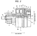
- FIG. 2 is a semi cross-section of the starter 1 shown in FIG. 1 .
- FIG. 2 shows a structure of a shock absorbing unit 9 and its peripheral parts in the starter 1 shown in FIG. 1 .
- the starter 1 has a motor 2, an electromagnetic relay 3, a back stop clutch 4 (or a one-way clutch), a reduction device 5, an output shaft 6, a pinion gear 8, a shock absorbing unit 9, and the like.
- An armature 2a of the motor 2 generates a rotational power in order to initiate an internal combustion engine (omitted from the drawings) to operate when receiving an electric power supplied from a battery (not shown).
- a main contact is placed in a motor circuit. The main contact will be explained later in detail.
- the electric power is supplied from the battery (not shown) to the armature 2a through the main contact which is open and closed by the electromagnetic relay 3.
- the back stop clutch 4 stops the armature 2a to rotate in opposite direction.
- the reduction device 5 reduces the rotation speed of the armature 2a.
- An output torque of the motor 2 is transmitted to the internal combustion engine through the output shaft 6 and the pinion gear 8.
- the pinion gear 8 is engaged with the outer periphery of the output shaft 6 through a bearing 7.
- the shock absorbing unit 9 is placed on the outer periphery of the output shaft 6.
- the starter 1 according to the first embodiment is applied to an automatic engine stop/re-start system.
- the automatic engine stop/re-start system automatically controls the operation of the internal combustion engine (not shown) to start and stop.
- the motor 2 is a well-known rectifier electric motor in which a rectifier 10 is placed at one end (at the right side in FIG. 1 ) of an armature shaft 2b through which the output torque of the armature 2a is transmitted, and the electric power is supplied to the armature 2a through a brush 11 which is placed at the outer periphery of the rectifier 10.
- the other end of the armature 2b is relatively and rotatably inserted through a bearing 14 (see FIG. 2 ) in an inside of a cavity part formed in the end part of the output shaft 6.
- the end frame 13 is assembled to an opening of an end side of a yoke 15 so that it is engaged with this opening.
- the end frame 13 is fastened and fixed to a starter housing 16 by some through bolts (not shown).
- the yoke 15 forms a magnet circuit of the motor 2.
- the electromagnetic relay 3 has a solenoid and a contact cover 19 made of resin fixed to the solenoid.
- the solenoid has a built-in electromagnet coil 17 and a built-in plunger 18. A main contact is placed in the contact cover 19.
- the solenoid generates electromagnetic force when receiving an electric power, and attracts the plunger 18.
- the function of the solenoid is a well-known matter.
- the plunger 18 controls the main contact to open/close.
- the main contact has B fixed contact 22 and M fixed contact 24, and a movable contact 25.
- the B fixed contact 22 is electrically connected to a high voltage potential side (battery side) of the motor circuit through a B terminal bolt 21.
- the M fixed contact 24 is electrically connected to a low voltage potential side (motor side) of the motor circuit through a M terminal bolt 23.
- the movable contact 25, together with the plunger 18, moves in order to open/close the B fixed contact 22 and the M fixed contact 24.
- the B fixed contact 22 is electrically connected to the M fixed contact 24, and the main contact falls in a closed state.
- the B fixed contact 22 and the M fixed contact 24 are respectively fixed to the contact cover 19.
- a terminal of a battery cable (not shown) is electrically connected to a front end part of the B terminal bolt 21.
- the B terminal bolt 21 projects from the contact cover 19 toward the axial direction of the output shaft 6.
- a terminal of a motor lead 26 is electrically connected to a front end part of the M terminal bolt 23.
- the M terminal bolt 23 also projects from the contact cover 19 toward the axial direction of the output shaft 6.
- a motor-side end part of the motor lead 26 is inserted into the inside of the motor 2 through a grommet 27 made of rubber which is placed between the yoke 15 and the end frame 13.
- the motor-side end part of the motor lead 26 is electrically connected to the brush 11 of a positive (+) electrode side.
- the back stop clutch 4 (or a one-way clutch) is comprised of an inner member 28, an outer member 29, a roller 30, and the like.
- the inner member 28 is placed at a part of the armature shaft 2b.
- a plurality of cam boxes (not shown) is formed by the outer member 29 between the outer peripheral surface of the inner member 28 and the outer member 29.
- the roller 30 is placed in the cam boxes.
- the outer member 29 has an outer wall part 29a which projects toward the outside in the diameter direction (or the radius direction) of the outer member 29.
- the outer peripheral part of the outer wall part 29a is held between the yoke 15 and the spacer member 31 and fixed toward the axial direction of the outer member 29.
- the outer peripheral part of the outer wall part 29a is also limited in rotation by the starter housing 16.
- the cam boxes are formed in a wedge shape which becomes narrow toward the anti-rotation direction of the armature shaft 2b.
- the roller 30 is pushed by a spring (not shown) toward the direction (which is the opposite direction of the armature direction 2b) to which the space of each cam box is gradually decreased.
- the roller 30 serves as a means of transmitting or halting the torque between the inner member 28 and the outer member 29.
- the back stop clutch 4 (or an one-way clutch) is capable of halting the reverse rotation of the armature 2a when the internal combustion engine initiates its reverse rotation, and the reversing rotation is transmitted to the starter 1. That is, the reversing rotation from the internal combustion engine is propagated to the pinion gear 8, the shock absorbing unit 9, the output shaft 6, the reduction device 5, and finally to the armature shaft 2b.
- the roller 30 moves toward the direction, to which each cam box becomes narrow, and the roller 30 is then locked between the inner member 28 and the outer member 29. The reversing rotation of the armature 2a is thereby halted.
- the roller 30 moves toward the direction to which the space of each cam box is wide so that the roller 30 races, namely, falls in idling, and the armature shaft 2b starts to rotate.
- the reduction device 5 is a planet gear type reduction device capable of reducing the rotation speed.
- the reduction device 5 and the armature shaft 2b are a coaxial system.
- the reduction device 5 is comprised of a sun gear 32, an internal (or annulus) gear 33, and a planet gear 34.
- the sun gear 32 is placed on the armature axis 2b at the opposite side of the rectifying device.
- the internal (or annulus) gear 33 (see FIG. 2 ) is limited in rotation through a torque limiter (will be explained below).
- the planet gear 34 (see FIG. 2 ) is engaged with the sun gear 32 and the internal (or annulus) gear 33. The orbital motion of the planet gear 34 is transmitted to the output shaft 6.
- the torque limiter is comprised of a fixed disk 36, a rotary disk 37, a disk spring 38 (belleville), and the like.
- the fixed disk 36 is limited in rotation by a central case 35.
- the rotary disk 37 is limited in rotation by a friction generated between the rotary disk 37 and the fixed disk 36, and between the rotary disk 37 and the central case 35.
- the disk spring 38 pushes the rotary disk 37 inserted between the fixed disk 36 and the rotary disk 37 toward the axial direction.
- the central case 35 is placed in the inside of the starter housing 16 so that it is perpendicular to the output shaft 6.
- the central case 35 is fixed in position so that it contacts to a step-shaped part formed in the inner periphery of the starter housing 16. This central case 35 is also limited in rotation to the starter housing 16.
- the output shaft 6 and the armature shaft 2b are placed to have a same axial line. Further, the end part of the output shaft 6 at the opposite side of the motor 2 is rotatably supported by the front end of the starter housing 16 through the bearing 39. Still further, the end part of the output shaft 6 at the motor 2 side is engaged with the reduction device 5 and also rotatably supported by the central case 35 through the bearing 40 (see FIG. 2 ).
- the pinion gear 8 is always engaged with the ring gear 41 at the engine side and further engaged with the output shaft 6 through the shock absorbing unit 9.
- the structure and actions of the shock absorbing unit 9 will be explained later in detail.
- the pinion gear 8 is contacted to a pinion stopper 43 in order to prevent the pinion gear 8 from being separated from the output shaft 6.
- This pinion stopper 43 is assembled to the end part of the output shaft 6 through a sealing ring 42.
- the sealing ring 42 is fitted to a circumferential groove 44 formed on the outer circumference of the output shaft 6.
- FIG. 3 is a plan view of a ring spacer 47 in the shock absorbing unit 9 in the starter 1 according to the first embodiment. Elastic members are accommodated in the ring spacer 47.
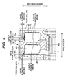
- FIG. 4 is an enlarged cross section of gaps formed in the shock absorbing unit 9 in the starter 1 according to the first embodiment.
- the shock absorbing unit 9 has a ring drive 45 as a primary case, a ring drive 46 as a secondary case, and the ring spacer 47 as an intermediate case, elastic members 48, and the like.
- the elastic members 48 are assembled between the ring drive 45 and the ring spacer 47, and between the ring spacer 47 and the ring drive 46.
- a boss part 45a of a cylindrical shape is formed at a central part in the diameter direction of the ring drive 45.
- This boss part 45a is engaged in a spline connection with the outer periphery of a cylindrical part 8a.
- This cylindrical part 8a and the pinion gear 8 are made with one body.
- the boss part 45a is so engaged with the pinion gear 8 through the cylindrical part 8a so as not to relatively rotate with the pinion gear 8.
- a boss part 46a of a cylindrical shape is formed at a central part of the ring drive 46 as the secondary case.
- the boss part 46a is engaged in a spline connection with the outer periphery of the output shaft 6.
- the boss part 46a is so engaged with the output shaft 6 so as not to relatively rotate with the output shaft 6.
- the ring spacer 47 is placed between the ring drive 45 and the ring drive 46, and is rotatably engaged with the outer periphery of the boss part 46a formed in the ring drive 46.
- a plurality of damper spaces S (see FIG. 3 ) is formed between the ring drive 45 and the ring spacer 47, and between the ring spacer 47 and the ring drive 46.
- the ring drive 45 faces the ring spacer 47 in the axial direction of the output shaft 6.
- the ring spacer 47 faces the ring drive 46 in the axial direction of the output shaft 6.
- Elastic members 48 are placed in the damper spaces S.
- FIG. 3 shows the three damper spaces S. The present invention is not limited by the number of the damper spaces S.
- the ring drives 45 and 46 are made of metal such as iron so as to obtain a desired strength for transmitting the output torque of the starter 1. On the other hand, it is possible to make the ring spacer 47 using resin in order to decrease the total weight of the starter 1.
- the elastic members 48 is comprised of a main block part 48a, a bridging part 48b, and a sub block part 48c.
- the sub block part 48c is connected to the main block part 48a through the bridging part 48b.
- the main block part 48a, the bridging part 48b, and the sub block part 48c are made with one body, and for example, made of oil-proof synthetic rubber.
- Each elastic member 48 is accommodated in each of the three damper spaces S formed between the ring drive 45 and the ring spacer 47. Each elastic member 48 is also accommodated in each of the three damper spaces S formed between the ring spacer 47 and the ring drive 46.
- Grease is applied as lubricant in the inside of the shock absorbing unit 9 so as to smoothly bend the elastic members 48 when a shock is applied to the starter 1.
- the grease is applied between the surfaces of the elastic members 48, the ring drive 45, the ring spacer 47, and the ring drive 46.
- the ring drive 45 and the ring spacer 47 which are adjacent to each other relatively and rotatably face together through the elastic members 48.
- the ring spacer 47 and the ring drive 46 are adjacent to each other, and relatively and rotatably face together through the elastic members 48.
- axial gaps A and A-1 and diameter gaps B and B-1 are formed between the outer periphery of the ring drive 45 and the outer periphery of the ring spacer 47 and between the outer periphery of the ring spacer 47 and the outer periphery of the ring drive 46.
- the axial gaps A and A-1 are formed in the axial direction of the shock absorbing unit 9 (, namely in the axial direction of the output shaft 6).
- the diameter gaps B and B-1 are formed in the diameter direction of the shock absorbing unit 9.
- the ring drive 45 has a facing-wall area
- the ring spacer 47 has a facing-wall area.
- Those facing-wall areas are formed in the diameter direction of the outside of the damper space S between the ring drive 45 and the ring spacer 47.
- Those facing-wall areas face together at a predetermined interval which will be referred to as the "gap A in the axial direction" (see the left side in FIG. 4 ).
- the gap A is formed between those facing-wall areas of the ring drive 45 and the ring spacer 47.
- An outer peripheral wall 47a of a ring shape is formed at the outer diameter part of the ring spacer 47.
- This outer peripheral wall 47a of a ring shape is extended toward the opposite side (the left side in FIG. 4 ) of the motor 2 along the axial direction from the facing-wall area. It is so formed that the inner diameter of the outer peripheral wall 47a is larger than the outer diameter of the ring drive 45 in order to form the gap B in the diameter direction (see FIG. 4 ) between the inner periphery of the outer peripheral wall 47a and the outer periphery of the ring drive 45.
- the gap A in the axial direction and the gap B in the diameter direction are connected (or communicated) together in a character "L" shape.
- the gap A and the gap B make a passage through which the grease and air flow out to the outside of the shock absorbing unit 9.
- the ring drive 46 has a facing-wall area
- the ring spacer 47 has another facing-wall area.
- Those facing-wall areas are formed in the diameter direction of the outside of the damper space S between the ring drive 46 and the ring spacer 47.
- Those facing walls face together at a predetermined interval which will be referred to as the "gap A-1 in the axial direction" (see the right side in FIG. 4 ).
- the gap A-1 is formed between those facing-wall areas of the ring drive 46 and the ring spacer 47.
- An outer peripheral wall 47a of a ring shape is formed at the outer diameter part of the ring spacer 47.
- This outer peripheral wall 47a of a ring shape is extended toward the motor side (toward the right side in FIG. 4 ) along the axial direction from the facing-wall area. It is so formed that the inner diameter of the outer peripheral wall 47a is larger than the outer diameter of the ring drive 46 in order to form the gap B-1 in the diameter direction (see FIG. 4 ) between the inner periphery of the outer peripheral wall 47a and the outer periphery of the ring drive 46.
- the gap A-1 in the axial direction and the gap B-1 in the diameter direction are connected (or communicated) in a character "L" shape. That is, the gap A-1 and the gap B-1 also make a passage through which the grease and air flow out to the outside of the shock absorbing unit 9.
- Each of the gaps A and A-1 in the axial direction has a length necessary to assemble the sealing ring 42 into the circumferential groove 44 formed in the surface of the output shaft 6 and further to assemble the pinion stopper 43 through the sealing ring 42 to the output shaft 6.
- each of the gaps B and B-1 is formed to be smaller in length than each of the gap A and A-1.
- those gaps A, A-1, B, and B-1 are formed as small as possible to be free from contacting to each other when the ring drives 45 and 46 and the ring spacer 47 relatively rotate.
- the electromagnetic relay 3 When the electromagnetic relay 3 electrically closes the main contact of the motor circuit in the motor 2 of the starter 1, the electric power is supplied from the battery to the armature 2a in the motor 2. The armature 2a thereby starts to rotate. The rotation speed of the armature 2a is reduced by the reduction device 5. The reduced rotation is transmitted to the output shaft 6. The reduced rotation is transmitted to the pinion gear 8 from the output shaft 6 through the shock absorbing unit 9. The rotation of the pinion gear 8 is transmitted to the ring gear 41 so as to crank the internal combustion engine (not shown).
- a one-way clutch incorporated in a ring gear 41 is connected to a pinion gear.
- the reversing rotation of the internal combustion engine is transmitted to the pinion gear through the ring gear.
- the starter 1 because the starter 1 according to the first embodiment has the back stop clutch 4 (or the one-way clutch) capable of preventing the armature 2a from reversely rotating, it is possible to prevent the armature 2a from being in a reverse rotation even if the reverse rotation of the internal combustion engine is transmitted to the starter 1.
- the back stop clutch 4 or the one-way clutch
- the shock absorbing unit 9 is capable of absorbing a shock which is generated when the ring gear 41 attacks the pinion gear 8 during the cranking or when the internal combustion engine (not shown) reversely rotates, for example.
- the ring drive 45 and the ring drive 46 placed in the shock absorbing unit 9 relatively rotate through the ring spacer 47, and the elastic members 48 are bent (namely, are compresses and deformed) toward the circumferential direction of the starter 1.
- the torque limiter is capable of interrupting the transmission of an excessive shock by sliding the rotary disk 37 toward the direction against a friction when such an excessive shock, which could not be absorbed by the shock absorbing unit 9, is applied to the output shaft 6, where the excessive shock exceeds a predetermined torque which is set in advance (or a sliding torque of the rotary disk 37) in the torque limiter.
- the shock absorbing unit 9 in the starter 1 avoids the starter 1 from directly receiving an excessive shock transmitted through the torque transmission path, it is possible to avoid the starter 1 from a damage which would be caused by receiving an excessive shock transmitted from the internal combustion engine side.
- the shock absorbing unit 9 assembled in the starter 1 according to the first embodiment of the present invention starts to rotate when the output shaft 6 rotates by receiving the rotational power of the motor 2. Accordingly, the grease applied in the inside of the shock absorbing unit 9 tends to move toward the outer periphery of the shock absorbing unit 9 by centrifugal force when the shock absorbing unit 9 rotates in synchronization with the output shaft 6.
- the gaps A and B are formed in a character "L" shape between the outer periphery of the ring drive 45 and the outer periphery of the ring spacer 47.
- the gaps A-1 and B-1 are formed in a character "L” shape between the outer periphery of the ring spacer 47 and the outer periphery of the ring drive 46, respectively, it is possible to prevent the grease from flowing out to the outside of the shock absorbing unit 9.
- the shock absorbing unit 9 has the structure in which each gap B (or B-1) measured in the diameter direction is smaller in length than each gap A (or A-1) measured in the axial direction, the shock absorbing unit 9 has a high ability of preventing the grease from being scattered to the outside.
- the structure of the shock absorbing unit 9 can keep the grease applied to the inside of the shock absorbing unit 9 for a long period of time.
- the shock absorbing unit 9 incorporated in the starter 1 according to the first embodiment provides a stable shock-absorbing capability for a long period of time because the elastic members 48 are smoothly bent according to the relative rotation of the ring drive 45 and the ring drive 46 when receiving a shock transmitted from the internal combustion engine side.
- the shock absorbing unit 9 assembled in the starter 1 according to the first embodiment has the gaps A and A-1 in the axial direction of the shock absorbing unit 9 between the outer periphery of the ring drive 45 and the outer periphery of the ring spacer 47 and between the outer periphery of the ring spacer 47 and the outer periphery of the ring drive 46, respectively. It is thereby possible to shift or bend the shock absorbing unit 9 by the gaps A and A-1 by pushing the ring drive 45 toward the ring drive 46 side when the sealing ring 42 is fitted into the peripheral groove 45 formed in the output shaft 6.
- shock absorbing unit 9 incorporated in the starter 1 according to a second embodiment of the present invention with reference to FIG. 5 .
- FIG. 5 is a plan view of a ring spacer in the shock absorbing unit incorporated in the starter according to the second embodiment of the present invention.
- FIG. 6 is a cross section of the ring spacer along C-C line shown in FIG. 5 .
- a concave part 49 is formed in the inner wall surface of each damper space S which is formed in the ring spacer 47-1.
- This inner wall surface will be also referred to as the "sliding surface”.
- the concave parts 49 are formed in the ring spacer 47-1 in the second embodiment, it is possible to form one or more the concave parts 49 in the sliding surface of at least one of the ring drive 45, the ring drive 46, and the ring spacer 47-1.
- the second embodiment will describe the example in which the concave parts 49 are formed only in the ring spacer 47-1
- each concave part 49 is formed in a circular arc shape at the central part of the sliding surface in the radial direction.
- each concave part 49 in the radial direction is not more than 1/2 times of the length of the elastic member 48 in the radial direction.
- the structure of the starter according to the second embodiment makes it possible to hold the grease in the concave part 49 formed in the sliding surface (or in the inner wall surface) of each damper space S. Further, because the sliding surface has a step shaped part, as the outer periphery of the concave part 49, formed at the outside in the diameter direction (or the radius direction) of the shock absorbing unit 9, the structure of the concave part 49 prevents the grease from moving toward the outer periphery side when the centrifugal force is applied to the grease after the shock absorbing unit 9 starts to rotate. That is, it is possible to keep the grease in each concave part 49 for a long period of time.
- the starter 1 it is possible for the starter 1 to provide the stably shock-absorbing capability for a long period of time because the presence of the concave parts 49 in the shock absorbing unit 9 prevents the grease from being scattered to the outside of the shock absorbing unit 9 and the elastic members 48 are smoothly bent according to the relative rotation between the ring drive 45 and the ring drive 46 even if receiving the shock propagated from the internal combustion engine side.
- the concave part 49 is formed at the central part in the diameter direction of the sliding surface of each dumber space S and the length of the concave part 49 in the diameter direction is within a range of not more than 1/2 times of the elastic member 48 in the diameter direction, there is no possibility of hanging a part of the elastic member 48 on the corresponding concave part 49, and thereby no possibility of preventing the motion of the elastic member 48. That is, the structure of the shock absorbing unit 9 in the starter according to the second embodiment can adequately keep the grease in each concave part 49 while maintaining the sliding capability of each elastic member 48.
- each concave part 49 has a circular-arc shape along the peripheral direction of the sliding surface, it is possible to effectively supply the grease held in each concave part 49 to the area between the sliding surface of the ring drives 45 and 46, the ring spacer 47, and the elastic member 48.
- the structure of the starter 1 can maintain the sliding capability of the elastic members 48 and has an improved capability of keeping the grease in the cases 45, 46, and 47 even if the shock absorbing unit 9 receives the shock propagated from the internal combustion engine side, it is possible to provide the starter 1 equipped with the shock absorbing unit 9 with the stable shock-absorbing capability for a long period of time.
- the present invention is not limited by the structure of the starter according to the second embodiment shown in FIG. 5 and FIG. 6 .
- the ring spacer 47 is placed between the ring drive 45 and the ring drive 46, and the six elastic members 48 are placed in double stages in series through the ring spacer 47. It is also possible to add one or more additional ring spacers and to place the elastic members 48 in not less than three stages in the ring spacers in series.
- the shock absorbing unit 9 in the starter 1 it is also possible to place the elastic members 48 between the ring drive 45 and the ring drive 46 without using the ring spacer 47.
- the gap A in the axial direction and the gap B in the diameter direction are formed between the outer periphery of the ring drive 45 and the outer periphery of the ring drive 46.
- This structure further has the concave parts 49 formed in the surface of the ring drive 45 and the ring drive 46 in this structure.
- the first embodiment of the present invention shows the structure in which the gap A and the gap B (also the gap A-1 and the gap B-1) are formed in a character "L" shape.
- the present invention is not limited by this, it is possible to alternately form the gaps A (A-1) in the axial direction and the gaps B (B-1) in the diameter direction (also the gap A-1 and the gap B-1) in a labyrinth structure.
- the starter 1 has the structure in which the pinion gear 8 is always engaged with the ring gear 41.
- the present invention is not limited by this structure.
- the concept of the present invention is applied to various types of the starters, for example, to a starter in which the pinion gear is pushed toward the opposite direction of the motor in order to engage the pinion gear with the ring gear 41 when an internal combustion engine starts to operate, and the pinion gear 8 is separated from the ring gear 41 after completion of the start of the internal combustion engine.
Landscapes
- Engineering & Computer Science (AREA)
- Chemical & Material Sciences (AREA)
- Combustion & Propulsion (AREA)
- Mechanical Engineering (AREA)
- General Engineering & Computer Science (AREA)
- Connection Of Motors, Electrical Generators, Mechanical Devices, And The Like (AREA)
Abstract
Description
- The present invention relates to a starter equipped with a shock absorbing unit capable of reducing damage caused by shock applied from the internal combustion side through a pinion gear.
- There are conventional techniques relating many types of starters. For example, Japanese patent laid open publication No.
JP 2006-207573 -
FIG. 7 shows a conventional starter having anoutput shaft 100, apinion gear 120, and ashock absorbing unit 130. Theoutput shaft 100 is driven by a motor (not shown) to rotate. Thepinion gear 120 is engaged with the outer periphery of theoutput shaft 100 through abearing 110. Theshock absorbing unit 130 is placed between theoutput shaft 100 and thepinion gear 120. - The
shock absorbing unit 130 assembled in the conventional starter has aprimary case 140, asecondary case 160, and anintermediate case 160,rubber dampers 170 and the like. Theprimary case 140 is engaged in spline connection with the outer periphery of the cylindrical part which is assembled with thepinion gear 120. Thesecondary case 150 is engaged in spline connection with the outer periphery of theoutput shaft 100. Theintermediate case 160 is relatively and rotatably placed between theprimary case 140 and thesecondary case 150. Therubber dampers 170 are assembled between theprimary case 140, theintermediate case 160, and thesecondary case 150. - For example, when receiving a shock transmitted or propagated from the internal combustion engine (not shown) side during cranking, the
primary case 140 and thesecondary case 150 rotate relatively to theintermediate case 160, and therubber dampers 170 are compressed and deformed toward a circumferential direction in order to absorb the shock and to reduce the damage of the shock. - A description will now be given of the assembling procedure of the conventional starter equipped with the shock absorbing unit described above.
- First, the
shock absorbing unit 130 and thepinion gear 120 are fitted and engaged with theoutput shaft 100. Thepinion stopper 180 is then fitted and engaged to theoutput shaft 100 in order to fix thepinion gear 120 to theoutput shaft 100. - The
pinion stopper 180 is temporarily shifted along theoutput shaft 100 toward the motor side (namely, toward the right direction inFIG. 7 ), a character "C" ring 200 (hereinafter, referred to as the "sealing ring 200") is engaged with acircumferential groove 190 formed on the surface of theoutput shaft 100. After this, thepinion stopper 180 is then returned in the axial direction toward the opposite from the motor (not shown) along theoutput shaft 100 in order to stop thepinion stopper 180 by thesealing ring 200. - The assembling work needs to push and bend the
primary case 140 and thesecondary case 150 in the shock absorbing unit 130 (specifically, to push theprimary case 140 toward thesecondary case 150 side) in order to shift thepinion stopper 180 toward the motor side along theoutput shaft 100. In order to achieve this work, a gap of a predetermined width is formed between theprimary case 140 and theintermediate case 160, and a gap of a predetermined width is also formed between theintermediate case 160 and thesecondary case 150. That is, the presence of those gaps in theshock absorbing unit 130 enables thepinion stopper 180 to be shifted toward the motor side along theoutput shaft 100. - By the way, grease is applied on sliding surfaces of the
rubber dampers 170, theprimary case 140, theintermediate case 160, and thesecondary case 150 in theshock absorbing unit 130. The presence of the grease enhances the sliding capability of therubber dampers 170, and absorbs a shock by smoothly pushing and bending therubber dampers 170 when the shock is propagated from an internal combustion engine side and applied to the starter. - However, in the
shock absorbing unit 130 of the conventional starter, the presence of those gaps formed between theprimary case 140 and theintermediate case 160 and between theintermediate case 160 and thesecondary case 150 has a possibility that the grease flows out to the outside of theshock absorbing unit 130 through those gaps by a centrifugal force generated when theshock absorbing unit 130 rotates together with therotary shaft 100. Flowing out of most of the grease from theshock absorbing unit 130 through the gaps makes it difficult to smoothly bend therubber dampers 170. This decreases the function of theshock absorbing unit 130. In order to avoid such a drawback, because the structure of the conventional starter requires an excess amount of the grease in advance, the manufacturing cost of the starter equipped with theshock absorbing unit 130 having the above structure is increased. - It is an object of the present invention to provide a starter equipped with a shock absorbing unit of an improved structure which is capable of providing a stable shock-absorbing capability while suppressing grease which is held in the shock absorbing unit from flowing out by centrifugal force generated when the shock absorbing unit rotates together with a rotary shaft of the starter.
- To achieve the above purpose, the present invention provides a starter (1) equipped with a shock absorbing unit (9). The starter (1) is comprised of a motor (2), an output shaft (6), a pinion gear (8), and the shock absorbing unit (9).
- The motor (2) generates a rotation power and supplies the rotation power to an internal combustion engine to start to rotate through the output shaft (6) and the pinion gear (8) and a ring gear (41). The output shaft (6) rotates when receiving the rotation power transmitted from the motor (2). The pinion gear (8) is rotatably placed at an outer periphery of the output shaft (6) through a bearing (7). The pinion gear (8) transmits the rotation power generated by the motor (2) to the ring gear (41) of the internal combustion engine. In the starter (1), the shock absorbing unit (9) is placed at the outer periphery of the output shaft (6). The shock absorbing unit (9) has elastic members (48) therein. The shock absorbing unit (9) is capable of reducing a shock. That is, the elastic members (48) are compressed and deformed when receiving the shock from the internal combustion engine side through the pinion gear (8). In particular, the shock absorbing unit (9) has a primary case (45) engaged with the pinion gear (8), a secondary case (46) engaged with the output shaft (6), and those elastic members (48) placed between the primary case (45) and the secondary case (46). The primary case (45) and the secondary case (46) are rotatably placed through the elastic members (48). Gaps "A" and "A-1" in the axial direction of shock absorbing unit (9) (also of the output shaft (6)) and gaps "B" and "B-1" in a diameter direction of the shock absorbing unit (9) (also of the output shaft (6)) are formed between an outer periphery of the primary case (45) and an outer periphery of the secondary case (46).
- In general, the shock absorbing unit (9) rotates together with the output shaft (6) of the motor (2) when the motor (2) starts to rotate. During the rotation of the shock absorbing unit (9) in synchronization with the output shaft (6) of the motor (2), the grease applied on the inside (more detailed, on the sliding surface on which the elastic members (48) slides and are bent when receiving a shock) of the primary case (45) and the secondary case (46) tends to move and fly out toward the outer periphery of the shock absorbing unit (9) by a centrifugal force generated by the rotation.
- On the other hand, in the shock absorbing unit (9) assembled to the starter (1) according to the present invention, the gap "A" in the axial direction and the gap "B" in the diameter direction which are connected together are formed in the outer periphery of the primary case (45) and the outer periphery of the secondary case (46).
- This structure of those gaps "A", "A-1", "B", and "B-1" can prevent the grease from moving and flying out toward the outside of the primary case (45) and the secondary case (46) in the shock absorbing unit (9). That is, the structure of the shock absorbing unit (9) can prevent the grease from flying out toward the outside of the primary case (45) and the secondary case (46). Because the structure of the shock absorbing unit (9) can keep the grease applied in the inside of the primary case (45) and the secondary case (46) for a long period of time, it is possible to smoothly compress and bend the elastic members (48) by the relative rotation between the primary case (45) and the secondary case (46) when the shock is applied to the shock absorbing unit (9) from the internal combustion engine (9) side. The starter (1) equipped with the shock absorbing unit (9) according to the present invention maintains the stable shock-absorbing capability for a long period of time.
- Because the shock absorbing unit (9) in the starter (1) according to the present invention has the gaps "A" and "A-1" in the axial direction between the outer periphery of the primary case (45) and the outer periphery of the secondary case (46), it is possible to easily move the primary case (45) toward the secondary case (46) using the gap when the sealing ring is assembled into the peripheral groove which is formed on the outer periphery of the output shaft (6) in the assembling work, like the assembling work of the conventional starter disclosed in the Japanese patent laid open publication No.
JP 2006-207573 - According to the present invention, the starter (1) equipped with the shock absorbing unit (9) uses the conventional manufacturing procedure, without any change, from the step of fitting the shock absorbing unit and the pinion gear to the output shaft, fitting a sealing ring to the peripheral groove formed on the output shaft, and to the step of stopping the pinion stopper by the presence of the sealing ring.
- In accordance with another aspect of the present invention, there is provided the starter (1) equipped with the shock absorbing unit (9). The starter (1) is comprised of the motor (2), the output shaft (6), the pinion gear (8), and the shock absorbing unit (9). The motor (2) generates a rotation power to be supplied to the internal combustion engine to start to rotate. The output shaft (6) rotates when receiving the rotation power transmitted from the motor (2). The pinion gear (8) is rotatably placed at the outer periphery of the output shaft (6) through the bearing (7). The pinion gear (8) transmits the rotation power generated by the motor (2) to the ring gear for the internal combustion engine.
- The shock absorbing unit (9) is placed on the outer periphery of the output shaft (6). The shock absorbing unit (9) has the elastic members (48). The shock absorbing unit (9) is capable of reducing a shock by compressing and deforming the elastic members (48) when receiving the shock applied from the internal combustion engine side through the pinion gear (8). In particular, the shock absorbing unit (9) has the primary case (45) connected to the pinion gear (8), the secondary case (46) connected to the output shaft (6), and one or more intermediate cases (47) placed between the primary case (45) and the secondary case (46).
- Through the intermediate case (47), the elastic members (48) are assembled in multiple stages in series between the primary case (45) and the secondary case (46). The primary case (45) and the intermediate case (47) are rotatably and relatively placed through the elastic members (48). Similarly, the intermediate case (47) and the secondary case (46) are rotatably and relatively placed through the elastic members (48). The gaps "A" and "A-1" formed in the axial direction of the shock absorbing unit (9) and the gaps B and "B-1" formed in the diameter direction of the shock absorbing unit (9) are formed between the outer periphery of the primary case (45) and the outer periphery of the intermediate case (47) and also between the outer periphery of the intermediate case (47) and the outer periphery of the secondary case (46).
- In general, because the shock absorbing unit (9) rotates in synchronization with the output shaft (6) when receiving the rotary power transmitted from the motor (2), the grease applied in the inside of the primary case (45), the intermediate case (47), and the secondary case (46), tends to move and fly out toward the outer periphery of the shock absorbing unit (9) in the diameter direction, specifically, the grease is applied on the sliding surfaces, on which the elastic members (48) bend and slide, of the primary case (45), the intermediate case (47), and the secondary case (46).
- On the other hand, according to the present invention, the gap "A" in the axial direction and the gap "B" in the diameter direction are formed between the outer periphery of the primary case (45) and the intermediate case (47), and the gap "A-1" in the axial direction and the gap "B-1" in the diameter direction are formed between the outer periphery of the intermediate case (47) and the outer periphery of the secondary case (46). The above structure of the shock absorbing unit (9) can prevent the grease from moving to and flying out directly toward the outside of those cases (45, 46, and 47). That is, the structure of the shock absorbing unit (9) can prevent the grease from flowing out of each of the primary case (45), the secondary case (46), and the intermediate case (47). In addition to this, the presence of the gaps "A", "A-1", "B", and "B-1" in the shock absorbing unit (9) keeps the grease in those cases (45, 46, and 47) for a long period of time. Accordingly, even if a shock is propagated from the internal combustion engine side to the starter (1), because the elastic members are smoothly compressed and bent according to the relative rotation between the primary case (45) and the secondary case (46) through the intermediate case (47), the starter (1) equipped with the shock absorbing unit (9) has the stable shock-absorbing capability.
- Further, because the shock absorbing unit (9) in the starter (1) according to the present invention has the gap "A" formed in the axial direction between the outer periphery of the primary case (45) and the gap "A-1" in the axial direction between the outer periphery of the intermediate case (47) and the outer periphery of the secondary case (46), it is possible for the shock absorbing unit (9) to move within the gap, namely, the primary case (45) is pushed toward the secondary case (46) side when the sealing ring is assembled into the peripheral groove formed on the outer periphery of the output shaft (6), like the conventional starter disclosed in the Japanese patent laid open publication No.
JP 2006-207573 - In the starter as another aspect of the present invention, the gaps in the axial direction and the gaps in the diameter direction are alternately formed in a labyrinth structure.
- In the starter (1) according to the present invention, the gaps are formed in a labyrinth structure between the outer periphery of the primary case (45) and the outer periphery of the secondary case (46). This structure enhances the capability of preventing the grease from flying out which is caused by centrifugal force.
- Similarly, in the starter (1) according to the present invention, the gaps are formed in a labyrinth structure between the outer periphery of the primary case (45) and the outer periphery of the intermediate case (47) and between the outer periphery of the intermediate case (47) and the outer periphery of the secondary case (46). This structure also enhances the capability of preventing the grease from flying out which is caused by centrifugal force.
- In the starter as another aspect of the present invention, it is so formed that the gap "B" and "B-1" in the diameter direction is narrower than the gap A and A-1. In the assembling work for the starter (1) according to the present invention, it is needed to shift the shock absorbing unit (9) toward the axial direction of the output shaft (6) side of the starter (1) (specifically, it is needed to push the primary case (45) to the secondary case (46) side) in order to fit the pinion stopper (43) to the output shaft (6). In order to complete this assembling work, it is required to have the gaps formed in the axial direction formed between the outer periphery of the primary case (45) and the outer periphery of the secondary case (46), or formed between the outer periphery of the primary case (45) and the outer periphery of the intermediate case (47) and between the outer periphery of the intermediate case (47) and the outer periphery of the secondary case (46). That is, assembling the pinion stopper (43) needs the gaps in the axial direction of the shock absorbing unit (9).
- On the other hand, because the assembling work for the starter (1) does not use the gaps "B" and "B-1" formed in the diameter direction, it is possible to form the gaps "B" and "B-1" smaller in length (namely, size) than the gaps "A" and "A-1" unless the primary case (45) and the secondary case (46) interact with each other. As a result, the above structure of the starter (1) with the gaps "A", "A-1", and "B", "B-1" ensures the capability of suppressing the grease from flowing out toward the outside of the cases (45, 46, and 47). In other words, the structure of the starter (1) according to the present invention increases the capability of keeping the grease in the shock absorbing unit.
- In accordance with another aspect of the present invention, there is provided a starter (1) comprised of a motor (2), an output shaft (6), a pinion gear (8), and a shock absorbing unit (9). The motor (2) generates a rotation power when receiving the electric power, for example, supplied from a battery. The output shaft (6) starts to rotate when receiving the rotation power transmitted from the motor (2). The pinion gear (8) is rotatably placed at an outer periphery of the output shaft (6) through the bearing (7) and transmits the rotation power generated by the motor (2) to the ring gear (41) for the internal combustion engine. In particular, the shock absorbing unit (9) is placed on the outer periphery of the output shaft (6). The shock absorbing unit (9) has one or more elastic members (48). When receiving a shock propagated or supplied from the internal combustion engine side, the elastic members (48) are compressed and deformed in order to absorb the shock. The shock absorbing unit (9) has the primary case (45) engaged with the pinion gear (8), the secondary case (46) engaged with the output shaft (6), and the elastic members (48) placed between the primary case (45) and the secondary case (46). In the starter (1) according to the present invention, the primary case (45) and the secondary case (46) are relatively and rotatably placed through the elastic members (48). In particular, one or more concave parts (49) are formed in a sliding surface of at least one of the primary case (45) and the secondary case (46) on which the elastic members (48) slide and are bent.
- The structure of the starter (1) according to the present invention enables the grease to be held in the concave parts (49) formed in the sliding surface of the primary case (45) and the secondary case (46). Further, the wall surfaces of the concave parts (49) suppress the grease held therein from moving and flying out toward the outside of the outer periphery of the primary case (45) and the secondary case (46) by centrifugal force when the shock absorbing unit (9) rotates. Thus, the concave parts (49) in the shock absorbing unit (9) assembled in the starter (1) according to the present invention effectively holds the grease. As a result, when a shock is applied from the internal combustion engine side to the starter (1), the structure of the starter (1) enables the elastic members (48) to be smoothly bent according to the relative rotation of the primary case (45) and the secondary case (46), and thereby provides a stable shock-absorbing capability.
- In accordance with another aspect of the present invention, there is provided the starter (1) comprised of the motor (2), the output shaft (6), the pinion gear (8), and the shock absorbing unit (9). The motor (2) generates a rotation power when receiving the electric power, for example, supplied from a battery. The output shaft (6) initiates to rotate when receiving the rotation power transmitted from the motor (2). The pinion gear (8) is rotatably placed on the outer periphery of the output shaft (6) through the bearing (7) and transmits the rotation power generated by the motor (2) to the ring gear for the internal combustion engine. The shock absorbing unit (9) is placed on the outer periphery of the output shaft (6). The shock absorbing unit (9) has one or more the elastic members (48) therein. When receiving a shock propagated from the internal combustion engine side, the elastic members (48) slide and are bent in order to absorb the shock. The shock absorbing unit (9) is capable of reducing the shock propagated from the internal combustion engine side through the pinion gear (8) and the ring gear (41). The shock absorbing unit (9) has the primary case (45) connected to the pinion gear (8), the secondary case (46) connected to the output shaft (6), at least one intermediate case (47) which is placed between the primary case (45) and the secondary case (46). The elastic members (48) are placed in multiple stages in series between the primary case (45) and the secondary case (46) through the intermediate case (47).
- In the starter (1) according to the present invention, the primary case (45) and the intermediate case (47) are relatively and rotatably placed through the elastic members (48). The intermediate case (47) and the secondary case (46) are relatively and rotatably placed through the elastic members (48). In particular, one or more concave parts (49) are formed in the sliding surface of at least one of the primary case (45) and the intermediate case (47) where the elastic member (48) slides and is bent. Thus, the concave parts (49) are formed in the sliding surface of at least one of the intermediate case (47) and the secondary case (46) where the elastic member (48) slides and are bent.
- According to the above structure of the starter (1), it is possible to hold the grease in the concave parts (49) formed in the sliding surface of those cases (45, 46, and 47). Further, the wall surfaces of the concave parts (49) suppress the grease held therein from moving and flying out toward the outside of the outer periphery of the primary, secondary, and intermediate cases (45, 46, and 47) by centrifugal force when the shock absorbing unit (9) rotates. Thus, the structure of the starter (1) equipped with the shock absorbing unit (9) effectively holds the grease in the concave parts (49). As a result, even if a shock is propagated from the internal combustion engine side to the starter (1), the above structure of the starter (1) enables the elastic members (48) to be smoothly bent according to the relative rotation of the primary case (45) and the secondary case (46), and thereby provides a stable shock-absorbing capability.
- In the starter as another aspect of the present invention, the gaps "A" and "A-1" in the axial direction of the shock absorbing unit (9) and the gaps "B" and "B-1" in the diameter direction of the shock absorbing unit (9) are formed between the outer periphery of the primary case (45) and the outer periphery of the secondary case (46). The gap in the axial direction is connected to the gap in the diameter direction.
- This structure of the starter (1) provides an improved effect to suppress flowing out of the grease which is held in the cases (45, 46, and 47) and the concave parts (49) in addition to the prescribed effects of the starter (1).
- In the starter as another aspect of the present invention, the gap "A" in the axial direction and the gap "B" in the diameter direction of the shock absorbing unit (9) are formed between an outer periphery of the primary case (45) and the outer periphery of the intermediate case (47). The gap "A-1" in the axial direction and the gap "B-1" in the diameter direction of the shock absorbing unit (9) are formed between the outer periphery of the intermediate case (47) and the outer periphery of the secondary case (46). The gap "A" in the axial direction is connected to the gap "B" in the diameter direction, and the gap "A-1" in the axial direction is connected to the gap "B-1" in the diameter direction. This structure of the starter (1) also provides the enhancement of the effect to suppress flowing out of the grease which is held in the cases and the concave parts (49) in addition to the prescribed effects of the starter (1).
- In the starter as another aspect of the present invention, each concave part is formed with a circular-arc shape in a central part of the sliding surface in the diameter direction along the circumferential direction of those cases (45, 46, and 47). When the concave part (49) is formed in the diameter direction at an end part, not the central part of the sliding surface of the case, there is a possibility of hanging a part of the elastic member (48) by the concave part (49) when the elastic members (48) are bent by receiving the shock propagated from the internal combustion engine side to the starter (1). This makes it difficult for the elastic members (48) to be smoothly bent. On the other hand, according to the present invention, because the concave parts (49) are formed in the diameter direction at the central part of each sliding surface of the case, it is possible for the elastic members (48) to smoothly slide without losing the sliding capability. Still further, because the concave part (49) is formed in a circular-arc shape along the periphery of the sliding surface, this structure of the concave part effectively supplies the grease between the sliding surface of each case and the elastic members (48).
- In the starter as another aspect of the present invention, a length of each concave part in the diameter direction is not more than 1/2 times of a length of each elastic member in the diameter direction. If the size of the concave part in the radial direction is larger than that of each elastic member, there is a possibility of hanging a part of the elastic member (48) by the concave part (49) when the elastic members (48) are bent by receiving the shock applied from the internal combustion engine side to the starter (1). Forming the concave part (49) of not more than 1/2 of the size of the elastic member (48) in the diameter direction enables the elastic members to smoothly slide on the sliding surface without losing the sliding capability of the elastic member (48).
- In the starter as another aspect of the present invention, the pinion gear (8) is always engaged with the ring gear of the internal combustion engine. When the pinion gear (8) of the starter (1) is always engaged with the ring gear (41) of the internal combustion engine, the shock to be propagated to the starter (1) has following types (a) to (c):
- (a) The shock which is generated when the internal combustion engines initiates to rotate, that is, the shock is generated when the pinion gear knocks the ring gear by fluctuating the rotation speed of the engine shaft of the internal combustion engine during cranking;
- (b) The shock which is caused by a reverse rotation of the crank shaft generated when the internal combustion engine stops to operate; and
- (c) The shock which is generated when the engine of a vehicle stops on an uphill road, and the vehicle backs toward the opposite direction on the uphill road.
- The shock absorbing unit (9) assembled in the starter (1) according to the present invention has an important feature to absorb the shock propagated from the internal combustion engine side.
- According to another aspect of the present invention, the starter (1) is used in an automatic engine stopping/restarting system capable of controlling stopping and restarting the internal combustion engine.
- For example, the automatic engine stopping/restarting system (which is usually called to as the "idle reduction" or the "automobile emissions control" aimed at reducing the amount of energy wasted by an idling vehicle. For example, when a vehicle's engine is not being used to move the vehicle at an intersection or during a traffic jam, it can be shut off entirely-thereby conserving fuel and reducing automobile emissions-while other functions like accessories and lighting in the vehicle are powered by an electrical source other than a vehicle alternator. The automatic engine stopping/restarting system as the automobile emissions control then restarts the internal combustion engine by the driver operation.
- In the vehicle equipped with the automatic engine stopping/restarting system, the number of starting operations of the starter is larger than that of another vehicle without any automatic engine stopping/restarting system.
- That is, the vehicle equipped with the automatic engine stopping/restarting system has a large number of operations to start the internal combustion engine, namely, to start the starter (1).
- When the internal combustion engine starts to rotate (namely, during the cranking), the pinion gear strikes the ring gear by the fluctuation of the engine speed, and this generates noises and shock.
- According to the present invention, because the shock absorbing unit assembled in the starter is capable of reducing those noises and shock reduces those noises and shock, it is possible to apply the starter according to the present invention to vehicles equipped with the automatic engine stopping/restarting system in order to reduce those noises and shock.
- A preferred, non-limiting embodiment of the present invention will be described by way of example with reference to the accompanying drawings, in which:
-
FIG. 1 is a cross section of a starter according to a first embodiment of the present invention; -
FIG. 2 is a semi cross-section of the starter shown inFIG. 1 , in particular, shows a structure of a shock absorbing unit, and its peripheral parts in the starter shown inFIG. 1 ; -
FIG. 3 is a plan view of a ring spacer in the shock absorbing unit incorporated in the starter according to the first embodiment into which elastic members are accommodated; -
FIG. 4 is an enlarged cross section of gaps formed in the shock absorbing unit in the starter according to the first embodiment; -
FIG. 5 is a plan view of a ring spacer in the shock absorbing unit incorporated in the starter according to a second embodiment of the present invention; -
FIG. 6 is a cross section of the ring spacer along C-C line shown inFIG. 5 ; and -
FIG. 7 is a semi cross-section of a shock absorbing unit in a conventional starter. - Hereinafter, various embodiments of the present invention will be described with reference to the accompanying drawings. In the following description of the various embodiments, like reference characters or numerals designate like or equivalent component parts throughout the several diagrams.
- A description will now be given of a
starter 1 according to a first embodiment of the present invention with reference toFIG. 1 to FIG. 4 . -
FIG.1 is a cross section of thestarter 1 according to the embodiments of the present invention.FIG. 2 is a semi cross-section of thestarter 1 shown inFIG. 1 . In particular,FIG. 2 shows a structure of ashock absorbing unit 9 and its peripheral parts in thestarter 1 shown inFIG. 1 . - As shown in
FIG. 1 , thestarter 1 according to the first embodiment has amotor 2, anelectromagnetic relay 3, a back stop clutch 4 (or a one-way clutch), areduction device 5, anoutput shaft 6, apinion gear 8, ashock absorbing unit 9, and the like. An armature 2a of themotor 2 generates a rotational power in order to initiate an internal combustion engine (omitted from the drawings) to operate when receiving an electric power supplied from a battery (not shown). A main contact is placed in a motor circuit. The main contact will be explained later in detail. The electric power is supplied from the battery (not shown) to the armature 2a through the main contact which is open and closed by theelectromagnetic relay 3. Theback stop clutch 4 stops the armature 2a to rotate in opposite direction. Thereduction device 5 reduces the rotation speed of the armature 2a. An output torque of themotor 2 is transmitted to the internal combustion engine through theoutput shaft 6 and thepinion gear 8. Thepinion gear 8 is engaged with the outer periphery of theoutput shaft 6 through abearing 7. Theshock absorbing unit 9 is placed on the outer periphery of theoutput shaft 6. - The
starter 1 according to the first embodiment is applied to an automatic engine stop/re-start system. The automatic engine stop/re-start system automatically controls the operation of the internal combustion engine (not shown) to start and stop. - The
motor 2 is a well-known rectifier electric motor in which arectifier 10 is placed at one end (at the right side inFIG. 1 ) of an armature shaft 2b through which the output torque of the armature 2a is transmitted, and the electric power is supplied to the armature 2a through abrush 11 which is placed at the outer periphery of therectifier 10. - One end of the armature shaft 2b, which projects from the
rectifier 10, is rotatably supported by anend frame 13 through thebearing 12. The other end of the armature 2b is relatively and rotatably inserted through a bearing 14 (seeFIG. 2 ) in an inside of a cavity part formed in the end part of theoutput shaft 6. - The
end frame 13 is assembled to an opening of an end side of a yoke 15 so that it is engaged with this opening. Theend frame 13 is fastened and fixed to astarter housing 16 by some through bolts (not shown). The yoke 15 forms a magnet circuit of themotor 2. - The
electromagnetic relay 3 has a solenoid and acontact cover 19 made of resin fixed to the solenoid. The solenoid has a built-inelectromagnet coil 17 and a built-inplunger 18. A main contact is placed in thecontact cover 19. The solenoid generates electromagnetic force when receiving an electric power, and attracts theplunger 18. The function of the solenoid is a well-known matter. Theplunger 18 controls the main contact to open/close. - Because the electromagnetic force disappears when the supply of the electric power to the
solenoid 18 stops, theplunger 18 is returned to the original position by the force accumulated in areturn spring 20. The main contact is thereby open. - The main contact has B fixed
contact 22 and M fixedcontact 24, and amovable contact 25. The B fixedcontact 22 is electrically connected to a high voltage potential side (battery side) of the motor circuit through aB terminal bolt 21. The M fixedcontact 24 is electrically connected to a low voltage potential side (motor side) of the motor circuit through aM terminal bolt 23. Themovable contact 25, together with theplunger 18, moves in order to open/close the B fixedcontact 22 and the M fixedcontact 24. When themovable contact 25 is electrically contacted to the B fixedcontact 22 and the M fixedcontact 24, the B fixedcontact 22 is electrically connected to the M fixedcontact 24, and the main contact falls in a closed state. - On the other hand, when the
movable contact 25 is separated from the B fixedcontact 22 and the M fixedcontact 24, the B fixedcontact 22 is also separated from the M fixedcontact 24, and the main contact falls in an open state. - The B fixed
contact 22 and the M fixedcontact 24 are respectively fixed to thecontact cover 19. A terminal of a battery cable (not shown) is electrically connected to a front end part of theB terminal bolt 21. TheB terminal bolt 21 projects from thecontact cover 19 toward the axial direction of theoutput shaft 6. Like theB terminal bolt 21, a terminal of amotor lead 26 is electrically connected to a front end part of theM terminal bolt 23. TheM terminal bolt 23 also projects from thecontact cover 19 toward the axial direction of theoutput shaft 6. - A motor-side end part of the
motor lead 26 is inserted into the inside of themotor 2 through agrommet 27 made of rubber which is placed between the yoke 15 and theend frame 13. The motor-side end part of themotor lead 26 is electrically connected to thebrush 11 of a positive (+) electrode side. - The back stop clutch 4 (or a one-way clutch) is comprised of an inner member 28, an outer member 29, a roller 30, and the like. The inner member 28 is placed at a part of the armature shaft 2b. A plurality of cam boxes (not shown) is formed by the outer member 29 between the outer peripheral surface of the inner member 28 and the outer member 29. The roller 30 is placed in the cam boxes.
- The outer member 29 has an
outer wall part 29a which projects toward the outside in the diameter direction (or the radius direction) of the outer member 29. The outer peripheral part of theouter wall part 29a is held between the yoke 15 and thespacer member 31 and fixed toward the axial direction of the outer member 29. The outer peripheral part of theouter wall part 29a is also limited in rotation by thestarter housing 16. The cam boxes are formed in a wedge shape which becomes narrow toward the anti-rotation direction of the armature shaft 2b. - The roller 30 is pushed by a spring (not shown) toward the direction (which is the opposite direction of the armature direction 2b) to which the space of each cam box is gradually decreased. The roller 30 serves as a means of transmitting or halting the torque between the inner member 28 and the outer member 29.
- The back stop clutch 4 (or an one-way clutch) is capable of halting the reverse rotation of the armature 2a when the internal combustion engine initiates its reverse rotation, and the reversing rotation is transmitted to the
starter 1. That is, the reversing rotation from the internal combustion engine is propagated to thepinion gear 8, theshock absorbing unit 9, theoutput shaft 6, thereduction device 5, and finally to the armature shaft 2b. When the reversing rotation reaches the armature shaft 2b, the roller 30 moves toward the direction, to which each cam box becomes narrow, and the roller 30 is then locked between the inner member 28 and the outer member 29. The reversing rotation of the armature 2a is thereby halted. - On the other hand, when the
starter 1 drives the internal combustion engine, the roller 30 moves toward the direction to which the space of each cam box is wide so that the roller 30 races, namely, falls in idling, and the armature shaft 2b starts to rotate. - The
reduction device 5 is a planet gear type reduction device capable of reducing the rotation speed. Thereduction device 5 and the armature shaft 2b are a coaxial system. Thereduction device 5 is comprised of asun gear 32, an internal (or annulus)gear 33, and aplanet gear 34. Thesun gear 32 is placed on the armature axis 2b at the opposite side of the rectifying device. The internal (or annulus) gear 33 (seeFIG. 2 ) is limited in rotation through a torque limiter (will be explained below). The planet gear 34 (seeFIG. 2 ) is engaged with thesun gear 32 and the internal (or annulus)gear 33. The orbital motion of theplanet gear 34 is transmitted to theoutput shaft 6. - As shown in
FIG. 2 , the torque limiter is comprised of a fixeddisk 36, arotary disk 37, a disk spring 38 (belleville), and the like. The fixeddisk 36 is limited in rotation by acentral case 35. Therotary disk 37 is limited in rotation by a friction generated between therotary disk 37 and the fixeddisk 36, and between therotary disk 37 and thecentral case 35. Thedisk spring 38 pushes therotary disk 37 inserted between the fixeddisk 36 and therotary disk 37 toward the axial direction. - When an excess torque over a slip torque of the
rotary disk 37 is applied to the internal gear 33 (or annulus gear), therotary disk 37 slips (or, rotates) against the friction. Because this limits the rotation of theinternal gear 33, the excess torque is not propagated. - The
central case 35 is placed in the inside of thestarter housing 16 so that it is perpendicular to theoutput shaft 6. Thecentral case 35 is fixed in position so that it contacts to a step-shaped part formed in the inner periphery of thestarter housing 16. Thiscentral case 35 is also limited in rotation to thestarter housing 16. - The
output shaft 6 and the armature shaft 2b are placed to have a same axial line. Further, the end part of theoutput shaft 6 at the opposite side of themotor 2 is rotatably supported by the front end of thestarter housing 16 through thebearing 39. Still further, the end part of theoutput shaft 6 at themotor 2 side is engaged with thereduction device 5 and also rotatably supported by thecentral case 35 through the bearing 40 (seeFIG. 2 ). - The
pinion gear 8 is always engaged with the ring gear 41 at the engine side and further engaged with theoutput shaft 6 through theshock absorbing unit 9. The structure and actions of theshock absorbing unit 9 will be explained later in detail. - The
pinion gear 8 is contacted to apinion stopper 43 in order to prevent thepinion gear 8 from being separated from theoutput shaft 6. Thispinion stopper 43 is assembled to the end part of theoutput shaft 6 through a sealingring 42. The sealingring 42 is fitted to acircumferential groove 44 formed on the outer circumference of theoutput shaft 6. - Next, a description will now be given of the
shock absorbing unit 9 assembled in thestarter 1 according to the first embodiment of the present invention with reference toFIG. 2 ,FIG. 3 , andFIG. 4 . -
FIG. 3 is a plan view of aring spacer 47 in theshock absorbing unit 9 in thestarter 1 according to the first embodiment. Elastic members are accommodated in thering spacer 47.FIG. 4 is an enlarged cross section of gaps formed in theshock absorbing unit 9 in thestarter 1 according to the first embodiment. - As shown in
FIG. 2 , theshock absorbing unit 9 has aring drive 45 as a primary case, aring drive 46 as a secondary case, and thering spacer 47 as an intermediate case,elastic members 48, and the like. Theelastic members 48 are assembled between thering drive 45 and thering spacer 47, and between thering spacer 47 and thering drive 46. - As shown in
FIG. 2 , aboss part 45a of a cylindrical shape is formed at a central part in the diameter direction of thering drive 45. Thisboss part 45a is engaged in a spline connection with the outer periphery of acylindrical part 8a. Thiscylindrical part 8a and thepinion gear 8 are made with one body. Theboss part 45a is so engaged with thepinion gear 8 through thecylindrical part 8a so as not to relatively rotate with thepinion gear 8. - Like the
ring drive 45, aboss part 46a of a cylindrical shape is formed at a central part of thering drive 46 as the secondary case. Theboss part 46a is engaged in a spline connection with the outer periphery of theoutput shaft 6. Theboss part 46a is so engaged with theoutput shaft 6 so as not to relatively rotate with theoutput shaft 6. - The
ring spacer 47 is placed between thering drive 45 and thering drive 46, and is rotatably engaged with the outer periphery of theboss part 46a formed in thering drive 46. - A plurality of damper spaces S (see
FIG. 3 ) is formed between thering drive 45 and thering spacer 47, and between thering spacer 47 and thering drive 46. The ring drive 45 faces thering spacer 47 in the axial direction of theoutput shaft 6. Thering spacer 47 faces thering drive 46 in the axial direction of theoutput shaft 6.Elastic members 48 are placed in the damper spaces S.FIG. 3 shows the three damper spaces S. The present invention is not limited by the number of the damper spaces S. - The ring drives 45 and 46 are made of metal such as iron so as to obtain a desired strength for transmitting the output torque of the
starter 1. On the other hand, it is possible to make thering spacer 47 using resin in order to decrease the total weight of thestarter 1. - As shown in
FIG. 3 , theelastic members 48 is comprised of amain block part 48a, a bridgingpart 48b, and asub block part 48c. Thesub block part 48c is connected to themain block part 48a through the bridgingpart 48b. Themain block part 48a, the bridgingpart 48b, and thesub block part 48c are made with one body, and for example, made of oil-proof synthetic rubber. - Each
elastic member 48 is accommodated in each of the three damper spaces S formed between thering drive 45 and thering spacer 47. Eachelastic member 48 is also accommodated in each of the three damper spaces S formed between thering spacer 47 and thering drive 46. - Grease is applied as lubricant in the inside of the
shock absorbing unit 9 so as to smoothly bend theelastic members 48 when a shock is applied to thestarter 1. In more detail, the grease is applied between the surfaces of theelastic members 48, thering drive 45, thering spacer 47, and thering drive 46. Thering drive 45 and thering spacer 47 which are adjacent to each other relatively and rotatably face together through theelastic members 48. Similarly, thering spacer 47 and thering drive 46 are adjacent to each other, and relatively and rotatably face together through theelastic members 48. - As shown in
FIG. 4 , axial gaps A and A-1 and diameter gaps B and B-1 are formed between the outer periphery of thering drive 45 and the outer periphery of thering spacer 47 and between the outer periphery of thering spacer 47 and the outer periphery of thering drive 46. The axial gaps A and A-1 are formed in the axial direction of the shock absorbing unit 9 (, namely in the axial direction of the output shaft 6). The diameter gaps B and B-1 are formed in the diameter direction of theshock absorbing unit 9. - A description will now be given of the axial gaps A, A-1 and the diameter gaps B and B-1 in detail with reference to
FIG. 4 . - The
ring drive 45 has a facing-wall area, and thering spacer 47 has a facing-wall area. Those facing-wall areas are formed in the diameter direction of the outside of the damper space S between thering drive 45 and thering spacer 47. Those facing-wall areas face together at a predetermined interval which will be referred to as the "gap A in the axial direction" (see the left side inFIG. 4 ). In other words, as shown inFIG. 4 , the gap A is formed between those facing-wall areas of thering drive 45 and thering spacer 47. - An outer
peripheral wall 47a of a ring shape is formed at the outer diameter part of thering spacer 47. This outerperipheral wall 47a of a ring shape is extended toward the opposite side (the left side inFIG. 4 ) of themotor 2 along the axial direction from the facing-wall area. It is so formed that the inner diameter of the outerperipheral wall 47a is larger than the outer diameter of thering drive 45 in order to form the gap B in the diameter direction (seeFIG. 4 ) between the inner periphery of the outerperipheral wall 47a and the outer periphery of thering drive 45. As clearly shown inFIG. 4 , the gap A in the axial direction and the gap B in the diameter direction are connected (or communicated) together in a character "L" shape. The gap A and the gap B make a passage through which the grease and air flow out to the outside of theshock absorbing unit 9. - Similarly, the
ring drive 46 has a facing-wall area, and thering spacer 47 has another facing-wall area. Those facing-wall areas are formed in the diameter direction of the outside of the damper space S between thering drive 46 and thering spacer 47. Those facing walls face together at a predetermined interval which will be referred to as the "gap A-1 in the axial direction" (see the right side inFIG. 4 ). In other words, as shown inFIG. 4 , the gap A-1 is formed between those facing-wall areas of thering drive 46 and thering spacer 47. - An outer
peripheral wall 47a of a ring shape is formed at the outer diameter part of thering spacer 47. This outerperipheral wall 47a of a ring shape is extended toward the motor side (toward the right side inFIG. 4 ) along the axial direction from the facing-wall area. It is so formed that the inner diameter of the outerperipheral wall 47a is larger than the outer diameter of thering drive 46 in order to form the gap B-1 in the diameter direction (seeFIG. 4 ) between the inner periphery of the outerperipheral wall 47a and the outer periphery of thering drive 46. As clearly shown inFIG. 4 , the gap A-1 in the axial direction and the gap B-1 in the diameter direction are connected (or communicated) in a character "L" shape. That is, the gap A-1 and the gap B-1 also make a passage through which the grease and air flow out to the outside of theshock absorbing unit 9. - Each of the gaps A and A-1 in the axial direction has a length necessary to assemble the sealing
ring 42 into thecircumferential groove 44 formed in the surface of theoutput shaft 6 and further to assemble thepinion stopper 43 through the sealingring 42 to theoutput shaft 6. - Furthermore, each of the gaps B and B-1 is formed to be smaller in length than each of the gap A and A-1. Preferably, those gaps A, A-1, B, and B-1 are formed as small as possible to be free from contacting to each other when the ring drives 45 and 46 and the
ring spacer 47 relatively rotate. - Next, a description will now be given of the operation of the
starter 1 according to the first embodiment of the present invention. - When the
electromagnetic relay 3 electrically closes the main contact of the motor circuit in themotor 2 of thestarter 1, the electric power is supplied from the battery to the armature 2a in themotor 2. The armature 2a thereby starts to rotate. The rotation speed of the armature 2a is reduced by thereduction device 5. The reduced rotation is transmitted to theoutput shaft 6. The reduced rotation is transmitted to thepinion gear 8 from theoutput shaft 6 through theshock absorbing unit 9. The rotation of thepinion gear 8 is transmitted to the ring gear 41 so as to crank the internal combustion engine (not shown). - When the rotation speed of the internal combustion engine exceeds the rotation speed of the
starter 1 after the internal combustion engine starts to rotate, the one-way clutch (not shown) assembled into the ring gear 41 starts to race. Because this interrupts the transmission of the torque between the crank shaft of the internal combustion engine and the ring gear 41, the rotation of the internal combustion engine is not transmitted to thepinion gear 8. This prevents the armature 2a of themotor 2 in thestarter 1 from being overrun. - By the way, when an internal combustion engine causes a reverse rotation by a fluctuation of a crank shaft caused when the internal combustion engine stops, or by running a vehicle in reverse on an uphill slope when the internal combustion engine stops, a one-way clutch incorporated in a ring gear 41 is connected to a pinion gear. In a starter having the structure in which the pinion gear is always engaged with the ring gear, the reversing rotation of the internal combustion engine is transmitted to the pinion gear through the ring gear.
- On the other hand, because the
starter 1 according to the first embodiment has the back stop clutch 4 (or the one-way clutch) capable of preventing the armature 2a from reversely rotating, it is possible to prevent the armature 2a from being in a reverse rotation even if the reverse rotation of the internal combustion engine is transmitted to thestarter 1. - The
shock absorbing unit 9 is capable of absorbing a shock which is generated when the ring gear 41 attacks thepinion gear 8 during the cranking or when the internal combustion engine (not shown) reversely rotates, for example. - When receiving such a shock, the
ring drive 45 and thering drive 46 placed in theshock absorbing unit 9 relatively rotate through thering spacer 47, and theelastic members 48 are bent (namely, are compresses and deformed) toward the circumferential direction of thestarter 1. - The torque limiter is capable of interrupting the transmission of an excessive shock by sliding the
rotary disk 37 toward the direction against a friction when such an excessive shock, which could not be absorbed by theshock absorbing unit 9, is applied to theoutput shaft 6, where the excessive shock exceeds a predetermined torque which is set in advance (or a sliding torque of the rotary disk 37) in the torque limiter. - Because the presence of the
shock absorbing unit 9 in thestarter 1 avoids thestarter 1 from directly receiving an excessive shock transmitted through the torque transmission path, it is possible to avoid thestarter 1 from a damage which would be caused by receiving an excessive shock transmitted from the internal combustion engine side. - The
shock absorbing unit 9 assembled in thestarter 1 according to the first embodiment of the present invention starts to rotate when theoutput shaft 6 rotates by receiving the rotational power of themotor 2. Accordingly, the grease applied in the inside of theshock absorbing unit 9 tends to move toward the outer periphery of theshock absorbing unit 9 by centrifugal force when theshock absorbing unit 9 rotates in synchronization with theoutput shaft 6. - On the other hand, the gaps A and B are formed in a character "L" shape between the outer periphery of the
ring drive 45 and the outer periphery of thering spacer 47. The gaps A-1 and B-1 are formed in a character "L" shape between the outer periphery of thering spacer 47 and the outer periphery of thering drive 46, respectively, it is possible to prevent the grease from flowing out to the outside of theshock absorbing unit 9. - Specifically, even if the grease flows out from the damper spaces S to the gaps A and A-1 in the axial direction by a centrifugal force, because the outer
peripheral wall 47a covers the outside in the diameter direction of the gaps A and A-1 measured in the axial direction, it is possible to prevent the grease from being scattered to the outside of theshock absorbing unit 9 through the gaps A and A-1. Still further, because theshock absorbing unit 9 has the structure in which each gap B (or B-1) measured in the diameter direction is smaller in length than each gap A (or A-1) measured in the axial direction, theshock absorbing unit 9 has a high ability of preventing the grease from being scattered to the outside. - As a result, the structure of the
shock absorbing unit 9 can keep the grease applied to the inside of theshock absorbing unit 9 for a long period of time. Theshock absorbing unit 9 incorporated in thestarter 1 according to the first embodiment provides a stable shock-absorbing capability for a long period of time because theelastic members 48 are smoothly bent according to the relative rotation of thering drive 45 and thering drive 46 when receiving a shock transmitted from the internal combustion engine side. - Still further, the
shock absorbing unit 9 assembled in thestarter 1 according to the first embodiment has the gaps A and A-1 in the axial direction of theshock absorbing unit 9 between the outer periphery of thering drive 45 and the outer periphery of thering spacer 47 and between the outer periphery of thering spacer 47 and the outer periphery of thering drive 46, respectively. It is thereby possible to shift or bend theshock absorbing unit 9 by the gaps A and A-1 by pushing thering drive 45 toward thering drive 46 side when the sealingring 42 is fitted into theperipheral groove 45 formed in theoutput shaft 6. - It is possible to perform the assembling step (from the step of fitting the
shock absorbing unit 9 and thepinion gear 8 into theoutput shaft 6, to the step of locking thepinion stopper 43 by the sealing ring 42) by the same manner disclosed in the conventional technique, for example, Japanese patent laid open publication No.JP 2006-207573 - A description will be given of the
shock absorbing unit 9 incorporated in thestarter 1 according to a second embodiment of the present invention with reference toFIG. 5 . -
FIG. 5 is a plan view of a ring spacer in the shock absorbing unit incorporated in the starter according to the second embodiment of the present invention.FIG. 6 is a cross section of the ring spacer along C-C line shown inFIG. 5 . - As shown in
FIG. 5 andFIG. 6 , aconcave part 49 is formed in the inner wall surface of each damper space S which is formed in the ring spacer 47-1. This inner wall surface will be also referred to as the "sliding surface". - Although the
concave parts 49 are formed in the ring spacer 47-1 in the second embodiment, it is possible to form one or more theconcave parts 49 in the sliding surface of at least one of thering drive 45, thering drive 46, and the ring spacer 47-1. The second embodiment will describe the example in which theconcave parts 49 are formed only in the ring spacer 47-1 - As shown in
FIG. 5 , eachconcave part 49 is formed in a circular arc shape at the central part of the sliding surface in the radial direction. - It is so formed that the length of each
concave part 49 in the radial direction is not more than 1/2 times of the length of theelastic member 48 in the radial direction. - The structure of the starter according to the second embodiment makes it possible to hold the grease in the
concave part 49 formed in the sliding surface (or in the inner wall surface) of each damper space S. Further, because the sliding surface has a step shaped part, as the outer periphery of theconcave part 49, formed at the outside in the diameter direction (or the radius direction) of theshock absorbing unit 9, the structure of theconcave part 49 prevents the grease from moving toward the outer periphery side when the centrifugal force is applied to the grease after theshock absorbing unit 9 starts to rotate. That is, it is possible to keep the grease in eachconcave part 49 for a long period of time. As a result, it is possible for thestarter 1 to provide the stably shock-absorbing capability for a long period of time because the presence of theconcave parts 49 in theshock absorbing unit 9 prevents the grease from being scattered to the outside of theshock absorbing unit 9 and theelastic members 48 are smoothly bent according to the relative rotation between thering drive 45 and thering drive 46 even if receiving the shock propagated from the internal combustion engine side. - Still further, because the
concave part 49 is formed at the central part in the diameter direction of the sliding surface of each dumber space S and the length of theconcave part 49 in the diameter direction is within a range of not more than 1/2 times of theelastic member 48 in the diameter direction, there is no possibility of hanging a part of theelastic member 48 on the correspondingconcave part 49, and thereby no possibility of preventing the motion of theelastic member 48. That is, the structure of theshock absorbing unit 9 in the starter according to the second embodiment can adequately keep the grease in eachconcave part 49 while maintaining the sliding capability of eachelastic member 48. - Still further, because each
concave part 49 has a circular-arc shape along the peripheral direction of the sliding surface, it is possible to effectively supply the grease held in eachconcave part 49 to the area between the sliding surface of the ring drives 45 and 46, thering spacer 47, and theelastic member 48. As a result, because the structure of thestarter 1 can maintain the sliding capability of theelastic members 48 and has an improved capability of keeping the grease in thecases shock absorbing unit 9 receives the shock propagated from the internal combustion engine side, it is possible to provide thestarter 1 equipped with theshock absorbing unit 9 with the stable shock-absorbing capability for a long period of time. - The present invention is not limited by the structure of the starter according to the second embodiment shown in
FIG. 5 andFIG. 6 . For example, it is possible to combine the structure of the starter according to the first embodiment with the structure of the starter according to the second embodiment. This combination completely suppresses the grease from flowing out or being scattered to the outside of theshock absorbing unit 9. - The concept of the present invention is not limited by the first and second embodiments aforementioned above.
- In the
shock absorbing unit 9 assembled in thestarter 1 according to the first embodiment, thering spacer 47 is placed between thering drive 45 and thering drive 46, and the sixelastic members 48 are placed in double stages in series through thering spacer 47. It is also possible to add one or more additional ring spacers and to place theelastic members 48 in not less than three stages in the ring spacers in series. - In the structure of the
shock absorbing unit 9 in thestarter 1 according to each of the first and second embodiment prescribed above, it is also possible to place theelastic members 48 between thering drive 45 and thering drive 46 without using thering spacer 47. In this structure, the gap A in the axial direction and the gap B in the diameter direction are formed between the outer periphery of thering drive 45 and the outer periphery of thering drive 46. This structure further has theconcave parts 49 formed in the surface of thering drive 45 and thering drive 46 in this structure. - The first embodiment of the present invention shows the structure in which the gap A and the gap B (also the gap A-1 and the gap B-1) are formed in a character "L" shape. The present invention is not limited by this, it is possible to alternately form the gaps A (A-1) in the axial direction and the gaps B (B-1) in the diameter direction (also the gap A-1 and the gap B-1) in a labyrinth structure.
- The
starter 1 according to the first embodiment has the structure in which thepinion gear 8 is always engaged with the ring gear 41. The present invention is not limited by this structure. For example, the concept of the present invention is applied to various types of the starters, for example, to a starter in which the pinion gear is pushed toward the opposite direction of the motor in order to engage the pinion gear with the ring gear 41 when an internal combustion engine starts to operate, and thepinion gear 8 is separated from the ring gear 41 after completion of the start of the internal combustion engine. - While specific embodiments of the present invention have been described in detail, it will be appreciated by those skilled in the art that various modifications and alternatives to those details could be developed in light of the overall teachings of the disclosure. Accordingly, the particular arrangements disclosed are meant to be illustrative only and not limited to the scope of the present invention which is to be given the full breadth of the following claims and all equivalent thereof.
Claims (12)
- A starter (1) comprising:a motor (2) generating a rotation power;an output shaft (6) rotating when receiving the rotation power transmitted from the motor (2);a pinion gear (8) which is rotatably placed on an outer periphery of the output shaft (6) through a bearing (7) and transmits the rotation power generated by the motor (2) to a ring gear for an internal combustion engine; anda shock absorbing unit (9), placed on the outer periphery of the output shaft (6), capable of reducing a shock applied from the internal combustion engine through the pinion gear (8) by compressing and deforming elastic members (48), andthe shock absorbing unit (9) comprising:a primary case (45) engaged with the pinion gear (8);a secondary case (46) engaged with the output shaft (6); andthe elastic members (48) placed between the primary case (45) and the secondary case (46), wherein the primary case (45) and the secondary case (46) are rotatably placed through the elastic members (48), wherein gaps (A, A-1) in an axial direction of the shock absorbing unit (9) and gaps (B, B-1) in a diameter direction of the shock absorbing unit (9) are formed between an outer periphery of the primary case (45) and an outer periphery of the secondary case (46).
- The starter (1) as claimed in claim 1, wherein the shock absorbing unit (9) further comprises at least one intermediate case (47) which is placed between the primary case (45) and the secondary case (46), and
the elastic members (48) are assembled in multiple stages in series between the primary case (45) and the secondary case (46) through the intermediate case (47), and
the primary case (45) and the intermediate case (47) are relatively and rotatably placed through the elastic members (48), and the intermediate case (47) and the secondary case (46) are relatively and rotatably placed through the elastic members (48), and
the gaps (A, A-1) in the axial direction are formed between the outer periphery of the primary case (45) and an outer periphery of the intermediate case (47), and the gaps (B, B-1) in the diameter direction are formed between the outer periphery of the intermediate case (47) and the outer periphery of the secondary case (46). - The starter (1) as claimed in claim 1 or 2, wherein the gaps (A, A-1) in the axial direction and the gaps (B, B-1) in the diameter direction are alternately formed in a labyrinth structure.
- The starter (1) as claimed in any one of claims 1 to 3, wherein it is so formed that the gaps (B and B-1) in the diameter direction are narrower than the gaps (A and A-1).
- A starter (1) comprising:a motor (2) generating a rotation power;an output shaft (6) rotating when receiving the rotation power transmitted from the motor (2);a pinion gear (8) which is rotatably placed on an outer periphery of the output shaft (6) through a bearing (7) and transmits the rotation power generated by the motor (2) to a ring gear for an internal combustion engine; anda shock absorbing unit (9), placed on the outer periphery of the output shaft (6), capable of reducing a shock applied from the internal combustion engine through the pinion gear (8) by compressing and deforming an elastic members (48), the shock absorbing unit (9) comprising:a primary case (45) engaged with the pinion gear (8);a secondary case (46) engaged with the output shaft (6); andthe elastic members (48) placed between the primary case (45) and the secondary case (46),wherein the primary case (45) and the secondary case (46) are rotatably placed through the elastic members (48), whereina concave part (49) is formed in a sliding surface of at least one of the primary case (45) and the secondary case (46) where the elastic members (48) slide and are bent.
- The starter (1) as claimed in claim 5, wherein the shock absorbing unit (9) further comprises at least one intermediate case (47) which is placed between the primary case (45) and the secondary case (46), and
the elastic members (48) are assembled in multiple stages in series between the primary case (45) and the secondary case (46) through the intermediate case (47), and
the primary case (45) and the intermediate case (47) are relatively and rotatably placed through the elastic members (48), and the intermediate case (47) and the secondary case (46) are relatively and rotatably placed through the elastic members (48), and
the concave part (49) is formed in a sliding surface of at least one of the primary case (45) and the intermediate case (47) where the elastic members (48) slide and are bent, and
the concave part (49) is further formed in sliding surface of at least one of the intermediate case (47) and the secondary case (46) where the elastic members (48) slide and are bent. - The starter (1) as claimed in claim 5, wherein a gap (A, A-1) in an axial direction and a gap (B, B-1) in a diameter direction are formed between an outer periphery of the primary case (45) and an outer periphery of the secondary case (46) so that the gap (A, A-1) is connected to the gap (B, B-1).
- The starter (1) as claimed in claim 6, wherein a gap (A) in the axial direction and a gap (B) in the diameter direction are formed between an outer periphery of the primary case (45) and an outer periphery of the intermediate case (47), and a gap (A-1) in the axial direction and a gap (B-1) in the diameter direction are formed between the outer periphery of the intermediate case (47) and an outer periphery of the secondary case (46), and the gap (A) in the axial direction is connected to the gap (B) in the diameter direction, and the gap (A-1) in the axial direction is connected to the gap (B-1) in the diameter direction.
- The starter (1) as claimed in any one of claims 5 to 8, wherein each concave part is formed with a circular arc shape in a central part in the diameter direction of the sliding surface along the circumferential direction of the primary, secondary, and intermediate cases (45, 46, 47).
- The starter (1) as claimed in any one of claims 5 to 9, wherein a length of each concave part in the diameter direction is not more than 1/2 times of a length of each elastic member in the diameter direction.
- The starter (1) as claimed in any one of claims 5 to 10, wherein the pinion gear (8) is always engaged with the ring gear of the internal combustion engine.
- The starter (1) as claimed in claim 11, wherein the starter (1) is used in an engine automatic stopping/restarting system capable of controlling stopping and restarting the internal combustion engine.
Applications Claiming Priority (1)
| Application Number | Priority Date | Filing Date | Title |
|---|---|---|---|
| JP2007285123A JP2009114860A (en) | 2007-11-01 | 2007-11-01 | Starter |
Publications (3)
| Publication Number | Publication Date |
|---|---|
| EP2055937A2 true EP2055937A2 (en) | 2009-05-06 |
| EP2055937A3 EP2055937A3 (en) | 2010-07-21 |
| EP2055937B1 EP2055937B1 (en) | 2013-12-11 |
Family
ID=40297756
Family Applications (1)
| Application Number | Title | Priority Date | Filing Date |
|---|---|---|---|
| EP08017843.7A Ceased EP2055937B1 (en) | 2007-11-01 | 2008-10-10 | Starter |
Country Status (2)
| Country | Link |
|---|---|
| EP (1) | EP2055937B1 (en) |
| JP (1) | JP2009114860A (en) |
Cited By (2)
| Publication number | Priority date | Publication date | Assignee | Title |
|---|---|---|---|---|
| WO2011039357A1 (en) * | 2009-10-01 | 2011-04-07 | Robert Bosch Gmbh | Noise-optimized starting apparatus |
| FR2957637A1 (en) * | 2010-03-22 | 2011-09-23 | Valeo Equip Electr Moteur | STARTER EQUIPPED WITH A TORQUE LIMITER ASSOCIATED WITH A DRIVE GEAR AND CORRESPONDING TORQUE LIMITER |
Citations (1)
| Publication number | Priority date | Publication date | Assignee | Title |
|---|---|---|---|---|
| JP2006207573A (en) | 2004-12-27 | 2006-08-10 | Denso Corp | Starter |
Family Cites Families (4)
| Publication number | Priority date | Publication date | Assignee | Title |
|---|---|---|---|---|
| US2343967A (en) * | 1943-06-19 | 1944-03-14 | Briggs & Stratton Corp | Engine starter |
| FR1245046A (en) * | 1958-10-23 | 1960-11-04 | Bendix Aviat Corp | Reversible starter for internal combustion engine or similar |
| JPS5820962A (en) * | 1981-07-28 | 1983-02-07 | Hitachi Ltd | Starter pinion clutch mechanism |
| DE102005061669B4 (en) * | 2004-12-27 | 2016-01-21 | Denso Corporation | Shock-absorbing engine starter |
-
2007
- 2007-11-01 JP JP2007285123A patent/JP2009114860A/en active Pending
-
2008
- 2008-10-10 EP EP08017843.7A patent/EP2055937B1/en not_active Ceased
Patent Citations (1)
| Publication number | Priority date | Publication date | Assignee | Title |
|---|---|---|---|---|
| JP2006207573A (en) | 2004-12-27 | 2006-08-10 | Denso Corp | Starter |
Cited By (5)
| Publication number | Priority date | Publication date | Assignee | Title |
|---|---|---|---|---|
| WO2011039357A1 (en) * | 2009-10-01 | 2011-04-07 | Robert Bosch Gmbh | Noise-optimized starting apparatus |
| CN102549256A (en) * | 2009-10-01 | 2012-07-04 | 罗伯特·博世有限公司 | Noise-optimized starting apparatus |
| CN102549256B (en) * | 2009-10-01 | 2015-11-25 | 罗伯特·博世有限公司 | The starting arrangement of noise optimization |
| FR2957637A1 (en) * | 2010-03-22 | 2011-09-23 | Valeo Equip Electr Moteur | STARTER EQUIPPED WITH A TORQUE LIMITER ASSOCIATED WITH A DRIVE GEAR AND CORRESPONDING TORQUE LIMITER |
| EP2381086A1 (en) | 2010-03-22 | 2011-10-26 | Valeo Equipements Electriques Moteur | Starter provided with a torque limiter connected to a pinion and corresponding torque limiter |
Also Published As
| Publication number | Publication date |
|---|---|
| EP2055937A3 (en) | 2010-07-21 |
| EP2055937B1 (en) | 2013-12-11 |
| JP2009114860A (en) | 2009-05-28 |
Similar Documents
| Publication | Publication Date | Title |
|---|---|---|
| JP4174820B2 (en) | Starter | |
| KR100660620B1 (en) | Starter having excessive-torque-absorbing device | |
| US20050120814A1 (en) | Integral one-way overrun clutch with epicycle gear system | |
| US20080257077A1 (en) | Electric Starter Motor with Idle Gear | |
| US9188099B2 (en) | Starter | |
| CN103946538B (en) | Starter | |
| JP2008196373A (en) | Starter | |
| JP2979973B2 (en) | Starter with reduction mechanism | |
| JP4487976B2 (en) | Starter | |
| US5740694A (en) | Starter with planetary reduction gear mechanism | |
| JP4487984B2 (en) | Starter | |
| EP2055937B1 (en) | Starter | |
| JP6302719B2 (en) | Starter | |
| JP6069110B2 (en) | Starter | |
| CN101203673A (en) | Starter | |
| WO2013145299A1 (en) | Starter | |
| US8567364B2 (en) | Starter equipped with planetary speed reducer and shock absorber | |
| JPH08144908A (en) | Starter | |
| JP2013083178A (en) | Starter | |
| JP4466625B2 (en) | Starter | |
| JP2013130077A (en) | Starter | |
| JP2010196629A (en) | Starter | |
| JP2008057450A (en) | Always mesh starter | |
| JP2014105640A (en) | Pinion with built-in damper, and starter using pinion with built-in damper | |
| JP5873758B2 (en) | Starter |
Legal Events
| Date | Code | Title | Description |
|---|---|---|---|
| PUAI | Public reference made under article 153(3) epc to a published international application that has entered the european phase |
Free format text: ORIGINAL CODE: 0009012 |
|
| AK | Designated contracting states |
Kind code of ref document: A2 Designated state(s): AT BE BG CH CY CZ DE DK EE ES FI FR GB GR HR HU IE IS IT LI LT LU LV MC MT NL NO PL PT RO SE SI SK TR |
|
| AX | Request for extension of the european patent |
Extension state: AL BA MK RS |
|
| PUAL | Search report despatched |
Free format text: ORIGINAL CODE: 0009013 |
|
| AK | Designated contracting states |
Kind code of ref document: A3 Designated state(s): AT BE BG CH CY CZ DE DK EE ES FI FR GB GR HR HU IE IS IT LI LT LU LV MC MT NL NO PL PT RO SE SI SK TR |
|
| AX | Request for extension of the european patent |
Extension state: AL BA MK RS |
|
| 17P | Request for examination filed |
Effective date: 20100810 |
|
| AKX | Designation fees paid |
Designated state(s): DE FR |
|
| 17Q | First examination report despatched |
Effective date: 20111019 |
|
| GRAP | Despatch of communication of intention to grant a patent |
Free format text: ORIGINAL CODE: EPIDOSNIGR1 |
|
| INTG | Intention to grant announced |
Effective date: 20130628 |
|
| RIN1 | Information on inventor provided before grant (corrected) |
Inventor name: OHMURA, TOMOHIRO |
|
| GRAS | Grant fee paid |
Free format text: ORIGINAL CODE: EPIDOSNIGR3 |
|
| GRAA | (expected) grant |
Free format text: ORIGINAL CODE: 0009210 |
|
| AK | Designated contracting states |
Kind code of ref document: B1 Designated state(s): DE FR |
|
| REG | Reference to a national code |
Ref country code: DE Ref legal event code: R096 Ref document number: 602008029178 Country of ref document: DE Effective date: 20140206 |
|
| REG | Reference to a national code |
Ref country code: DE Ref legal event code: R084 Ref document number: 602008029178 Country of ref document: DE Effective date: 20140526 |
|
| REG | Reference to a national code |
Ref country code: DE Ref legal event code: R097 Ref document number: 602008029178 Country of ref document: DE |
|
| PLBE | No opposition filed within time limit |
Free format text: ORIGINAL CODE: 0009261 |
|
| STAA | Information on the status of an ep patent application or granted ep patent |
Free format text: STATUS: NO OPPOSITION FILED WITHIN TIME LIMIT |
|
| 26N | No opposition filed |
Effective date: 20140912 |
|
| REG | Reference to a national code |
Ref country code: DE Ref legal event code: R097 Ref document number: 602008029178 Country of ref document: DE Effective date: 20140912 |
|
| REG | Reference to a national code |
Ref country code: FR Ref legal event code: PLFP Year of fee payment: 8 |
|
| REG | Reference to a national code |
Ref country code: FR Ref legal event code: PLFP Year of fee payment: 9 |
|
| REG | Reference to a national code |
Ref country code: FR Ref legal event code: PLFP Year of fee payment: 10 |
|
| REG | Reference to a national code |
Ref country code: FR Ref legal event code: PLFP Year of fee payment: 11 |
|
| PGFP | Annual fee paid to national office [announced via postgrant information from national office to epo] |
Ref country code: DE Payment date: 20181019 Year of fee payment: 11 |
|
| PGFP | Annual fee paid to national office [announced via postgrant information from national office to epo] |
Ref country code: FR Payment date: 20181022 Year of fee payment: 11 |
|
| REG | Reference to a national code |
Ref country code: DE Ref legal event code: R119 Ref document number: 602008029178 Country of ref document: DE |
|
| PG25 | Lapsed in a contracting state [announced via postgrant information from national office to epo] |
Ref country code: DE Free format text: LAPSE BECAUSE OF NON-PAYMENT OF DUE FEES Effective date: 20200501 |
|
| PG25 | Lapsed in a contracting state [announced via postgrant information from national office to epo] |
Ref country code: FR Free format text: LAPSE BECAUSE OF NON-PAYMENT OF DUE FEES Effective date: 20191031 |