EP2055897A1 - Flexible Shims - Google Patents
Flexible Shims Download PDFInfo
- Publication number
- EP2055897A1 EP2055897A1 EP08103676A EP08103676A EP2055897A1 EP 2055897 A1 EP2055897 A1 EP 2055897A1 EP 08103676 A EP08103676 A EP 08103676A EP 08103676 A EP08103676 A EP 08103676A EP 2055897 A1 EP2055897 A1 EP 2055897A1
- Authority
- EP
- European Patent Office
- Prior art keywords
- shim
- projection
- fitted
- rotor
- turbine
- Prior art date
- Legal status (The legal status is an assumption and is not a legal conclusion. Google has not performed a legal analysis and makes no representation as to the accuracy of the status listed.)
- Withdrawn
Links
Images


Classifications
-
- F—MECHANICAL ENGINEERING; LIGHTING; HEATING; WEAPONS; BLASTING
- F01—MACHINES OR ENGINES IN GENERAL; ENGINE PLANTS IN GENERAL; STEAM ENGINES
- F01D—NON-POSITIVE DISPLACEMENT MACHINES OR ENGINES, e.g. STEAM TURBINES
- F01D5/00—Blades; Blade-carrying members; Heating, heat-insulating, cooling or antivibration means on the blades or the members
- F01D5/30—Fixing blades to rotors; Blade roots ; Blade spacers
- F01D5/3023—Fixing blades to rotors; Blade roots ; Blade spacers of radial insertion type, e.g. in individual recesses
- F01D5/303—Fixing blades to rotors; Blade roots ; Blade spacers of radial insertion type, e.g. in individual recesses in a circumferential slot
- F01D5/3038—Fixing blades to rotors; Blade roots ; Blade spacers of radial insertion type, e.g. in individual recesses in a circumferential slot the slot having inwardly directed abutment faces on both sides
Definitions
- the invention relates to shims fitted between turbine blade-roots where the blade-roots are circumferentially aligned in a grooved rotor.
- Fitting of turbine blades in circumferentially grooved rotors requires the use of shims interspersed between the lateral faces of blade roots.
- the shims are exposed to compressive stresses caused for example by differing component thermal coefficients resulting in different component expansion rates during heat up and/or corrosion forming on either or both the shim or blade root after extended operation.
- the stresses can result in two failure modes. Where the shim is made of relatively soft material, oxide layer growth can cause creep deformation resulting in part of the shim being extruded into the process stream disrupting gas flow and ultimately leading to creep cracking of the shim. In a second failure mode, where the hardness of the shim is similar to that of the blade root, instead of the shim being deformed the ring-like assembly consisting of blades and shims can be forced outwardly in the circumferential direction stressing the hook section of the rotor that provides radial support for the root. This can lead to expensive rotor failure.
- shims can be treated to reduce their susceptibility to corrosion. This can be done by shot peening the surface or making them out of more corrosion resistance materials such as nickel alloys.
- a further known problem of shims is that they must be manufactured to tight tolerances. As a result shims must be ground after manufacture in order to achieve the necessary tolerance adding to the cost and time of manufacture.
- the object of the invention is to provide a shim that addresses problems created by the stress of shims interspersed between turbine blade roots.
- an aspect of the invention provides a shim for a turbine wherein the turbine comprises a turbine blade with a blade root and a rotor having a groove in which blade roots can be circumferentially fitted so as to form fitted blade roots.
- the groove of the rotor includes a notch portion so as to form a hook portion for providing radial support for fitted blade roots.
- the shim radially interspersable between lateral faces of fitted blade roots, has first and second surfaces that when fitted at least partially contact the lateral faces of fitted blade roots.
- the shim is characterized by at least one of the surfaces comprising at least one projection such that in use compressive stresses on the shim concentrate on and preferentially deform the at least one projection.
- the projections are inversely mirrored on the second surface so as to reduce the stress required to deform the projection and so improve the ability of the shim to preferentially deform.
- the first surface has more than one projection further enabling the designer to influence the location of peak stresses between the shim and blade root.
- the projection is a stamped projection, preferably having a ring shape. A ring-shaped projection provides greater rigidity than a simple nipple shaped coin projection and therefore has the advantage of reduced deformation likelihood during assembly.
- the projections are raised portions fixed to one or each of the surfaces of the shim providing a useful alternative to other types of projections.
- the projection(s) are located proximal to an area of the shim that when fitted is proximal to the rotor notch, for example proximal to the "foot" region of the blade root. In this way stress build-up in both the rotor notch and the rotor hook portions is minimised reducing the potential for rotor failure.
- the shim is applied to a steam turbine operating at above 500°C corresponding to a region where corrosion potential is particularly high.
- Another aspect of the invention provides a method of manufacturing a shim suitable for installation between the lateral faces of a turbine blade root fitted into a circumferentially grooved rotor, including the step of stamping the shim such that a shim surface has a projection while another surface has an inversely mirrored depression.
- the method further includes the step of pressing the stamped shim so as to bring the stamped shim within a thickness tolerance.
- the relatively cheap and simple process of pressing replaces the relatively expensive step of grinding required to bring known shims into tolerance and over comes the problem of ensuring uniformity of the projections.
- preferential deformation of a projection means the preferential reversal of the projection i.e. a stamped projection becomes “unstamped", a bent projection becomes “unbent”, or a fitted part or machine projection becomes flattened. These events occur for example in preference to the general thinning or distortion of the shape of a shim, distortion of the blade root and/or the outward forcing in the circumferential direction of assembled blades and shims as a result of compressive stresses.
- Fig. 1 shows an arrangement for a high temperature steam turbine typical of one operating above 500°C although similar arrangements maybe used in other turbines.
- the arrangement comprises blades 10 having blade roots 12 suitable for fitting in a circumferentially grooved rotor 20 as shown in Fig 2 where the rotor 20 provides both radial and axial support for the blade root 12.
- Shims 30 are interspersed in the radial gap between lateral faces 14 of the fitted blade root 12. As seen in Fig 1 the contact surfaces of the shim 30 match the lateral faces 14 of the blade root 12 and are essentially flat.
- Fig. 2 shows a blade root 12 fitted inside the grooved cavity of a rotor 20 where the cavity is formed such that the rotor has a hook portion 22 and a notch portion 24.
- the fitting of the feet portion 16 of the blade root 12 in the rotor notch portion 24 enables the rotor hook portion 22 to axially support the blade root 12.
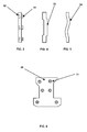
- Fig 3 and Fig 6 show detailed views of a preferred shim 30 embodiment where projections are stamped onto the surface of the shim 30 so as to be characterized by the projection 31 on one surface being inversely mirrored on the other surface as a depression 32 while the surrounding surface of the shim 30 remains unaffected by the stamping.
- the projection is ring shaped.
- the shape provides improved resistance against premature deformation of the projections during assembly compared to other preferred embodiments comprising coin or nipple shaped projections. This eliminates the need for further assembly steps such as the use of fitting paper tape on the surface of the shim 30 to prevent compression of the projections during installation.
- Fig 7 shows a shim 30 of the invention fitted between two blade roots 12 such that projections on the shim 30 preferentially contact the lateral face 14 of a blade root 12 thereby enabling preferential deformation of the projections when exposed to compressive stress
- Fig 4 shows another preferred embodiment of a shim 30 with projections where the projections are machined radially or tangentially on the surface of the shim 30 to form machined projections 33.
- projections take the form of one or more curve projections 34 where the projections are formed by for example bending of the shim 30.
- the curvature imparts spring to the shim 30 such that under compression the curvature is preferentially deformed in place of the shim itself. Due however to the curvature being less specific than for example stamped projections deformation is less specific resulting in a more global deformation.
- Projections are not however limited to those that are made by deforming the shim 30 in some way but can also include parts or portions fixed to the surface of the shim 30 so that they are raised from the surface of the shim. This enables this type of projection to sharing the attribute of preferential deformation.
- the projected parts or portions may or may not be made from the same material as the shim 30 and may take various shapes and forms.
- the process of manufacturing a shim 30 with stamp projections involves stamping of a manufactured shim 30 and then preferably pressing the stamped shim 30 where pressing involves pressing by flat pressing plates. This step ensures uniform, predefined shim thickness and is an alternative to ensuring uniformity in projection forming process.
Landscapes
- Engineering & Computer Science (AREA)
- Mechanical Engineering (AREA)
- General Engineering & Computer Science (AREA)
- Turbine Rotor Nozzle Sealing (AREA)
Abstract
The invention is based on the general idea of providing projections on the shim that preferentially deform. Accordingly, an aspect of the invention provides a shim (30) for a turbine wherein the turbine comprises a turbine blade with a blade root (12) and a rotor having a groove in which blade roots (12) can be circumferentially fitted so as to form fitted blade roots (12). The groove of the rotor includes a notch portion so as to form a hook portion for providing radial support for fitted blade roots (12) The shim (30), radially interspersable between lateral faces of fitted blade roots (12), has first and second surfaces that when fitted at least partially contact the lateral faces of fitted blade roots (12). The shim is characterized by at least one of the surfaces comprising at least one projection (31) such that in use compressive stresses on the shim concentrate on and preferentially deform the at least one projection.
Description
- The invention relates to shims fitted between turbine blade-roots where the blade-roots are circumferentially aligned in a grooved rotor.
- Fitting of turbine blades in circumferentially grooved rotors requires the use of shims interspersed between the lateral faces of blade roots. In operation the shims are exposed to compressive stresses caused for example by differing component thermal coefficients resulting in different component expansion rates during heat up and/or corrosion forming on either or both the shim or blade root after extended operation.
- The stresses can result in two failure modes. Where the shim is made of relatively soft material, oxide layer growth can cause creep deformation resulting in part of the shim being extruded into the process stream disrupting gas flow and ultimately leading to creep cracking of the shim. In a second failure mode, where the hardness of the shim is similar to that of the blade root, instead of the shim being deformed the ring-like assembly consisting of blades and shims can be forced outwardly in the circumferential direction stressing the hook section of the rotor that provides radial support for the root. This can lead to expensive rotor failure.
- In order to overcome the initial heat up stresses the minimum necessary clearance between shims and blade roots can be increased resulting in an initial looseness or "play". Further increasing of the clearance to overcome the problem of oxide formation only exacerbates the initial problem of play.
- As an alternative, to ameliorate the problem of corrosion-induced stress, shims can be treated to reduce their susceptibility to corrosion. This can be done by shot peening the surface or making them out of more corrosion resistance materials such as nickel alloys. These alternatives however only partially address the problem as for example in high temperature steam turbine operation where temperatures exceed 500°C corrosion rates are such that even the above methods do not completely stop the above mentioned failure modes from occurring.
- A further known problem of shims is that they must be manufactured to tight tolerances. As a result shims must be ground after manufacture in order to achieve the necessary tolerance adding to the cost and time of manufacture.
- The object of the invention is to provide a shim that addresses problems created by the stress of shims interspersed between turbine blade roots.
- This problem is solved by means of the subject matters of the independent claims. Advantageous embodiments are given in the dependant claims.
- The invention is based on the general idea of providing projections on the shim that preferentially deform. Accordingly, an aspect of the invention provides a shim for a turbine wherein the turbine comprises a turbine blade with a blade root and a rotor having a groove in which blade roots can be circumferentially fitted so as to form fitted blade roots. The groove of the rotor includes a notch portion so as to form a hook portion for providing radial support for fitted blade roots. The shim, radially interspersable between lateral faces of fitted blade roots, has first and second surfaces that when fitted at least partially contact the lateral faces of fitted blade roots. The shim is characterized by at least one of the surfaces comprising at least one projection such that in use compressive stresses on the shim concentrate on and preferentially deform the at least one projection.
- Due to the fact that projections localize stress peaks and as a consequence can more easily be deformed than other shim parts the shim can undergo significant strain without either extruding into the process or causing deformation of the hook section of the rotor groove. Also, initial play between blade roots and shims can be reduced as the shim can undergo greater levels of deformation without detrimental consequences.
- In another aspect of the invention the projections are inversely mirrored on the second surface so as to reduce the stress required to deform the projection and so improve the ability of the shim to preferentially deform. According to another aspect the first surface has more than one projection further enabling the designer to influence the location of peak stresses between the shim and blade root. In a yet further aspect of the invention the projection is a stamped projection, preferably having a ring shape. A ring-shaped projection provides greater rigidity than a simple nipple shaped coin projection and therefore has the advantage of reduced deformation likelihood during assembly. In a yet further aspect the projections are raised portions fixed to one or each of the surfaces of the shim providing a useful alternative to other types of projections.
- In yet another aspect of the invention the projection(s) are located proximal to an area of the shim that when fitted is proximal to the rotor notch, for example proximal to the "foot" region of the blade root. In this way stress build-up in both the rotor notch and the rotor hook portions is minimised reducing the potential for rotor failure.
- In yet a further aspect of the invention the shim is applied to a steam turbine operating at above 500°C corresponding to a region where corrosion potential is particularly high.
- Another aspect of the invention provides a method of manufacturing a shim suitable for installation between the lateral faces of a turbine blade root fitted into a circumferentially grooved rotor, including the step of stamping the shim such that a shim surface has a projection while another surface has an inversely mirrored depression. Preferably the method further includes the step of pressing the stamped shim so as to bring the stamped shim within a thickness tolerance. The relatively cheap and simple process of pressing replaces the relatively expensive step of grinding required to bring known shims into tolerance and over comes the problem of ensuring uniformity of the projections.
- It is a further object of the invention to overcome or at least ameliorate the disadvantages and shortcomings of the prior art or provide a useful alternative.
- Other objectives and advantages of the present invention will become apparent from the following description, taken in connection with the accompanying drawings wherein by way of illustration and example, an embodiment of the invention is disclosed.
- Throughout this text preferential deformation of a projection means the preferential reversal of the projection i.e. a stamped projection becomes "unstamped", a bent projection becomes "unbent", or a fitted part or machine projection becomes flattened. These events occur for example in preference to the general thinning or distortion of the shape of a shim, distortion of the blade root and/or the outward forcing in the circumferential direction of assembled blades and shims as a result of compressive stresses.
- By way of example, an embodiment of the invention is described more fully hereinafter with reference to the accompanying drawings, in which:
-
Figure 1 is a perspective view of a shim fitted between blade roots; -
Figure 2 is an axially cut view of a blade root fitted in a rotor; -
Figures 3-5 are side views of shims according to different embodiments of the invention; -
Figure 6 is a front view of the shim ofFigure 3 ; and -
Figure 7 is a perspective view of the shim ofFig 3 fitted between blade roots - Preferred embodiments of the present invention are now described with reference to the drawings, wherein like reference numerals are used to refer to like elements throughout. In the following description, for purposes of explanation, numerous specific details are set forth in order to provide a thorough understanding of the invention. It may be evident, however, that the invention may be practiced without these specific details.
-
Fig. 1 shows an arrangement for a high temperature steam turbine typical of one operating above 500°C although similar arrangements maybe used in other turbines. The arrangement comprisesblades 10 havingblade roots 12 suitable for fitting in a circumferentially groovedrotor 20 as shown inFig 2 where therotor 20 provides both radial and axial support for theblade root 12.Shims 30 are interspersed in the radial gap betweenlateral faces 14 of the fittedblade root 12. As seen inFig 1 the contact surfaces of theshim 30 match thelateral faces 14 of theblade root 12 and are essentially flat. -
Fig. 2 shows ablade root 12 fitted inside the grooved cavity of arotor 20 where the cavity is formed such that the rotor has ahook portion 22 and anotch portion 24. The fitting of thefeet portion 16 of theblade root 12 in therotor notch portion 24 enables therotor hook portion 22 to axially support theblade root 12. -
Fig 3 and Fig 6 show detailed views of a preferredshim 30 embodiment where projections are stamped onto the surface of theshim 30 so as to be characterized by theprojection 31 on one surface being inversely mirrored on the other surface as adepression 32 while the surrounding surface of theshim 30 remains unaffected by the stamping. In a preferred embodiment as shown inFig 3 and Fig 6 the projection is ring shaped. In this arrangement, while preferential deformation of the ring is possible, the shape provides improved resistance against premature deformation of the projections during assembly compared to other preferred embodiments comprising coin or nipple shaped projections. This eliminates the need for further assembly steps such as the use of fitting paper tape on the surface of theshim 30 to prevent compression of the projections during installation.Fig 7 shows ashim 30 of the invention fitted between twoblade roots 12 such that projections on theshim 30 preferentially contact thelateral face 14 of ablade root 12 thereby enabling preferential deformation of the projections when exposed to compressive stress -
Fig 4 shows another preferred embodiment of ashim 30 with projections where the projections are machined radially or tangentially on the surface of theshim 30 to formmachined projections 33. In yet another embodiment as seen inFig 5 , projections take the form of one ormore curve projections 34 where the projections are formed by for example bending of theshim 30. The curvature imparts spring to theshim 30 such that under compression the curvature is preferentially deformed in place of the shim itself. Due however to the curvature being less specific than for example stamped projections deformation is less specific resulting in a more global deformation. - Projections are not however limited to those that are made by deforming the
shim 30 in some way but can also include parts or portions fixed to the surface of theshim 30 so that they are raised from the surface of the shim. This enables this type of projection to sharing the attribute of preferential deformation. The projected parts or portions may or may not be made from the same material as theshim 30 and may take various shapes and forms. - The process of manufacturing a
shim 30 with stamp projections involves stamping of a manufacturedshim 30 and then preferably pressing the stampedshim 30 where pressing involves pressing by flat pressing plates. This step ensures uniform, predefined shim thickness and is an alternative to ensuring uniformity in projection forming process. - Although the invention has been herein shown and described in what is conceived to be the most practical and preferred embodiment, it is recognized that departures can be made within the scope of the invention, which is not to be limited to details described herein but is to be accorded the full scope of the appended claims so as to embrace any and all equivalent devices and apparatus. For example while an embodiment is described applicable to steam turbines, the invention could be applied to any turbine with blades roots interspaced with shims including gas turbines.
-
- 10. Blade
- 12. Blade root
- 14. Blade root lateral face
- 16. Blade root feet
- 20. Rotor
- 22. Rotor hook portion
- 24. Root notch portion
- 30. Shim
- 31. Stamped projection
- 32. Mirrored stamp depression
- 33. Machined projection
- 34. Curved projection
Claims (10)
- A shim for a turbine wherein said turbine comprises:turbine blades (10) having blade roots (12); anda rotor (20) having a groove for circumferentially fitting said blade roots to form fitted blade roots (12) wherein said groove includes a notch portion (24) so as to form a hook portion (22) for providing radial support for said fitted blade roots (12),wherein said shim (20) is radially interspersable between lateral faces (14) of said fitted blade roots (12) and has first and second surfaces that when fitted at least partially contact said lateral faces (14) of said fitted blade roots (12), said shim (30) characterized by at least one said surface comprising at least one projection such that in use compressive stresses on said shim (30) concentrate on and preferentially deform said at least one projection.
- The shim of claim 1 wherein at least one said projection on a said surface is inversely mirrored on the other said surface.
- The shim of claim 2 wherein said projection is a stamped projection (31)
- The shim of claim 3 wherein said or each projection is ring shaped.
- The shim of any one of claims 1 to 4 wherein at least one said projection is located on an area of the shim that in use is proximal to said rotor notch (24) so by minimizing stress build-up in both said rotor notch (24) and said rotor hook (22) portions
- The shim of any one of claims 1 to 5 wherein said first surface has more than one projection.
- The shim of any one of claims 1 to 4 wherein said turbine is a steam turbine operating at above 500°C.
- The shim of claim 1 wherein said at least one projection is a raised portion fixed to one or each said surface.
- A method of manufacturing a shim suitable for interspersing between the lateral faces (14) of a turbine blade root (12) fitted into a circumferential grooved rotor (20), including the step of stamping the shim (30) such that a shim (30) surface has a projection while another surface has an inversely mirrored depression (32).
- The method of claim 9 further including the step of pressing said stamped shim so as to bring said stamped shim within a thickness tolerance.
Priority Applications (1)
| Application Number | Priority Date | Filing Date | Title |
|---|---|---|---|
| EP08103676A EP2055897A1 (en) | 2008-04-23 | 2008-04-23 | Flexible Shims |
Applications Claiming Priority (1)
| Application Number | Priority Date | Filing Date | Title |
|---|---|---|---|
| EP08103676A EP2055897A1 (en) | 2008-04-23 | 2008-04-23 | Flexible Shims |
Publications (1)
| Publication Number | Publication Date |
|---|---|
| EP2055897A1 true EP2055897A1 (en) | 2009-05-06 |
Family
ID=40298683
Family Applications (1)
| Application Number | Title | Priority Date | Filing Date |
|---|---|---|---|
| EP08103676A Withdrawn EP2055897A1 (en) | 2008-04-23 | 2008-04-23 | Flexible Shims |
Country Status (1)
| Country | Link |
|---|---|
| EP (1) | EP2055897A1 (en) |
Cited By (4)
| Publication number | Priority date | Publication date | Assignee | Title |
|---|---|---|---|---|
| CH704617A1 (en) * | 2011-03-07 | 2012-09-14 | Alstom Technology Ltd | Blade assembly of a turbomachine. |
| CN103850715A (en) * | 2012-11-30 | 2014-06-11 | 西门子公司 | Rotor wheel disc |
| EP3293353A1 (en) * | 2016-09-13 | 2018-03-14 | Siemens Aktiengesellschaft | A technique for balancing of a rotor of a compressor for a gas turbine |
| WO2026008128A1 (en) * | 2024-07-01 | 2026-01-08 | GE Vernova Technology GmbH | Rotor for a steam turbine, steam turbine, power plant and method for mounting blades in a rotor for a steam turbine |
Citations (5)
| Publication number | Priority date | Publication date | Assignee | Title |
|---|---|---|---|---|
| DE495257C (en) * | 1926-12-11 | 1930-04-04 | Bbc Brown Boveri & Cie | Steam or gas turbine blading with blades and intermediate pieces inserted in the ring grooves of the wheels or drums |
| DE554119C (en) * | 1932-07-13 | Alfred Buechi Dipl Ing | Resilient blade attachment for gas and steam turbines | |
| DE1085643B (en) * | 1959-04-13 | 1960-07-21 | Ehrhardt & Sehmer Ag Maschf | Blade attachment in axial flow machines |
| EP0495586A1 (en) * | 1991-01-15 | 1992-07-22 | General Electric Company | Turbine blade wear protection system with multilayer shim |
| EP0520258A1 (en) * | 1991-06-28 | 1992-12-30 | Asea Brown Boveri Ag | System for keying rotor blades |
-
2008
- 2008-04-23 EP EP08103676A patent/EP2055897A1/en not_active Withdrawn
Patent Citations (5)
| Publication number | Priority date | Publication date | Assignee | Title |
|---|---|---|---|---|
| DE554119C (en) * | 1932-07-13 | Alfred Buechi Dipl Ing | Resilient blade attachment for gas and steam turbines | |
| DE495257C (en) * | 1926-12-11 | 1930-04-04 | Bbc Brown Boveri & Cie | Steam or gas turbine blading with blades and intermediate pieces inserted in the ring grooves of the wheels or drums |
| DE1085643B (en) * | 1959-04-13 | 1960-07-21 | Ehrhardt & Sehmer Ag Maschf | Blade attachment in axial flow machines |
| EP0495586A1 (en) * | 1991-01-15 | 1992-07-22 | General Electric Company | Turbine blade wear protection system with multilayer shim |
| EP0520258A1 (en) * | 1991-06-28 | 1992-12-30 | Asea Brown Boveri Ag | System for keying rotor blades |
Cited By (6)
| Publication number | Priority date | Publication date | Assignee | Title |
|---|---|---|---|---|
| CH704617A1 (en) * | 2011-03-07 | 2012-09-14 | Alstom Technology Ltd | Blade assembly of a turbomachine. |
| CN103850715A (en) * | 2012-11-30 | 2014-06-11 | 西门子公司 | Rotor wheel disc |
| EP3293353A1 (en) * | 2016-09-13 | 2018-03-14 | Siemens Aktiengesellschaft | A technique for balancing of a rotor of a compressor for a gas turbine |
| WO2018050467A1 (en) * | 2016-09-13 | 2018-03-22 | Siemens Aktiengesellschaft | A technique for balancing of a rotor of a compressor for a gas turbine |
| US10961852B2 (en) | 2016-09-13 | 2021-03-30 | Siemens Energy Global GmbH & Co. KG | Technique for low-speed balancing of a rotor of a compressor for a gas turbine |
| WO2026008128A1 (en) * | 2024-07-01 | 2026-01-08 | GE Vernova Technology GmbH | Rotor for a steam turbine, steam turbine, power plant and method for mounting blades in a rotor for a steam turbine |
Similar Documents
| Publication | Publication Date | Title |
|---|---|---|
| US7291946B2 (en) | Damper for stator assembly | |
| US9309939B2 (en) | Composite brake disc | |
| JP4049866B2 (en) | Turbine blade platform seal | |
| JP4726375B2 (en) | Brush seal | |
| US10215036B2 (en) | Blade attachment assembly | |
| US20100189562A1 (en) | Composite material turbomachine blade with a reinforced root | |
| CN101939509B (en) | Device for axially securing rotor blades in the rotor of a gas turbine | |
| CA2467810C (en) | Method of manufacturing a hollow blade for a turbine engine | |
| US20170211421A1 (en) | Vane, gas turbine, ring segment, remodeling method for vane, and remodeling method for ring segment | |
| EP2055897A1 (en) | Flexible Shims | |
| CN107869365A (en) | Turbocharger | |
| US10240474B2 (en) | Turbomachine having a seal device | |
| KR101656197B1 (en) | Method for manufacturing turbine rotor blade | |
| JP2023506429A (en) | Composite seal structure for machinery and method of manufacturing composite seal structure | |
| US7743498B2 (en) | Method of processing seals like leaf seals | |
| JP2009203981A (en) | Manufacturing method of rotor assembly for rotary vacuum pump | |
| US20110200440A1 (en) | Blade cluster having an offset axial mounting base | |
| US20150050135A1 (en) | Stator blade diaphragm ring, steam turbine and method | |
| US8894378B2 (en) | Systems, methods, and apparatus for sealing a bucket dovetail in a turbine | |
| US8128374B2 (en) | Securing element for fastening rotor blades | |
| CN108223379A (en) | Bearing set supporting rotor of screw compressor and compressor assembly method | |
| JP4775477B2 (en) | Turbocharger | |
| JP5011341B2 (en) | Manufacturing method of turbine rotor | |
| US20150003979A1 (en) | Steam turbine nozzle vane arrangement and method of manufacturing | |
| JP2015124717A (en) | Rotary machine blades and steam turbines |
Legal Events
| Date | Code | Title | Description |
|---|---|---|---|
| PUAI | Public reference made under article 153(3) epc to a published international application that has entered the european phase |
Free format text: ORIGINAL CODE: 0009012 |
|
| AK | Designated contracting states |
Kind code of ref document: A1 Designated state(s): AT BE BG CH CY CZ DE DK EE ES FI FR GB GR HR HU IE IS IT LI LT LU LV MC MT NL NO PL PT RO SE SI SK TR |
|
| AX | Request for extension of the european patent |
Extension state: AL BA MK RS |
|
| AKX | Designation fees paid | ||
| REG | Reference to a national code |
Ref country code: DE Ref legal event code: 8566 |
|
| STAA | Information on the status of an ep patent application or granted ep patent |
Free format text: STATUS: THE APPLICATION IS DEEMED TO BE WITHDRAWN |
|
| 18D | Application deemed to be withdrawn |
Effective date: 20091107 |