EP2055818A1 - Interlacing device - Google Patents
Interlacing device Download PDFInfo
- Publication number
- EP2055818A1 EP2055818A1 EP08013759A EP08013759A EP2055818A1 EP 2055818 A1 EP2055818 A1 EP 2055818A1 EP 08013759 A EP08013759 A EP 08013759A EP 08013759 A EP08013759 A EP 08013759A EP 2055818 A1 EP2055818 A1 EP 2055818A1
- Authority
- EP
- European Patent Office
- Prior art keywords
- yarn
- fluid
- interlacing
- groove
- injecting hole
- Prior art date
- Legal status (The legal status is an assumption and is not a legal conclusion. Google has not performed a legal analysis and makes no representation as to the accuracy of the status listed.)
- Granted
Links
Images






Classifications
-
- D—TEXTILES; PAPER
- D02—YARNS; MECHANICAL FINISHING OF YARNS OR ROPES; WARPING OR BEAMING
- D02J—FINISHING OR DRESSING OF FILAMENTS, YARNS, THREADS, CORDS, ROPES OR THE LIKE
- D02J1/00—Modifying the structure or properties resulting from a particular structure; Modifying, retaining, or restoring the physical form or cross-sectional shape, e.g. by use of dies or squeeze rollers
- D02J1/08—Interlacing constituent filaments without breakage thereof, e.g. by use of turbulent air streams
Definitions
- the present invention relates to a device that interlaces a multifilament yarn.
- the Japanese Patent No. 3034649 discloses a crimping device that entangles multifilament yarns with each other.
- the crimping device comprises a nozzle body portion 1 and a baffle body portion 2.
- a yarn passage 6 is formed to extend linearly through the nozzle body portion 1 and the baffle body portion 2.
- the yarn passage 6 communicates with a blow nozzle 7 provided in the nozzle body portion 1 and with an insertion slit 8.
- the insertion slit 8 is positioned between a flat surface of the nozzle body portion 1 and a flat surface of the baffle body portion 2.
- the yarn passage 6 is formed of a groove formed in the nozzle body portion 1 and comprising a first recessed wall surface 11 and a groove formed in the baffle body portion 2 and comprising a second recessed wall surface 12. See p. 3, 5th column, 11. 47 to 48 and 6th column, 11. 2 to 13, and Figure 4 in the Japanese Patent No. 3034649 .
- the insertion slit 8 is positioned close to the center of a cross section of the yarn passage 6. This is expected to pose various problems. That is, first, the yarn traveling close to the center of the cross section of the yarn passage 6 is likely to jump out through the insertion slit 8. Second, a fluid injected against the yarn through the blow nozzle 7 is likely to be blown out through the insertion slit 8.
- a main object of the present invention is to provide an interlacing device that can solve various problems resulting from a slit through which a yarn is inserted into a yarn traveling space.
- a first aspect of the present invention provides an interlacing device configured as follows. That is, the interlacing device comprises a first member having a first surface and a fluid injecting hole formed in the first surface so that a fluid is injected through the fluid injecting hole, and a second member having a second surface.
- the first surface and the second surface are arranged opposite each other to form a yarn traveling space as a space through which a yarn to be interlaced travels so that the yarn traveling space communicates with the fluid injecting hole and to form a yarn inserting gap as a gap through which the yarn can be inserted into the yarn traveling space in a direction perpendicular to a traveling direction of the yarn.
- a groove is formed in the second surface, and the groove and the first surface are combined together to form the yarn traveling space.
- the groove extends inward in a direction perpendicular to the second surface.
- the gap is located upstream of the fluid injected toward a groove bottom of the groove and away from the groove bottom of the groove.
- a second aspect of the present invention provides an interlacing device configured as follows. That is, the interlacing device comprises a first member having a first surface and a fluid injecting hole formed in the first surface so that a fluid is injected through the fluid injecting hole, and a second member having a second surface and a groove formed in the second surface.
- the first surface and the second surface are arranged opposite each other so as to combine the groove and the first surface together to form a yarn traveling space as a space through which a yarn to be interlaced travels so that the yarn traveling space communicates with the fluid injecting hole and to form a yarn inserting gap as a gap through which the yarn can be inserted into the yarn traveling space in a direction perpendicular to a traveling direction of the yarn.
- the groove extends inward in a direction perpendicular to the second surface.
- the gap is located upstream of the fluid injected toward a groove bottom of the groove and away from the groove bottom of the groove.
- a third aspect of the present invention provides an interlacing device configured as follows. That is, interlacing pieces each having a first surface and a second surface are provided in a row so that the first surface and second surface are arranged opposite each other. A fluid injecting hole is formed in the first surface of each of the interlacing pieces. A groove is formed in the second surface of each of the interlacing pieces.
- the first surface and the second surface are arranged opposite each other so as to combine the groove and the first surface together to form a yarn traveling space as a space through which a yarn to be interlaced travels so that the yarn traveling space communicates with the fluid injecting hole and to form a yarn inserting gap as a gap through which the yarn can be inserted into the yarn traveling space in a direction perpendicular to a traveling direction of the yarn.
- the groove extends inward in a direction perpendicular to the second surface. In the above-described configuration, the gap is located upstream of the fluid injected toward a groove bottom of the groove and away from the groove bottom of the groove.
- the above-described interlacing device is further configured as follows.
- the area in which the fluid injected into the yarn traveling space is mostly present or mostly flows is formed line-symmetrically with respect to the direction in which the fluid injecting hole is drilled. This arrangement enables the symmetric flow of the fluid in the area, which is expected to be useful for interlacing performance.
- the above-described interlacing device is further configured as follows.
- the fluid injecting hole is formed to have a cross section that is flat along the traveling direction of the yarn. This arrangement allows the fluid to be injected against the yarn traveling through the yarn traveling space, for a long time. This improves the interlacing performance.
- Figure 1 is a perspective view of an interlacing device according to the first embodiment of the present invention.
- An interlacing device 100 shown in Figure 1 is used to simultaneously interlace plural groups of a multifilament yarn Y.
- the interlacing device 100 is composed of a plurality of interlacing pieces 2 provided on a base 1 in a row, mounting bars 3 that fixes the interlacing pieces 2 to the base 1, and first yarn guides 4 and second yarn guides 5 which appropriately guide the multifilament yarn Y to the respective interlacing pieces 2.
- the mounting bars 3 are provided in pairs, and the interlacing pieces 2 are fixed to the base 1 via the pair of mounting bars 3.
- Arrow D shows a direction in which the multifilament yarn Y travels.
- Each of the first yarn guides 4 is located upstream of the corresponding multifilament yarn Y inserted through the corresponding interlacing piece 2.
- Each of the second yarn guides 5 is located downstream of the corresponding multifilament yarn Y inserted through the corresponding interlacing piece 2.
- the first yarn guides 4 and the second yarn guides 5 are supported on the base 1 by a method not shown in the drawings.
- a "yarn traveling direction” shown in Figure 1 indicates the direction in which the multifilament yarn Y travels.
- a “row direction” indicates a direction in which the plurality of interlacing pieces 2 are provided.
- a “slit direction” indicates a direction orthogonal to both the "yarn traveling direction” and the "row direction”.
- Figure 2 is a partly enlarged view of the interlacing device in Figure 1 .
- Figure 2 illustrates only a part of the base 1 and a pair of the adjacent interlacing pieces 2.
- a fluid channel 6 extending in the row direction is formed inside the base 1.
- the interlacing piece 2 has a first surface 7 and a second surface 8.
- the plurality of interlacing pieces 2 are provided in a row so that the first surface 7 and the second surface 8 are arranged opposite each other so as to abut partly against each other.
- Paired notches 9 in which the mounting bars 3 are partly accommodated are formed at a base end of the interlacing piece 2.
- the mounting bars 3 are inserted through the notches 9 and pushed toward the base 1 to fix the interlacing pieces 2 to the base 1.
- a fluid injecting hole 10 is formed in the first surface 7 of the interlacing piece 2 so that the fluid can be injected through the fluid injecting hole 10.
- a groove (hereinafter referred to as a yarn traveling groove 11) is formed in the second surface 8 of the interlacing piece 2.
- a first inclined surface 13 and a second inclined surface 14 are formed at a leading end of the interlacing piece 2 so as to guide the multifilament yarn Y into a slit 12 (yarn traveling gap).
- the first inclined surface 13 is inclined from the top 15 of the interlacing piece 2 toward the first surface 7.
- the second inclined surface 14 is inclined from the top 15 of the interlacing piece 2 toward the second surface 8.
- Figure 3 is a sectional view taken along line 3-3 in Figure 2 .
- the fluid injecting hole 10 is formed inside the interlacing piece 2 and communicates with a fluid supply path 16 that is open toward the base end.
- a fluid supply port 17 is open in the base 1 and communicates with the fluid supply path 16.
- Each of the interlacing pieces 2 is fixed to the base 1 so that the fluid supply port 16 and the fluid supply port 17 communicate with each other.
- a fluid supply device (not shown in the drawings) supplies a fluid to the fluid channel 6, the fluid is injected at a predetermined pressure and a predetermined flow rate through the fluid injecting hole 10 via the fluid supply port 17 and the fluid supply port 16 in this order.
- the fluid injecting hole 10 has a circular cross section as shown in Figure 2 .
- the yarn traveling groove 11 is formed to extend inward in a direction perpendicular to the second surface 8. That is, the yarn traveling groove 11 is formed to extend inward in the row direction.
- the yarn traveling groove 11 is linearly formed along the yarn traveling direction so as to penetrate the interlacing piece 2.
- the yarn traveling groove 11 is formed along a yarn path of the multifilament yarn Y.
- the first surface 7 and the second surface 8 are arranged opposite each other so as to combine the yarn traveling groove 11 and the first surface 7 together to form a yarn traveling space 18 such that the multifilament yarn Y to be interlaced travels through the yarn traveling space 18.
- the yarn traveling space 18 is schematically shown by an alternate long and two short dashes line.
- the yarn traveling space 18 communicates with the fluid injecting hole 10 in the adjacent interlacing piece 2.
- the yarn path of the multifilament yarn Y is set to lie inside a circular area shown by reference character S.
- mounting positions of the first yarn guide 4 and the second yarn guide 5, shown in Figure 1 are adjusted such that the yarn path of the multifilament yarn Y lies roughly inside the circular area S.
- the yarn traveling space 18 includes the circular area S, which is positioned inside the yarn traveling groove 11.
- the second surface 8 is divided into two parts by the yarn traveling groove 11, described above. That is, the second surface 8 is composed of a second surface leading end portion 8a located closer to the leading end of the interlacing piece 2 than the yarn traveling groove 11 and a second surface base end portion 8b located closer to the base end of the interlacing piece 2 than the yarn traveling groove 11.
- the second surface leading end portion 8a and the second surface base end portion 8b are parallel to each other but are not present in the same plane and are slightly displaced from each other in the row direction.
- the plurality of interlacing pieces 2 are arranged in a row so that the first surface 7 and the second surface 8 are arranged opposite each other so as to abut partly against each other.
- the first surface 7 abuts against the second surface base end portion 8b but not against the second surface leading end surface 8a.
- a slit 12 of thickness about 0.1 mm is formed between the first surface 7 and the second surface leading end portion 8a. The presence of the slit 12 allows the multifilament yarn Y to be inserted into the yarn traveling space 18 in a direction perpendicular to the yarn traveling direction.
- Figure 4 is an enlarged view of a part A in Figure 3 .
- the yarn traveling space 18 is composed of an opening 18a formed in the second surface 8 and an inner portion 18b formed inside the opening 18a.
- the yarn traveling space 18 is formed such that the inner portion 18b is thicker than the opening 18a in the slit direction. In this sense, the yarn traveling space 18 is said to extend inward.
- the contour of a cross section of the inner portion 18b of the yarn traveling space 18 is an oval composed of paired semicircles 19 and paired straight lines 20 joining the paired semicircles.
- the paired straight lines 20 extend in the slit direction.
- the paired semicircles 19 are located opposite each other in the slit direction.
- the inner portion 18b communicates with the opening 18a in the center of the inner portion 18b in the slit direction.
- the radius of the fluid injecting hole 10 is equal to a width defined by contours 18c, 18d of the opening 18 and which appear along the row direction in Figure 4 .
- the slit 12, connected to the yarn traveling space 18, is not connected directly to the inner portion 18b.
- the slit 12 is connected to the inner portion 18b via the opening 18a.
- the slit 12 is connected to the yarn traveling space 18 at a position located farthest from the inner portion 18b.
- the slit 12 is connected to the yarn traveling space 18 at the boundary between the fluid injecting hole 10 and the opening 18a.
- the inner portion 18b is line-symmetric with respect to a line C.
- the line C is parallel to the flow of a fluid passing through the fluid injecting hole 10 and overlaps the center of the circular area S.
- interlacing of the multifilament yarn Y is started.
- a fluid is supplied to the fluid channel 16 in the base 1, shown in Figure 2 .
- compressed air is used as the fluid.
- the traveling multifilament yarn Y is inserted into the slit 12 utilizing the first inclined surface 13 and the second inclined surface 14, shown in Figure 3 .
- the multifilament yarn Y traverses the opening 18a of the yarn traveling space 18 and is placed in the inner portion 18b of the yarn traveling space 18 (as shown in Figure 4 ).
- the multifilament yarn Y is guided by the appropriately positionally adjusted first yarn guide 4 and second yarn guide 5 so as to penetrate the circular area S.
- the fluid supplied to the fluid channel 6 in the base 1 is injected through the liquid injecting hole 10 via the liquid supply path 16 and the like.
- the fluid then traverses the opening 18a and is introduced into the inner portion 18b.
- the fluid introduced into the inner portion 18b collides against a groove bottom P of the yarn traveling groove 11, the contour of which is shown by the straight lines 20 in Figure 4 .
- the fluid then diverges toward side surfaces of the yarn traveling groove 11, the contour of which is shown by the paired semicircles 19.
- the side surfaces of the yarn traveling groove 11 interfere with the diverged fluid, which thus flows slightly spirally, while being discharged from the opposite ends of the yarn traveling groove 11 along the yarn path.
- the fluid introduced into the inner portion 18b is diverged twice along the slit direction and along the yarn traveling direction.
- the fluid injected into the yarn traveling space 18 is expected to be mostly present in the inner portion 18b and to flow mostly in the inner portion 18b.
- the above-described specific flow of the fluid allows the multifilament yarn Y traveling through the yarn traveling space 18 to be interlaced at predetermined intervals.
- the interlacing device 100 in the above-described embodiment is configured as follows.
- the interlacing pieces 2 each having the first surface 7 and the second surface 8 are provided in a row so that the first surface 7 and the second surface 8 are arranged opposite each other.
- the fluid injecting hole 10 is formed in the first surface 7 of each of the interlacing pieces 2 so that the fluid is injected through the fluid injecting hole 10.
- the yarn traveling groove 11 is formed in the second surface 8 of the interlacing piece 2.
- the first surface 7 and the second surface 8 are arranged opposite each other so as to combine the yarn traveling groove 11 and the first surface 7 together to form the yarn traveling space 18 as a space through which the multifilament yarn Y to be interlaced travels so that the yarn traveling space 18 communicates with the fluid injecting hole 10 and to form the slit 12 as a gap through which the multifilament yarn Y can be inserted into the yarn traveling space 18 in the direction perpendicular to the yarn traveling direction of the multifilament yarn Y.
- the yarn traveling groove 11 extends inward in the direction perpendicular to the second surface 8. In this configuration, the slit 12 is located upstream of the fluid injected toward the groove bottom P of the yarn traveling groove 11 and away from the groove bottom P of the yarn traveling groove 11.
- the availability of the sectional shape described in (2) enables the symmetric flow of the fluid in the area (inner portion 18b), which is expected to be useful for interlacing performance. Since the slit 12 is composed of the combination of the groove and the surface, the interlacing device 100 can be very easily manufactured.
- the inner portion 18b is formed line-symmetrically with respect to the line C.
- the flow of the fluid in the yarn traveling space 18 is expected to be formed line-symmetrically with respect to the line C.
- the present inventors expect that the fluid flow in the yarn traveling space 18 formed line-symmetrically with respect to the line C is technically significant. Additionally, such a line-symmetric sectional shape cannot be obtained by adopting the configuration in Japanese Patent No. 3034649 , described above.
- the interlacing device 100 is configured such that the large number of interlacing pieces 2 are provided in a row so as to allow the large number of multifilament yarns Y to be simultaneously interlaced.
- the interlacing device 100 may be configured so as to allow only the single multifilament yarn Y to be simultaneously interlaced. That is, the interlacing device 100 may be configured as described below.
- the interlacing device 100 comprises the interlacing piece 2 (first member) having the first surface 7 and the fluid injecting hole 10 formed in the first surface 7 so that the fluid is injected through the fluid injecting hole 10, and the interlacing piece 2 (second member) having the second surface 8 and the yarn traveling groove 11 formed in the second surface 8.
- the first surface 7 and the second surface 8 are arranged opposite each other so as to combine the yarn traveling groove 11 and the first surface 7 together to form the yarn traveling space 18 as a space through which the multifilament yarn Y to be interlaced travels so that the yarn traveling space 18 communicates with the fluid injecting hole 10 and to form the slit 12 as a gap through which the multifilament yarn Y can be inserted into the yarn traveling space 18 in the direction perpendicular to the yarn traveling direction of the multifilament yarn Y.
- the yarn traveling groove 11 extends inward in the direction perpendicular to the second surface 8. This configuration allows only the single multifilament yarn Y to be simultaneously interlaced, but can exert the above-described various effects.
- the interlacing piece 2 (first member) having the first surface 7 in which the fluid injecting hole 10 is formed need not have the second surface 8, described above.
- the interlacing piece 2 (second member) having the second surface 8 in which the yarn traveling groove 11 is formed need not have the first surface 7, described above.
- the number of interlacing pieces 2 provided on the base 1 in a row can be increased or reduced without limitation.
- the number may be two, three, four, or more.
- Figure 5 is similar to Figure 3 .
- the sectional shape of the inner portion 18b of the yarn traveling space 18 may be a circle that is line-symmetric with respect to the line C, instead of the shape according to the first embodiment, that is, the oval that is line-symmetric with respect to the line C.
- Figure 6 is similar to Figure 3 .
- the sectional shape of the inner portion 18b of the yarn traveling space 18 may be a trapezoid that is line-symmetric with respect to the line C, instead of the shape according to the first embodiment, that is, an oval that is line-symmetric with respect to the line C.
- the inner portion 18b shown in Figure 6 is shaped to be narrower toward the adjacent opening 18a. However, alternatively, the inner portion 18b may be shaped to be narrower away from the opening 18a.
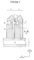
- Figure 7 is similar to Figure 3 .
- the inner portion 18b of the yarn traveling space 18 may have a sectional shape according to a fourth variation, that is, the sectional shape may be a trapezoid which is line-symmetric with respect to the line C and which has rounded sides.
- Figure 8 is similar to Figure 3 .
- the sectional shape of the inner portion 18b of the yarn traveling space 18 may be a combination of a trapezoid that is line-symmetric with respect to the line C and a rectangle that is line-symmetric with respect to the line C, instead of the shape according to the first embodiment, that is, the oval that is line-symmetric with respect to the line C.
- the trapezoid that is narrower toward the opening 18a is connected to the opening 18a, and the rectangle is positioned opposite the opening 18a across the trapezoid.
- the inner portion 18b may be such that the rectangle is connected to the opening 18a and such that the trapezoid is positioned opposite the opening 18a across the rectangle.
- Figure 9 is similar to Figure 2 and illustrates the second embodiment of the present invention. Duplicate descriptions of the first embodiment are appropriately omitted.
- the fluid injecting hole 10 has the circular cross section as shown in Figure 2 .
- the fluid injecting hole 10 has a cross section that is flat along the yarn traveling direction as shown in Figure 9 .
- the fluid injecting hole 10 according to the second embodiment is thick in the yarn traveling direction and thin in the slit direction.
- the opposite ends of the fluid injecting hole 10 in the yarn traveling direction are slightly rounded. That is, the fluid injecting hole 10 according to the present embodiment has an oval cross section.
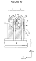
- Figure 10 is a sectional view which is similar to Figure 3 and which is taken along line 10-10 in Figure 9 .
- the width h1 of the fluid injecting hole 10 is smaller than the width h2 of the opening 18a of the yarn traveling space 18.
- Figure 11 is an enlarged view of a part A in Figure 10 and is similar to Figure 4 . As shown in Figure 11 , a fluid injected through the fluid injecting hole 10 collides against the groove bottom P of the yarn traveling groove 11 while maintaining the small width in the slit direction.
- the interlacing device 100 is further configured as described below. That is, the fluid injecting hole 10 is formed to be flat along the traveling direction of the multifilament yarn Y.
- the above-described configuration allows the fluid to be injected against the multifilament yarn Y traveling through the yarn traveling space 18, over a long time.
- Figure 12 is a graph showing the results of the tests for checking the interlacing device 100 according to the second embodiment for technical effects.
- the check tests are intended to verify the technical significance of the second embodiment compared to the first embodiment.
- the check tests focus particularly on the interlacing performance.
- a model 1 shows the interlacing device 100 according to the first embodiment.
- Models 2 and 3 are the interlacing devices 100 according to the second embodiment.
- the fluid injecting hole 10 in the model 1 had a circular cross section as described above; the circle had a diameter of 1.3 mm.
- the fluid injecting hole 10 in the model 2 had an oval cross section as described above; the paired semicircles constituting the oval each had a radius of 0.4 mm, and straight lines connecting the paired semicircles together each had a length of 1.0 mm.
- the fluid injecting hole 10 in the model 3 had an oval cross section as described above; the paired semicircles constituting the oval each had a radius of 0.3 mm, and straight lines connecting the paired semicircles together each had a length of 1.7 mm.
- the models 1, 2, and 3 were set to have the same sectional area so as to allow easy comparison of the technical effects.
- the types of multifilament yarns Y to be interlaced were PET, 83dtex, and 36 filaments.
- Yarn speed was set to 4,700 m/min.
- the axis of ordinate shows an interlace count as the number of interlaced portions formed on the multifilament yarn Y per unit meter.
- the axis of abscissa shows the flow rate of the fluid injected through the fluid injecting hole 10. Compressed air was adopted as the fluid.
- the interlacing performance is defined as (interface count/flow rate).
- Figure 12 shows that adoption of the models 2 according to the second embodiment allows a high interlace count to be achieved at the same flow rate and also allows the same interlace count to be achieved at a lower flow rate. That is, the models 2 and 3 exhibit a high interlacing performance.
- the interlacing device 100 shown in Figure 1 about 10,000 interlacing devices 100 are simultaneously used in one factory.
- the second modes 2 and 3 are very useful in terms of the performance of compressors that supply air to the interlacing devices 100.
- Figure 13 is similar to Figure 2 and illustrates the third embodiment of the present invention. Duplicate descriptions of the first embodiment are appropriately omitted.
- the second surface leading end portion 8a and the second surface base end portion 8b, constituting the second surface 8 are parallel to each other but are not present in the same plane.
- the second surface leading end portion 8a and the second surface base end portion 8b, constituting the second surface 8 are parallel to each other and are present in the same plane.
- the second surface 8 is entirely present in one plane.
- the yarn traveling space 18 shown in Figure 4 is not partly but entirely line-symmetric with respect to the line C.
- the slit 12 is formed between the first surface 7 and the second surface 8, arranged opposite each other. Furthermore, the first surface 7 and the second surface 8 abut partly against each other. In contrast, as shown in Figure 13 , in the present embodiment, a small gap (g) is created between the first surface 7 and the second surface 8 so as to form the slit 12.
- the small gap (g) has a width of, for example, 0.1 mm.
- the gap (g) is formed, for example, as follows. That is, when the plurality of interlacing pieces 2 are provided on the base 1 in a row, an appropriate thin piece 21 is interposed between the adjacent interlacing pieces 2. In other words, the interlacing pieces 2 and the thin pieces 21 are alternately juxtaposed on the base 1.
- the interlacing device 100 is configured as follows. That is, the slit 12 is formed by disposing the adjacent interlacing pieces 2 with the gap (g) created between the interlacing pieces 2.
- This configuration enables the following features to be simultaneously achieved: (a) the first surface 7 is present in one plane, (b) the second surface 8 is present in one plane, and (c) the slit 12 is formed between the first surface 7 and the second surface 8.
- the present embodiment is effective for reducing manufacturing costs compared to the first embodiment, in which the second surface 8 is separately present in a plane different from that in which the first surface 7 is present.
Landscapes
- Physics & Mathematics (AREA)
- Fluid Mechanics (AREA)
- Engineering & Computer Science (AREA)
- Textile Engineering (AREA)
- Yarns And Mechanical Finishing Of Yarns Or Ropes (AREA)
Abstract
Description
- The present invention relates to a device that interlaces a multifilament yarn.
- As a technique of this kind, the Japanese Patent No.
3034649 nozzle body portion 1 and abaffle body portion 2. Ayarn passage 6 is formed to extend linearly through thenozzle body portion 1 and thebaffle body portion 2. Theyarn passage 6 communicates with ablow nozzle 7 provided in thenozzle body portion 1 and with aninsertion slit 8. Theinsertion slit 8 is positioned between a flat surface of thenozzle body portion 1 and a flat surface of thebaffle body portion 2. Theyarn passage 6 is formed of a groove formed in thenozzle body portion 1 and comprising a first recessedwall surface 11 and a groove formed in thebaffle body portion 2 and comprising a second recessedwall surface 12. See p. 3, 5th column, 11. 47 to 48 and 6th column, 11. 2 to 13, andFigure 4 in the Japanese Patent No.3034649 - However, in the configuration disclosed in the Japanese Patent No.
3034649 insertion slit 8 is positioned close to the center of a cross section of theyarn passage 6. This is expected to pose various problems. That is, first, the yarn traveling close to the center of the cross section of theyarn passage 6 is likely to jump out through theinsertion slit 8. Second, a fluid injected against the yarn through theblow nozzle 7 is likely to be blown out through theinsertion slit 8. - The present invention has been made in view of the above-described problems. A main object of the present invention is to provide an interlacing device that can solve various problems resulting from a slit through which a yarn is inserted into a yarn traveling space.
- The problems to be solved by the present invention have been described above. Now, means for solving the problems and the effects thereof will be described.
- A first aspect of the present invention provides an interlacing device configured as follows. That is, the interlacing device comprises a first member having a first surface and a fluid injecting hole formed in the first surface so that a fluid is injected through the fluid injecting hole, and a second member having a second surface. The first surface and the second surface are arranged opposite each other to form a yarn traveling space as a space through which a yarn to be interlaced travels so that the yarn traveling space communicates with the fluid injecting hole and to form a yarn inserting gap as a gap through which the yarn can be inserted into the yarn traveling space in a direction perpendicular to a traveling direction of the yarn. A groove is formed in the second surface, and the groove and the first surface are combined together to form the yarn traveling space. The groove extends inward in a direction perpendicular to the second surface. In the above-described configuration, the gap is located upstream of the fluid injected toward a groove bottom of the groove and away from the groove bottom of the groove. Thus, effects (1) to (3) described below are exerted.
- (1) The yarn is unlikely to jump out through the gap.
- (2) An area in which the fluid injected into the yarn traveling space is mostly present or mostly flows may have a cross section that is line-symmetric with respect to a direction in which the fluid injecting hole is drilled.
- (3) The fluid is inhibited from being blown out through the gap. Since the groove is formed to extend inward, the effects (1) and (3) are more appropriately exerted. The availability of the sectional shape described in (2) enables the symmetric flow of the fluid in the area, which is expected to be useful for interlacing performance. Since the yarn traveling space is made up of the combination of the groove and the surface, the interlacing device can be very easily manufactured.
- A second aspect of the present invention provides an interlacing device configured as follows. That is, the interlacing device comprises a first member having a first surface and a fluid injecting hole formed in the first surface so that a fluid is injected through the fluid injecting hole, and a second member having a second surface and a groove formed in the second surface. The first surface and the second surface are arranged opposite each other so as to combine the groove and the first surface together to form a yarn traveling space as a space through which a yarn to be interlaced travels so that the yarn traveling space communicates with the fluid injecting hole and to form a yarn inserting gap as a gap through which the yarn can be inserted into the yarn traveling space in a direction perpendicular to a traveling direction of the yarn. The groove extends inward in a direction perpendicular to the second surface. In the above-described configuration, the gap is located upstream of the fluid injected toward a groove bottom of the groove and away from the groove bottom of the groove. Thus, effects (1) to (3) described below are exerted.
- (1) The yarn is unlikely to jump out through the gap.
- (2) An area in which the fluid injected into the yarn traveling space is mostly present or mostly flows may have a cross section that is line-symmetric with respect to a direction in which the fluid injecting hole is drilled.
- (3) The fluid is inhibited from being blown out through the gap. Since the groove is formed to extend inward, the effects (1) and (3) are more appropriately exerted. The availability of the sectional shape described in (2) enables the symmetric flow of the fluid in the area, which is expected to be useful for interlacing performance. Since the yarn traveling space is made up of the combination of the groove and the surface, the interlacing device can be very easily manufactured.
- A third aspect of the present invention provides an interlacing device configured as follows. That is, interlacing pieces each having a first surface and a second surface are provided in a row so that the first surface and second surface are arranged opposite each other. A fluid injecting hole is formed in the first surface of each of the interlacing pieces. A groove is formed in the second surface of each of the interlacing pieces. The first surface and the second surface are arranged opposite each other so as to combine the groove and the first surface together to form a yarn traveling space as a space through which a yarn to be interlaced travels so that the yarn traveling space communicates with the fluid injecting hole and to form a yarn inserting gap as a gap through which the yarn can be inserted into the yarn traveling space in a direction perpendicular to a traveling direction of the yarn. The groove extends inward in a direction perpendicular to the second surface. In the above-described configuration, the gap is located upstream of the fluid injected toward a groove bottom of the groove and away from the groove bottom of the groove. Thus, effects (1) to (3) described below are exerted.
- (1) The yarn is unlikely to jump out through the gap.
- (2) An area in which the fluid injected into the yarn traveling space is mostly present or mostly flows may have a cross section that is line-symmetric with respect to a direction in which the fluid injecting hole is drilled.
- (3) The fluid is inhibited from being blown out through the gap. Since the groove is formed to extend inward, the effects (1) and (3) are more appropriately exerted. The availability of the sectional shape described in (2) enables the symmetric flow of the fluid in the area, which is expected to be useful for interlacing performance. Since the yarn traveling space is made up of the combination of the groove and the surface, the interlacing device can be very easily manufactured.
- The above-described interlacing device is further configured as follows. The area in which the fluid injected into the yarn traveling space is mostly present or mostly flows is formed line-symmetrically with respect to the direction in which the fluid injecting hole is drilled. This arrangement enables the symmetric flow of the fluid in the area, which is expected to be useful for interlacing performance.
- The above-described interlacing device is further configured as follows. The fluid injecting hole is formed to have a cross section that is flat along the traveling direction of the yarn. This arrangement allows the fluid to be injected against the yarn traveling through the yarn traveling space, for a long time. This improves the interlacing performance.
- Other features, elements, processes, steps, characteristics and advantages of the present invention will become more apparent from the following detailed description of preferred embodiments of the present invention with reference to the attached drawings.
-
-
Figure 1 is a perspective view of an interlacing device according to an embodiment of the present invention. -
Figure 2 is a partly enlarged view of the interlacing device inFigure 1 . -
Figure 3 is a sectional view taken along line 3-3 inFigure 2 . -
Figure 4 is an enlarged view of a part A inFigure 3 . -
Figure 5 is a diagram similar toFigure 3 . -
Figure 6 is a diagram similar toFigure 3 . -
Figure 7 is a diagram similar toFigure 3 . -
Figure 8 is a diagram similar toFigure 3 . -
Figure 9 is a diagram which is similar toFigure 2 and which illustrates a second embodiment of the present invention. -
Figure 10 is a diagram which is similar toFigure 3 and which is taken along line 10-10 inFigure 9 . -
Figure 11 is an enlarged view of a part A inFigure 10 , which is similar toFigure 4 . -
Figure 12 is a graph showing results of tests for checking an interlacing device according to a second embodiment for technical effects. -
Figure 13 is a diagram which is similar toFigure 2 and which illustrates a third embodiment of the present invention. - A first embodiment of the present invention will be described below with reference to the drawings.
Figure 1 is a perspective view of an interlacing device according to the first embodiment of the present invention. - An interlacing
device 100 shown inFigure 1 is used to simultaneously interlace plural groups of a multifilament yarn Y. The interlacingdevice 100 is composed of a plurality of interlacingpieces 2 provided on abase 1 in a row, mountingbars 3 that fixes the interlacingpieces 2 to thebase 1, and first yarn guides 4 and second yarn guides 5 which appropriately guide the multifilament yarn Y to the respective interlacingpieces 2. The mounting bars 3 are provided in pairs, and the interlacingpieces 2 are fixed to thebase 1 via the pair of mountingbars 3. Arrow D shows a direction in which the multifilament yarn Y travels. Each of the first yarn guides 4 is located upstream of the corresponding multifilament yarn Y inserted through thecorresponding interlacing piece 2. Each of the second yarn guides 5 is located downstream of the corresponding multifilament yarn Y inserted through thecorresponding interlacing piece 2. The first yarn guides 4 and the second yarn guides 5 are supported on thebase 1 by a method not shown in the drawings. A "yarn traveling direction" shown inFigure 1 indicates the direction in which the multifilament yarn Y travels. Similarly, a "row direction" indicates a direction in which the plurality of interlacingpieces 2 are provided. A "slit direction" indicates a direction orthogonal to both the "yarn traveling direction" and the "row direction". - Now, the configuration of the
base 1 and the interlacingpiece 2 will be described in detail. SeeFigure 2. Figure 2 is a partly enlarged view of the interlacing device inFigure 1 . For convenience of description,Figure 2 illustrates only a part of thebase 1 and a pair of the adjacent interlacingpieces 2. - As shown in
Figure 2 , afluid channel 6 extending in the row direction is formed inside thebase 1. - The interlacing
piece 2 has afirst surface 7 and asecond surface 8. The plurality of interlacingpieces 2 are provided in a row so that thefirst surface 7 and thesecond surface 8 are arranged opposite each other so as to abut partly against each other. Pairednotches 9 in which the mountingbars 3 are partly accommodated are formed at a base end of the interlacingpiece 2. The mounting bars 3 are inserted through thenotches 9 and pushed toward thebase 1 to fix the interlacingpieces 2 to thebase 1. Afluid injecting hole 10 is formed in thefirst surface 7 of the interlacingpiece 2 so that the fluid can be injected through thefluid injecting hole 10. A groove (hereinafter referred to as a yarn traveling groove 11) is formed in thesecond surface 8 of the interlacingpiece 2. A firstinclined surface 13 and a secondinclined surface 14 are formed at a leading end of the interlacingpiece 2 so as to guide the multifilament yarn Y into a slit 12 (yarn traveling gap). The firstinclined surface 13 is inclined from the top 15 of the interlacingpiece 2 toward thefirst surface 7. The secondinclined surface 14 is inclined from the top 15 of the interlacingpiece 2 toward thesecond surface 8. -
Figure 3 is a sectional view taken along line 3-3 inFigure 2 . As shown inFigure 3 , thefluid injecting hole 10 is formed inside the interlacingpiece 2 and communicates with afluid supply path 16 that is open toward the base end. Afluid supply port 17 is open in thebase 1 and communicates with thefluid supply path 16. Each of the interlacingpieces 2 is fixed to thebase 1 so that thefluid supply port 16 and thefluid supply port 17 communicate with each other. In this configuration, when a fluid supply device (not shown in the drawings) supplies a fluid to thefluid channel 6, the fluid is injected at a predetermined pressure and a predetermined flow rate through thefluid injecting hole 10 via thefluid supply port 17 and thefluid supply port 16 in this order. In the present embodiment, thefluid injecting hole 10 has a circular cross section as shown inFigure 2 . - As shown in
Figures 1 to 3 , theyarn traveling groove 11 is formed to extend inward in a direction perpendicular to thesecond surface 8. That is, theyarn traveling groove 11 is formed to extend inward in the row direction. Theyarn traveling groove 11 is linearly formed along the yarn traveling direction so as to penetrate theinterlacing piece 2. In other words, theyarn traveling groove 11 is formed along a yarn path of the multifilament yarn Y. As shown inFigure 3 , thefirst surface 7 and thesecond surface 8 are arranged opposite each other so as to combine theyarn traveling groove 11 and thefirst surface 7 together to form ayarn traveling space 18 such that the multifilament yarn Y to be interlaced travels through theyarn traveling space 18. InFigure 3 , theyarn traveling space 18 is schematically shown by an alternate long and two short dashes line. Theyarn traveling space 18 communicates with thefluid injecting hole 10 in theadjacent interlacing piece 2. InFigure 3 , the yarn path of the multifilament yarn Y is set to lie inside a circular area shown by reference character S. In other words, mounting positions of the first yarn guide 4 and thesecond yarn guide 5, shown inFigure 1 , are adjusted such that the yarn path of the multifilament yarn Y lies roughly inside the circular area S. Additionally, theyarn traveling space 18 includes the circular area S, which is positioned inside theyarn traveling groove 11. - As shown in
Figure 3 , thesecond surface 8 is divided into two parts by theyarn traveling groove 11, described above. That is, thesecond surface 8 is composed of a second surface leadingend portion 8a located closer to the leading end of the interlacingpiece 2 than theyarn traveling groove 11 and a second surfacebase end portion 8b located closer to the base end of the interlacingpiece 2 than theyarn traveling groove 11. The second surface leadingend portion 8a and the second surfacebase end portion 8b are parallel to each other but are not present in the same plane and are slightly displaced from each other in the row direction. As described above, the plurality of interlacingpieces 2 are arranged in a row so that thefirst surface 7 and thesecond surface 8 are arranged opposite each other so as to abut partly against each other. Specifically, with the plurality of interlacingpieces 2 provided on thebase 1 in a row, thefirst surface 7 abuts against the second surfacebase end portion 8b but not against the second surface leadingend surface 8a. With thefirst surface 7 and thesecond surface 8 thus arranged opposite each other, aslit 12 of thickness about 0.1 mm is formed between thefirst surface 7 and the second surface leadingend portion 8a. The presence of theslit 12 allows the multifilament yarn Y to be inserted into theyarn traveling space 18 in a direction perpendicular to the yarn traveling direction. -
Figure 4 is an enlarged view of a part A inFigure 3 . As shown inFigure 4 , theyarn traveling space 18 is composed of anopening 18a formed in thesecond surface 8 and aninner portion 18b formed inside theopening 18a. In a cross section shown inFigure 4 , theyarn traveling space 18 is formed such that theinner portion 18b is thicker than theopening 18a in the slit direction. In this sense, theyarn traveling space 18 is said to extend inward. The contour of a cross section of theinner portion 18b of theyarn traveling space 18 is an oval composed of pairedsemicircles 19 and pairedstraight lines 20 joining the paired semicircles. The pairedstraight lines 20 extend in the slit direction. The pairedsemicircles 19 are located opposite each other in the slit direction. Theinner portion 18b communicates with theopening 18a in the center of theinner portion 18b in the slit direction. In the present embodiment, the radius of thefluid injecting hole 10 is equal to a width defined bycontours opening 18 and which appear along the row direction inFigure 4 . Theslit 12, connected to theyarn traveling space 18, is not connected directly to theinner portion 18b. Theslit 12 is connected to theinner portion 18b via theopening 18a. Theslit 12 is connected to theyarn traveling space 18 at a position located farthest from theinner portion 18b. Theslit 12 is connected to theyarn traveling space 18 at the boundary between thefluid injecting hole 10 and theopening 18a. Theinner portion 18b is line-symmetric with respect to a line C. The line C is parallel to the flow of a fluid passing through thefluid injecting hole 10 and overlaps the center of the circular area S. - In the above-described configuration, interlacing of the multifilament yarn Y is started. First, a fluid is supplied to the
fluid channel 16 in thebase 1, shown inFigure 2 . For example, compressed air is used as the fluid. Then, the traveling multifilament yarn Y is inserted into theslit 12 utilizing the firstinclined surface 13 and the secondinclined surface 14, shown inFigure 3 . Thus, the multifilament yarn Y traverses theopening 18a of theyarn traveling space 18 and is placed in theinner portion 18b of the yarn traveling space 18 (as shown inFigure 4 ). Specifically, the multifilament yarn Y is guided by the appropriately positionally adjusted first yarn guide 4 andsecond yarn guide 5 so as to penetrate the circular area S. - The fluid supplied to the
fluid channel 6 in thebase 1 is injected through theliquid injecting hole 10 via theliquid supply path 16 and the like. The fluid then traverses theopening 18a and is introduced into theinner portion 18b. The fluid introduced into theinner portion 18b collides against a groove bottom P of theyarn traveling groove 11, the contour of which is shown by thestraight lines 20 inFigure 4 . The fluid then diverges toward side surfaces of theyarn traveling groove 11, the contour of which is shown by the pairedsemicircles 19. Then, the side surfaces of theyarn traveling groove 11 interfere with the diverged fluid, which thus flows slightly spirally, while being discharged from the opposite ends of theyarn traveling groove 11 along the yarn path. In short, the fluid introduced into theinner portion 18b is diverged twice along the slit direction and along the yarn traveling direction. The fluid injected into theyarn traveling space 18 is expected to be mostly present in theinner portion 18b and to flow mostly in theinner portion 18b. - The above-described specific flow of the fluid allows the multifilament yarn Y traveling through the
yarn traveling space 18 to be interlaced at predetermined intervals. - As described above, the interlacing
device 100 in the above-described embodiment is configured as follows. The interlacingpieces 2 each having thefirst surface 7 and thesecond surface 8 are provided in a row so that thefirst surface 7 and thesecond surface 8 are arranged opposite each other. Thefluid injecting hole 10 is formed in thefirst surface 7 of each of the interlacingpieces 2 so that the fluid is injected through thefluid injecting hole 10. Theyarn traveling groove 11 is formed in thesecond surface 8 of the interlacingpiece 2. Thefirst surface 7 and thesecond surface 8 are arranged opposite each other so as to combine theyarn traveling groove 11 and thefirst surface 7 together to form theyarn traveling space 18 as a space through which the multifilament yarn Y to be interlaced travels so that theyarn traveling space 18 communicates with thefluid injecting hole 10 and to form theslit 12 as a gap through which the multifilament yarn Y can be inserted into theyarn traveling space 18 in the direction perpendicular to the yarn traveling direction of the multifilament yarn Y. Theyarn traveling groove 11 extends inward in the direction perpendicular to thesecond surface 8. In this configuration, theslit 12 is located upstream of the fluid injected toward the groove bottom P of theyarn traveling groove 11 and away from the groove bottom P of theyarn traveling groove 11. Thus, effects (1) to (3) described below are exerted. - (1) The multifilament yarn Y is unlikely to jump out through the
slit 12. - (2) The area in which the fluid injected into the
yarn traveling space 18 is mostly present or mostly flows may have a cross section that is line-symmetric with respect to the direction in which thefluid injecting hole 10 is drilled. In other words, the area may have a cross section that is line-symmetric with respect to the line C in theinner portion 18b. - (3) The fluid is inhibited from being blown out through the
slit 12. Since theyarn traveling groove 11 is formed to extend inward, the effects (1) and (3) are more appropriately exerted. - The availability of the sectional shape described in (2) enables the symmetric flow of the fluid in the area (
inner portion 18b), which is expected to be useful for interlacing performance. Since theslit 12 is composed of the combination of the groove and the surface, the interlacingdevice 100 can be very easily manufactured. - Of special note is that the
inner portion 18b is formed line-symmetrically with respect to the line C. Thus, the flow of the fluid in theyarn traveling space 18 is expected to be formed line-symmetrically with respect to the line C. The present inventors expect that the fluid flow in theyarn traveling space 18 formed line-symmetrically with respect to the line C is technically significant. Additionally, such a line-symmetric sectional shape cannot be obtained by adopting the configuration in Japanese Patent No.3034649 - The preferred embodiment of the present invention has been described. However, the above-described embodiment can be varied as described below.
- In the above-described first embodiment, the interlacing
device 100 is configured such that the large number of interlacingpieces 2 are provided in a row so as to allow the large number of multifilament yarns Y to be simultaneously interlaced. Alternatively, the interlacingdevice 100 may be configured so as to allow only the single multifilament yarn Y to be simultaneously interlaced. That is, the interlacingdevice 100 may be configured as described below. - The interlacing
device 100 comprises the interlacing piece 2 (first member) having thefirst surface 7 and thefluid injecting hole 10 formed in thefirst surface 7 so that the fluid is injected through thefluid injecting hole 10, and the interlacing piece 2 (second member) having thesecond surface 8 and theyarn traveling groove 11 formed in thesecond surface 8. Thefirst surface 7 and thesecond surface 8 are arranged opposite each other so as to combine theyarn traveling groove 11 and thefirst surface 7 together to form theyarn traveling space 18 as a space through which the multifilament yarn Y to be interlaced travels so that theyarn traveling space 18 communicates with thefluid injecting hole 10 and to form theslit 12 as a gap through which the multifilament yarn Y can be inserted into theyarn traveling space 18 in the direction perpendicular to the yarn traveling direction of the multifilament yarn Y. Theyarn traveling groove 11 extends inward in the direction perpendicular to thesecond surface 8. This configuration allows only the single multifilament yarn Y to be simultaneously interlaced, but can exert the above-described various effects. - In the first variation, the interlacing piece 2 (first member) having the
first surface 7 in which thefluid injecting hole 10 is formed need not have thesecond surface 8, described above. Similarly, the interlacing piece 2 (second member) having thesecond surface 8 in which theyarn traveling groove 11 is formed need not have thefirst surface 7, described above. - In the above-described first embodiment, the number of interlacing
pieces 2 provided on thebase 1 in a row can be increased or reduced without limitation. For example, the number may be two, three, four, or more. -
Figure 5 is similar toFigure 3 . As shown inFigure 5 , the sectional shape of theinner portion 18b of theyarn traveling space 18 may be a circle that is line-symmetric with respect to the line C, instead of the shape according to the first embodiment, that is, the oval that is line-symmetric with respect to the line C. -
Figure 6 is similar toFigure 3 . As shown inFigure 6 , the sectional shape of theinner portion 18b of theyarn traveling space 18 may be a trapezoid that is line-symmetric with respect to the line C, instead of the shape according to the first embodiment, that is, an oval that is line-symmetric with respect to the line C. Theinner portion 18b shown inFigure 6 is shaped to be narrower toward theadjacent opening 18a. However, alternatively, theinner portion 18b may be shaped to be narrower away from theopening 18a. -
Figure 7 is similar toFigure 3 . As shown inFigure 7 , theinner portion 18b of theyarn traveling space 18 may have a sectional shape according to a fourth variation, that is, the sectional shape may be a trapezoid which is line-symmetric with respect to the line C and which has rounded sides. -
Figure 8 is similar toFigure 3 . As shown inFigure 8 , the sectional shape of theinner portion 18b of theyarn traveling space 18 may be a combination of a trapezoid that is line-symmetric with respect to the line C and a rectangle that is line-symmetric with respect to the line C, instead of the shape according to the first embodiment, that is, the oval that is line-symmetric with respect to the line C. In theinner portion 18b shown inFigure 8 , the trapezoid that is narrower toward theopening 18a is connected to theopening 18a, and the rectangle is positioned opposite theopening 18a across the trapezoid. Of course, alternatively, theinner portion 18b may be such that the rectangle is connected to theopening 18a and such that the trapezoid is positioned opposite theopening 18a across the rectangle. - Now, a second embodiment of the present invention will be described.
Figure 9 is similar toFigure 2 and illustrates the second embodiment of the present invention. Duplicate descriptions of the first embodiment are appropriately omitted. - In the first embodiment, the
fluid injecting hole 10 has the circular cross section as shown inFigure 2 . In contrast, in the present embodiment, thefluid injecting hole 10 has a cross section that is flat along the yarn traveling direction as shown inFigure 9 . Specifically, compared to thefluid injecting hole 10 according to the first embodiment, thefluid injecting hole 10 according to the second embodiment is thick in the yarn traveling direction and thin in the slit direction. The opposite ends of thefluid injecting hole 10 in the yarn traveling direction are slightly rounded. That is, thefluid injecting hole 10 according to the present embodiment has an oval cross section. -
Figure 10 is a sectional view which is similar toFigure 3 and which is taken along line 10-10 inFigure 9 . In the slit direction inFigure 10 , the width h1 of thefluid injecting hole 10 is smaller than the width h2 of theopening 18a of theyarn traveling space 18. -
Figure 11 is an enlarged view of a part A inFigure 10 and is similar toFigure 4 . As shown inFigure 11 , a fluid injected through thefluid injecting hole 10 collides against the groove bottom P of theyarn traveling groove 11 while maintaining the small width in the slit direction. - As described above, in the above-described embodiment, the interlacing
device 100 is further configured as described below. That is, thefluid injecting hole 10 is formed to be flat along the traveling direction of the multifilament yarn Y. The above-described configuration allows the fluid to be injected against the multifilament yarn Y traveling through theyarn traveling space 18, over a long time. - Now, tests for checking the interlacing
device 100 according to the second embodiment for technical effects will be described.Figure 12 is a graph showing the results of the tests for checking the interlacingdevice 100 according to the second embodiment for technical effects. The check tests are intended to verify the technical significance of the second embodiment compared to the first embodiment. The check tests focus particularly on the interlacing performance. - First, test conditions will be described. A
model 1 shows the interlacingdevice 100 according to the first embodiment.Models devices 100 according to the second embodiment. Thefluid injecting hole 10 in themodel 1 had a circular cross section as described above; the circle had a diameter of 1.3 mm. Thefluid injecting hole 10 in themodel 2 had an oval cross section as described above; the paired semicircles constituting the oval each had a radius of 0.4 mm, and straight lines connecting the paired semicircles together each had a length of 1.0 mm. Similarly, thefluid injecting hole 10 in themodel 3 had an oval cross section as described above; the paired semicircles constituting the oval each had a radius of 0.3 mm, and straight lines connecting the paired semicircles together each had a length of 1.7 mm. In short, themodels - The types of multifilament yarns Y to be interlaced were PET, 83dtex, and 36 filaments. Yarn speed was set to 4,700 m/min. In
Figure 12 , the axis of ordinate shows an interlace count as the number of interlaced portions formed on the multifilament yarn Y per unit meter. The axis of abscissa shows the flow rate of the fluid injected through thefluid injecting hole 10. Compressed air was adopted as the fluid. In the specification, the interlacing performance is defined as (interface count/flow rate). -
Figure 12 shows that adoption of themodels 2 according to the second embodiment allows a high interlace count to be achieved at the same flow rate and also allows the same interlace count to be achieved at a lower flow rate. That is, themodels device 100 shown inFigure 1 , about 10,000 interlacingdevices 100 are simultaneously used in one factory. Thus, as is understood from the test results, thesecond modes devices 100. - Now, a third embodiment of the present invention will be described with reference to the drawings.
Figure 13 is similar toFigure 2 and illustrates the third embodiment of the present invention. Duplicate descriptions of the first embodiment are appropriately omitted. - As shown in
Figure 3 , in the first embodiment, the second surface leadingend portion 8a and the second surfacebase end portion 8b, constituting thesecond surface 8, are parallel to each other but are not present in the same plane. In contrast, as shown inFigure 13 , in the present embodiment, the second surface leadingend portion 8a and the second surfacebase end portion 8b, constituting thesecond surface 8, are parallel to each other and are present in the same plane. In other words, thesecond surface 8 is entirely present in one plane. Thus, in the present embodiment, theyarn traveling space 18 shown inFigure 4 is not partly but entirely line-symmetric with respect to the line C. - Furthermore, as shown in
Figure 2 , in the present embodiment, theslit 12 is formed between thefirst surface 7 and thesecond surface 8, arranged opposite each other. Furthermore, thefirst surface 7 and thesecond surface 8 abut partly against each other. In contrast, as shown inFigure 13 , in the present embodiment, a small gap (g) is created between thefirst surface 7 and thesecond surface 8 so as to form theslit 12. The small gap (g) has a width of, for example, 0.1 mm. The gap (g) is formed, for example, as follows. That is, when the plurality of interlacingpieces 2 are provided on thebase 1 in a row, an appropriatethin piece 21 is interposed between the adjacent interlacingpieces 2. In other words, the interlacingpieces 2 and thethin pieces 21 are alternately juxtaposed on thebase 1. - As described above, in the present embodiment, the interlacing
device 100 is configured as follows. That is, theslit 12 is formed by disposing the adjacent interlacingpieces 2 with the gap (g) created between the interlacingpieces 2. This configuration enables the following features to be simultaneously achieved: (a) thefirst surface 7 is present in one plane, (b) thesecond surface 8 is present in one plane, and (c) theslit 12 is formed between thefirst surface 7 and thesecond surface 8. Moreover, when focus is placed on the point that the features (a) and (b) are simultaneously achieved, the present embodiment is effective for reducing manufacturing costs compared to the first embodiment, in which thesecond surface 8 is separately present in a plane different from that in which thefirst surface 7 is present. - While the present invention has been described with respect to preferred embodiments thereof, it will be apparent to those skilled in the art that the disclosed invention may be modified in numerous ways and may assume many embodiments other than those specifically set out and described above. Accordingly, it is intented by the appended claims to cover all modifications of the present invention that fall within the true spirit and scope of the invention.
Claims (5)
- An interlacing device comprising a first member having a first surface and a fluid injecting hole formed in the first surface so that a fluid is injected through the fluid injecting hole, and a second member having a second surface, the first surface and the second surface being arranged opposite each other to form a yarn traveling space as a space through which a yarn to be interlaced travels so that the yarn traveling space communicates with the fluid injecting hole and to form a yarn inserting gap as a gap through which the yarn can be inserted into the yarn traveling space in a direction perpendicular to a traveling direction of the yarn, the device being characterized in that:a groove is formed in the second surface, and the groove and the first surface are combined to form the yarn traveling space, andthe groove extends inward in a direction perpendicular to the second surface.
- An interlacing device characterized by comprising:a first member having a first surface and a fluid injecting hole formed in the first surface so that a fluid is injected through the fluid injecting hole; anda second member having a second surface and a groove formed in the second surface,the first surface and the second surface being arranged opposite each other so as to combine the groove and the first surface together to form a yarn traveling space as a space through which a yarn to be interlaced travels so that the yarn traveling space communicates with the fluid injecting hole and to form a yarn inserting gap as a gap through which the yarn can be inserted into the yarn traveling space in a direction perpendicular to a traveling direction of the yarn, andthe groove extending inward in a direction perpendicular to the second surface.
- An interlacing device characterized in that:interlacing pieces each having a first surface and a second surface are provided in a row so that the first surface and the second surface are arranged opposite each other,a fluid injecting hole is formed in the first surface of each of the interlacing pieces,a groove is formed in the second surface of each of the interlacing pieces,the first surface and the second surface are arranged opposite each other so as to combine the groove and the first surface together to form a yarn traveling space as a space through which a yarn to be interlaced travels so that the yarn traveling space communicates with the fluid injecting hole and to form a yarn inserting gap as a gap through which the yarn can be inserted into the yarn traveling space in a direction perpendicular to a traveling direction of the yarn, andthe groove extends inward in a direction perpendicular to the second surface.
- An interlacing device according to any one of Claim I to Claim 3, characterized in that an area in which the fluid injected into the yarn traveling space is mostly present or mostly flows is formed line-symmetrically with respect to a direction in which the fluid injecting hole is drilled.
- An interlacing device according to any one of Claim 1 to Claim 4, characterized in that the fluid injecting hole is formed to have a cross section that is flat along the traveling direction of the yarn.
Applications Claiming Priority (1)
| Application Number | Priority Date | Filing Date | Title |
|---|---|---|---|
| JP2007281996A JP4673355B2 (en) | 2007-10-30 | 2007-10-30 | Confounding device |
Publications (2)
| Publication Number | Publication Date |
|---|---|
| EP2055818A1 true EP2055818A1 (en) | 2009-05-06 |
| EP2055818B1 EP2055818B1 (en) | 2012-02-15 |
Family
ID=40344653
Family Applications (1)
| Application Number | Title | Priority Date | Filing Date |
|---|---|---|---|
| EP20080013759 Active EP2055818B1 (en) | 2007-10-30 | 2008-07-31 | Interlacing device |
Country Status (3)
| Country | Link |
|---|---|
| EP (1) | EP2055818B1 (en) |
| JP (1) | JP4673355B2 (en) |
| CN (1) | CN101423994B (en) |
Cited By (2)
| Publication number | Priority date | Publication date | Assignee | Title |
|---|---|---|---|---|
| JP2016160550A (en) * | 2015-03-02 | 2016-09-05 | Tmtマシナリー株式会社 | Interlacing device |
| EP4119708A1 (en) * | 2021-07-13 | 2023-01-18 | TMT Machinery, Inc. | Interlacing device and yarn winder |
Families Citing this family (8)
| Publication number | Priority date | Publication date | Assignee | Title |
|---|---|---|---|---|
| JP5229117B2 (en) * | 2009-06-08 | 2013-07-03 | 東レ株式会社 | Multi-filament yarn entanglement imparting device and entanglement imparting method |
| CN102418185A (en) * | 2011-09-21 | 2012-04-18 | 叶旭林 | Nozzle |
| CN102677188B (en) * | 2012-06-04 | 2014-04-16 | 浙江理工大学 | Traverse mechanisms of silk reeling machine and with first-order degeneration eccentric-circle gear and second-order conjugate non-circular gear |
| JP6334373B2 (en) * | 2014-11-19 | 2018-05-30 | Tmtマシナリー株式会社 | Confounding device |
| JP6352793B2 (en) * | 2014-12-12 | 2018-07-04 | Tmtマシナリー株式会社 | Confounding mechanism |
| JP6981808B2 (en) * | 2017-08-18 | 2021-12-17 | Tmtマシナリー株式会社 | Confounding device |
| JP7128572B2 (en) * | 2017-12-13 | 2022-08-31 | Tmtマシナリー株式会社 | Entangling device |
| DE102019001545A1 (en) * | 2019-03-05 | 2020-09-10 | Oerlikon Textile Gmbh & Co. Kg | Swirling device for swirling a synthetic, multifilament thread |
Citations (7)
| Publication number | Priority date | Publication date | Assignee | Title |
|---|---|---|---|---|
| JPS5865029A (en) * | 1981-10-12 | 1983-04-18 | 東レ株式会社 | Yarn fluid treating apparatus |
| DE3904815A1 (en) * | 1988-02-25 | 1989-09-07 | Barmag Barmer Maschf | Air nozzle for the interlacing of a running multifilament thread |
| JPH0334649B2 (en) | 1981-09-30 | 1991-05-23 | Tokyo Shibaura Electric Co | |
| EP0465407A1 (en) * | 1990-07-02 | 1992-01-08 | Heberlein Maschinenfabrik AG | Device for entangling multifilament yarns |
| JPH09250043A (en) * | 1996-03-12 | 1997-09-22 | Toray Ind Inc | Multi-thread fluid treatment device |
| JP2005213692A (en) * | 2004-01-30 | 2005-08-11 | Toray Ind Inc | Yarn fluid entanglement processing apparatus and method for producing entangled yarn |
| WO2006002562A1 (en) * | 2004-06-30 | 2006-01-12 | Heberlein Fibertechnology, Inc. | Device and method for treating filament yarn and fancy knotted, migrated, and false-twist yarn |
Family Cites Families (3)
| Publication number | Priority date | Publication date | Assignee | Title |
|---|---|---|---|---|
| JPS5843498B2 (en) * | 1976-01-10 | 1983-09-27 | 東レ株式会社 | How to thread the entanglement processing device |
| JPH065431Y2 (en) * | 1986-01-24 | 1994-02-09 | 東レ株式会社 | Fluid treatment equipment |
| TWI313310B (en) * | 2005-03-20 | 2009-08-11 | Oerlikon Heberlein Temco Wattwil A | Process and entangling nozzle for the production of knotted yarn |
-
2007
- 2007-10-30 JP JP2007281996A patent/JP4673355B2/en active Active
-
2008
- 2008-07-31 EP EP20080013759 patent/EP2055818B1/en active Active
- 2008-09-22 CN CN2008102152272A patent/CN101423994B/en active Active
Patent Citations (7)
| Publication number | Priority date | Publication date | Assignee | Title |
|---|---|---|---|---|
| JPH0334649B2 (en) | 1981-09-30 | 1991-05-23 | Tokyo Shibaura Electric Co | |
| JPS5865029A (en) * | 1981-10-12 | 1983-04-18 | 東レ株式会社 | Yarn fluid treating apparatus |
| DE3904815A1 (en) * | 1988-02-25 | 1989-09-07 | Barmag Barmer Maschf | Air nozzle for the interlacing of a running multifilament thread |
| EP0465407A1 (en) * | 1990-07-02 | 1992-01-08 | Heberlein Maschinenfabrik AG | Device for entangling multifilament yarns |
| JPH09250043A (en) * | 1996-03-12 | 1997-09-22 | Toray Ind Inc | Multi-thread fluid treatment device |
| JP2005213692A (en) * | 2004-01-30 | 2005-08-11 | Toray Ind Inc | Yarn fluid entanglement processing apparatus and method for producing entangled yarn |
| WO2006002562A1 (en) * | 2004-06-30 | 2006-01-12 | Heberlein Fibertechnology, Inc. | Device and method for treating filament yarn and fancy knotted, migrated, and false-twist yarn |
Cited By (3)
| Publication number | Priority date | Publication date | Assignee | Title |
|---|---|---|---|---|
| JP2016160550A (en) * | 2015-03-02 | 2016-09-05 | Tmtマシナリー株式会社 | Interlacing device |
| EP3064624A1 (en) * | 2015-03-02 | 2016-09-07 | TMT Machinery, Inc. | Interlacing device |
| EP4119708A1 (en) * | 2021-07-13 | 2023-01-18 | TMT Machinery, Inc. | Interlacing device and yarn winder |
Also Published As
| Publication number | Publication date |
|---|---|
| CN101423994B (en) | 2011-12-07 |
| JP2009108441A (en) | 2009-05-21 |
| EP2055818B1 (en) | 2012-02-15 |
| JP4673355B2 (en) | 2011-04-20 |
| CN101423994A (en) | 2009-05-06 |
Similar Documents
| Publication | Publication Date | Title |
|---|---|---|
| EP2055818B1 (en) | Interlacing device | |
| ES2454273T3 (en) | Nozzle and procedure for distributing a random pattern of adhesive filaments | |
| US10744521B2 (en) | Washer nozzle | |
| EP1375905B1 (en) | Fuel injection device | |
| EP2065495A2 (en) | Multiple yarn interlacing device | |
| JP2006522917A (en) | Apparatus for measuring at least one parameter of a medium flowing in a conduit | |
| JP5933429B2 (en) | Fluid mixing element | |
| EP2660090A1 (en) | Fluid energy reducing device | |
| JP2018123850A (en) | Duck bill valve | |
| US20250198822A1 (en) | Dust collection adapter | |
| JP2006052043A (en) | Splicer nozzle | |
| US11578434B2 (en) | Nozzle and method for manufacturing knotted yarn | |
| JP2011062691A (en) | Nozzle bar for textile processing machines | |
| US5970593A (en) | Jet for interlacing textile yarns | |
| JP7554970B2 (en) | louver | |
| US20180361958A1 (en) | Wiring unit | |
| EP2410135B1 (en) | Exhaust plenum flow splitter | |
| JP6193440B2 (en) | Fluid mixing element | |
| JP2016172938A (en) | Interlacing device for yarn and manufacturing method for synthetic fiber using the same | |
| JP6063070B2 (en) | Adhesive application head | |
| JP7689384B2 (en) | Thread guide device for embroidery machine | |
| CN111663211A (en) | Entanglement device for intertwining synthetic multifilament yarns | |
| JP3817931B2 (en) | Fluid injection valve | |
| JP2020049819A5 (en) | ||
| SE526405C2 (en) | Method and apparatus for cross-distributing a streaming medium |
Legal Events
| Date | Code | Title | Description |
|---|---|---|---|
| PUAI | Public reference made under article 153(3) epc to a published international application that has entered the european phase |
Free format text: ORIGINAL CODE: 0009012 |
|
| AK | Designated contracting states |
Kind code of ref document: A1 Designated state(s): AT BE BG CH CY CZ DE DK EE ES FI FR GB GR HR HU IE IS IT LI LT LU LV MC MT NL NO PL PT RO SE SI SK TR |
|
| AX | Request for extension of the european patent |
Extension state: AL BA MK RS |
|
| 17P | Request for examination filed |
Effective date: 20090522 |
|
| AKX | Designation fees paid |
Designated state(s): CH DE GB LI |
|
| 17Q | First examination report despatched |
Effective date: 20100305 |
|
| GRAP | Despatch of communication of intention to grant a patent |
Free format text: ORIGINAL CODE: EPIDOSNIGR1 |
|
| GRAS | Grant fee paid |
Free format text: ORIGINAL CODE: EPIDOSNIGR3 |
|
| GRAA | (expected) grant |
Free format text: ORIGINAL CODE: 0009210 |
|
| AK | Designated contracting states |
Kind code of ref document: B1 Designated state(s): CH DE GB LI |
|
| REG | Reference to a national code |
Ref country code: CH Ref legal event code: NV Representative=s name: E. BLUM & CO. AG PATENT- UND MARKENANWAELTE VSP Ref country code: CH Ref legal event code: EP Ref country code: GB Ref legal event code: FG4D |
|
| REG | Reference to a national code |
Ref country code: DE Ref legal event code: R096 Ref document number: 602008013404 Country of ref document: DE Effective date: 20120412 |
|
| PLBE | No opposition filed within time limit |
Free format text: ORIGINAL CODE: 0009261 |
|
| STAA | Information on the status of an ep patent application or granted ep patent |
Free format text: STATUS: NO OPPOSITION FILED WITHIN TIME LIMIT |
|
| 26N | No opposition filed |
Effective date: 20121116 |
|
| REG | Reference to a national code |
Ref country code: DE Ref legal event code: R097 Ref document number: 602008013404 Country of ref document: DE Effective date: 20121116 |
|
| P01 | Opt-out of the competence of the unified patent court (upc) registered |
Effective date: 20230426 |
|
| PGFP | Annual fee paid to national office [announced via postgrant information from national office to epo] |
Ref country code: DE Payment date: 20250728 Year of fee payment: 18 |
|
| PGFP | Annual fee paid to national office [announced via postgrant information from national office to epo] |
Ref country code: GB Payment date: 20250703 Year of fee payment: 18 |
|
| PGFP | Annual fee paid to national office [announced via postgrant information from national office to epo] |
Ref country code: CH Payment date: 20250801 Year of fee payment: 18 |
|
| REG | Reference to a national code |
Ref country code: CH Ref legal event code: U11 Free format text: ST27 STATUS EVENT CODE: U-0-0-U10-U11 (AS PROVIDED BY THE NATIONAL OFFICE) Effective date: 20260801 |