EP2055638A2 - Machine with outside chamber for horizontally manufacturing flexible sheet material packagings - Google Patents
Machine with outside chamber for horizontally manufacturing flexible sheet material packagings Download PDFInfo
- Publication number
- EP2055638A2 EP2055638A2 EP08380311A EP08380311A EP2055638A2 EP 2055638 A2 EP2055638 A2 EP 2055638A2 EP 08380311 A EP08380311 A EP 08380311A EP 08380311 A EP08380311 A EP 08380311A EP 2055638 A2 EP2055638 A2 EP 2055638A2
- Authority
- EP
- European Patent Office
- Prior art keywords
- area
- liquid
- machine according
- machine
- respect
- Prior art date
- Legal status (The legal status is an assumption and is not a legal conclusion. Google has not performed a legal analysis and makes no representation as to the accuracy of the status listed.)
- Granted
Links
Images




Classifications
-
- B—PERFORMING OPERATIONS; TRANSPORTING
- B65—CONVEYING; PACKING; STORING; HANDLING THIN OR FILAMENTARY MATERIAL
- B65B—MACHINES, APPARATUS OR DEVICES FOR, OR METHODS OF, PACKAGING ARTICLES OR MATERIALS; UNPACKING
- B65B55/00—Preserving, protecting or purifying packages or package contents in association with packaging
- B65B55/02—Sterilising, e.g. of complete packages
- B65B55/04—Sterilising wrappers or receptacles prior to, or during, packaging
- B65B55/10—Sterilising wrappers or receptacles prior to, or during, packaging by liquids or gases
- B65B55/103—Sterilising flat or tubular webs
-
- B—PERFORMING OPERATIONS; TRANSPORTING
- B29—WORKING OF PLASTICS; WORKING OF SUBSTANCES IN A PLASTIC STATE IN GENERAL
- B29C—SHAPING OR JOINING OF PLASTICS; SHAPING OF MATERIAL IN A PLASTIC STATE, NOT OTHERWISE PROVIDED FOR; AFTER-TREATMENT OF THE SHAPED PRODUCTS, e.g. REPAIRING
- B29C65/00—Joining or sealing of preformed parts, e.g. welding of plastics materials; Apparatus therefor
- B29C65/02—Joining or sealing of preformed parts, e.g. welding of plastics materials; Apparatus therefor by heating, with or without pressure
-
- B—PERFORMING OPERATIONS; TRANSPORTING
- B29—WORKING OF PLASTICS; WORKING OF SUBSTANCES IN A PLASTIC STATE IN GENERAL
- B29C—SHAPING OR JOINING OF PLASTICS; SHAPING OF MATERIAL IN A PLASTIC STATE, NOT OTHERWISE PROVIDED FOR; AFTER-TREATMENT OF THE SHAPED PRODUCTS, e.g. REPAIRING
- B29C66/00—General aspects of processes or apparatus for joining preformed parts
- B29C66/50—General aspects of joining tubular articles; General aspects of joining long products, i.e. bars or profiled elements; General aspects of joining single elements to tubular articles, hollow articles or bars; General aspects of joining several hollow-preforms to form hollow or tubular articles
- B29C66/51—Joining tubular articles, profiled elements or bars; Joining single elements to tubular articles, hollow articles or bars; Joining several hollow-preforms to form hollow or tubular articles
- B29C66/53—Joining single elements to tubular articles, hollow articles or bars
- B29C66/532—Joining single elements to the wall of tubular articles, hollow articles or bars
- B29C66/5326—Joining single elements to the wall of tubular articles, hollow articles or bars said single elements being substantially flat
- B29C66/53261—Enclosing tubular articles between substantially flat elements
- B29C66/53262—Enclosing spouts between the walls of bags, e.g. of medical bags
-
- B—PERFORMING OPERATIONS; TRANSPORTING
- B65—CONVEYING; PACKING; STORING; HANDLING THIN OR FILAMENTARY MATERIAL
- B65B—MACHINES, APPARATUS OR DEVICES FOR, OR METHODS OF, PACKAGING ARTICLES OR MATERIALS; UNPACKING
- B65B55/00—Preserving, protecting or purifying packages or package contents in association with packaging
- B65B55/02—Sterilising, e.g. of complete packages
- B65B55/025—Packaging in aseptic tunnels
-
- B—PERFORMING OPERATIONS; TRANSPORTING
- B65—CONVEYING; PACKING; STORING; HANDLING THIN OR FILAMENTARY MATERIAL
- B65B—MACHINES, APPARATUS OR DEVICES FOR, OR METHODS OF, PACKAGING ARTICLES OR MATERIALS; UNPACKING
- B65B55/00—Preserving, protecting or purifying packages or package contents in association with packaging
- B65B55/02—Sterilising, e.g. of complete packages
- B65B55/04—Sterilising wrappers or receptacles prior to, or during, packaging
- B65B55/10—Sterilising wrappers or receptacles prior to, or during, packaging by liquids or gases
- B65B55/106—Sterilising connected bags
-
- B—PERFORMING OPERATIONS; TRANSPORTING
- B65—CONVEYING; PACKING; STORING; HANDLING THIN OR FILAMENTARY MATERIAL
- B65B—MACHINES, APPARATUS OR DEVICES FOR, OR METHODS OF, PACKAGING ARTICLES OR MATERIALS; UNPACKING
- B65B61/00—Auxiliary devices, not otherwise provided for, for operating on sheets, blanks, webs, binding material, containers or packages
- B65B61/18—Auxiliary devices, not otherwise provided for, for operating on sheets, blanks, webs, binding material, containers or packages for making package-opening or unpacking elements
- B65B61/186—Auxiliary devices, not otherwise provided for, for operating on sheets, blanks, webs, binding material, containers or packages for making package-opening or unpacking elements by applying or incorporating rigid fittings, e.g. discharge spouts
-
- B—PERFORMING OPERATIONS; TRANSPORTING
- B65—CONVEYING; PACKING; STORING; HANDLING THIN OR FILAMENTARY MATERIAL
- B65B—MACHINES, APPARATUS OR DEVICES FOR, OR METHODS OF, PACKAGING ARTICLES OR MATERIALS; UNPACKING
- B65B9/00—Enclosing successive articles, or quantities of material, e.g. liquids or semiliquids, in flat, folded, or tubular webs of flexible sheet material; Subdividing filled flexible tubes to form packages
- B65B9/06—Enclosing successive articles, or quantities of material, in a longitudinally-folded web, or in a web folded into a tube about the articles or quantities of material placed upon it
- B65B9/08—Enclosing successive articles, or quantities of material, in a longitudinally-folded web, or in a web folded into a tube about the articles or quantities of material placed upon it in a web folded and sealed transversely to form pockets which are subsequently filled and then closed by sealing
- B65B9/087—Enclosing successive articles, or quantities of material, in a longitudinally-folded web, or in a web folded into a tube about the articles or quantities of material placed upon it in a web folded and sealed transversely to form pockets which are subsequently filled and then closed by sealing the web advancing continuously
-
- B—PERFORMING OPERATIONS; TRANSPORTING
- B29—WORKING OF PLASTICS; WORKING OF SUBSTANCES IN A PLASTIC STATE IN GENERAL
- B29C—SHAPING OR JOINING OF PLASTICS; SHAPING OF MATERIAL IN A PLASTIC STATE, NOT OTHERWISE PROVIDED FOR; AFTER-TREATMENT OF THE SHAPED PRODUCTS, e.g. REPAIRING
- B29C66/00—General aspects of processes or apparatus for joining preformed parts
- B29C66/01—General aspects dealing with the joint area or with the area to be joined
- B29C66/02—Preparation of the material, in the area to be joined, prior to joining or welding
- B29C66/024—Thermal pre-treatments
-
- B—PERFORMING OPERATIONS; TRANSPORTING
- B29—WORKING OF PLASTICS; WORKING OF SUBSTANCES IN A PLASTIC STATE IN GENERAL
- B29C—SHAPING OR JOINING OF PLASTICS; SHAPING OF MATERIAL IN A PLASTIC STATE, NOT OTHERWISE PROVIDED FOR; AFTER-TREATMENT OF THE SHAPED PRODUCTS, e.g. REPAIRING
- B29C66/00—General aspects of processes or apparatus for joining preformed parts
- B29C66/01—General aspects dealing with the joint area or with the area to be joined
- B29C66/02—Preparation of the material, in the area to be joined, prior to joining or welding
- B29C66/024—Thermal pre-treatments
- B29C66/0242—Heating, or preheating, e.g. drying
-
- B—PERFORMING OPERATIONS; TRANSPORTING
- B29—WORKING OF PLASTICS; WORKING OF SUBSTANCES IN A PLASTIC STATE IN GENERAL
- B29C—SHAPING OR JOINING OF PLASTICS; SHAPING OF MATERIAL IN A PLASTIC STATE, NOT OTHERWISE PROVIDED FOR; AFTER-TREATMENT OF THE SHAPED PRODUCTS, e.g. REPAIRING
- B29C66/00—General aspects of processes or apparatus for joining preformed parts
- B29C66/01—General aspects dealing with the joint area or with the area to be joined
- B29C66/03—After-treatments in the joint area
- B29C66/034—Thermal after-treatments
- B29C66/0342—Cooling, e.g. transporting through welding and cooling zone
-
- B—PERFORMING OPERATIONS; TRANSPORTING
- B29—WORKING OF PLASTICS; WORKING OF SUBSTANCES IN A PLASTIC STATE IN GENERAL
- B29C—SHAPING OR JOINING OF PLASTICS; SHAPING OF MATERIAL IN A PLASTIC STATE, NOT OTHERWISE PROVIDED FOR; AFTER-TREATMENT OF THE SHAPED PRODUCTS, e.g. REPAIRING
- B29C66/00—General aspects of processes or apparatus for joining preformed parts
- B29C66/01—General aspects dealing with the joint area or with the area to be joined
- B29C66/05—Particular design of joint configurations
- B29C66/10—Particular design of joint configurations particular design of the joint cross-sections
- B29C66/11—Joint cross-sections comprising a single joint-segment, i.e. one of the parts to be joined comprising a single joint-segment in the joint cross-section
- B29C66/112—Single lapped joints
- B29C66/1122—Single lap to lap joints, i.e. overlap joints
-
- B—PERFORMING OPERATIONS; TRANSPORTING
- B29—WORKING OF PLASTICS; WORKING OF SUBSTANCES IN A PLASTIC STATE IN GENERAL
- B29C—SHAPING OR JOINING OF PLASTICS; SHAPING OF MATERIAL IN A PLASTIC STATE, NOT OTHERWISE PROVIDED FOR; AFTER-TREATMENT OF THE SHAPED PRODUCTS, e.g. REPAIRING
- B29C66/00—General aspects of processes or apparatus for joining preformed parts
- B29C66/01—General aspects dealing with the joint area or with the area to be joined
- B29C66/05—Particular design of joint configurations
- B29C66/10—Particular design of joint configurations particular design of the joint cross-sections
- B29C66/13—Single flanged joints; Fin-type joints; Single hem joints; Edge joints; Interpenetrating fingered joints; Other specific particular designs of joint cross-sections not provided for in groups B29C66/11 - B29C66/12
- B29C66/133—Fin-type joints, the parts to be joined being flexible
-
- B—PERFORMING OPERATIONS; TRANSPORTING
- B29—WORKING OF PLASTICS; WORKING OF SUBSTANCES IN A PLASTIC STATE IN GENERAL
- B29C—SHAPING OR JOINING OF PLASTICS; SHAPING OF MATERIAL IN A PLASTIC STATE, NOT OTHERWISE PROVIDED FOR; AFTER-TREATMENT OF THE SHAPED PRODUCTS, e.g. REPAIRING
- B29C66/00—General aspects of processes or apparatus for joining preformed parts
- B29C66/01—General aspects dealing with the joint area or with the area to be joined
- B29C66/05—Particular design of joint configurations
- B29C66/20—Particular design of joint configurations particular design of the joint lines, e.g. of the weld lines
- B29C66/24—Particular design of joint configurations particular design of the joint lines, e.g. of the weld lines said joint lines being closed or non-straight
- B29C66/242—Particular design of joint configurations particular design of the joint lines, e.g. of the weld lines said joint lines being closed or non-straight said joint lines being closed, i.e. forming closed contours
-
- B—PERFORMING OPERATIONS; TRANSPORTING
- B29—WORKING OF PLASTICS; WORKING OF SUBSTANCES IN A PLASTIC STATE IN GENERAL
- B29C—SHAPING OR JOINING OF PLASTICS; SHAPING OF MATERIAL IN A PLASTIC STATE, NOT OTHERWISE PROVIDED FOR; AFTER-TREATMENT OF THE SHAPED PRODUCTS, e.g. REPAIRING
- B29C66/00—General aspects of processes or apparatus for joining preformed parts
- B29C66/01—General aspects dealing with the joint area or with the area to be joined
- B29C66/345—Progressively making the joint, e.g. starting from the middle
- B29C66/3452—Making complete joints by combining partial joints
-
- B—PERFORMING OPERATIONS; TRANSPORTING
- B29—WORKING OF PLASTICS; WORKING OF SUBSTANCES IN A PLASTIC STATE IN GENERAL
- B29L—INDEXING SCHEME ASSOCIATED WITH SUBCLASS B29C, RELATING TO PARTICULAR ARTICLES
- B29L2031/00—Other particular articles
- B29L2031/712—Containers; Packaging elements or accessories, Packages
Definitions
- the invention relates to a machine for horizontally manufacturing flexible sheet material packagings, comprising
- handling the decontamination gas is a complicated process as usually gases that are more or less toxic or irritant to the human body are used, and therefore there is also a permanent interest in improving and facilitating the handling of the decontaminating gas and increasing the safety of the machine operators.
- the aim of the invention is to overcome these drawbacks.
- This aim is achieved by means of a machine of the type indicated at the beginning, characterised in that it comprises, in addition, an outside chamber that surrounds the machine at least partially and which is depressed with respect to the first area.
- these machines normally have at least one point for accessing the inside thereof.
- These access points are necessary for several reasons, such as for example for maintenance tasks, to solve machine stoppages for any unforeseen reason, etc.
- the access points have a door or openable cover and a fitting frame where a normally airtight closure is established between the cover and the machine structure.
- These access points always represent a risk of possible sources of contamination, both in the form of bacteria from the outside inwards, and decontaminating agents from the inside outwards, which is a consequent risk for the machine operator.
- the machine comprises an outside chamber that surrounds the machine at least partially and which is depressed with respect to the first area. In fact, this way it is possible to create an additional barrier between the inside of the machine and the atmosphere.
- this outside chamber is to prevent the decontamination gases from possibly leaking out into the atmosphere. Under these conditions, any possible leakage of decontaminating gas is collected in the outside chamber where it can be extracted by a corresponding pump or fan.
- the outside chamber is also depressed with respect to atmospheric pressure. This guarantees that there will be no leakage from the outside chamber to the outside.
- the depression of the outside chamber with respect to the atmosphere is between 0 and 1000 Pa, and very preferably between 10 and 500 Pa.
- the outside chamber surrounds the machine at least partially, it is meant that it surrounds at least one part of the machine comprising the fitting frame of an access point.
- the outside chamber can only surround the fitting frame of one access point (or even only one part of the fitting frame), can surround the whole access point (both the fitting frame and the cover or door), or it can even surround larger parts of the machine, for example including several access points in one single outside chamber.
- the basic function of the outside chamber is to avoid leakage problems with the access points.
- the outside chamber can have various different geometrical shapes.
- the outside chamber can completely surround all the various access points on the machine (one single outside chamber for all the access points) or it can only surround some of them. In this latter case it may be that there are other access points which, for whatever reason, do not need an outside chamber or it may be that the machine has a plurality of second chambers, to the extent that the machine could be fitted with second chambers consisting merely of double joint frames arranged around some and/or each access point or the fitting frames proper.
- the machine has all its access points arranged on one and the same side and the outside chamber surrounds the machine only on this side. Effectively, grouping the access points in this way simplifies the geometrical shape of the outside chamber.
- the machine comprises, in addition:
- the decontamination carried out in the second area is maintained in optimum conditions, and the risk of a new contamination occurring when the sheet web moves through the preforming area is avoided. Also, since the second gas in the inside chamber is over pressurised with respect to atmospheric pressure it is guaranteed that, even if there is a leak or hole in the machine, atmospheric air will never enter the inside chamber. This way the inside chamber is an insulator with over pressurised decontaminating gas.
- the outside chamber is advantageous both if the inside chamber contains a decontaminating gas or not because, at any event, the first area will always contain the first decontaminating gas.
- the second chemical decontaminating treatment area consists in applying a chemically active decontaminating liquid to the sheet web.
- a chemically active liquid guarantees that the whole sheet web is treated.
- using a liquid guarantees that a greater concentration of the decontaminating agent reaches each point of the sheet web.
- Applying the chemically active liquid to the sheet web before the preforming area means that it is applied to the sheet web when the latter is still completely unwound. Under these conditions, the liquid can reach all the points of the web much more easily than if the web were folded, when corners and angles are formed that are difficult to access. Moreover, it is also easier to remove the liquid once the decontamination has taken place.
- liquid cleans by mechanically dragging all kinds of dirt, dust, etc. that may be on the web, and this is impossible, or almost impossible to achieve with a gas, considering the flow rates and pressures conventionally used in this type of machines.
- Another additional advantage is that the liquid can reach and, therefore, disinfect, small scratches that may appear on the web, and which a gas current could not reach.
- a preferable embodiment of the invention is obtained when the second area comprises a first submersion tank containing the liquid and first guiding means that introduce the web into the tank so that the liquid is applied by immersing the web in said liquid.
- the second area comprises a first decontaminating compartment which houses first spraying means and first guiding means that introduce the web into the first compartment so that the liquid is applied by spraying the liquid on to said web.
- first decontaminating compartment which houses first spraying means and first guiding means that introduce the web into the first compartment so that the liquid is applied by spraying the liquid on to said web.
- This application could be performed on only one of the web surfaces, specifically on the inner surface, which is the one that will have difficult to access corners and angles when the web is folded. Nevertheless, preferably the liquid is applied to both web surfaces.
- both solutions have the advantage that they do not affect the machine's productivity, as the areas can be made longer or shorter depending on the desired contact time with the decontaminating agent without affecting the machine cycle time.
- the first gas in the first area is over pressurised with respect to the pressure in the inside chamber, as this way a flow is established extending from the first area to the inside chamber. It must be taken into account that the first area is just before the packaging filling area, where maximum septic conditions must be observed.
- the first area be over pressurised with respect to atmospheric pressure as this minimises the risk of contamination through contaminated air entering the first area, either through possible access points or through any other point that may have a hole or porosity connected directly or indirectly with the atmosphere.
- the overpressure in the first area with respect to atmospheric pressure is between 5 and 500 Pa, and very preferably between 10 and 100 Pa.
- Both the first gas and the second gas must be chemically active as decontaminating agents. This can be achieved in various ways, all compatible with this invention. In practice, the most usual is that these gases consist of a mixture of various components, where at least one of them is the real decontaminating agent, and the other components are essentially responsible for acting as a vehicle for transporting the active components.
- the first gas and/or the second gas comprise H 2 O 2 (hydrogen peroxide) in a gaseous state as the decontaminating agent.
- the liquid must be chemically active as a decontaminating agent, which can also be obtained in various ways, all compatible with this invention. Also in the case of the liquid, it is often a mixture of components, where at least one of them is the real decontaminating agent. As in the case of the gas, it is advantageous that the liquid comprises H 2 O 2 in a liquid state as the decontaminating agent.
- the second chemical decontamination treatment area employs a third gas that is chemically active as a decontaminating agent, which, preferably, comprises H 2 O 2 in a gaseous state.
- a third gas that is chemically active as a decontaminating agent which, preferably, comprises H 2 O 2 in a gaseous state.
- the whole machine performs the complete web decontaminating process by gaseous means.
- the decontaminating gases are produced in external equipment, so that the previously produced decontaminating gas is injected into the machine (in the first area and/or in the inside chamber and/or in the second area).
- This ensures a more uniform distribution than if a decontaminating liquid is sprayed inside the machine to evaporate and be distributed inside the machine.
- this system provides for regulating the concentration of decontaminating agent in the decontaminating gas, so that in each case the desired concentration is applied uniformly throughout the compartment in question.
- the decontaminating gas is, inside the corresponding compartment, at a temperature of between 40°C and 70°C, particularly when the decontaminating agent is H 2 O 2 .
- the decontaminating liquid is preferably at a temperature of between 40°C and 80°C, particularly when the decontaminating agent is H 2 O 2 .
- the gases must be chemically active as decontaminating agents, it must be understood that they must be chemically active as microbiological decontaminating agents and within the range of temperatures between 40°C and 70°C.
- the decontaminating liquid is chemically active as a microbiological decontaminating agent within the range of temperatures between 40°C and 80°C. Also it must be clear that both hot air and water vapour are considered to be excluded from this definition of decontaminating gas.
- the packagings have top stoppers. These stoppers are usually assembled onto the packaging once the latter has been filled with the corresponding product. This stage of assembling the stopper onto the packaging is usually performed in the same machine.
- the machine comprises a third chemical decontamination treatment area that applies to said stoppers a second liquid that is chemically active as a decontaminating agent. Effectively, this way the decontaminating (and mechanical cleaning) advantages are also applied via a liquid to the stoppers, which increases the extent of the unit's decontamination.
- the liquid can be applied by submersion or spraying. Therefore, a preferable solution would consist in the third area comprising a second submersion tank that contains the second liquid and second guiding means that introduce the stoppers into the second tank so that the second liquid is applied through submersion, whereas another preferable solution would consist in the third area comprising a second decontamination compartment which houses second spraying means and second guiding means that introduce the stoppers into the second compartment so that the second liquid is applied by spraying it onto the stoppers.
- the second liquid comprises hydrogen peroxide as the decontaminating agent.
- the machine comprises an area for attaching the stoppers to the packaging, where the stopper attachment area, in turn, comprises a first area for prewelding the stopper to the sheet material, a second area for welding the stopper to the sheet material and a third area for welding the sheet material arranged on the sides of the stopper.
- UV radiation ultraviolet radiation
- the sheet material web and/or the packaging in any of its formation stages.
- this method of decontamination is completely compatible with this invention, and therefore it is possible to include one or more UV radiation stages in any part of the process, such as for example in the preforming area.
- the UV radiation step can be added to an area where there is no gas that is chemically active as a decontaminating agent or, on the contrary, it can be added to an area where there is also a decontaminating gas, although in the latter case care should be taken to ensure that the UV rays do not negatively affect the decontaminating properties of the gas.
- Fig. 1 shows a machine for horizontally manufacturing flexible sheet material packagings according to the invention.
- the machine has an area 1 for feeding a continuous sheet material web 3.
- This web 3 is preformed in a preforming area 5 where it is folded so as to form the bottom wall of the packaging and the sides of the packaging are welded, after which web 3 is cut so that the packagings are separated from each other.
- the packagings enter a first chemical decontamination area 7 by means of a first gas that is chemically active as a decontaminating agent, in particularly a gas containing hydrogen peroxide.
- a first gas that is chemically active as a decontaminating agent in particularly a gas containing hydrogen peroxide.
- First area 7 is full of the first gas and is over pressurised with respect to the atmosphere. Between first area 7 and filling area 9 there are closing means (a semi-closed wall) which, together with a suitable pressure difference, prevent the first gas from passing into filling area 9 (although air can pass from filling area 9 to first area 7).
- Filling area 9 is the most sterile area in the whole of the machine, but it can no longer contain gases that may be hazardous to health, and therefore it is full of sterile air.
- Output area 11 has other closing means that prevent atmospheric air from entering. Between the preforming area 5 and first area 7 there is a narrow passage.
- Preforming area 5 is also over pressurised with respect to the atmosphere, but its pressure is lower than first area 7, so that a gas current flow is established extending from first area 7 to preforming area 5.
- preforming area 5 defines an inside chamber 15 that extends throughout the preforming area.
- the second decontaminating gas is the same as the first decontaminating gas.
- a second chemical decontamination treatment area 17 where web 3 is immersed in a first submersion tank 19 containing a decontaminating liquid that has hydrogen peroxide.
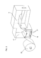
- Fig. 2 shows this second second area 17 in greater detail, where a reel 23 can also be seen, which carries web 3 of flexible sheet material to the machine.
- Figs. 3a and 3b show a comparison between the alternative of using a first submersion tank 19 or using a first decontamination compartment 25 with first spraying means 27.
- Other means are possible for applying to web 3 the liquid that is chemically active as a decontaminating agent, such as for example using a liquid curtain.
- any application method is suitable for the general concept of the invention.
- Preferably inside chamber 15 extends between second treatment area 17 and first treatment area 7. So, recently disinfected web 3 is not in contact at any time with the atmosphere or, generally, with a non-decontaminated environment.
- the liquid bath proper can be used as an airtight barrier between inside chamber 15 and the outside.
- a divider that extends from the inner top part of second area 17 and has its bottom end immersed in the decontaminating liquid, it is possible to insulate inside chamber 15 and the part of second area 17 adjacent thereto with respect to the part of second area 17 adjacent to feeding area 1, and, therefore, with respect to the outside.
- first area 7 it is no longer necessary to inject the first gas inside each preformed packaging (as normally occurs in the state of the art machines), as instead it suffices that the first gas is injected inside first area 7 in a general manner.
- the machine has a plurality of access points 29, needed to access inside the machine to correct any incidents, machine stoppages, or maintenance tasks, etc. These access points 29 are usually distributed along the whole machine, so that all areas of the machine can be accessed.
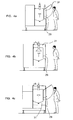
- Figs. 4a, 4b and 4c show some resolution alternatives for access points 29.
- access point 29 has an outside chamber 31 that only extends along the side of the machine.
- outside chamber 31 surrounds the machine both on the side and the top therefore and in Fig. 4c outside chamber 31 surrounds the machine on the side, top and bottom thereof.
- Figs. 5 and 6 show two alternative embodiments of the third chemical decontamination treatment area 13 for the stoppers.
- Fig. 5 shows how the stoppers are suitably selected and orientated by means of vibrating bowls 33 and then introduced into a second decontamination compartment 35 which houses second spraying means that apply to the stoppers, via spraying, a second liquid that is chemically active as a decontaminating agent, normally an aqueous solution of hydrogen peroxide.
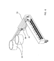
- Fig. 6 shows how the stoppers are introduced into a second submersion tank 39 that contains the second decontaminating liquid.
- the second guiding means 41 are a U-shaped guide that provides for introducing the stoppers and removing them from the second tank 39.
- the stopper aeration step where the latter are dried before being assembled onto the packagings. Both in the case of application through spraying or submersion, it is advantageous that the access points to this part of the machine have an outside chamber.
- a third chemical decontamination treatment area 13 is used for the stoppers, comprising a second submersion tank 39 the decontaminating liquid can be used as an air-tight barrier between the outside and the inside of the machine.
- a submersion tank or using sprayers are non-exclusive alternatives, and they can also be combined together.
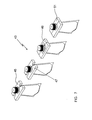
- Stopper attachment area 43 comprises a first stopper prewelding area 45 where the stopper is preattached to the packaging, a second stopper welding area 47 where the stopper is definitively attached to the packaging, and a third stage 49 for welding the sheet material arranged on the stopper sides to the packaging.
- This sheet material has been preheated during the stopper prewelding and welding stages, and therefore it is strongly welded in one stage.
- fourth unit cooling stage 51 which is a conventional cooling stage.
- Fig. 8 shows a diagrammatic view of an example of an outside chamber 31, shaped as a frame with two joints 53, arranged around one access point 29 to inside chamber 15.
Landscapes
- Engineering & Computer Science (AREA)
- Mechanical Engineering (AREA)
- Apparatus For Disinfection Or Sterilisation (AREA)
- Containers And Plastic Fillers For Packaging (AREA)
Abstract
Description
- The invention relates to a machine for horizontally manufacturing flexible sheet material packagings, comprising
- an area for feeding a continuous web of flexible sheet material,
- a preforming area including an area for folding the packaging and a welding area,
- an area for filling the packaging,
- an area for outputting the packagings, and
- a first chemical decontamination treatment area using a first gas that is chemically active as a decontaminating agent, where the first treatment area is arranged between the preforming area and the filling area.
- Various machines of the type indicated above are known. So, for example, document
WO 2005/120960, published on 22 December 2005 , describes a machine of this type. For its part, documentEP 1.743.839, published 17 January 2007 , describes a machine that uses a gas to decontaminate the flexible sheet material before it is preformed. Other similar machines are described in documentsEP 1.245.493, published 2 October 2002 ,ES 2.068.463, published 13 May 2002 ES 2.255.815, published 1 July 2006 ES 2.127.939, published 29 May 1996 - Nevertheless, there is a constant demand to increase the useful life of packaged goods, so that they can be stored for a longer time. This requires increasing the quality of the decontamination and/or reducing the risk of possible contamination after packaging.
- Also, handling the decontamination gas is a complicated process as usually gases that are more or less toxic or irritant to the human body are used, and therefore there is also a permanent interest in improving and facilitating the handling of the decontaminating gas and increasing the safety of the machine operators.
- The aim of the invention is to overcome these drawbacks. This aim is achieved by means of a machine of the type indicated at the beginning, characterised in that it comprises, in addition, an outside chamber that surrounds the machine at least partially and which is depressed with respect to the first area.
- In fact, these machines normally have at least one point for accessing the inside thereof. These access points are necessary for several reasons, such as for example for maintenance tasks, to solve machine stoppages for any unforeseen reason, etc. The access points have a door or openable cover and a fitting frame where a normally airtight closure is established between the cover and the machine structure. These access points always represent a risk of possible sources of contamination, both in the form of bacteria from the outside inwards, and decontaminating agents from the inside outwards, which is a consequent risk for the machine operator. In this respect, it is advantageous that the machine comprises an outside chamber that surrounds the machine at least partially and which is depressed with respect to the first area. In fact, this way it is possible to create an additional barrier between the inside of the machine and the atmosphere. Also, the main function of this outside chamber is to prevent the decontamination gases from possibly leaking out into the atmosphere. Under these conditions, any possible leakage of decontaminating gas is collected in the outside chamber where it can be extracted by a corresponding pump or fan. Preferably the outside chamber is also depressed with respect to atmospheric pressure. This guarantees that there will be no leakage from the outside chamber to the outside. Preferably the depression of the outside chamber with respect to the atmosphere is between 0 and 1000 Pa, and very preferably between 10 and 500 Pa.
- It must be understood that by stating that the outside chamber surrounds the machine at least partially, it is meant that it surrounds at least one part of the machine comprising the fitting frame of an access point. In this respect, it must be taken into account that the outside chamber can only surround the fitting frame of one access point (or even only one part of the fitting frame), can surround the whole access point (both the fitting frame and the cover or door), or it can even surround larger parts of the machine, for example including several access points in one single outside chamber.
- As can be seen, the basic function of the outside chamber is to avoid leakage problems with the access points. In this respect the outside chamber can have various different geometrical shapes. In particular, the outside chamber can completely surround all the various access points on the machine (one single outside chamber for all the access points) or it can only surround some of them. In this latter case it may be that there are other access points which, for whatever reason, do not need an outside chamber or it may be that the machine has a plurality of second chambers, to the extent that the machine could be fitted with second chambers consisting merely of double joint frames arranged around some and/or each access point or the fitting frames proper.
- Advantageously the machine has all its access points arranged on one and the same side and the outside chamber surrounds the machine only on this side. Effectively, grouping the access points in this way simplifies the geometrical shape of the outside chamber.
- Preferably the machine comprises, in addition:
- a second chemical decontamination treatment area where the second treatment area is arranged before the preforming area,
- an inside chamber that extends between the second treatment area and the first treatment area, with the inside chamber being full of a second decontaminating gas, where the second gas in the inside chamber is over pressurised with respect to atmospheric pressure, and preferably, where the outside chamber is also depressed with respect to the inside chamber.
- Effectively, this way the decontamination carried out in the second area is maintained in optimum conditions, and the risk of a new contamination occurring when the sheet web moves through the preforming area is avoided. Also, since the second gas in the inside chamber is over pressurised with respect to atmospheric pressure it is guaranteed that, even if there is a leak or hole in the machine, atmospheric air will never enter the inside chamber. This way the inside chamber is an insulator with over pressurised decontaminating gas.
- Furthermore, since the outside chamber is also depressed with respect to the inside chamber, leakages of the second decontaminating gas outwards are also avoided.
- This way, another possible reason for having two second chambers could be if the first decontaminating gas and the second decontaminating gas were different from one another. Then there could be an outside chamber surrounding the access points in the first area (and, possibly, the filling and output areas) and another outside chamber surrounding the access points in the inside chamber (which will usually comprise the preforming area), since it may be convenient to treat the possible leakages of the first gas and the second gas in a different way.
- Nevertheless, it must be noted that the outside chamber is advantageous both if the inside chamber contains a decontaminating gas or not because, at any event, the first area will always contain the first decontaminating gas.
- Advantageously the second chemical decontaminating treatment area consists in applying a chemically active decontaminating liquid to the sheet web. Effectively, using a chemically active liquid guarantees that the whole sheet web is treated. Also, using a liquid guarantees that a greater concentration of the decontaminating agent reaches each point of the sheet web. Applying the chemically active liquid to the sheet web before the preforming area means that it is applied to the sheet web when the latter is still completely unwound. Under these conditions, the liquid can reach all the points of the web much more easily than if the web were folded, when corners and angles are formed that are difficult to access. Moreover, it is also easier to remove the liquid once the decontamination has taken place. It must be taken into consideration that using a liquid has the additional advantage that the liquid cleans by mechanically dragging all kinds of dirt, dust, etc. that may be on the web, and this is impossible, or almost impossible to achieve with a gas, considering the flow rates and pressures conventionally used in this type of machines. Another additional advantage is that the liquid can reach and, therefore, disinfect, small scratches that may appear on the web, and which a gas current could not reach.
- A preferable embodiment of the invention is obtained when the second area comprises a first submersion tank containing the liquid and first guiding means that introduce the web into the tank so that the liquid is applied by immersing the web in said liquid.
- Alternatively, the second area comprises a first decontaminating compartment which houses first spraying means and first guiding means that introduce the web into the first compartment so that the liquid is applied by spraying the liquid on to said web. This application could be performed on only one of the web surfaces, specifically on the inner surface, which is the one that will have difficult to access corners and angles when the web is folded. Nevertheless, preferably the liquid is applied to both web surfaces.
- At any event, both solutions have the advantage that they do not affect the machine's productivity, as the areas can be made longer or shorter depending on the desired contact time with the decontaminating agent without affecting the machine cycle time.
- In addition, it is particularly advantageous that the first gas in the first area is over pressurised with respect to the pressure in the inside chamber, as this way a flow is established extending from the first area to the inside chamber. It must be taken into account that the first area is just before the packaging filling area, where maximum septic conditions must be observed. Generally, it is particularly advantageous that the first area be over pressurised with respect to atmospheric pressure as this minimises the risk of contamination through contaminated air entering the first area, either through possible access points or through any other point that may have a hole or porosity connected directly or indirectly with the atmosphere. Preferably the overpressure in the first area with respect to atmospheric pressure is between 5 and 500 Pa, and very preferably between 10 and 100 Pa.
- Both the first gas and the second gas must be chemically active as decontaminating agents. This can be achieved in various ways, all compatible with this invention. In practice, the most usual is that these gases consist of a mixture of various components, where at least one of them is the real decontaminating agent, and the other components are essentially responsible for acting as a vehicle for transporting the active components. Advantageously, the first gas and/or the second gas comprise H2O2 (hydrogen peroxide) in a gaseous state as the decontaminating agent.
- Also, the liquid must be chemically active as a decontaminating agent, which can also be obtained in various ways, all compatible with this invention. Also in the case of the liquid, it is often a mixture of components, where at least one of them is the real decontaminating agent. As in the case of the gas, it is advantageous that the liquid comprises H2O2 in a liquid state as the decontaminating agent.
- Another advantageous embodiment of the machine according to the invention is obtained when the second chemical decontamination treatment area employs a third gas that is chemically active as a decontaminating agent, which, preferably, comprises H2O2 in a gaseous state. In this case, the whole machine performs the complete web decontaminating process by gaseous means.
- Preferably the decontaminating gases are produced in external equipment, so that the previously produced decontaminating gas is injected into the machine (in the first area and/or in the inside chamber and/or in the second area). This ensures a more uniform distribution than if a decontaminating liquid is sprayed inside the machine to evaporate and be distributed inside the machine. Also, this system provides for regulating the concentration of decontaminating agent in the decontaminating gas, so that in each case the desired concentration is applied uniformly throughout the compartment in question.
- Generally, the decontaminating gas is, inside the corresponding compartment, at a temperature of between 40°C and 70°C, particularly when the decontaminating agent is H2O2. For its part, the decontaminating liquid is preferably at a temperature of between 40°C and 80°C, particularly when the decontaminating agent is H2O2. In this respect, it must be understood that when it is stated that the gases must be chemically active as decontaminating agents, it must be understood that they must be chemically active as microbiological decontaminating agents and within the range of temperatures between 40°C and 70°C. Similarly, it must be understood that the decontaminating liquid is chemically active as a microbiological decontaminating agent within the range of temperatures between 40°C and 80°C. Also it must be clear that both hot air and water vapour are considered to be excluded from this definition of decontaminating gas.
- Usually the packagings have top stoppers. These stoppers are usually assembled onto the packaging once the latter has been filled with the corresponding product. This stage of assembling the stopper onto the packaging is usually performed in the same machine. In this respect it is advantageous that the machine comprises a third chemical decontamination treatment area that applies to said stoppers a second liquid that is chemically active as a decontaminating agent. Effectively, this way the decontaminating (and mechanical cleaning) advantages are also applied via a liquid to the stoppers, which increases the extent of the unit's decontamination.
- As in the case of the second chemical decontamination treatment area, the liquid can be applied by submersion or spraying. Therefore, a preferable solution would consist in the third area comprising a second submersion tank that contains the second liquid and second guiding means that introduce the stoppers into the second tank so that the second liquid is applied through submersion, whereas another preferable solution would consist in the third area comprising a second decontamination compartment which houses second spraying means and second guiding means that introduce the stoppers into the second compartment so that the second liquid is applied by spraying it onto the stoppers. In either of the two cases, preferably the second liquid comprises hydrogen peroxide as the decontaminating agent.
- Advantageously, when the packagings comprise top stoppers, the machine comprises an area for attaching the stoppers to the packaging, where the stopper attachment area, in turn, comprises a first area for prewelding the stopper to the sheet material, a second area for welding the stopper to the sheet material and a third area for welding the sheet material arranged on the sides of the stopper.
- Another known way of decontaminating packagings is via ultraviolet radiation (UV rays) of the sheet material web and/or the packaging in any of its formation stages. Logically, this method of decontamination is completely compatible with this invention, and therefore it is possible to include one or more UV radiation stages in any part of the process, such as for example in the preforming area. Also, the UV radiation step can be added to an area where there is no gas that is chemically active as a decontaminating agent or, on the contrary, it can be added to an area where there is also a decontaminating gas, although in the latter case care should be taken to ensure that the UV rays do not negatively affect the decontaminating properties of the gas.
- Other advantages and characteristics of the invention will be appreciated from the following description, which provides a non-limiting description of some preferable embodiments of the invention, with reference to the accompanying drawings, in which:
-
Fig. 1 , a diagrammatical front view, of a longitudinal section of a machine according to the invention. -
Fig. 2 , a diagrammatical perspective view, of a longitudinal section of a second chemical decontamination treatment area according to the invention. -
Figs. 3a and 3b , diagrammatical front views, of a second submersion (Fig. 3a ) and spray (Fig. 3b ) treatment area. -
Figs. 4a, 4b and 4c , side views of cross-sections of the machine inFig. 1 showing three possible alternative geometrical shapes of the second outside chambers. -
Fig. 5 , a perspective view, partially sectioned of a third chemical decontamination treatment area of the stoppers via spraying. -
Fig. 6 , a perspective view, partially sectioned of a third chemical decontamination treatment area of the stoppers through submersion. -
Fig. 7 , a perspective view of the sequence followed in a stopper attachment area according to the invention. -
Fig. 8 , a diagrammatic view of an outside chamber shaped with a double joint frame. -
Fig. 1 shows a machine for horizontally manufacturing flexible sheet material packagings according to the invention. The machine has an area 1 for feeding a continuoussheet material web 3. Thisweb 3 is preformed in apreforming area 5 where it is folded so as to form the bottom wall of the packaging and the sides of the packaging are welded, after whichweb 3 is cut so that the packagings are separated from each other. Then the packagings enter a first chemical decontamination area 7 by means of a first gas that is chemically active as a decontaminating agent, in particularly a gas containing hydrogen peroxide. Once the packagings are decontaminated, they are filled in the filling area 9, the stopper is added and they are removed through theoutput area 11. The stopper, in turn, passes through athird chemical decontamination 13 treatment area. - First area 7 is full of the first gas and is over pressurised with respect to the atmosphere. Between first area 7 and filling area 9 there are closing means (a semi-closed wall) which, together with a suitable pressure difference, prevent the first gas from passing into filling area 9 (although air can pass from filling area 9 to first area 7). Filling area 9 is the most sterile area in the whole of the machine, but it can no longer contain gases that may be hazardous to health, and therefore it is full of sterile air.
Output area 11 has other closing means that prevent atmospheric air from entering. Between the preformingarea 5 and first area 7 there is a narrow passage.Preforming area 5 is also over pressurised with respect to the atmosphere, but its pressure is lower than first area 7, so that a gas current flow is established extending from first area 7 to preformingarea 5. Thisway preforming area 5 defines aninside chamber 15 that extends throughout the preforming area. In this case, the second decontaminating gas is the same as the first decontaminating gas. - Between feeding area 1 and preforming
area 5 there is a second chemicaldecontamination treatment area 17, whereweb 3 is immersed in afirst submersion tank 19 containing a decontaminating liquid that has hydrogen peroxide. First guiding means 21, consisting of some rollers, guideweb 3 throughfirst tank 19.Fig. 2 shows this secondsecond area 17 in greater detail, where areel 23 can also be seen, which carriesweb 3 of flexible sheet material to the machine.Figs. 3a and 3b show a comparison between the alternative of using afirst submersion tank 19 or using afirst decontamination compartment 25 with first spraying means 27. Other means are possible for applying toweb 3 the liquid that is chemically active as a decontaminating agent, such as for example using a liquid curtain. Generally any application method is suitable for the general concept of the invention. Preferably insidechamber 15 extends betweensecond treatment area 17 and first treatment area 7. So, recently disinfectedweb 3 is not in contact at any time with the atmosphere or, generally, with a non-decontaminated environment. - Additionally, by using a
first tank 19 the liquid bath proper can be used as an airtight barrier betweeninside chamber 15 and the outside. Effectively, by adding a divider that extends from the inner top part ofsecond area 17 and has its bottom end immersed in the decontaminating liquid, it is possible to insulate insidechamber 15 and the part ofsecond area 17 adjacent thereto with respect to the part ofsecond area 17 adjacent to feeding area 1, and, therefore, with respect to the outside. - With this embodiment, once
web 3 has enteredsecond area 17, at no time does it leave a sterile atmosphere, as the whole of the inside of the machine is in a decontaminated or sterile atmosphere. Consequently, in first area 7 it is no longer necessary to inject the first gas inside each preformed packaging (as normally occurs in the state of the art machines), as instead it suffices that the first gas is injected inside first area 7 in a general manner. - The machine has a plurality of
access points 29, needed to access inside the machine to correct any incidents, machine stoppages, or maintenance tasks, etc. These access points 29 are usually distributed along the whole machine, so that all areas of the machine can be accessed.Figs. 4a, 4b and 4c show some resolution alternatives for access points 29. InFig. 4a access point 29 has anoutside chamber 31 that only extends along the side of the machine. InFig. 4b , outsidechamber 31 surrounds the machine both on the side and the top therefore and inFig. 4c outsidechamber 31 surrounds the machine on the side, top and bottom thereof. -
Figs. 5 and6 show two alternative embodiments of the third chemicaldecontamination treatment area 13 for the stoppers.Fig. 5 shows how the stoppers are suitably selected and orientated by means of vibratingbowls 33 and then introduced into asecond decontamination compartment 35 which houses second spraying means that apply to the stoppers, via spraying, a second liquid that is chemically active as a decontaminating agent, normally an aqueous solution of hydrogen peroxide. For its part,Fig. 6 shows how the stoppers are introduced into asecond submersion tank 39 that contains the second decontaminating liquid. In this case, the second guiding means 41 are a U-shaped guide that provides for introducing the stoppers and removing them from thesecond tank 39. Following the submersion, there is a stopper aeration step, where the latter are dried before being assembled onto the packagings. Both in the case of application through spraying or submersion, it is advantageous that the access points to this part of the machine have an outside chamber. - As in the case of second
chemical decontamination area 17, if a third chemicaldecontamination treatment area 13 is used for the stoppers, comprising asecond submersion tank 39 the decontaminating liquid can be used as an air-tight barrier between the outside and the inside of the machine. Generally, it must be considered that, both insecond area 17 and inthird area 13 using a submersion tank or using sprayers are non-exclusive alternatives, and they can also be combined together. -
Fig. 7 shows in detail the stages of attaching the stoppers to the packagings.Stopper attachment area 43 comprises a firststopper prewelding area 45 where the stopper is preattached to the packaging, a secondstopper welding area 47 where the stopper is definitively attached to the packaging, and athird stage 49 for welding the sheet material arranged on the stopper sides to the packaging. This sheet material has been preheated during the stopper prewelding and welding stages, and therefore it is strongly welded in one stage. Finally, there is a fourthunit cooling stage 51, which is a conventional cooling stage. -
Fig. 8 shows a diagrammatic view of an example of anoutside chamber 31, shaped as a frame with twojoints 53, arranged around oneaccess point 29 toinside chamber 15.
Claims (14)
- - Machine for horizontally manufacturing flexible sheet material packagings, comprising- an area for feeding (1) a continuous web (3) of flexible sheet material,- a preforming area (5) including an area for folding the bottom wall of said packaging and a welding area,- an area for filling (9) said packagings,- an area for outputting (11) said packagings,- a first chemical decontamination treatment area (7) using a first gas that is chemically active as a decontaminating agent, where said first treatment area (7) is arranged between the preforming area (5) and the filling area (9).characterized in that it comprises, in addition, an outside chamber (31) that surrounds said machine at least partially and is depressed with respect to said first area (7).
- - Machine according to claim1, characterized in that said outside chamber (31) is also depressed with respect to atmospheric pressure, with said depression of said outside chamber (31) with respect to the atmosphere being preferably between 0 and 1000 Pa, and very preferably between 10 and 500 Pa.
- - Machine according to one of claims 1 or 2, characterized in that it comprises, in addition,- a second chemical decontamination treatment area (17) where said second treatment area (17) is arranged before the preforming area (5),- an inside chamber (15) that extends between said second treatment area (17) and first treatment area (7), where inside chamber (15) is full of a second decontaminating gas, where said second gas in said inside chamber (15) is over pressurised with respect to atmospheric pressure, where said outside chamber is also depressed with respect to the inside chamber.
- - Machine according to claim 3, characterized in that said second chemical decontamination treatment area (17) consists in applying to said sheet web (3) a liquid that is chemically active as a decontaminating agent.
- - Machine according to claim 4, characterized in that said second area (17) comprises a submersion tank (19) containing said liquid and guiding means (21) that introduce said web (3) into said first tank (19) so that said liquid is applied by immersing said web (3) in said liquid.
- - Machine according to claim 4, characterized in that said second area (17) comprises a first decontamination compartment (25) which houses first spraying means (27) and first guiding means (21) that introduce said web (3) into said first compartment (25) so that said liquid is applied by spraying said liquid onto said web (3).
- - Machine according to any of the claims 3 to 6, characterized in that said first gas in said first area (7) is over pressurised with respect to the pressure in said inside chamber (15).
- - Machine according to any of the claims 1 to 7, where said first area (7) is over pressurised with respect to atmospheric pressure, characterized in that said overpressure in said first area (7) with respect to atmospheric pressure is between 5 and 500 Pa, and preferably between 10 and 100 Pa.
- - Machine according to any of the claims 3 to 8, characterized in that said second chemical decontamination treatment area (17) is by means of a third gas that is chemically active as a decontaminating agent.
- - Machine according to any of the claims 1 to 9, which has a plurality of access points (29), characterized in that it has all the access points (29) thereto on one and the same side and said outside chamber (31) surrounds said machine only on said side.
- - Machine according to any of the claims 1 to 10, where said packagings comprise top stoppers, characterized in that it comprises a third chemical decontamination treatment area (13) consisting in applying to said stoppers a second liquid that is chemically active as a decontaminating agent.
- - Machine according to claim 11, characterized in that said third area (13) comprises a second submersion tank (39) containing said second liquid and second guiding means (41) that introduce said stoppers into said second tank (39) so that said second liquid is applied by submersion.
- - Machine according to claim 11, characterized in that said third area (13) comprises a second decontamination compartment (35) which houses second spraying means and second guiding means (41) that introduce said stoppers into said second compartment (35) so that said second liquid is applied by spraying said second liquid onto said stoppers.
- - Machine according to any of the claims 1 to 13, wherein said packagings comprise top stoppers, characterized in that it comprises an area (43) for attaching said stoppers to said packagings, wherein said stopper attachment area (43), in turn, comprises a first area (45) for prewelding the stopper to the sheet material, a second area (47) for welding the stopper to the sheet material and a third area (49) for welding the sheet material arranged on the sides of the stopper.
Applications Claiming Priority (2)
| Application Number | Priority Date | Filing Date | Title |
|---|---|---|---|
| ES200702243U ES1066615Y (en) | 2007-11-05 | 2007-11-05 | MACHINE FOR HORIZONTAL MANUFACTURE OF FLEXIBLE LAMINAR MATERIAL PACKAGING |
| ES200702242U ES1066614Y (en) | 2007-11-05 | 2007-11-05 | MACHINE FOR HORIZONTAL MANUFACTURE OF FLEXIBLE LAMINAR MATERIAL PACKAGING WITH DECONTAMINATION BY LIQUID AND GASEOUS VIA |
Publications (3)
| Publication Number | Publication Date |
|---|---|
| EP2055638A2 true EP2055638A2 (en) | 2009-05-06 |
| EP2055638A3 EP2055638A3 (en) | 2011-05-11 |
| EP2055638B1 EP2055638B1 (en) | 2012-06-06 |
Family
ID=40362915
Family Applications (1)
| Application Number | Title | Priority Date | Filing Date |
|---|---|---|---|
| EP08380311A Not-in-force EP2055638B1 (en) | 2007-11-05 | 2008-11-04 | Machine with outside chamber for horizontally manufacturing flexible sheet material packagings |
Country Status (2)
| Country | Link |
|---|---|
| EP (1) | EP2055638B1 (en) |
| ES (1) | ES2388011T3 (en) |
Cited By (2)
| Publication number | Priority date | Publication date | Assignee | Title |
|---|---|---|---|---|
| WO2010058186A3 (en) * | 2008-11-21 | 2010-10-14 | Elopak Systems Ag | Improvements in or relating to sealing |
| EP2631195A1 (en) | 2012-02-23 | 2013-08-28 | Cryovac, Inc. | Pouch and method of manufacturing the same |
Family Cites Families (3)
| Publication number | Priority date | Publication date | Assignee | Title |
|---|---|---|---|---|
| IT1201997B (en) * | 1985-11-11 | 1989-02-02 | Consiglio Nazionale Ricerche | PROCEDURE FOR SANITIZING CONTAINERS AND PACKAGING MATERIALS, PARTICULARLY FOR PHARMACEUTICAL AND COSMETIC USE, AND PLANT FOR PERFORMING THE PROCEDURE |
| ES2255815B1 (en) * | 2004-06-10 | 2007-08-01 | Volpak, S.A. | DEVICE AND PROCEDURE FOR THE CONFORMATION, FILLING AND SEALING OF FLEXIBLE AND FLACIDATED LAMINAR MATERIAL PACKAGING. |
| EP1743839A1 (en) * | 2005-07-14 | 2007-01-17 | Aseptis, S.L. | A horizontal packaging machine with film sterilization and method for forming packages from a film |
-
2008
- 2008-11-04 ES ES08380311T patent/ES2388011T3/en active Active
- 2008-11-04 EP EP08380311A patent/EP2055638B1/en not_active Not-in-force
Cited By (3)
| Publication number | Priority date | Publication date | Assignee | Title |
|---|---|---|---|---|
| WO2010058186A3 (en) * | 2008-11-21 | 2010-10-14 | Elopak Systems Ag | Improvements in or relating to sealing |
| EP2631195A1 (en) | 2012-02-23 | 2013-08-28 | Cryovac, Inc. | Pouch and method of manufacturing the same |
| WO2013124201A1 (en) | 2012-02-23 | 2013-08-29 | Cryovac, Inc. | Pouch and method of manufacturing the same |
Also Published As
| Publication number | Publication date |
|---|---|
| ES2388011T3 (en) | 2012-10-05 |
| EP2055638A3 (en) | 2011-05-11 |
| EP2055638B1 (en) | 2012-06-06 |
Similar Documents
| Publication | Publication Date | Title |
|---|---|---|
| JP4263625B2 (en) | Packaging containers for aseptic or sterilized objects | |
| JP4373910B2 (en) | Packaging containers for the transport of sterile objects or objects to be disinfected | |
| JP4924570B2 (en) | Isolator system | |
| JP3424943B2 (en) | Method and apparatus for sterilizing a continuous packaging material web | |
| US20100224224A1 (en) | Washer and decontaminator with lid control | |
| JPH11277005A (en) | Non-blocking circulation processing equipment for perforating equipment | |
| KR920010795B1 (en) | Apparatus for sterilizing moving webs | |
| JPH11276559A (en) | Integrated cleaning / sterilization method for perforator | |
| KR20180134352A (en) | DEACTIVATION WIPE KIT AND METHOD FOR FORMING AND USING THE SAME | |
| US20080236621A1 (en) | Integrated washer and sterilizer | |
| CA1296985C (en) | Apparatus for sterilizing film and like packaging material | |
| US20230001623A1 (en) | Method and installation for manufacturing and treating sterile plastic containers | |
| EP2055638B1 (en) | Machine with outside chamber for horizontally manufacturing flexible sheet material packagings | |
| KR20210058831A (en) | POUCH WITH BREAKABLE SEAL | |
| ITBO20080626A1 (en) | METHOD FOR TRAINING AND FILLING CONTAINERS FOR FOOD USE | |
| US10053251B2 (en) | Method for sterilizing packaging | |
| US8176711B2 (en) | Machine for horizontally manufacturing flexible sheet material packagings with outside chamber | |
| US20230056171A1 (en) | Sterilizing device and method for sterilizing an outer face of a receptacle | |
| JP6249713B2 (en) | Electron beam sterilizer and sterilization method inside sterilization container using the same | |
| JP2002205714A (en) | Aseptic filling device | |
| CN113797364B (en) | Shielding structure | |
| RU2546479C2 (en) | Filling machine with sealing valve | |
| CA3164393C (en) | Sterilizing device and method for sterilizing an outer face of a receptacle | |
| DE202025100413U1 (en) | Bottling plant for beverages | |
| JP2025521464A (en) | Method for the manipulation of sterilized objects in a controlled atmosphere chamber, corresponding device, corresponding object, and corresponding machine |
Legal Events
| Date | Code | Title | Description |
|---|---|---|---|
| PUAI | Public reference made under article 153(3) epc to a published international application that has entered the european phase |
Free format text: ORIGINAL CODE: 0009012 |
|
| AK | Designated contracting states |
Kind code of ref document: A2 Designated state(s): AT BE BG CH CY CZ DE DK EE ES FI FR GB GR HR HU IE IS IT LI LT LU LV MC MT NL NO PL PT RO SE SI SK TR |
|
| AX | Request for extension of the european patent |
Extension state: AL BA MK RS |
|
| PUAL | Search report despatched |
Free format text: ORIGINAL CODE: 0009013 |
|
| AK | Designated contracting states |
Kind code of ref document: A3 Designated state(s): AT BE BG CH CY CZ DE DK EE ES FI FR GB GR HR HU IE IS IT LI LT LU LV MC MT NL NO PL PT RO SE SI SK TR |
|
| AX | Request for extension of the european patent |
Extension state: AL BA MK RS |
|
| RIC1 | Information provided on ipc code assigned before grant |
Ipc: B65B 9/08 20060101AFI20090312BHEP Ipc: B65B 59/00 20060101ALI20110407BHEP Ipc: B65B 61/18 20060101ALI20110407BHEP Ipc: B65B 55/02 20060101ALI20110407BHEP Ipc: B65B 55/10 20060101ALI20110407BHEP |
|
| 17P | Request for examination filed |
Effective date: 20111108 |
|
| GRAP | Despatch of communication of intention to grant a patent |
Free format text: ORIGINAL CODE: EPIDOSNIGR1 |
|
| AKX | Designation fees paid |
Designated state(s): AT BE BG CH CY CZ DE DK EE ES FI FR GB GR HR HU IE IS IT LI LT LU LV MC MT NL NO PL PT RO SE SI SK TR |
|
| RIC1 | Information provided on ipc code assigned before grant |
Ipc: B65B 55/02 20060101ALI20111212BHEP Ipc: B65B 55/10 20060101ALI20111212BHEP Ipc: B65B 9/08 20120101AFI20111212BHEP Ipc: B65B 61/18 20060101ALI20111212BHEP Ipc: B65B 59/00 20060101ALI20111212BHEP |
|
| GRAS | Grant fee paid |
Free format text: ORIGINAL CODE: EPIDOSNIGR3 |
|
| GRAA | (expected) grant |
Free format text: ORIGINAL CODE: 0009210 |
|
| AK | Designated contracting states |
Kind code of ref document: B1 Designated state(s): AT BE BG CH CY CZ DE DK EE ES FI FR GB GR HR HU IE IS IT LI LT LU LV MC MT NL NO PL PT RO SE SI SK TR |
|
| REG | Reference to a national code |
Ref country code: GB Ref legal event code: FG4D |
|
| REG | Reference to a national code |
Ref country code: AT Ref legal event code: REF Ref document number: 560897 Country of ref document: AT Kind code of ref document: T Effective date: 20120615 Ref country code: CH Ref legal event code: EP |
|
| REG | Reference to a national code |
Ref country code: CH Ref legal event code: NV Representative=s name: MICHELI & CIE SA |
|
| REG | Reference to a national code |
Ref country code: IE Ref legal event code: FG4D |
|
| REG | Reference to a national code |
Ref country code: SE Ref legal event code: TRGR |
|
| REG | Reference to a national code |
Ref country code: DE Ref legal event code: R096 Ref document number: 602008016164 Country of ref document: DE Effective date: 20120802 |
|
| REG | Reference to a national code |
Ref country code: NL Ref legal event code: T3 |
|
| REG | Reference to a national code |
Ref country code: ES Ref legal event code: FG2A Ref document number: 2388011 Country of ref document: ES Kind code of ref document: T3 Effective date: 20121005 |
|
| PG25 | Lapsed in a contracting state [announced via postgrant information from national office to epo] |
Ref country code: CY Free format text: LAPSE BECAUSE OF FAILURE TO SUBMIT A TRANSLATION OF THE DESCRIPTION OR TO PAY THE FEE WITHIN THE PRESCRIBED TIME-LIMIT Effective date: 20120606 Ref country code: FI Free format text: LAPSE BECAUSE OF FAILURE TO SUBMIT A TRANSLATION OF THE DESCRIPTION OR TO PAY THE FEE WITHIN THE PRESCRIBED TIME-LIMIT Effective date: 20120606 Ref country code: NO Free format text: LAPSE BECAUSE OF FAILURE TO SUBMIT A TRANSLATION OF THE DESCRIPTION OR TO PAY THE FEE WITHIN THE PRESCRIBED TIME-LIMIT Effective date: 20120906 Ref country code: LT Free format text: LAPSE BECAUSE OF FAILURE TO SUBMIT A TRANSLATION OF THE DESCRIPTION OR TO PAY THE FEE WITHIN THE PRESCRIBED TIME-LIMIT Effective date: 20120606 |
|
| REG | Reference to a national code |
Ref country code: AT Ref legal event code: MK05 Ref document number: 560897 Country of ref document: AT Kind code of ref document: T Effective date: 20120606 |
|
| REG | Reference to a national code |
Ref country code: LT Ref legal event code: MG4D Effective date: 20120606 |
|
| PG25 | Lapsed in a contracting state [announced via postgrant information from national office to epo] |
Ref country code: SI Free format text: LAPSE BECAUSE OF FAILURE TO SUBMIT A TRANSLATION OF THE DESCRIPTION OR TO PAY THE FEE WITHIN THE PRESCRIBED TIME-LIMIT Effective date: 20120606 Ref country code: HR Free format text: LAPSE BECAUSE OF FAILURE TO SUBMIT A TRANSLATION OF THE DESCRIPTION OR TO PAY THE FEE WITHIN THE PRESCRIBED TIME-LIMIT Effective date: 20120606 Ref country code: LV Free format text: LAPSE BECAUSE OF FAILURE TO SUBMIT A TRANSLATION OF THE DESCRIPTION OR TO PAY THE FEE WITHIN THE PRESCRIBED TIME-LIMIT Effective date: 20120606 Ref country code: GR Free format text: LAPSE BECAUSE OF FAILURE TO SUBMIT A TRANSLATION OF THE DESCRIPTION OR TO PAY THE FEE WITHIN THE PRESCRIBED TIME-LIMIT Effective date: 20120907 |
|
| PG25 | Lapsed in a contracting state [announced via postgrant information from national office to epo] |
Ref country code: SK Free format text: LAPSE BECAUSE OF FAILURE TO SUBMIT A TRANSLATION OF THE DESCRIPTION OR TO PAY THE FEE WITHIN THE PRESCRIBED TIME-LIMIT Effective date: 20120606 Ref country code: RO Free format text: LAPSE BECAUSE OF FAILURE TO SUBMIT A TRANSLATION OF THE DESCRIPTION OR TO PAY THE FEE WITHIN THE PRESCRIBED TIME-LIMIT Effective date: 20120606 Ref country code: AT Free format text: LAPSE BECAUSE OF FAILURE TO SUBMIT A TRANSLATION OF THE DESCRIPTION OR TO PAY THE FEE WITHIN THE PRESCRIBED TIME-LIMIT Effective date: 20120606 Ref country code: BE Free format text: LAPSE BECAUSE OF FAILURE TO SUBMIT A TRANSLATION OF THE DESCRIPTION OR TO PAY THE FEE WITHIN THE PRESCRIBED TIME-LIMIT Effective date: 20120606 Ref country code: CZ Free format text: LAPSE BECAUSE OF FAILURE TO SUBMIT A TRANSLATION OF THE DESCRIPTION OR TO PAY THE FEE WITHIN THE PRESCRIBED TIME-LIMIT Effective date: 20120606 Ref country code: IS Free format text: LAPSE BECAUSE OF FAILURE TO SUBMIT A TRANSLATION OF THE DESCRIPTION OR TO PAY THE FEE WITHIN THE PRESCRIBED TIME-LIMIT Effective date: 20121006 Ref country code: EE Free format text: LAPSE BECAUSE OF FAILURE TO SUBMIT A TRANSLATION OF THE DESCRIPTION OR TO PAY THE FEE WITHIN THE PRESCRIBED TIME-LIMIT Effective date: 20120606 |
|
| PG25 | Lapsed in a contracting state [announced via postgrant information from national office to epo] |
Ref country code: PL Free format text: LAPSE BECAUSE OF FAILURE TO SUBMIT A TRANSLATION OF THE DESCRIPTION OR TO PAY THE FEE WITHIN THE PRESCRIBED TIME-LIMIT Effective date: 20120606 Ref country code: PT Free format text: LAPSE BECAUSE OF FAILURE TO SUBMIT A TRANSLATION OF THE DESCRIPTION OR TO PAY THE FEE WITHIN THE PRESCRIBED TIME-LIMIT Effective date: 20121008 |
|
| PLBE | No opposition filed within time limit |
Free format text: ORIGINAL CODE: 0009261 |
|
| STAA | Information on the status of an ep patent application or granted ep patent |
Free format text: STATUS: NO OPPOSITION FILED WITHIN TIME LIMIT |
|
| PG25 | Lapsed in a contracting state [announced via postgrant information from national office to epo] |
Ref country code: DK Free format text: LAPSE BECAUSE OF FAILURE TO SUBMIT A TRANSLATION OF THE DESCRIPTION OR TO PAY THE FEE WITHIN THE PRESCRIBED TIME-LIMIT Effective date: 20120606 |
|
| 26N | No opposition filed |
Effective date: 20130307 |
|
| REG | Reference to a national code |
Ref country code: DE Ref legal event code: R097 Ref document number: 602008016164 Country of ref document: DE Effective date: 20130307 |
|
| PG25 | Lapsed in a contracting state [announced via postgrant information from national office to epo] |
Ref country code: BG Free format text: LAPSE BECAUSE OF FAILURE TO SUBMIT A TRANSLATION OF THE DESCRIPTION OR TO PAY THE FEE WITHIN THE PRESCRIBED TIME-LIMIT Effective date: 20120906 |
|
| REG | Reference to a national code |
Ref country code: IE Ref legal event code: MM4A |
|
| PG25 | Lapsed in a contracting state [announced via postgrant information from national office to epo] |
Ref country code: IE Free format text: LAPSE BECAUSE OF NON-PAYMENT OF DUE FEES Effective date: 20121104 |
|
| PG25 | Lapsed in a contracting state [announced via postgrant information from national office to epo] |
Ref country code: MT Free format text: LAPSE BECAUSE OF FAILURE TO SUBMIT A TRANSLATION OF THE DESCRIPTION OR TO PAY THE FEE WITHIN THE PRESCRIBED TIME-LIMIT Effective date: 20120606 |
|
| PG25 | Lapsed in a contracting state [announced via postgrant information from national office to epo] |
Ref country code: TR Free format text: LAPSE BECAUSE OF FAILURE TO SUBMIT A TRANSLATION OF THE DESCRIPTION OR TO PAY THE FEE WITHIN THE PRESCRIBED TIME-LIMIT Effective date: 20120606 Ref country code: MC Free format text: LAPSE BECAUSE OF NON-PAYMENT OF DUE FEES Effective date: 20121130 |
|
| PG25 | Lapsed in a contracting state [announced via postgrant information from national office to epo] |
Ref country code: LU Free format text: LAPSE BECAUSE OF NON-PAYMENT OF DUE FEES Effective date: 20121104 |
|
| PG25 | Lapsed in a contracting state [announced via postgrant information from national office to epo] |
Ref country code: HU Free format text: LAPSE BECAUSE OF FAILURE TO SUBMIT A TRANSLATION OF THE DESCRIPTION OR TO PAY THE FEE WITHIN THE PRESCRIBED TIME-LIMIT Effective date: 20081104 |
|
| REG | Reference to a national code |
Ref country code: FR Ref legal event code: PLFP Year of fee payment: 8 |
|
| REG | Reference to a national code |
Ref country code: FR Ref legal event code: PLFP Year of fee payment: 9 |
|
| REG | Reference to a national code |
Ref country code: FR Ref legal event code: PLFP Year of fee payment: 10 |
|
| REG | Reference to a national code |
Ref country code: FR Ref legal event code: PLFP Year of fee payment: 11 |
|
| PGFP | Annual fee paid to national office [announced via postgrant information from national office to epo] |
Ref country code: NL Payment date: 20191126 Year of fee payment: 12 Ref country code: DE Payment date: 20191129 Year of fee payment: 12 Ref country code: SE Payment date: 20191122 Year of fee payment: 12 |
|
| PGFP | Annual fee paid to national office [announced via postgrant information from national office to epo] |
Ref country code: IT Payment date: 20191125 Year of fee payment: 12 Ref country code: FR Payment date: 20191125 Year of fee payment: 12 |
|
| PGFP | Annual fee paid to national office [announced via postgrant information from national office to epo] |
Ref country code: CH Payment date: 20191121 Year of fee payment: 12 |
|
| PGFP | Annual fee paid to national office [announced via postgrant information from national office to epo] |
Ref country code: GB Payment date: 20191127 Year of fee payment: 12 Ref country code: ES Payment date: 20200228 Year of fee payment: 12 |
|
| REG | Reference to a national code |
Ref country code: DE Ref legal event code: R119 Ref document number: 602008016164 Country of ref document: DE |
|
| REG | Reference to a national code |
Ref country code: SE Ref legal event code: EUG |
|
| REG | Reference to a national code |
Ref country code: CH Ref legal event code: PL |
|
| REG | Reference to a national code |
Ref country code: NL Ref legal event code: MM Effective date: 20201201 |
|
| GBPC | Gb: european patent ceased through non-payment of renewal fee |
Effective date: 20201104 |
|
| PG25 | Lapsed in a contracting state [announced via postgrant information from national office to epo] |
Ref country code: LI Free format text: LAPSE BECAUSE OF NON-PAYMENT OF DUE FEES Effective date: 20201130 Ref country code: SE Free format text: LAPSE BECAUSE OF NON-PAYMENT OF DUE FEES Effective date: 20201105 Ref country code: NL Free format text: LAPSE BECAUSE OF NON-PAYMENT OF DUE FEES Effective date: 20201201 Ref country code: CH Free format text: LAPSE BECAUSE OF NON-PAYMENT OF DUE FEES Effective date: 20201130 |
|
| PG25 | Lapsed in a contracting state [announced via postgrant information from national office to epo] |
Ref country code: IT Free format text: LAPSE BECAUSE OF NON-PAYMENT OF DUE FEES Effective date: 20201104 Ref country code: FR Free format text: LAPSE BECAUSE OF NON-PAYMENT OF DUE FEES Effective date: 20201130 |
|
| PG25 | Lapsed in a contracting state [announced via postgrant information from national office to epo] |
Ref country code: GB Free format text: LAPSE BECAUSE OF NON-PAYMENT OF DUE FEES Effective date: 20201104 Ref country code: DE Free format text: LAPSE BECAUSE OF NON-PAYMENT OF DUE FEES Effective date: 20210601 |
|
| REG | Reference to a national code |
Ref country code: ES Ref legal event code: FD2A Effective date: 20220131 |
|
| PG25 | Lapsed in a contracting state [announced via postgrant information from national office to epo] |
Ref country code: ES Free format text: LAPSE BECAUSE OF NON-PAYMENT OF DUE FEES Effective date: 20201105 |