EP2055583A2 - Method for compensation of transmission spin loss for a hybrid powertrain system - Google Patents
Method for compensation of transmission spin loss for a hybrid powertrain system Download PDFInfo
- Publication number
- EP2055583A2 EP2055583A2 EP08019062A EP08019062A EP2055583A2 EP 2055583 A2 EP2055583 A2 EP 2055583A2 EP 08019062 A EP08019062 A EP 08019062A EP 08019062 A EP08019062 A EP 08019062A EP 2055583 A2 EP2055583 A2 EP 2055583A2
- Authority
- EP
- European Patent Office
- Prior art keywords
- input
- candidate
- torque
- speed
- output
- Prior art date
- Legal status (The legal status is an assumption and is not a legal conclusion. Google has not performed a legal analysis and makes no representation as to the accuracy of the status listed.)
- Granted
Links
- 230000005540 biological transmission Effects 0.000 title claims abstract description 116
- 238000000034 method Methods 0.000 title claims abstract description 18
- 238000012544 monitoring process Methods 0.000 claims abstract description 6
- 238000012546 transfer Methods 0.000 claims description 23
- 230000004044 response Effects 0.000 description 15
- 230000006870 function Effects 0.000 description 13
- 239000000446 fuel Substances 0.000 description 11
- 238000005457 optimization Methods 0.000 description 9
- 239000004020 conductor Substances 0.000 description 6
- 230000001276 controlling effect Effects 0.000 description 6
- 238000002485 combustion reaction Methods 0.000 description 5
- 238000004891 communication Methods 0.000 description 5
- 238000010586 diagram Methods 0.000 description 5
- GRNHLFULJDXJKR-UHFFFAOYSA-N 3-(2-sulfanylethyl)-1h-quinazoline-2,4-dione Chemical compound C1=CC=C2C(=O)N(CCS)C(=O)NC2=C1 GRNHLFULJDXJKR-UHFFFAOYSA-N 0.000 description 4
- 238000004146 energy storage Methods 0.000 description 4
- 238000012986 modification Methods 0.000 description 4
- 230000004048 modification Effects 0.000 description 4
- 230000006641 stabilisation Effects 0.000 description 4
- 238000011105 stabilization Methods 0.000 description 4
- 230000001133 acceleration Effects 0.000 description 3
- 230000004075 alteration Effects 0.000 description 2
- 230000008859 change Effects 0.000 description 2
- 238000006243 chemical reaction Methods 0.000 description 2
- 230000003247 decreasing effect Effects 0.000 description 2
- 238000012545 processing Methods 0.000 description 2
- 230000001172 regenerating effect Effects 0.000 description 2
- 230000008929 regeneration Effects 0.000 description 2
- 238000011069 regeneration method Methods 0.000 description 2
- 239000012080 ambient air Substances 0.000 description 1
- 230000008901 benefit Effects 0.000 description 1
- 230000002457 bidirectional effect Effects 0.000 description 1
- 230000000295 complement effect Effects 0.000 description 1
- 150000001875 compounds Chemical class 0.000 description 1
- 230000003750 conditioning effect Effects 0.000 description 1
- 239000002826 coolant Substances 0.000 description 1
- 230000009849 deactivation Effects 0.000 description 1
- 230000001419 dependent effect Effects 0.000 description 1
- 230000000694 effects Effects 0.000 description 1
- 239000012530 fluid Substances 0.000 description 1
- 230000007246 mechanism Effects 0.000 description 1
- 230000003071 parasitic effect Effects 0.000 description 1
- 230000002093 peripheral effect Effects 0.000 description 1
- 238000010248 power generation Methods 0.000 description 1
- 230000001105 regulatory effect Effects 0.000 description 1
- 238000009987 spinning Methods 0.000 description 1
- 230000007704 transition Effects 0.000 description 1
- 238000004804 winding Methods 0.000 description 1
Images


Classifications
-
- B—PERFORMING OPERATIONS; TRANSPORTING
- B60—VEHICLES IN GENERAL
- B60K—ARRANGEMENT OR MOUNTING OF PROPULSION UNITS OR OF TRANSMISSIONS IN VEHICLES; ARRANGEMENT OR MOUNTING OF PLURAL DIVERSE PRIME-MOVERS IN VEHICLES; AUXILIARY DRIVES FOR VEHICLES; INSTRUMENTATION OR DASHBOARDS FOR VEHICLES; ARRANGEMENTS IN CONNECTION WITH COOLING, AIR INTAKE, GAS EXHAUST OR FUEL SUPPLY OF PROPULSION UNITS IN VEHICLES
- B60K6/00—Arrangement or mounting of plural diverse prime-movers for mutual or common propulsion, e.g. hybrid propulsion systems comprising electric motors and internal combustion engines ; Control systems therefor, i.e. systems controlling two or more prime movers, or controlling one of these prime movers and any of the transmission, drive or drive units Informative references: mechanical gearings with secondary electric drive F16H3/72; arrangements for handling mechanical energy structurally associated with the dynamo-electric machine H02K7/00; machines comprising structurally interrelated motor and generator parts H02K51/00; dynamo-electric machines not otherwise provided for in H02K see H02K99/00
- B60K6/20—Arrangement or mounting of plural diverse prime-movers for mutual or common propulsion, e.g. hybrid propulsion systems comprising electric motors and internal combustion engines ; Control systems therefor, i.e. systems controlling two or more prime movers, or controlling one of these prime movers and any of the transmission, drive or drive units Informative references: mechanical gearings with secondary electric drive F16H3/72; arrangements for handling mechanical energy structurally associated with the dynamo-electric machine H02K7/00; machines comprising structurally interrelated motor and generator parts H02K51/00; dynamo-electric machines not otherwise provided for in H02K see H02K99/00 the prime-movers consisting of electric motors and internal combustion engines, e.g. HEVs
- B60K6/22—Arrangement or mounting of plural diverse prime-movers for mutual or common propulsion, e.g. hybrid propulsion systems comprising electric motors and internal combustion engines ; Control systems therefor, i.e. systems controlling two or more prime movers, or controlling one of these prime movers and any of the transmission, drive or drive units Informative references: mechanical gearings with secondary electric drive F16H3/72; arrangements for handling mechanical energy structurally associated with the dynamo-electric machine H02K7/00; machines comprising structurally interrelated motor and generator parts H02K51/00; dynamo-electric machines not otherwise provided for in H02K see H02K99/00 the prime-movers consisting of electric motors and internal combustion engines, e.g. HEVs characterised by apparatus, components or means specially adapted for HEVs
- B60K6/26—Arrangement or mounting of plural diverse prime-movers for mutual or common propulsion, e.g. hybrid propulsion systems comprising electric motors and internal combustion engines ; Control systems therefor, i.e. systems controlling two or more prime movers, or controlling one of these prime movers and any of the transmission, drive or drive units Informative references: mechanical gearings with secondary electric drive F16H3/72; arrangements for handling mechanical energy structurally associated with the dynamo-electric machine H02K7/00; machines comprising structurally interrelated motor and generator parts H02K51/00; dynamo-electric machines not otherwise provided for in H02K see H02K99/00 the prime-movers consisting of electric motors and internal combustion engines, e.g. HEVs characterised by apparatus, components or means specially adapted for HEVs characterised by the motors or the generators
-
- B—PERFORMING OPERATIONS; TRANSPORTING
- B60—VEHICLES IN GENERAL
- B60W—CONJOINT CONTROL OF VEHICLE SUB-UNITS OF DIFFERENT TYPE OR DIFFERENT FUNCTION; CONTROL SYSTEMS SPECIALLY ADAPTED FOR HYBRID VEHICLES; ROAD VEHICLE DRIVE CONTROL SYSTEMS FOR PURPOSES NOT RELATED TO THE CONTROL OF A PARTICULAR SUB-UNIT
- B60W20/00—Control systems specially adapted for hybrid vehicles
- B60W20/10—Controlling the power contribution of each of the prime movers to meet required power demand
- B60W20/15—Control strategies specially adapted for achieving a particular effect
-
- B—PERFORMING OPERATIONS; TRANSPORTING
- B60—VEHICLES IN GENERAL
- B60K—ARRANGEMENT OR MOUNTING OF PROPULSION UNITS OR OF TRANSMISSIONS IN VEHICLES; ARRANGEMENT OR MOUNTING OF PLURAL DIVERSE PRIME-MOVERS IN VEHICLES; AUXILIARY DRIVES FOR VEHICLES; INSTRUMENTATION OR DASHBOARDS FOR VEHICLES; ARRANGEMENTS IN CONNECTION WITH COOLING, AIR INTAKE, GAS EXHAUST OR FUEL SUPPLY OF PROPULSION UNITS IN VEHICLES
- B60K6/00—Arrangement or mounting of plural diverse prime-movers for mutual or common propulsion, e.g. hybrid propulsion systems comprising electric motors and internal combustion engines ; Control systems therefor, i.e. systems controlling two or more prime movers, or controlling one of these prime movers and any of the transmission, drive or drive units Informative references: mechanical gearings with secondary electric drive F16H3/72; arrangements for handling mechanical energy structurally associated with the dynamo-electric machine H02K7/00; machines comprising structurally interrelated motor and generator parts H02K51/00; dynamo-electric machines not otherwise provided for in H02K see H02K99/00
- B60K6/20—Arrangement or mounting of plural diverse prime-movers for mutual or common propulsion, e.g. hybrid propulsion systems comprising electric motors and internal combustion engines ; Control systems therefor, i.e. systems controlling two or more prime movers, or controlling one of these prime movers and any of the transmission, drive or drive units Informative references: mechanical gearings with secondary electric drive F16H3/72; arrangements for handling mechanical energy structurally associated with the dynamo-electric machine H02K7/00; machines comprising structurally interrelated motor and generator parts H02K51/00; dynamo-electric machines not otherwise provided for in H02K see H02K99/00 the prime-movers consisting of electric motors and internal combustion engines, e.g. HEVs
- B60K6/22—Arrangement or mounting of plural diverse prime-movers for mutual or common propulsion, e.g. hybrid propulsion systems comprising electric motors and internal combustion engines ; Control systems therefor, i.e. systems controlling two or more prime movers, or controlling one of these prime movers and any of the transmission, drive or drive units Informative references: mechanical gearings with secondary electric drive F16H3/72; arrangements for handling mechanical energy structurally associated with the dynamo-electric machine H02K7/00; machines comprising structurally interrelated motor and generator parts H02K51/00; dynamo-electric machines not otherwise provided for in H02K see H02K99/00 the prime-movers consisting of electric motors and internal combustion engines, e.g. HEVs characterised by apparatus, components or means specially adapted for HEVs
- B60K6/36—Arrangement or mounting of plural diverse prime-movers for mutual or common propulsion, e.g. hybrid propulsion systems comprising electric motors and internal combustion engines ; Control systems therefor, i.e. systems controlling two or more prime movers, or controlling one of these prime movers and any of the transmission, drive or drive units Informative references: mechanical gearings with secondary electric drive F16H3/72; arrangements for handling mechanical energy structurally associated with the dynamo-electric machine H02K7/00; machines comprising structurally interrelated motor and generator parts H02K51/00; dynamo-electric machines not otherwise provided for in H02K see H02K99/00 the prime-movers consisting of electric motors and internal combustion engines, e.g. HEVs characterised by apparatus, components or means specially adapted for HEVs characterised by the transmission gearings
- B60K6/365—Arrangement or mounting of plural diverse prime-movers for mutual or common propulsion, e.g. hybrid propulsion systems comprising electric motors and internal combustion engines ; Control systems therefor, i.e. systems controlling two or more prime movers, or controlling one of these prime movers and any of the transmission, drive or drive units Informative references: mechanical gearings with secondary electric drive F16H3/72; arrangements for handling mechanical energy structurally associated with the dynamo-electric machine H02K7/00; machines comprising structurally interrelated motor and generator parts H02K51/00; dynamo-electric machines not otherwise provided for in H02K see H02K99/00 the prime-movers consisting of electric motors and internal combustion engines, e.g. HEVs characterised by apparatus, components or means specially adapted for HEVs characterised by the transmission gearings with the gears having orbital motion
-
- B—PERFORMING OPERATIONS; TRANSPORTING
- B60—VEHICLES IN GENERAL
- B60K—ARRANGEMENT OR MOUNTING OF PROPULSION UNITS OR OF TRANSMISSIONS IN VEHICLES; ARRANGEMENT OR MOUNTING OF PLURAL DIVERSE PRIME-MOVERS IN VEHICLES; AUXILIARY DRIVES FOR VEHICLES; INSTRUMENTATION OR DASHBOARDS FOR VEHICLES; ARRANGEMENTS IN CONNECTION WITH COOLING, AIR INTAKE, GAS EXHAUST OR FUEL SUPPLY OF PROPULSION UNITS IN VEHICLES
- B60K6/00—Arrangement or mounting of plural diverse prime-movers for mutual or common propulsion, e.g. hybrid propulsion systems comprising electric motors and internal combustion engines ; Control systems therefor, i.e. systems controlling two or more prime movers, or controlling one of these prime movers and any of the transmission, drive or drive units Informative references: mechanical gearings with secondary electric drive F16H3/72; arrangements for handling mechanical energy structurally associated with the dynamo-electric machine H02K7/00; machines comprising structurally interrelated motor and generator parts H02K51/00; dynamo-electric machines not otherwise provided for in H02K see H02K99/00
- B60K6/20—Arrangement or mounting of plural diverse prime-movers for mutual or common propulsion, e.g. hybrid propulsion systems comprising electric motors and internal combustion engines ; Control systems therefor, i.e. systems controlling two or more prime movers, or controlling one of these prime movers and any of the transmission, drive or drive units Informative references: mechanical gearings with secondary electric drive F16H3/72; arrangements for handling mechanical energy structurally associated with the dynamo-electric machine H02K7/00; machines comprising structurally interrelated motor and generator parts H02K51/00; dynamo-electric machines not otherwise provided for in H02K see H02K99/00 the prime-movers consisting of electric motors and internal combustion engines, e.g. HEVs
- B60K6/42—Arrangement or mounting of plural diverse prime-movers for mutual or common propulsion, e.g. hybrid propulsion systems comprising electric motors and internal combustion engines ; Control systems therefor, i.e. systems controlling two or more prime movers, or controlling one of these prime movers and any of the transmission, drive or drive units Informative references: mechanical gearings with secondary electric drive F16H3/72; arrangements for handling mechanical energy structurally associated with the dynamo-electric machine H02K7/00; machines comprising structurally interrelated motor and generator parts H02K51/00; dynamo-electric machines not otherwise provided for in H02K see H02K99/00 the prime-movers consisting of electric motors and internal combustion engines, e.g. HEVs characterised by the architecture of the hybrid electric vehicle
- B60K6/44—Series-parallel type
- B60K6/445—Differential gearing distribution type
-
- B—PERFORMING OPERATIONS; TRANSPORTING
- B60—VEHICLES IN GENERAL
- B60K—ARRANGEMENT OR MOUNTING OF PROPULSION UNITS OR OF TRANSMISSIONS IN VEHICLES; ARRANGEMENT OR MOUNTING OF PLURAL DIVERSE PRIME-MOVERS IN VEHICLES; AUXILIARY DRIVES FOR VEHICLES; INSTRUMENTATION OR DASHBOARDS FOR VEHICLES; ARRANGEMENTS IN CONNECTION WITH COOLING, AIR INTAKE, GAS EXHAUST OR FUEL SUPPLY OF PROPULSION UNITS IN VEHICLES
- B60K6/00—Arrangement or mounting of plural diverse prime-movers for mutual or common propulsion, e.g. hybrid propulsion systems comprising electric motors and internal combustion engines ; Control systems therefor, i.e. systems controlling two or more prime movers, or controlling one of these prime movers and any of the transmission, drive or drive units Informative references: mechanical gearings with secondary electric drive F16H3/72; arrangements for handling mechanical energy structurally associated with the dynamo-electric machine H02K7/00; machines comprising structurally interrelated motor and generator parts H02K51/00; dynamo-electric machines not otherwise provided for in H02K see H02K99/00
- B60K6/20—Arrangement or mounting of plural diverse prime-movers for mutual or common propulsion, e.g. hybrid propulsion systems comprising electric motors and internal combustion engines ; Control systems therefor, i.e. systems controlling two or more prime movers, or controlling one of these prime movers and any of the transmission, drive or drive units Informative references: mechanical gearings with secondary electric drive F16H3/72; arrangements for handling mechanical energy structurally associated with the dynamo-electric machine H02K7/00; machines comprising structurally interrelated motor and generator parts H02K51/00; dynamo-electric machines not otherwise provided for in H02K see H02K99/00 the prime-movers consisting of electric motors and internal combustion engines, e.g. HEVs
- B60K6/50—Architecture of the driveline characterised by arrangement or kind of transmission units
- B60K6/54—Transmission for changing ratio
- B60K6/547—Transmission for changing ratio the transmission being a stepped gearing
-
- B—PERFORMING OPERATIONS; TRANSPORTING
- B60—VEHICLES IN GENERAL
- B60W—CONJOINT CONTROL OF VEHICLE SUB-UNITS OF DIFFERENT TYPE OR DIFFERENT FUNCTION; CONTROL SYSTEMS SPECIALLY ADAPTED FOR HYBRID VEHICLES; ROAD VEHICLE DRIVE CONTROL SYSTEMS FOR PURPOSES NOT RELATED TO THE CONTROL OF A PARTICULAR SUB-UNIT
- B60W10/00—Conjoint control of vehicle sub-units of different type or different function
- B60W10/04—Conjoint control of vehicle sub-units of different type or different function including control of propulsion units
- B60W10/06—Conjoint control of vehicle sub-units of different type or different function including control of propulsion units including control of combustion engines
-
- B—PERFORMING OPERATIONS; TRANSPORTING
- B60—VEHICLES IN GENERAL
- B60W—CONJOINT CONTROL OF VEHICLE SUB-UNITS OF DIFFERENT TYPE OR DIFFERENT FUNCTION; CONTROL SYSTEMS SPECIALLY ADAPTED FOR HYBRID VEHICLES; ROAD VEHICLE DRIVE CONTROL SYSTEMS FOR PURPOSES NOT RELATED TO THE CONTROL OF A PARTICULAR SUB-UNIT
- B60W10/00—Conjoint control of vehicle sub-units of different type or different function
- B60W10/04—Conjoint control of vehicle sub-units of different type or different function including control of propulsion units
- B60W10/08—Conjoint control of vehicle sub-units of different type or different function including control of propulsion units including control of electric propulsion units, e.g. motors or generators
-
- B—PERFORMING OPERATIONS; TRANSPORTING
- B60—VEHICLES IN GENERAL
- B60W—CONJOINT CONTROL OF VEHICLE SUB-UNITS OF DIFFERENT TYPE OR DIFFERENT FUNCTION; CONTROL SYSTEMS SPECIALLY ADAPTED FOR HYBRID VEHICLES; ROAD VEHICLE DRIVE CONTROL SYSTEMS FOR PURPOSES NOT RELATED TO THE CONTROL OF A PARTICULAR SUB-UNIT
- B60W10/00—Conjoint control of vehicle sub-units of different type or different function
- B60W10/10—Conjoint control of vehicle sub-units of different type or different function including control of change-speed gearings
- B60W10/11—Stepped gearings
- B60W10/115—Stepped gearings with planetary gears
-
- B—PERFORMING OPERATIONS; TRANSPORTING
- B60—VEHICLES IN GENERAL
- B60W—CONJOINT CONTROL OF VEHICLE SUB-UNITS OF DIFFERENT TYPE OR DIFFERENT FUNCTION; CONTROL SYSTEMS SPECIALLY ADAPTED FOR HYBRID VEHICLES; ROAD VEHICLE DRIVE CONTROL SYSTEMS FOR PURPOSES NOT RELATED TO THE CONTROL OF A PARTICULAR SUB-UNIT
- B60W20/00—Control systems specially adapted for hybrid vehicles
-
- B—PERFORMING OPERATIONS; TRANSPORTING
- B60—VEHICLES IN GENERAL
- B60W—CONJOINT CONTROL OF VEHICLE SUB-UNITS OF DIFFERENT TYPE OR DIFFERENT FUNCTION; CONTROL SYSTEMS SPECIALLY ADAPTED FOR HYBRID VEHICLES; ROAD VEHICLE DRIVE CONTROL SYSTEMS FOR PURPOSES NOT RELATED TO THE CONTROL OF A PARTICULAR SUB-UNIT
- B60W50/00—Details of control systems for road vehicle drive control not related to the control of a particular sub-unit, e.g. process diagnostic or vehicle driver interfaces
- B60W50/04—Monitoring the functioning of the control system
-
- B—PERFORMING OPERATIONS; TRANSPORTING
- B60—VEHICLES IN GENERAL
- B60K—ARRANGEMENT OR MOUNTING OF PROPULSION UNITS OR OF TRANSMISSIONS IN VEHICLES; ARRANGEMENT OR MOUNTING OF PLURAL DIVERSE PRIME-MOVERS IN VEHICLES; AUXILIARY DRIVES FOR VEHICLES; INSTRUMENTATION OR DASHBOARDS FOR VEHICLES; ARRANGEMENTS IN CONNECTION WITH COOLING, AIR INTAKE, GAS EXHAUST OR FUEL SUPPLY OF PROPULSION UNITS IN VEHICLES
- B60K1/00—Arrangement or mounting of electrical propulsion units
- B60K1/02—Arrangement or mounting of electrical propulsion units comprising more than one electric motor
-
- B—PERFORMING OPERATIONS; TRANSPORTING
- B60—VEHICLES IN GENERAL
- B60L—PROPULSION OF ELECTRICALLY-PROPELLED VEHICLES; SUPPLYING ELECTRIC POWER FOR AUXILIARY EQUIPMENT OF ELECTRICALLY-PROPELLED VEHICLES; ELECTRODYNAMIC BRAKE SYSTEMS FOR VEHICLES IN GENERAL; MAGNETIC SUSPENSION OR LEVITATION FOR VEHICLES; MONITORING OPERATING VARIABLES OF ELECTRICALLY-PROPELLED VEHICLES; ELECTRIC SAFETY DEVICES FOR ELECTRICALLY-PROPELLED VEHICLES
- B60L2240/00—Control parameters of input or output; Target parameters
- B60L2240/40—Drive Train control parameters
- B60L2240/42—Drive Train control parameters related to electric machines
- B60L2240/423—Torque
-
- B—PERFORMING OPERATIONS; TRANSPORTING
- B60—VEHICLES IN GENERAL
- B60L—PROPULSION OF ELECTRICALLY-PROPELLED VEHICLES; SUPPLYING ELECTRIC POWER FOR AUXILIARY EQUIPMENT OF ELECTRICALLY-PROPELLED VEHICLES; ELECTRODYNAMIC BRAKE SYSTEMS FOR VEHICLES IN GENERAL; MAGNETIC SUSPENSION OR LEVITATION FOR VEHICLES; MONITORING OPERATING VARIABLES OF ELECTRICALLY-PROPELLED VEHICLES; ELECTRIC SAFETY DEVICES FOR ELECTRICALLY-PROPELLED VEHICLES
- B60L2240/00—Control parameters of input or output; Target parameters
- B60L2240/40—Drive Train control parameters
- B60L2240/48—Drive Train control parameters related to transmissions
- B60L2240/486—Operating parameters
-
- B—PERFORMING OPERATIONS; TRANSPORTING
- B60—VEHICLES IN GENERAL
- B60W—CONJOINT CONTROL OF VEHICLE SUB-UNITS OF DIFFERENT TYPE OR DIFFERENT FUNCTION; CONTROL SYSTEMS SPECIALLY ADAPTED FOR HYBRID VEHICLES; ROAD VEHICLE DRIVE CONTROL SYSTEMS FOR PURPOSES NOT RELATED TO THE CONTROL OF A PARTICULAR SUB-UNIT
- B60W2510/00—Input parameters relating to a particular sub-units
- B60W2510/08—Electric propulsion units
- B60W2510/083—Torque
-
- B—PERFORMING OPERATIONS; TRANSPORTING
- B60—VEHICLES IN GENERAL
- B60W—CONJOINT CONTROL OF VEHICLE SUB-UNITS OF DIFFERENT TYPE OR DIFFERENT FUNCTION; CONTROL SYSTEMS SPECIALLY ADAPTED FOR HYBRID VEHICLES; ROAD VEHICLE DRIVE CONTROL SYSTEMS FOR PURPOSES NOT RELATED TO THE CONTROL OF A PARTICULAR SUB-UNIT
- B60W2510/00—Input parameters relating to a particular sub-units
- B60W2510/10—Change speed gearings
- B60W2510/1005—Transmission ratio engaged
-
- B—PERFORMING OPERATIONS; TRANSPORTING
- B60—VEHICLES IN GENERAL
- B60W—CONJOINT CONTROL OF VEHICLE SUB-UNITS OF DIFFERENT TYPE OR DIFFERENT FUNCTION; CONTROL SYSTEMS SPECIALLY ADAPTED FOR HYBRID VEHICLES; ROAD VEHICLE DRIVE CONTROL SYSTEMS FOR PURPOSES NOT RELATED TO THE CONTROL OF A PARTICULAR SUB-UNIT
- B60W2510/00—Input parameters relating to a particular sub-units
- B60W2510/10—Change speed gearings
- B60W2510/1015—Input shaft speed, e.g. turbine speed
-
- B—PERFORMING OPERATIONS; TRANSPORTING
- B60—VEHICLES IN GENERAL
- B60W—CONJOINT CONTROL OF VEHICLE SUB-UNITS OF DIFFERENT TYPE OR DIFFERENT FUNCTION; CONTROL SYSTEMS SPECIALLY ADAPTED FOR HYBRID VEHICLES; ROAD VEHICLE DRIVE CONTROL SYSTEMS FOR PURPOSES NOT RELATED TO THE CONTROL OF A PARTICULAR SUB-UNIT
- B60W2510/00—Input parameters relating to a particular sub-units
- B60W2510/10—Change speed gearings
- B60W2510/1025—Input torque
-
- B—PERFORMING OPERATIONS; TRANSPORTING
- B60—VEHICLES IN GENERAL
- B60W—CONJOINT CONTROL OF VEHICLE SUB-UNITS OF DIFFERENT TYPE OR DIFFERENT FUNCTION; CONTROL SYSTEMS SPECIALLY ADAPTED FOR HYBRID VEHICLES; ROAD VEHICLE DRIVE CONTROL SYSTEMS FOR PURPOSES NOT RELATED TO THE CONTROL OF A PARTICULAR SUB-UNIT
- B60W2510/00—Input parameters relating to a particular sub-units
- B60W2510/10—Change speed gearings
- B60W2510/104—Output speed
-
- B—PERFORMING OPERATIONS; TRANSPORTING
- B60—VEHICLES IN GENERAL
- B60W—CONJOINT CONTROL OF VEHICLE SUB-UNITS OF DIFFERENT TYPE OR DIFFERENT FUNCTION; CONTROL SYSTEMS SPECIALLY ADAPTED FOR HYBRID VEHICLES; ROAD VEHICLE DRIVE CONTROL SYSTEMS FOR PURPOSES NOT RELATED TO THE CONTROL OF A PARTICULAR SUB-UNIT
- B60W2540/00—Input parameters relating to occupants
- B60W2540/10—Accelerator pedal position
-
- B—PERFORMING OPERATIONS; TRANSPORTING
- B60—VEHICLES IN GENERAL
- B60W—CONJOINT CONTROL OF VEHICLE SUB-UNITS OF DIFFERENT TYPE OR DIFFERENT FUNCTION; CONTROL SYSTEMS SPECIALLY ADAPTED FOR HYBRID VEHICLES; ROAD VEHICLE DRIVE CONTROL SYSTEMS FOR PURPOSES NOT RELATED TO THE CONTROL OF A PARTICULAR SUB-UNIT
- B60W2540/00—Input parameters relating to occupants
- B60W2540/12—Brake pedal position
-
- B—PERFORMING OPERATIONS; TRANSPORTING
- B60—VEHICLES IN GENERAL
- B60W—CONJOINT CONTROL OF VEHICLE SUB-UNITS OF DIFFERENT TYPE OR DIFFERENT FUNCTION; CONTROL SYSTEMS SPECIALLY ADAPTED FOR HYBRID VEHICLES; ROAD VEHICLE DRIVE CONTROL SYSTEMS FOR PURPOSES NOT RELATED TO THE CONTROL OF A PARTICULAR SUB-UNIT
- B60W2710/00—Output or target parameters relating to a particular sub-units
- B60W2710/08—Electric propulsion units
- B60W2710/083—Torque
-
- B—PERFORMING OPERATIONS; TRANSPORTING
- B60—VEHICLES IN GENERAL
- B60W—CONJOINT CONTROL OF VEHICLE SUB-UNITS OF DIFFERENT TYPE OR DIFFERENT FUNCTION; CONTROL SYSTEMS SPECIALLY ADAPTED FOR HYBRID VEHICLES; ROAD VEHICLE DRIVE CONTROL SYSTEMS FOR PURPOSES NOT RELATED TO THE CONTROL OF A PARTICULAR SUB-UNIT
- B60W2710/00—Output or target parameters relating to a particular sub-units
- B60W2710/10—Change speed gearings
- B60W2710/1011—Input shaft speed, e.g. turbine speed
-
- B—PERFORMING OPERATIONS; TRANSPORTING
- B60—VEHICLES IN GENERAL
- B60W—CONJOINT CONTROL OF VEHICLE SUB-UNITS OF DIFFERENT TYPE OR DIFFERENT FUNCTION; CONTROL SYSTEMS SPECIALLY ADAPTED FOR HYBRID VEHICLES; ROAD VEHICLE DRIVE CONTROL SYSTEMS FOR PURPOSES NOT RELATED TO THE CONTROL OF A PARTICULAR SUB-UNIT
- B60W2710/00—Output or target parameters relating to a particular sub-units
- B60W2710/10—Change speed gearings
- B60W2710/1022—Input torque
-
- B—PERFORMING OPERATIONS; TRANSPORTING
- B60—VEHICLES IN GENERAL
- B60W—CONJOINT CONTROL OF VEHICLE SUB-UNITS OF DIFFERENT TYPE OR DIFFERENT FUNCTION; CONTROL SYSTEMS SPECIALLY ADAPTED FOR HYBRID VEHICLES; ROAD VEHICLE DRIVE CONTROL SYSTEMS FOR PURPOSES NOT RELATED TO THE CONTROL OF A PARTICULAR SUB-UNIT
- B60W2710/00—Output or target parameters relating to a particular sub-units
- B60W2710/10—Change speed gearings
- B60W2710/1038—Output speed
-
- B—PERFORMING OPERATIONS; TRANSPORTING
- B60—VEHICLES IN GENERAL
- B60W—CONJOINT CONTROL OF VEHICLE SUB-UNITS OF DIFFERENT TYPE OR DIFFERENT FUNCTION; CONTROL SYSTEMS SPECIALLY ADAPTED FOR HYBRID VEHICLES; ROAD VEHICLE DRIVE CONTROL SYSTEMS FOR PURPOSES NOT RELATED TO THE CONTROL OF A PARTICULAR SUB-UNIT
- B60W2710/00—Output or target parameters relating to a particular sub-units
- B60W2710/10—Change speed gearings
- B60W2710/105—Output torque
-
- F—MECHANICAL ENGINEERING; LIGHTING; HEATING; WEAPONS; BLASTING
- F16—ENGINEERING ELEMENTS AND UNITS; GENERAL MEASURES FOR PRODUCING AND MAINTAINING EFFECTIVE FUNCTIONING OF MACHINES OR INSTALLATIONS; THERMAL INSULATION IN GENERAL
- F16H—GEARING
- F16H37/00—Combinations of mechanical gearings, not provided for in groups F16H1/00 - F16H35/00
- F16H37/02—Combinations of mechanical gearings, not provided for in groups F16H1/00 - F16H35/00 comprising essentially only toothed or friction gearings
- F16H37/06—Combinations of mechanical gearings, not provided for in groups F16H1/00 - F16H35/00 comprising essentially only toothed or friction gearings with a plurality of driving or driven shafts; with arrangements for dividing torque between two or more intermediate shafts
- F16H37/08—Combinations of mechanical gearings, not provided for in groups F16H1/00 - F16H35/00 comprising essentially only toothed or friction gearings with a plurality of driving or driven shafts; with arrangements for dividing torque between two or more intermediate shafts with differential gearing
- F16H37/0833—Combinations of mechanical gearings, not provided for in groups F16H1/00 - F16H35/00 comprising essentially only toothed or friction gearings with a plurality of driving or driven shafts; with arrangements for dividing torque between two or more intermediate shafts with differential gearing with arrangements for dividing torque between two or more intermediate shafts, i.e. with two or more internal power paths
- F16H37/084—Combinations of mechanical gearings, not provided for in groups F16H1/00 - F16H35/00 comprising essentially only toothed or friction gearings with a plurality of driving or driven shafts; with arrangements for dividing torque between two or more intermediate shafts with differential gearing with arrangements for dividing torque between two or more intermediate shafts, i.e. with two or more internal power paths at least one power path being a continuously variable transmission, i.e. CVT
- F16H2037/0866—Power split variators with distributing differentials, with the output of the CVT connected or connectable to the output shaft
-
- F—MECHANICAL ENGINEERING; LIGHTING; HEATING; WEAPONS; BLASTING
- F16—ENGINEERING ELEMENTS AND UNITS; GENERAL MEASURES FOR PRODUCING AND MAINTAINING EFFECTIVE FUNCTIONING OF MACHINES OR INSTALLATIONS; THERMAL INSULATION IN GENERAL
- F16H—GEARING
- F16H37/00—Combinations of mechanical gearings, not provided for in groups F16H1/00 - F16H35/00
- F16H37/02—Combinations of mechanical gearings, not provided for in groups F16H1/00 - F16H35/00 comprising essentially only toothed or friction gearings
- F16H37/06—Combinations of mechanical gearings, not provided for in groups F16H1/00 - F16H35/00 comprising essentially only toothed or friction gearings with a plurality of driving or driven shafts; with arrangements for dividing torque between two or more intermediate shafts
- F16H37/08—Combinations of mechanical gearings, not provided for in groups F16H1/00 - F16H35/00 comprising essentially only toothed or friction gearings with a plurality of driving or driven shafts; with arrangements for dividing torque between two or more intermediate shafts with differential gearing
- F16H37/10—Combinations of mechanical gearings, not provided for in groups F16H1/00 - F16H35/00 comprising essentially only toothed or friction gearings with a plurality of driving or driven shafts; with arrangements for dividing torque between two or more intermediate shafts with differential gearing at both ends of intermediate shafts
- F16H2037/102—Combinations of mechanical gearings, not provided for in groups F16H1/00 - F16H35/00 comprising essentially only toothed or friction gearings with a plurality of driving or driven shafts; with arrangements for dividing torque between two or more intermediate shafts with differential gearing at both ends of intermediate shafts the input or output shaft of the transmission is connected or connectable to two or more differentials
-
- F—MECHANICAL ENGINEERING; LIGHTING; HEATING; WEAPONS; BLASTING
- F16—ENGINEERING ELEMENTS AND UNITS; GENERAL MEASURES FOR PRODUCING AND MAINTAINING EFFECTIVE FUNCTIONING OF MACHINES OR INSTALLATIONS; THERMAL INSULATION IN GENERAL
- F16H—GEARING
- F16H37/00—Combinations of mechanical gearings, not provided for in groups F16H1/00 - F16H35/00
- F16H37/02—Combinations of mechanical gearings, not provided for in groups F16H1/00 - F16H35/00 comprising essentially only toothed or friction gearings
- F16H37/06—Combinations of mechanical gearings, not provided for in groups F16H1/00 - F16H35/00 comprising essentially only toothed or friction gearings with a plurality of driving or driven shafts; with arrangements for dividing torque between two or more intermediate shafts
- F16H37/08—Combinations of mechanical gearings, not provided for in groups F16H1/00 - F16H35/00 comprising essentially only toothed or friction gearings with a plurality of driving or driven shafts; with arrangements for dividing torque between two or more intermediate shafts with differential gearing
- F16H37/10—Combinations of mechanical gearings, not provided for in groups F16H1/00 - F16H35/00 comprising essentially only toothed or friction gearings with a plurality of driving or driven shafts; with arrangements for dividing torque between two or more intermediate shafts with differential gearing at both ends of intermediate shafts
- F16H2037/104—Power split variators with one end of the CVT connected or connectable to two or more differentials
-
- F—MECHANICAL ENGINEERING; LIGHTING; HEATING; WEAPONS; BLASTING
- F16—ENGINEERING ELEMENTS AND UNITS; GENERAL MEASURES FOR PRODUCING AND MAINTAINING EFFECTIVE FUNCTIONING OF MACHINES OR INSTALLATIONS; THERMAL INSULATION IN GENERAL
- F16H—GEARING
- F16H37/00—Combinations of mechanical gearings, not provided for in groups F16H1/00 - F16H35/00
- F16H37/02—Combinations of mechanical gearings, not provided for in groups F16H1/00 - F16H35/00 comprising essentially only toothed or friction gearings
- F16H37/06—Combinations of mechanical gearings, not provided for in groups F16H1/00 - F16H35/00 comprising essentially only toothed or friction gearings with a plurality of driving or driven shafts; with arrangements for dividing torque between two or more intermediate shafts
- F16H37/08—Combinations of mechanical gearings, not provided for in groups F16H1/00 - F16H35/00 comprising essentially only toothed or friction gearings with a plurality of driving or driven shafts; with arrangements for dividing torque between two or more intermediate shafts with differential gearing
- F16H37/10—Combinations of mechanical gearings, not provided for in groups F16H1/00 - F16H35/00 comprising essentially only toothed or friction gearings with a plurality of driving or driven shafts; with arrangements for dividing torque between two or more intermediate shafts with differential gearing at both ends of intermediate shafts
- F16H2037/105—Combinations of mechanical gearings, not provided for in groups F16H1/00 - F16H35/00 comprising essentially only toothed or friction gearings with a plurality of driving or driven shafts; with arrangements for dividing torque between two or more intermediate shafts with differential gearing at both ends of intermediate shafts characterised by number of modes or ranges, e.g. for compound gearing
- F16H2037/106—Combinations of mechanical gearings, not provided for in groups F16H1/00 - F16H35/00 comprising essentially only toothed or friction gearings with a plurality of driving or driven shafts; with arrangements for dividing torque between two or more intermediate shafts with differential gearing at both ends of intermediate shafts characterised by number of modes or ranges, e.g. for compound gearing with switching means to provide two variator modes or ranges
-
- F—MECHANICAL ENGINEERING; LIGHTING; HEATING; WEAPONS; BLASTING
- F16—ENGINEERING ELEMENTS AND UNITS; GENERAL MEASURES FOR PRODUCING AND MAINTAINING EFFECTIVE FUNCTIONING OF MACHINES OR INSTALLATIONS; THERMAL INSULATION IN GENERAL
- F16H—GEARING
- F16H3/00—Toothed gearings for conveying rotary motion with variable gear ratio or for reversing rotary motion
- F16H3/44—Toothed gearings for conveying rotary motion with variable gear ratio or for reversing rotary motion using gears having orbital motion
- F16H3/72—Toothed gearings for conveying rotary motion with variable gear ratio or for reversing rotary motion using gears having orbital motion with a secondary drive, e.g. regulating motor, in order to vary speed continuously
- F16H3/727—Toothed gearings for conveying rotary motion with variable gear ratio or for reversing rotary motion using gears having orbital motion with a secondary drive, e.g. regulating motor, in order to vary speed continuously with at least two dynamo electric machines for creating an electric power path inside the gearing, e.g. using generator and motor for a variable power torque path
- F16H3/728—Toothed gearings for conveying rotary motion with variable gear ratio or for reversing rotary motion using gears having orbital motion with a secondary drive, e.g. regulating motor, in order to vary speed continuously with at least two dynamo electric machines for creating an electric power path inside the gearing, e.g. using generator and motor for a variable power torque path with means to change ratio in the mechanical gearing
-
- Y—GENERAL TAGGING OF NEW TECHNOLOGICAL DEVELOPMENTS; GENERAL TAGGING OF CROSS-SECTIONAL TECHNOLOGIES SPANNING OVER SEVERAL SECTIONS OF THE IPC; TECHNICAL SUBJECTS COVERED BY FORMER USPC CROSS-REFERENCE ART COLLECTIONS [XRACs] AND DIGESTS
- Y02—TECHNOLOGIES OR APPLICATIONS FOR MITIGATION OR ADAPTATION AGAINST CLIMATE CHANGE
- Y02T—CLIMATE CHANGE MITIGATION TECHNOLOGIES RELATED TO TRANSPORTATION
- Y02T10/00—Road transport of goods or passengers
- Y02T10/10—Internal combustion engine [ICE] based vehicles
- Y02T10/40—Engine management systems
-
- Y—GENERAL TAGGING OF NEW TECHNOLOGICAL DEVELOPMENTS; GENERAL TAGGING OF CROSS-SECTIONAL TECHNOLOGIES SPANNING OVER SEVERAL SECTIONS OF THE IPC; TECHNICAL SUBJECTS COVERED BY FORMER USPC CROSS-REFERENCE ART COLLECTIONS [XRACs] AND DIGESTS
- Y02—TECHNOLOGIES OR APPLICATIONS FOR MITIGATION OR ADAPTATION AGAINST CLIMATE CHANGE
- Y02T—CLIMATE CHANGE MITIGATION TECHNOLOGIES RELATED TO TRANSPORTATION
- Y02T10/00—Road transport of goods or passengers
- Y02T10/60—Other road transportation technologies with climate change mitigation effect
- Y02T10/62—Hybrid vehicles
-
- Y—GENERAL TAGGING OF NEW TECHNOLOGICAL DEVELOPMENTS; GENERAL TAGGING OF CROSS-SECTIONAL TECHNOLOGIES SPANNING OVER SEVERAL SECTIONS OF THE IPC; TECHNICAL SUBJECTS COVERED BY FORMER USPC CROSS-REFERENCE ART COLLECTIONS [XRACs] AND DIGESTS
- Y02—TECHNOLOGIES OR APPLICATIONS FOR MITIGATION OR ADAPTATION AGAINST CLIMATE CHANGE
- Y02T—CLIMATE CHANGE MITIGATION TECHNOLOGIES RELATED TO TRANSPORTATION
- Y02T10/00—Road transport of goods or passengers
- Y02T10/60—Other road transportation technologies with climate change mitigation effect
- Y02T10/64—Electric machine technologies in electromobility
-
- Y—GENERAL TAGGING OF NEW TECHNOLOGICAL DEVELOPMENTS; GENERAL TAGGING OF CROSS-SECTIONAL TECHNOLOGIES SPANNING OVER SEVERAL SECTIONS OF THE IPC; TECHNICAL SUBJECTS COVERED BY FORMER USPC CROSS-REFERENCE ART COLLECTIONS [XRACs] AND DIGESTS
- Y02—TECHNOLOGIES OR APPLICATIONS FOR MITIGATION OR ADAPTATION AGAINST CLIMATE CHANGE
- Y02T—CLIMATE CHANGE MITIGATION TECHNOLOGIES RELATED TO TRANSPORTATION
- Y02T10/00—Road transport of goods or passengers
- Y02T10/80—Technologies aiming to reduce greenhouse gasses emissions common to all road transportation technologies
- Y02T10/84—Data processing systems or methods, management, administration
Definitions
- This disclosure pertains to control systems for hybrid powertrain systems.
- Known hybrid powertrain architectures can include multiple torque-generative devices, including internal combustion engines and non-combustion machines, e.g., electric machines, which transmit torque through a transmission device to an output member.
- One exemplary hybrid powertrain includes a two-mode, compound-split, electro-mechanical transmission which utilizes an input member for receiving tractive torque from a prime mover power source, preferably an internal combustion engine, and an output member.
- the output member can be operatively connected to a driveline for a motor vehicle for transmitting tractive torque thereto.
- Machines operative as motors or generators, can generate torque inputs to the transmission independently of a torque input from the internal combustion engine. The Machines may transform vehicle kinetic energy transmitted through the vehicle driveline to energy that is storable in an energy storage device.
- a control system monitors various inputs from the vehicle and the operator and provides operational control of the hybrid powertrain, including controlling transmission operating state and gear shifting, controlling the torque-generative devices, and regulating the power interchange among the energy storage device and the machines to manage outputs of the transmission, including torque and rotational speed.
- a powertrain system includes an engine coupled to an input member of a hybrid transmission.
- the hybrid transmission is operative to transmit torque between the input member and a torque generating machine and an output member.
- a method for controlling the powertrain system includes monitoring an operator torque request, determining an output torque command and an output speed of the output member, iteratively selecting candidate input speeds to the input member, determining mechanical power loss in the hybrid transmission for each of the candidate input speeds and the output speed, and selecting a preferred input speed comprising the candidate input speed that achieves a minimum mechanical power loss in the hybrid transmission at the output speed.
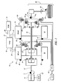
- Fig. 1 is a schematic diagram of an exemplary hybrid powertrain, in accordance with the present disclosure
- Fig. 2 is a schematic diagram of an exemplary architecture for a control system and hybrid powertrain, in accordance with the present disclosure
- Figs. 3 - 8 are schematic flow diagrams of a control scheme, in accordance with the present disclosure.
- Fig. 9 is a schematic power flow diagram, in accordance with the present disclosure.
- FIGs. 1 and 2 depict an exemplary electro-mechanical hybrid powertrain.
- the exemplary electro-mechanical hybrid powertrain in accordance with the present disclosure is depicted in Fig. 1 , comprising a two-mode, compound-split, electro-mechanical hybrid transmission 10 operatively connected to an engine 14 and torque generating machines comprising first and second electric machines ('MG-A') 56 and ('MG-B') 72.
- the engine 14 and the first and second electric machines 56 and 72 each generate mechanical power which can be transferred to the transmission 10.
- the power generated by the engine 14 and the first and second electric machines 56 and 72 and transferred to the transmission 10 is described in terms of input and motor torques, referred to herein as T I , T A , and T B respectively, and speed, referred to herein as N I , N A , and N B , respectively.
- the exemplary engine 14 comprises a multi-cylinder internal combustion engine selectively operative in several states to transfer torque to the transmission 10 via an input shaft 12, and can be either a spark-ignition or a compression-ignition engine.
- the engine 14 includes a crankshaft (not shown) operatively coupled to the input shaft 12 of the transmission 10.
- a rotational speed sensor 11 monitors rotational speed of the input shaft 12.
- Power output from the engine 14, comprising rotational speed and engine torque can differ from the input speed N I and the input torque T I to the transmission 10 due to placement of torque-consuming components on the input shaft 12 between the engine 14 and the transmission 10, e.g., a hydraulic pump (not shown) and/or a torque management device (not shown).
- the exemplary transmission 10 comprises three planetary-gear sets 24, 26 and 28, and four selectively engageable torque-transferring devices, i.e., clutches C1 70, C2 62, C3 73, and C4 75.
- clutches refer to any type of friction torque transfer device including single or compound plate clutches or packs, band clutches, and brakes, for example.
- a hydraulic control circuit 42 preferably controlled by a transmission control module (hereafter 'TCM') 17, is operative to control clutch states.
- Clutches C2 62 and C4 75 preferably comprise hydraulically-applied rotating friction clutches.
- Clutches C1 70 and C3 73 preferably comprise hydraulically-controlled stationary devices that can be selectively grounded to a transmission case 68.
- Each of the clutches C1 70, C2 62, C3 73, and C4 75 is preferably hydraulically applied, selectively receiving pressurized hydraulic fluid via the hydraulic control circuit 42.
- the first and second electric machines 56 and 72 preferably comprise three-phase AC machines, each including a stator (not shown) and a rotor (not shown), and respective resolvers 80 and 82.
- the motor stator for each machine is grounded to an outer portion of the transmission case 68, and includes a stator core with coiled electrical windings extending therefrom.
- the rotor for the first electric machine 56 is supported on a hub plate gear that is operatively attached to shaft 60 via the second planetary gear set 26.
- the rotor for the second electric machine 72 is fixedly attached to a sleeve shaft hub 66.
- Each of the resolvers 80 and 82 preferably comprises a variable reluctance device including a resolver stator (not shown) and a resolver rotor (not shown).
- the resolvers 80 and 82 are appropriately positioned and assembled on respective ones of the first and second electric machines 56 and 72.
- Stators of respective ones of the resolvers 80 and 82 are operatively connected to one of the stators for the first and second electric machines 56 and 72.
- the resolver rotors are operatively connected to the rotor for the corresponding first and second electric machines 56 and 72.
- Each of the resolvers 80 and 82 is signally and operatively connected to a transmission power inverter control module (hereafter 'TPIM') 19, and each senses and monitors rotational position of the resolver rotor relative to the resolver stator, thus monitoring rotational position of respective ones of first and second electric machines 56 and 72. Additionally, the signals output from the resolvers 80 and 82 are interpreted to provide the rotational speeds for first and second electric machines 56 and 72, i.e., N A and N B , respectively.
- the transmission 10 includes an output member 64, e.g. a shaft, which is operably connected to a driveline 90 for a vehicle (not shown), to provide output power to the driveline 90 that is transferred to vehicle wheels 93, one of which is shown in Fig. 1 .
- the output power at the output member 64 is characterized in terms of an output rotational speed No and an output torque T O .
- a transmission output speed sensor 84 monitors rotational speed and rotational direction of the output member 64.
- Each of the vehicle wheels 93 is preferably equipped with a friction brake 94 and a sensor (not shown) adapted to monitor wheel speed, V SS-WHL , the output of which is monitored by a control module of a distributed control module system described with respect to Fig. 2 , to determine vehicle speed, and absolute and relative wheel speeds for braking control, traction control, and vehicle acceleration management.
- the input torque from the engine 14 and the motor torques from the first and second electric machines 56 and 72 (T I , T A , and T B respectively) are generated as a result of energy conversion from fuel or electrical potential stored in an electrical energy storage device (hereafter 'ESD') 74.
- the ESD 74 is high voltage DC-coupled to the TPIM 19 via DC transfer conductors 27.
- the transfer conductors 27 include a contactor switch 38. When the contactor switch 38 is closed, under normal operation, electric current can flow between the ESD 74 and the TPIM 19. When the contactor switch 38 is opened electric current flow between the ESD 74 and the TPIM 19 is interrupted.
- the TPIM 19 transmits electrical power to and from the first electric machine 56 by transfer conductors 29, and the TPIM 19 similarly transmits electrical power to and from the second electric machine 72 by transfer conductors 31 to meet the torque commands for the first and second electric machines 56 and 72 in response to the motor torque commands T A and T B . Electrical current is transmitted to and from the ESD 74 in accordance with whether the ESD 74 is being charged or discharged.
- the TPIM 19 includes the pair of power inverters (not shown) and respective motor control modules (not shown) configured to receive the motor torque commands and control inverter states therefrom for providing motor drive or regeneration functionality to meet the commanded motor torques T A and T B .
- the power inverters comprise known complementary three-phase power electronics devices, and each includes a plurality of insulated gate bipolar transistors (not shown) for converting DC power from the ESD 74 to AC power for powering respective ones of the first and second electric machines 56 and 72, by switching at high frequencies.
- the insulated gate bipolar transistors form a switch mode power supply configured to receive control commands. There is typically one pair of insulated gate bipolar transistors for each phase of each of the three-phase electric machines.
- the three-phase inverters receive or supply DC electric power via DC transfer conductors 27 and transform it to or from three-phase AC power, which is conducted to or from the first and second electric machines 56 and 72 for operation as motors or generators via transfer conductors 29 and 31 respectively.
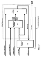
- Fig. 2 is a schematic block diagram of the distributed control module system.
- the elements described hereinafter comprise a subset of an overall vehicle control architecture, and provide coordinated system control of the exemplary hybrid powertrain described in Fig. 1 .
- the distributed control module system synthesizes pertinent information and inputs, and executes algorithms to control various actuators to meet control objectives, including objectives related to fuel economy, emissions, performance, drivability, and protection of hardware, including batteries of ESD 74 and the first and second electric machines 56 and 72.
- the distributed control module system includes an engine control module (hereafter 'ECM') 23, the TCM 17, a battery pack control module (hereafter ⁇ BPCM') 21, and the TPIM 19.
- 'ECM' engine control module
- ⁇ BPCM' battery pack control module
- a hybrid control module (hereafter 'HCP') 5 provides supervisory control and coordination of the ECM 23, the TCM 17, the BPCM 21, and the TPIM 19.
- a user interface ('UI') 13 is operatively connected to a plurality of devices through which a vehicle operator controls or directs operation of the electro-mechanical hybrid powertrain.
- the devices include an accelerator pedal 113 ('AP'), an operator brake pedal 112 ('BP'), a transmission gear selector 114 ('PRNDL'), and a vehicle speed cruise control (not shown).
- the transmission gear selector 114 may have a discrete number of operator-selectable positions, including the rotational direction of the output member 64 to enable one of a forward and a reverse direction.
- the aforementioned control modules communicate with other control modules, sensors, and actuators via a local area network (hereafter 'LAN') bus 6.
- the LAN bus 6 allows for structured communication of states of operating parameters and actuator command signals between the various control modules.
- the specific communication protocol utilized is application-specific.
- the LAN bus 6 and appropriate protocols provide for robust messaging and multi-control module interfacing between the aforementioned control modules, and other control modules providing functionality including e.g., antilock braking, traction control, and vehicle stability.
- Multiple communications buses may be used to improve communications speed and provide some level of signal redundancy and integrity. Communication between individual control modules can also be effected using a direct link, e.g., a serial peripheral interface ('SPI') bus (not shown).
- 'SPI' serial peripheral interface
- the HCP 5 provides supervisory control of the hybrid powertrain, serving to coordinate operation of the ECM 23, TCM 17, TPIM 19, and BPCM 21. Based upon various input signals from the user interface 13 and the hybrid powertrain, including the ESD 74, the HCP 5 determines an operator torque request, an output torque command, an engine input torque command, clutch torque(s) for the applied torque-transfer clutches C 1 70, C2 62, C3 73, C4 75 of the transmission 10, and the motor torque commands T A and T B for the first and second electric machines 56 and 72.
- the ECM 23 is operatively connected to the engine 14, and functions to acquire data from sensors and control actuators of the engine 14 over a plurality of discrete lines, shown for simplicity as an aggregate bidirectional interface cable 35.
- the ECM 23 receives the engine input torque command from the HCP 5.
- the ECM 23 determines the actual engine input torque, T I , provided to the transmission 10 at that point in time based upon monitored engine speed and load, which is communicated to the HCP 5.
- the ECM 23 monitors input from the rotational speed sensor 11 to determine the engine input speed to the input shaft 12, which translates to the transmission input speed, N I .
- the ECM 23 monitors inputs from sensors (not shown) to determine states of other engine operating parameters including, e.g., a manifold pressure, engine coolant temperature, ambient air temperature, and ambient pressure.
- the engine load can be determined, for example, from the manifold pressure, or alternatively, from monitoring operator input to the accelerator pedal 113.
- the ECM 23 generates and communicates command signals to control engine actuators, including, e.g., fuel injectors, ignition modules, and throttle control modules, none of which are shown.
- the TCM 17 is operatively connected to the transmission 10 and monitors inputs from sensors (not shown) to determine states of transmission operating parameters.
- the TCM 17 generates and communicates command signals to control the transmission 10, including controlling the hydraulic control circuit 42.
- Inputs from the TCM 17 to the HCP 5 include estimated clutch torques for each of the clutches, i.e., C 1 70, C2 62, C3 73, and C4 75, and rotational output speed, No, of the output member 64.
- Other actuators and sensors may be used to provide additional information from the TCM 17 to the HCP 5 for control purposes.
- the TCM 17 monitors inputs from pressure switches (not shown) and selectively actuates pressure control solenoids (not shown) and shift solenoids (not shown) of the hydraulic control circuit 42 to selectively actuate the various clutches C1 70, C2 62, C3 73, and C4 75 to achieve various transmission operating range states, as described hereinbelow.
- the BPCM 21 is signally connected to sensors (not shown) to monitor the ESD 74, including states of electrical current and voltage parameters, to provide information indicative of parametric states of the batteries of the ESD 74 to the HCP 5.
- the parametric states of the batteries preferably include battery state-of-charge, battery voltage, battery temperature, and available battery power, referred to as a range P BAT_MIN to P BAT_MAX .
- a brake control module (hereafter 'BrCM') 22 is operatively connected to friction brakes 94 on each of the vehicle wheels 93.
- the BrCM 22 monitors the operator input to the brake pedal 112 and generates control signals to control the friction brakes 94 and sends a control signal to the HCP 5 to operate the first and second electric machines 56 and 72 based thereon.
- Each of the control modules ECM 23, TCM 17, TPIM 19, BPCM 21, and BrCM 22 is preferably a general-purpose digital computer comprising a microprocessor or central processing unit, storage mediums comprising read only memory ('ROM'), random access memory ('RAM'), electrically programmable read only memory ('EPROM'), a high speed clock, analog to digital ('A/D') and digital to analog ('D/A') circuitry, and input/output circuitry and devices ('I/O') and appropriate signal conditioning and buffer circuitry.
- Each of the control modules has a set of control algorithms, comprising resident program instructions and calibrations stored in one of the storage mediums and executed to provide the respective functions of each computer.
- control algorithms are executed during preset loop cycles such that each algorithm is executed at least once each loop cycle.
- Algorithms stored in the non-volatile memory devices are executed by one of the central processing units to monitor inputs from the sensing devices and execute control and diagnostic routines to control operation of the actuators, using preset calibrations.
- Loop cycles are executed at regular intervals, for example each 3.125, 6.25, 12.5, 25 and 100 milliseconds during ongoing operation of the hybrid powertrain. Alternatively, algorithms may be executed in response to the occurrence of an event.
- the exemplary hybrid powertrain selectively operates in one of several states that can be described in terms of engine states comprising one of an engine-on state ('ON') and an engine-off state ('OFF'), and transmission operating range states comprising a plurality of fixed gears and continuously variable operating modes, described with reference to Table 1, below.
- Each of the transmission operating range states is described in the table and indicates which of the specific clutches C1 70, C2 62, C3 73, and C4 75 are applied for each of the operating range states.
- a first continuously variable mode i.e., EVT Mode 1, or M1 is selected by applying clutch C1 70 only in order to "ground” the outer gear member of the third planetary gear set 28.
- the engine state can be one of ON ('M1_Eng_On') or OFF ('M1_Eng_Off').
- a second continuously variable mode i.e., EVT Mode 2, or M2, is selected by applying clutch C2 62 only to connect the shaft 60 to the carrier of the third planetary gear set 28.
- the engine state can be one of ON ('M2_Eng_On') or OFF ('M2_Eng_Off").
- 'RPM' revolutions per minute
- a fixed gear operation provides a fixed ratio operation of input-to-output speed of the transmission 10, i.e., N I /N O .
- a first fixed gear operation ('G1') is selected by applying clutches C1 70 and C4 75.
- a second fixed gear operation ('G2') is selected by applying clutches C1 70 and C2 62.
- a third fixed gear operation ('G3') is selected by applying clutches C2 62 and C4 75.
- a fourth fixed gear operation ('G4') is selected by applying clutches C2 62 and C3 73.
- the fixed ratio operation of input-to-output speed increases with increased fixed gear operation due to decreased gear ratios in the planetary gears 24, 26, and 28.
- the rotational speeds of the first and second electric machines 56 and 72, N A and N B respectively, are dependent on internal rotation of the mechanism as defined by the clutching and are proportional to the input speed measured at the input shaft 12.
- the HCP 5 and one or more of the other control modules determine torque commands to control the torque generative devices comprising the engine 14 and the first and second electric machines 56 and 72 to meet the operator torque request at the output member 64 and transferred to the driveline 90.
- the HCP 5 determines the operator torque request, a commanded output torque from the transmission 10 to the driveline 90, the input torque from the engine 14, clutch torques for the torque-transfer clutches C1 70, C2 62, C3 73, C4 75 of the transmission 10; and the motor torques for the first and second electric machines 56 and 72, respectively, as is described hereinbelow.
- Final vehicle acceleration can be affected by other factors including, e.g., road load, road grade, and vehicle mass.
- the engine state and the transmission operating range state are determined based upon operating characteristics of the hybrid powertrain. This includes the operator torque request communicated through the accelerator pedal 113 and brake pedal 112 to the user interface 13 as previously described.
- the transmission operating range state and the engine state may be predicated on a hybrid powertrain torque demand caused by a command to operate the first and second electric machines 56 and 72 in an electrical energy generating mode or in a torque generating mode.
- the transmission operating range state and the engine state can be determined by an optimization algorithm or routine which determines optimum system efficiency based upon operator demand for power, battery state of charge, and energy efficiencies of the engine 14 and the first and second electric machines 56 and 72.
- the control system manages torque inputs from the engine 14 and the first and second electric machines 56 and 72 based upon an outcome of the executed optimization routine, and system efficiencies are optimized thereby, to manage fuel economy and battery charging. Furthermore, operation can be determined based upon a fault in a component or system.
- the HCP 5 monitors the torque-generative devices, and determines the power output from the transmission 10 at output member 64 that is required to meet the operator torque request while meeting other powertrain operating demands, e.g., charging the ESD 74.
- the ESD 74 and the first and second electric machines 56 and 72 are electrically-operatively coupled for power flow therebetween.
- the engine 14, the first and second electric machines 56 and 72, and the electro-mechanical transmission 10 are mechanically-operatively coupled to transfer power therebetween to generate a power flow to the output member 64.
- Fig. 3 shows a control system architecture for controlling and managing signal flow in a hybrid powertrain system having multiple torque generative devices, described hereinbelow with reference to the hybrid powertrain system of Figs. 1 and 2 , and residing in the aforementioned control modules in the form of executable algorithms and calibrations.
- the control system architecture is applicable to alternative hybrid powertrain systems having multiple torque generative devices, including, e.g., a hybrid powertrain system having an engine and a single electric machine, a hybrid powertrain system having an engine and multiple electric machines.
- the hybrid powertrain system can utilize non-electric torque-generative machines and energy storage systems, e.g., hydraulic-mechanical hybrid transmissions (not shown).
- the operator inputs to the accelerator pedal 113 and the brake pedal 112 are monitored to determine the operator torque request.
- the operator inputs to the accelerator pedal 113 and the brake pedal 112 comprise individually determinable operator torque request inputs including an immediate accelerator output torque request ('Output Torque Request Accel Immed'), a predicted accelerator output torque request ('Output Torque Request Accel Prdtd'), an immediate brake output torque request ('Output Torque Request Brake Immed'), a predicted brake output torque request ('Output Torque Request Brake Prdtd') and an axle torque response type ('Axle Torque Response Type').
- the term 'accelerator' refers to an operator request for forward propulsion preferably resulting in increasing vehicle speed over the present vehicle speed, when the operator selected position of the transmission gear selector 114 commands operation of the vehicle in the forward direction.
- the terms 'deceleration' and 'brake' refer to an operator request preferably resulting in decreasing vehicle speed from the present vehicle speed.
- the immediate accelerator output torque request, the predicted accelerator output torque request, the immediate brake output torque request, the predicted brake output torque request, and the axle torque response type are individual inputs to the control system. Additionally, operation of the engine 14 and the transmission 10 are monitored to determine the input speed ('Ni') and the output speed ('No').
- a strategic control scheme ('Strategic Control') 310 determines a preferred input speed ('Ni_Des') and a preferred engine state and transmission operating range state ('Hybrid Range State Des') based upon the output speed and the operator torque request and based upon other operating parameters of the hybrid powertrain, including battery power limits and response limits of the engine 14, the transmission 10, and the first and second electric machines 56 and 72.
- the predicted accelerator output torque request and the predicted brake output torque request are input to the strategic control scheme 310.
- the strategic control scheme 310 is preferably executed by the HCP 5 during each 100 ms loop cycle and each 25 ms loop cycle.
- the desired operating range state for the transmission 10 and the desired input speed from the engine 14 to the transmission 10 are inputs to the shift execution and engine start/stop control scheme 320.
- the shift execution and engine start/stop control scheme 320 commands changes in the transmission operation ('Transmission Commands') including changing the operating range state based upon the inputs and operation of the powertrain system. This includes commanding execution of a change in the transmission operating range state if the preferred operating range state is different from the present operating range state by commanding changes in application of one or more of the clutches C 1 70, C2 62, C3 73, and C4 75 and other transmission commands.
- the present operating range state ('Hybrid Range State Actual') and an input speed profile ('Ni_Prof) can be determined.
- the input speed profile is an estimate of an upcoming input speed and preferably comprises a scalar parametric value that is a targeted input speed for the forthcoming loop cycle.
- the engine operating commands and the operator torque request are based upon the input speed profile during a transition in the operating range state of the transmission.
- a tactical control scheme ('Tactical Control and Operation') 330 is repeatedly executed during one of the control loop cycles to determine engine commands ('Engine Commands') for operating the engine 14, including a preferred input torque from the engine 14 to the transmission 10 based upon the output speed, the input speed, and the operator torque request comprising the immediate accelerator output torque request, the predicted accelerator output torque request, the immediate brake output torque request, the predicted brake output torque request, the axle torque response type, and the present operating range state for the transmission.
- the engine commands also include engine states including one of an all-cylinder operating state and a cylinder deactivation operating state wherein a portion of the engine cylinders are deactivated and unfueled, and engine states including one of a fueled state and a fuel cutoff state.
- An engine command comprising the preferred input torque of the engine 14 and a present input torque ('Ti') reacting between the engine 14 and the input member 12 are preferably determined in the ECM 23.
- Clutch torques ('Tcl') for each of the clutches C1 70, C2 62, C3 73, and C4 75, including the presently applied clutches and the non-applied clutches are estimated, preferably in the TCM 17.
- An output and motor torque determination scheme ('Output and Motor Torque Determination') 340 is executed to determine the preferred output torque from the powertrain ('To_cmd'). This includes determining motor torque commands ('T A ', 'T B ') to transfer a net commanded output torque to the output member 64 of the transmission 10 that meets the operator torque request, by controlling the first and second electric machines 56 and 72 in this embodiment.
- the immediate accelerator output torque request, the immediate brake output torque request, the present input torque from the engine 14 and the estimated applied clutch torque(s), the present operating range state of the transmission 10, the input speed, the input speed profile, and the axle torque response type are inputs.
- the output and motor torque determination scheme 340 executes to determine the motor torque commands during each iteration of one of the loop cycles.
- the output and motor torque determination scheme 340 includes algorithmic code which is regularly executed during the 6.25 ms and 12.5 ms loop cycles to determine the preferred motor torque commands.
- the hybrid powertrain is controlled to transfer the output torque to the output member 64 to react with the driveline 90 to generate tractive torque at wheel(s) 93 to forwardly propel the vehicle in response to the operator input to the accelerator pedal 113 when the operator selected position of the transmission gear selector 114 commands operation of the vehicle in the forward direction.
- the hybrid powertrain is controlled to transfer the output torque to the output member 64 to react with the driveline 90 to generate tractive torque at wheel(s) 93 to propel the vehicle in a reverse direction in response to the operator input to the accelerator pedal 113 when the operator selected position of the transmission gear selector 114 commands operation of the vehicle in the reverse direction.
- propelling the vehicle results in vehicle acceleration so long as the output torque is sufficient to overcome external loads on the vehicle, e.g., due to road grade, aerodynamic loads, and other loads.
- FIG. 4 details signal flow in the strategic optimization control scheme 310, which includes a strategic manager 220, an operating range state analyzer 260, and a state stabilization and arbitration block 280 to determine the preferred input speed ('Ni_Des') and the preferred transmission operating range state ('Hybrid Range State Des').
- the strategic manager ('Strategic Manager') 220 monitors the output speed No, the predicted accelerator output torque request ('Output Torque Request Accel Prdtd'), the predicted brake output torque request ('Output Torque Request Brake Prdtd'), and available battery power P BAT_MIN to P BAT_MAX ⁇
- the strategic manager 220 determines which of the transmission operating range states are allowable, and determines output torque requests comprising a strategic accelerator output torque request ('Output Torque Request Accel Strategic') and a strategic net output torque request ('Output Torque Request Net Strategic'), all of which are input the operating range state analyzer 260 along with system inputs ('System Inputs') and power cost inputs ('Power Cost Inputs'), and any associated penalty costs ('Penalty Costs') for operating outside of predetermined limits.
- the operating range state analyzer 260 generates a preferred power cost ('P*cost') and associated input speed ('N*i') for each of the allowable operating range states based upon the operator torque requests, the system inputs, the available battery power and the power cost inputs.
- the preferred power costs and associated input speeds for the allowable operating range states are input to the state stabilization and arbitration block 280 which selects the preferred operating range state and preferred input speed based thereon.
- the operating range state analyzer 260 executes searches in each candidate operating range state comprising the allowable ones of the operating range states, including M1 (262), M2 (264), G1 (270), G2 (272), G3 (274), and G4 (276) to determine preferred operation of the torque actuators, i.e., the engine 14 and the first and second electric machines 56 and 72 in this embodiment.
- the preferred operation preferably comprises a minimum power cost for operating the hybrid powertrain system and an associated engine input for operating in the candidate operating range state in response to the operator torque request.
- the associated engine input comprises at least one of a preferred engine input speed ('Ni*'), a preferred engine input power ('Pi*'), and a preferred engine input torque ('Ti*') that is responsive to and preferably meets the operator torque request.
- the operating range state analyzer 260 evaluates M1-Engine-off (264) and M2-Engine-off (266) to determine a preferred cost ('P*cost') for operating the powertrain system responsive to and preferably meeting the operator torque request when the engine 14 is in the engine-off state.
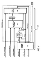
- Fig. 6 schematically shows signal flow for the 1-dimension search scheme 610.
- a range of one controllable input in this embodiment comprising minimum and maximum input torques ('TiMin/Max'), is input to a 1-D search engine 415.
- the 1-D search engine 415 iteratively generates candidate input torques ('Ti(j)') which range between the minimum and maximum input torques, each which is input to an optimization function ('Opt To/Ta/Tb') 440, for n search iterations.
- Other inputs to the optimization function 440 include system inputs preferably comprise parametric states for battery power, clutch torques, electric motor operation, transmission and engine operation, the specific operating range state and the operator torque request.
- the optimization function 440 determines transmission operation comprising an output torque, motor torques, and associated battery powers ('To(j), Ta(j), Tb(j), Pbat(j), Pa(j), Pb(j)') associated with the candidate input torque based upon the system inputs in response to the operator torque request for the candidate operating range state.
- the output torque, motor torques, and associated battery powers and power cost inputs are input to a cost function 450, which executes to determine a power cost ('Pcost(j)') for operating the powertrain in the candidate operating range state at the candidate input torque in response to the operator torque request.
- the 1-D search engine 415 iteratively generates candidate input torques over the range of input torques and determines the power costs associated therewith to identify a preferred input torque ('Ti*') and associated preferred cost ('P*cost').
- the preferred input torque ('Ti*') comprises the candidate input torque within the range of input torques that results in a minimum power cost of the candidate operating range state, i.e., the preferred cost.
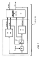
- Fig. 7 shows the preferred operation in each of continuously variable modes M1 and M2 executed in blocks 262 and 264 of the operating range state analyzer 260.
- This includes executing a 2-dimensional search scheme 620, shown with reference to Figs. 6 and 8 , in conjunction with executing a 1-dimensional search using the 1-dimensional search scheme 610 based upon a previously determined input speed which can be arbitrated ('Input Speed Stabilization and Arbitration') 615 to determine preferred costs ( ⁇ P*cost') and associated preferred input speeds ('N*i') for the operating range states.
- the 2-dimensional search scheme 620 determines a first preferred cost ('2D P*cost') and an associated first preferred input speed ('2D N*I').
- the first preferred input speed is input to the 2-dimensional search scheme 620 and to an adder.
- the adder sums the first preferred input speed and a time-rate change in the input speed ('N I_DOT ') multiplied by a predetermined time period ('dt').
- the resultant is input to a switch 605 along with the first preferred input speed determined by the 2-dimensional search scheme 620.
- the switch 605 is controlled to input either the resultant from the adder or the preferred input speed determined by the 2-dimensional search scheme 620 into the 1-dimensional search scheme 610.
- the switch 605 is controlled to input the preferred input speed determined by the 2-dimensional search scheme 620 into the 1-dimensional search scheme 610 (as shown) when the powertrain system is operating in a regenerative braking mode, e.g., when the operator torque request includes a request to generate an immediate output torque at the output member 64 to effect a reactive torque with the driveline 90 which preferably decelerates the vehicle.
- the switch 605 is controlled to a second position (not shown) to input the resultant from the adder when the operator torque request does not include regenerative braking.
- the 1-dimensional search scheme 610 is executed to determine a second preferred cost ('1D P*cost') using the 1-dimensional search scheme 610, which is input to the input speed stabilization and arbitration block 615 to select a final preferred cost and associated preferred input speed.
- Fig. 8 schematically shows signal flow for the 2-dimension search scheme 620.
- Ranges of two controllable inputs in this embodiment comprising minimum and maximum input speeds ('NiMin/Max') and minimum and maximum input powers ('PiMin/Max'), are input to a 2-D search engine 410.
- the two controllable inputs can comprise minimum and maximum input speeds and minimum and maximum input torques.
- the 2-D search engine 410 iteratively generates candidate input speeds ('Ni(j)') and candidate input powers ('Pi*(j)') which range between the minimum and maximum input speeds and powers.
- the candidate input power is preferably converted to a candidate input torque ('Ti(j)') (412).
- Each candidate input speed ('Ni(j)') and candidate input torque ('Ti(j)') are input to an optimization function ('Opt To/Ta/Tb') 440, for n search iterations.
- Other inputs to the optimization function 440 include system inputs preferably comprising parametric states for battery power, clutch torques, electric motor operation, transmission and engine operation, the specific operating range state and the operator torque request.
- the optimization function 440 determines transmission operation comprising an output torque, motor torques, and associated battery powers ('To(j), Ta(j), Tb(j), Pbat(j), Pa(j), Pb(j)') associated with the candidate input power and candidate input speed based upon the system inputs and the operating torque request for the candidate operating range state.
- the output torque, motor torques, and associated battery powers and power cost inputs are input to a cost function 450, which executes to determine a power cost ( ⁇ Pcost(j)') for operating the powertrain at the candidate input power and candidate input speed in response to the operator torque request in the candidate operating range state.
- the 2-D search engine 410 iteratively generates the candidate input powers and candidate input speeds over the range of input speeds and range of input powers and determines the power costs associated therewith to identify a preferred input power ('P*') and preferred input speed('Ni*') and associated preferred cost ('P*cost').
- the preferred input power ('P*') and preferred input speed ('N*') comprises the candidate input power and candidate input speed that result in a minimum power cost for the candidate operating range state.
- Fig. 9 schematically shows power flow and power losses through hybrid powertrain system, in context of the exemplary powertrain system described above.
- a fuel storage system 9 which transfers fuel power ('P FUEL ') to the engine 14 which transfers input power ('P I ') to the transmission 10.
- the power loss in the first flow path comprises engine power losses ("P LOSS ENC ').
- a second power flow path which transfers electric power ('P BAT ') from the ESD 74 to the TPIM 19 which transfers electric power ('P INV ELEC ') to the first and second electric machines 56 and 72 which transfer motor mechanical power ('P MOTOR MECH ') to the transmission 10.
- the power losses in the second power flow path include battery power losses ('P LOSS BATT') and electric motor power losses ("P LOSS MOTOR ') ⁇
- the TPIM 19 has an electric power load ('P HV LOAD ') that services electric loads in the system ('HV Loads'), which can include a low voltage battery storage system (not shown).
- the transmission 10 has a mechanical inertia power input ('P INERTIA ') in the system ('Inertia Storage') that preferably include inertias from the engine 14 and the transmission 10.
- the transmission 10 has mechanical power losses ('P LOSS MECH ') and power output ('P OUT ').
- the brake system 94 has brake power losses ('P LOSS BRAKE ') and the remaining power is transferred to the driveline as axle power ('P AXLE ').
- the power cost inputs to the cost function 450 are determined based upon factors related to vehicle driveability, fuel economy, emissions, and battery usage. Power costs are assigned and associated with fuel and electrical power consumption and are associated with a specific operating points of the hybrid powertrain. Lower operating costs can be associated with lower fuel consumption at high conversion efficiencies, lower battery power usage, and lower emissions for each engine speed/load operating point, and take into account the candidate operating state of the engine 14.
- the power costs may include the engine power losses ('P LOSS ENG '), electric motor power losses ('P LOSS MOTOR '), battery power losses ('P LOSS BATT '), brake power losses ('P LOSS BRAKE '), and mechanical power losses ('P LOSS MECH ') associated with operating the hybrid powertrain at a specific operating point which includes input speed, motor speeds, input torque, motor torques, a transmission operating range state and an engine state.
- engine power losses 'P LOSS ENG '
- electric motor power losses 'P LOSS MOTOR '
- battery power losses 'P LOSS BATT '
- brake power losses 'P LOSS BRAKE '
- mechanical power losses 'P LOSS MECH '
- the mechanical power loss in the transmission 10 includes power losses due to rotational spinning, torque transfer, and friction, and operation of parasitic loads, e.g., a hydraulic pump (not shown) for the transmission 10.
- the mechanical power loss can be determined for each operating range state for the transmission 14 at a selected input speed.
- the motor torque compensations described with reference to Eq. 3 can be determined during each iteration of the 2-dimensional search scheme 620 to determine the preferred input speed and preferred input power associated with system operation to achieve an output torque when operating in the selected continuously variable operating range state.
- a11, a21, b1, c1, and d1 are known scalar values predetermined for the system and the specific operating range state to compensate for the mechanical power loss
- [d1]N o represents the mechanical power loss.
- the output speed No is known, and Eq. 2 can be executed to determine , the mechanical power loss determined based upon the input speed Ni.
- the power cost input comprising the mechanical power loss to the cost function 450 can be predetermined outside of the 1-dimension search scheme 610, and the output torque compensation can be determined.
- the power cost input comprising the mechanical power loss to the cost function 450 can be determined during each iteration of the search scheme 620, and motor torque compensations for the first and second electric machines 56 and 72 can be determined.
Abstract
Description
- This application claims the benefit of
U.S. Provisional Application No. 60/985,375, filed on 11/05/2007 - This disclosure pertains to control systems for hybrid powertrain systems.
- The statements in this section merely provide background information related to the present disclosure and may not constitute prior art.
- Known hybrid powertrain architectures can include multiple torque-generative devices, including internal combustion engines and non-combustion machines, e.g., electric machines, which transmit torque through a transmission device to an output member. One exemplary hybrid powertrain includes a two-mode, compound-split, electro-mechanical transmission which utilizes an input member for receiving tractive torque from a prime mover power source, preferably an internal combustion engine, and an output member. The output member can be operatively connected to a driveline for a motor vehicle for transmitting tractive torque thereto. Machines, operative as motors or generators, can generate torque inputs to the transmission independently of a torque input from the internal combustion engine. The Machines may transform vehicle kinetic energy transmitted through the vehicle driveline to energy that is storable in an energy storage device. A control system monitors various inputs from the vehicle and the operator and provides operational control of the hybrid powertrain, including controlling transmission operating state and gear shifting, controlling the torque-generative devices, and regulating the power interchange among the energy storage device and the machines to manage outputs of the transmission, including torque and rotational speed.
- A powertrain system includes an engine coupled to an input member of a hybrid transmission. The hybrid transmission is operative to transmit torque between the input member and a torque generating machine and an output member. A method for controlling the powertrain system includes monitoring an operator torque request, determining an output torque command and an output speed of the output member, iteratively selecting candidate input speeds to the input member, determining mechanical power loss in the hybrid transmission for each of the candidate input speeds and the output speed, and selecting a preferred input speed comprising the candidate input speed that achieves a minimum mechanical power loss in the hybrid transmission at the output speed.
- One or more embodiments will now be described, by way of example, with reference to the accompanying drawings, in which:
-
Fig. 1 is a schematic diagram of an exemplary hybrid powertrain, in accordance with the present disclosure; -
Fig. 2 is a schematic diagram of an exemplary architecture for a control system and hybrid powertrain, in accordance with the present disclosure; -
Figs. 3 - 8 are schematic flow diagrams of a control scheme, in accordance with the present disclosure; and -
Fig. 9 is a schematic power flow diagram, in accordance with the present disclosure. - Referring now to the drawings, wherein the showings are for the purpose of illustrating certain exemplary embodiments only and not for the purpose of limiting the same,
Figs. 1 and2 depict an exemplary electro-mechanical hybrid powertrain. The exemplary electro-mechanical hybrid powertrain in accordance with the present disclosure is depicted inFig. 1 , comprising a two-mode, compound-split, electro-mechanical hybrid transmission 10 operatively connected to anengine 14 and torque generating machines comprising first and second electric machines ('MG-A') 56 and ('MG-B') 72. Theengine 14 and the first and secondelectric machines transmission 10. The power generated by theengine 14 and the first and secondelectric machines transmission 10 is described in terms of input and motor torques, referred to herein as TI, TA, and TB respectively, and speed, referred to herein as NI, NA, and NB, respectively. - The
exemplary engine 14 comprises a multi-cylinder internal combustion engine selectively operative in several states to transfer torque to thetransmission 10 via aninput shaft 12, and can be either a spark-ignition or a compression-ignition engine. Theengine 14 includes a crankshaft (not shown) operatively coupled to theinput shaft 12 of thetransmission 10. Arotational speed sensor 11 monitors rotational speed of theinput shaft 12. Power output from theengine 14, comprising rotational speed and engine torque, can differ from the input speed NI and the input torque TI to thetransmission 10 due to placement of torque-consuming components on theinput shaft 12 between theengine 14 and thetransmission 10, e.g., a hydraulic pump (not shown) and/or a torque management device (not shown). - The
exemplary transmission 10 comprises three planetary-gear sets clutches C1 70,C2 62,C3 73, andC4 75. As used herein, clutches refer to any type of friction torque transfer device including single or compound plate clutches or packs, band clutches, and brakes, for example. Ahydraulic control circuit 42, preferably controlled by a transmission control module (hereafter 'TCM') 17, is operative to control clutch states.Clutches C2 62 andC4 75 preferably comprise hydraulically-applied rotating friction clutches.Clutches C1 70 andC3 73 preferably comprise hydraulically-controlled stationary devices that can be selectively grounded to atransmission case 68. Each of theclutches C1 70,C2 62,C3 73, andC4 75 is preferably hydraulically applied, selectively receiving pressurized hydraulic fluid via thehydraulic control circuit 42. - The first and second
electric machines respective resolvers transmission case 68, and includes a stator core with coiled electrical windings extending therefrom. The rotor for the firstelectric machine 56 is supported on a hub plate gear that is operatively attached toshaft 60 via the secondplanetary gear set 26. The rotor for the secondelectric machine 72 is fixedly attached to asleeve shaft hub 66. - Each of the
resolvers resolvers electric machines resolvers electric machines electric machines resolvers electric machines resolvers electric machines - The
transmission 10 includes anoutput member 64, e.g. a shaft, which is operably connected to adriveline 90 for a vehicle (not shown), to provide output power to thedriveline 90 that is transferred tovehicle wheels 93, one of which is shown inFig. 1 . The output power at theoutput member 64 is characterized in terms of an output rotational speed No and an output torque TO. A transmissionoutput speed sensor 84 monitors rotational speed and rotational direction of theoutput member 64. Each of thevehicle wheels 93 is preferably equipped with afriction brake 94 and a sensor (not shown) adapted to monitor wheel speed, VSS-WHL, the output of which is monitored by a control module of a distributed control module system described with respect toFig. 2 , to determine vehicle speed, and absolute and relative wheel speeds for braking control, traction control, and vehicle acceleration management. - The input torque from the
engine 14 and the motor torques from the first and secondelectric machines 56 and 72 (TI, TA, and TB respectively) are generated as a result of energy conversion from fuel or electrical potential stored in an electrical energy storage device (hereafter 'ESD') 74. The ESD 74 is high voltage DC-coupled to the TPIM 19 viaDC transfer conductors 27. Thetransfer conductors 27 include acontactor switch 38. When thecontactor switch 38 is closed, under normal operation, electric current can flow between theESD 74 and theTPIM 19. When thecontactor switch 38 is opened electric current flow between theESD 74 and the TPIM 19 is interrupted. The TPIM 19 transmits electrical power to and from the firstelectric machine 56 bytransfer conductors 29, and theTPIM 19 similarly transmits electrical power to and from the secondelectric machine 72 bytransfer conductors 31 to meet the torque commands for the first and secondelectric machines ESD 74 in accordance with whether theESD 74 is being charged or discharged. - The TPIM 19 includes the pair of power inverters (not shown) and respective motor control modules (not shown) configured to receive the motor torque commands and control inverter states therefrom for providing motor drive or regeneration functionality to meet the commanded motor torques TA and TB. The power inverters comprise known complementary three-phase power electronics devices, and each includes a plurality of insulated gate bipolar transistors (not shown) for converting DC power from the
ESD 74 to AC power for powering respective ones of the first and secondelectric machines DC transfer conductors 27 and transform it to or from three-phase AC power, which is conducted to or from the first and secondelectric machines transfer conductors -
Fig. 2 is a schematic block diagram of the distributed control module system. The elements described hereinafter comprise a subset of an overall vehicle control architecture, and provide coordinated system control of the exemplary hybrid powertrain described inFig. 1 . The distributed control module system synthesizes pertinent information and inputs, and executes algorithms to control various actuators to meet control objectives, including objectives related to fuel economy, emissions, performance, drivability, and protection of hardware, including batteries of ESD 74 and the first and secondelectric machines TCM 17, a battery pack control module (hereafter `BPCM') 21, and theTPIM 19. A hybrid control module (hereafter 'HCP') 5 provides supervisory control and coordination of theECM 23, theTCM 17, theBPCM 21, and theTPIM 19. A user interface ('UI') 13 is operatively connected to a plurality of devices through which a vehicle operator controls or directs operation of the electro-mechanical hybrid powertrain. The devices include an accelerator pedal 113 ('AP'), an operator brake pedal 112 ('BP'), a transmission gear selector 114 ('PRNDL'), and a vehicle speed cruise control (not shown). Thetransmission gear selector 114 may have a discrete number of operator-selectable positions, including the rotational direction of theoutput member 64 to enable one of a forward and a reverse direction. - The aforementioned control modules communicate with other control modules, sensors, and actuators via a local area network (hereafter 'LAN')
bus 6. TheLAN bus 6 allows for structured communication of states of operating parameters and actuator command signals between the various control modules. The specific communication protocol utilized is application-specific. TheLAN bus 6 and appropriate protocols provide for robust messaging and multi-control module interfacing between the aforementioned control modules, and other control modules providing functionality including e.g., antilock braking, traction control, and vehicle stability. Multiple communications buses may be used to improve communications speed and provide some level of signal redundancy and integrity. Communication between individual control modules can also be effected using a direct link, e.g., a serial peripheral interface ('SPI') bus (not shown). - The
HCP 5 provides supervisory control of the hybrid powertrain, serving to coordinate operation of theECM 23,TCM 17,TPIM 19, andBPCM 21. Based upon various input signals from theuser interface 13 and the hybrid powertrain, including theESD 74, theHCP 5 determines an operator torque request, an output torque command, an engine input torque command, clutch torque(s) for the applied torque-transfer clutches C 1 70,C2 62,C3 73,C4 75 of thetransmission 10, and the motor torque commands TA and TB for the first and secondelectric machines - The
ECM 23 is operatively connected to theengine 14, and functions to acquire data from sensors and control actuators of theengine 14 over a plurality of discrete lines, shown for simplicity as an aggregatebidirectional interface cable 35. TheECM 23 receives the engine input torque command from theHCP 5. TheECM 23 determines the actual engine input torque, TI, provided to thetransmission 10 at that point in time based upon monitored engine speed and load, which is communicated to theHCP 5. TheECM 23 monitors input from therotational speed sensor 11 to determine the engine input speed to theinput shaft 12, which translates to the transmission input speed, NI. TheECM 23 monitors inputs from sensors (not shown) to determine states of other engine operating parameters including, e.g., a manifold pressure, engine coolant temperature, ambient air temperature, and ambient pressure. The engine load can be determined, for example, from the manifold pressure, or alternatively, from monitoring operator input to theaccelerator pedal 113. TheECM 23 generates and communicates command signals to control engine actuators, including, e.g., fuel injectors, ignition modules, and throttle control modules, none of which are shown. - The
TCM 17 is operatively connected to thetransmission 10 and monitors inputs from sensors (not shown) to determine states of transmission operating parameters. TheTCM 17 generates and communicates command signals to control thetransmission 10, including controlling thehydraulic control circuit 42. Inputs from theTCM 17 to theHCP 5 include estimated clutch torques for each of the clutches, i.e., C 1 70,C2 62,C3 73, andC4 75, and rotational output speed, No, of theoutput member 64. Other actuators and sensors may be used to provide additional information from theTCM 17 to theHCP 5 for control purposes. TheTCM 17 monitors inputs from pressure switches (not shown) and selectively actuates pressure control solenoids (not shown) and shift solenoids (not shown) of thehydraulic control circuit 42 to selectively actuate thevarious clutches C1 70,C2 62,C3 73, andC4 75 to achieve various transmission operating range states, as described hereinbelow. - The
BPCM 21 is signally connected to sensors (not shown) to monitor theESD 74, including states of electrical current and voltage parameters, to provide information indicative of parametric states of the batteries of theESD 74 to theHCP 5. The parametric states of the batteries preferably include battery state-of-charge, battery voltage, battery temperature, and available battery power, referred to as a range PBAT_MIN to PBAT_MAX. - A brake control module (hereafter 'BrCM') 22 is operatively connected to
friction brakes 94 on each of thevehicle wheels 93. TheBrCM 22 monitors the operator input to thebrake pedal 112 and generates control signals to control thefriction brakes 94 and sends a control signal to theHCP 5 to operate the first and secondelectric machines - Each of the
control modules ECM 23,TCM 17,TPIM 19,BPCM 21, andBrCM 22 is preferably a general-purpose digital computer comprising a microprocessor or central processing unit, storage mediums comprising read only memory ('ROM'), random access memory ('RAM'), electrically programmable read only memory ('EPROM'), a high speed clock, analog to digital ('A/D') and digital to analog ('D/A') circuitry, and input/output circuitry and devices ('I/O') and appropriate signal conditioning and buffer circuitry. Each of the control modules has a set of control algorithms, comprising resident program instructions and calibrations stored in one of the storage mediums and executed to provide the respective functions of each computer. Information transfer between the control modules is preferably accomplished using theLAN bus 6 and SPI buses. The control algorithms are executed during preset loop cycles such that each algorithm is executed at least once each loop cycle. Algorithms stored in the non-volatile memory devices are executed by one of the central processing units to monitor inputs from the sensing devices and execute control and diagnostic routines to control operation of the actuators, using preset calibrations. Loop cycles are executed at regular intervals, for example each 3.125, 6.25, 12.5, 25 and 100 milliseconds during ongoing operation of the hybrid powertrain. Alternatively, algorithms may be executed in response to the occurrence of an event. - The exemplary hybrid powertrain selectively operates in one of several states that can be described in terms of engine states comprising one of an engine-on state ('ON') and an engine-off state ('OFF'), and transmission operating range states comprising a plurality of fixed gears and continuously variable operating modes, described with reference to Table 1, below.
Table 1 Description Engine State Transmission Operating Range State Applied Clutches M1_Eng_Off OFF EVT Mode 1 C1 70M1_Eng_On ON EVT Mode 1 C1 70 G 1 ON Fixed Gear Ratio 1 C1 70C4 75G2 ON Fixed Gear Ratio 2 C1 70C2 62M2_Eng_Off OFF EVT Mode 2 C2 62M2_Eng_On ON EVT Mode 2 C2 62G3 ON Fixed Gear Ratio 3 C2 62C4 75G4 ON Fixed Gear Ratio 4 C2 62C3 73 - Each of the transmission operating range states is described in the table and indicates which of the
specific clutches C1 70,C2 62,C3 73, andC4 75 are applied for each of the operating range states. A first continuously variable mode, i.e., EVT Mode 1, or M1, is selected by applyingclutch C1 70 only in order to "ground" the outer gear member of the third planetary gear set 28. The engine state can be one of ON ('M1_Eng_On') or OFF ('M1_Eng_Off'). A second continuously variable mode, i.e., EVT Mode 2, or M2, is selected by applyingclutch C2 62 only to connect theshaft 60 to the carrier of the third planetary gear set 28. The engine state can be one of ON ('M2_Eng_On') or OFF ('M2_Eng_Off"). For purposes of this description, when the engine state is OFF, the engine input speed is equal to zero revolutions per minute ('RPM'), i.e., the engine crankshaft is not rotating. A fixed gear operation provides a fixed ratio operation of input-to-output speed of thetransmission 10, i.e., NI/NO. A first fixed gear operation ('G1') is selected by applyingclutches C1 70 andC4 75. A second fixed gear operation ('G2') is selected by applyingclutches C1 70 andC2 62. A third fixed gear operation ('G3') is selected by applyingclutches C2 62 andC4 75. A fourth fixed gear operation ('G4') is selected by applyingclutches C2 62 andC3 73. The fixed ratio operation of input-to-output speed increases with increased fixed gear operation due to decreased gear ratios in theplanetary gears electric machines input shaft 12. - In response to operator input via the
accelerator pedal 113 andbrake pedal 112 as captured by theuser interface 13, theHCP 5 and one or more of the other control modules determine torque commands to control the torque generative devices comprising theengine 14 and the first and secondelectric machines output member 64 and transferred to thedriveline 90. Based upon input signals from theuser interface 13 and the hybrid powertrain including theESD 74, theHCP 5 determines the operator torque request, a commanded output torque from thetransmission 10 to thedriveline 90, the input torque from theengine 14, clutch torques for the torque-transfer clutches C1 70,C2 62,C3 73,C4 75 of thetransmission 10; and the motor torques for the first and secondelectric machines - Final vehicle acceleration can be affected by other factors including, e.g., road load, road grade, and vehicle mass. The engine state and the transmission operating range state are determined based upon operating characteristics of the hybrid powertrain. This includes the operator torque request communicated through the
accelerator pedal 113 andbrake pedal 112 to theuser interface 13 as previously described. The transmission operating range state and the engine state may be predicated on a hybrid powertrain torque demand caused by a command to operate the first and secondelectric machines engine 14 and the first and secondelectric machines engine 14 and the first and secondelectric machines HCP 5 monitors the torque-generative devices, and determines the power output from thetransmission 10 atoutput member 64 that is required to meet the operator torque request while meeting other powertrain operating demands, e.g., charging theESD 74. As should be apparent from the description above, theESD 74 and the first and secondelectric machines engine 14, the first and secondelectric machines mechanical transmission 10 are mechanically-operatively coupled to transfer power therebetween to generate a power flow to theoutput member 64. -
Fig. 3 shows a control system architecture for controlling and managing signal flow in a hybrid powertrain system having multiple torque generative devices, described hereinbelow with reference to the hybrid powertrain system ofFigs. 1 and2 , and residing in the aforementioned control modules in the form of executable algorithms and calibrations. The control system architecture is applicable to alternative hybrid powertrain systems having multiple torque generative devices, including, e.g., a hybrid powertrain system having an engine and a single electric machine, a hybrid powertrain system having an engine and multiple electric machines. Alternatively, the hybrid powertrain system can utilize non-electric torque-generative machines and energy storage systems, e.g., hydraulic-mechanical hybrid transmissions (not shown). - In operation, the operator inputs to the
accelerator pedal 113 and thebrake pedal 112 are monitored to determine the operator torque request. The operator inputs to theaccelerator pedal 113 and thebrake pedal 112 comprise individually determinable operator torque request inputs including an immediate accelerator output torque request ('Output Torque Request Accel Immed'), a predicted accelerator output torque request ('Output Torque Request Accel Prdtd'), an immediate brake output torque request ('Output Torque Request Brake Immed'), a predicted brake output torque request ('Output Torque Request Brake Prdtd') and an axle torque response type ('Axle Torque Response Type'). As used herein, the term 'accelerator' refers to an operator request for forward propulsion preferably resulting in increasing vehicle speed over the present vehicle speed, when the operator selected position of thetransmission gear selector 114 commands operation of the vehicle in the forward direction. The terms 'deceleration' and 'brake' refer to an operator request preferably resulting in decreasing vehicle speed from the present vehicle speed. The immediate accelerator output torque request, the predicted accelerator output torque request, the immediate brake output torque request, the predicted brake output torque request, and the axle torque response type are individual inputs to the control system. Additionally, operation of theengine 14 and thetransmission 10 are monitored to determine the input speed ('Ni') and the output speed ('No'). - A strategic control scheme ('Strategic Control') 310 determines a preferred input speed ('Ni_Des') and a preferred engine state and transmission operating range state ('Hybrid Range State Des') based upon the output speed and the operator torque request and based upon other operating parameters of the hybrid powertrain, including battery power limits and response limits of the
engine 14, thetransmission 10, and the first and secondelectric machines strategic control scheme 310. Thestrategic control scheme 310 is preferably executed by theHCP 5 during each 100 ms loop cycle and each 25 ms loop cycle. The desired operating range state for thetransmission 10 and the desired input speed from theengine 14 to thetransmission 10 are inputs to the shift execution and engine start/stop control scheme 320. - The shift execution and engine start/
stop control scheme 320 commands changes in the transmission operation ('Transmission Commands') including changing the operating range state based upon the inputs and operation of the powertrain system. This includes commanding execution of a change in the transmission operating range state if the preferred operating range state is different from the present operating range state by commanding changes in application of one or more of the clutches C 1 70,C2 62,C3 73, andC4 75 and other transmission commands. The present operating range state ('Hybrid Range State Actual') and an input speed profile ('Ni_Prof) can be determined. The input speed profile is an estimate of an upcoming input speed and preferably comprises a scalar parametric value that is a targeted input speed for the forthcoming loop cycle. The engine operating commands and the operator torque request are based upon the input speed profile during a transition in the operating range state of the transmission. - A tactical control scheme ('Tactical Control and Operation') 330 is repeatedly executed during one of the control loop cycles to determine engine commands ('Engine Commands') for operating the
engine 14, including a preferred input torque from theengine 14 to thetransmission 10 based upon the output speed, the input speed, and the operator torque request comprising the immediate accelerator output torque request, the predicted accelerator output torque request, the immediate brake output torque request, the predicted brake output torque request, the axle torque response type, and the present operating range state for the transmission. The engine commands also include engine states including one of an all-cylinder operating state and a cylinder deactivation operating state wherein a portion of the engine cylinders are deactivated and unfueled, and engine states including one of a fueled state and a fuel cutoff state. An engine command comprising the preferred input torque of theengine 14 and a present input torque ('Ti') reacting between theengine 14 and theinput member 12 are preferably determined in theECM 23. Clutch torques ('Tcl') for each of theclutches C1 70,C2 62,C3 73, andC4 75, including the presently applied clutches and the non-applied clutches are estimated, preferably in theTCM 17. - An output and motor torque determination scheme ('Output and Motor Torque Determination') 340 is executed to determine the preferred output torque from the powertrain ('To_cmd'). This includes determining motor torque commands ('TA', 'TB') to transfer a net commanded output torque to the
output member 64 of thetransmission 10 that meets the operator torque request, by controlling the first and secondelectric machines engine 14 and the estimated applied clutch torque(s), the present operating range state of thetransmission 10, the input speed, the input speed profile, and the axle torque response type are inputs. The output and motor torque determination scheme 340 executes to determine the motor torque commands during each iteration of one of the loop cycles. The output and motor torque determination scheme 340 includes algorithmic code which is regularly executed during the 6.25 ms and 12.5 ms loop cycles to determine the preferred motor torque commands. - The hybrid powertrain is controlled to transfer the output torque to the
output member 64 to react with thedriveline 90 to generate tractive torque at wheel(s) 93 to forwardly propel the vehicle in response to the operator input to theaccelerator pedal 113 when the operator selected position of thetransmission gear selector 114 commands operation of the vehicle in the forward direction. Similarly, the hybrid powertrain is controlled to transfer the output torque to theoutput member 64 to react with thedriveline 90 to generate tractive torque at wheel(s) 93 to propel the vehicle in a reverse direction in response to the operator input to theaccelerator pedal 113 when the operator selected position of thetransmission gear selector 114 commands operation of the vehicle in the reverse direction. Preferably, propelling the vehicle results in vehicle acceleration so long as the output torque is sufficient to overcome external loads on the vehicle, e.g., due to road grade, aerodynamic loads, and other loads. -
FIG. 4 details signal flow in the strategicoptimization control scheme 310, which includes astrategic manager 220, an operatingrange state analyzer 260, and a state stabilization and arbitration block 280 to determine the preferred input speed ('Ni_Des') and the preferred transmission operating range state ('Hybrid Range State Des'). The strategic manager ('Strategic Manager') 220 monitors the output speed No, the predicted accelerator output torque request ('Output Torque Request Accel Prdtd'), the predicted brake output torque request ('Output Torque Request Brake Prdtd'), and available battery power PBAT_MIN to PBAT_MAX· Thestrategic manager 220 determines which of the transmission operating range states are allowable, and determines output torque requests comprising a strategic accelerator output torque request ('Output Torque Request Accel Strategic') and a strategic net output torque request ('Output Torque Request Net Strategic'), all of which are input the operatingrange state analyzer 260 along with system inputs ('System Inputs') and power cost inputs ('Power Cost Inputs'), and any associated penalty costs ('Penalty Costs') for operating outside of predetermined limits. The operatingrange state analyzer 260 generates a preferred power cost ('P*cost') and associated input speed ('N*i') for each of the allowable operating range states based upon the operator torque requests, the system inputs, the available battery power and the power cost inputs. The preferred power costs and associated input speeds for the allowable operating range states are input to the state stabilization and arbitration block 280 which selects the preferred operating range state and preferred input speed based thereon. The operatingrange state analyzer 260 executes searches in each candidate operating range state comprising the allowable ones of the operating range states, including M1 (262), M2 (264), G1 (270), G2 (272), G3 (274), and G4 (276) to determine preferred operation of the torque actuators, i.e., theengine 14 and the first and secondelectric machines range state analyzer 260 evaluates M1-Engine-off (264) and M2-Engine-off (266) to determine a preferred cost ('P*cost') for operating the powertrain system responsive to and preferably meeting the operator torque request when theengine 14 is in the engine-off state. -
Fig. 6 schematically shows signal flow for the 1-dimension search scheme 610. A range of one controllable input, in this embodiment comprising minimum and maximum input torques ('TiMin/Max'), is input to a 1-D search engine 415. The 1-D search engine 415 iteratively generates candidate input torques ('Ti(j)') which range between the minimum and maximum input torques, each which is input to an optimization function ('Opt To/Ta/Tb') 440, for n search iterations. Other inputs to theoptimization function 440 include system inputs preferably comprise parametric states for battery power, clutch torques, electric motor operation, transmission and engine operation, the specific operating range state and the operator torque request. Theoptimization function 440 determines transmission operation comprising an output torque, motor torques, and associated battery powers ('To(j), Ta(j), Tb(j), Pbat(j), Pa(j), Pb(j)') associated with the candidate input torque based upon the system inputs in response to the operator torque request for the candidate operating range state. The output torque, motor torques, and associated battery powers and power cost inputs are input to acost function 450, which executes to determine a power cost ('Pcost(j)') for operating the powertrain in the candidate operating range state at the candidate input torque in response to the operator torque request. The 1-D search engine 415 iteratively generates candidate input torques over the range of input torques and determines the power costs associated therewith to identify a preferred input torque ('Ti*') and associated preferred cost ('P*cost'). The preferred input torque ('Ti*') comprises the candidate input torque within the range of input torques that results in a minimum power cost of the candidate operating range state, i.e., the preferred cost. -
Fig. 7 shows the preferred operation in each of continuously variable modes M1 and M2 executed inblocks range state analyzer 260. This includes executing a 2-dimensional search scheme 620, shown with reference toFigs. 6 and8 , in conjunction with executing a 1-dimensional search using the 1-dimensional search scheme 610 based upon a previously determined input speed which can be arbitrated ('Input Speed Stabilization and Arbitration') 615 to determine preferred costs (`P*cost') and associated preferred input speeds ('N*i') for the operating range states. As described with reference toFig. 8 , the 2-dimensional search scheme 620 determines a first preferred cost ('2D P*cost') and an associated first preferred input speed ('2D N*I'). The first preferred input speed is input to the 2-dimensional search scheme 620 and to an adder. The adder sums the first preferred input speed and a time-rate change in the input speed ('NI_DOT') multiplied by a predetermined time period ('dt'). The resultant is input to aswitch 605 along with the first preferred input speed determined by the 2-dimensional search scheme 620. Theswitch 605 is controlled to input either the resultant from the adder or the preferred input speed determined by the 2-dimensional search scheme 620 into the 1-dimensional search scheme 610. Theswitch 605 is controlled to input the preferred input speed determined by the 2-dimensional search scheme 620 into the 1-dimensional search scheme 610 (as shown) when the powertrain system is operating in a regenerative braking mode, e.g., when the operator torque request includes a request to generate an immediate output torque at theoutput member 64 to effect a reactive torque with thedriveline 90 which preferably decelerates the vehicle. Theswitch 605 is controlled to a second position (not shown) to input the resultant from the adder when the operator torque request does not include regenerative braking. The 1-dimensional search scheme 610 is executed to determine a second preferred cost ('1D P*cost') using the 1-dimensional search scheme 610, which is input to the input speed stabilization and arbitration block 615 to select a final preferred cost and associated preferred input speed. -
Fig. 8 schematically shows signal flow for the 2-dimension search scheme 620. Ranges of two controllable inputs, in this embodiment comprising minimum and maximum input speeds ('NiMin/Max') and minimum and maximum input powers ('PiMin/Max'), are input to a 2-D search engine 410. In another embodiment, the two controllable inputs can comprise minimum and maximum input speeds and minimum and maximum input torques. The 2-D search engine 410 iteratively generates candidate input speeds ('Ni(j)') and candidate input powers ('Pi*(j)') which range between the minimum and maximum input speeds and powers. The candidate input power is preferably converted to a candidate input torque ('Ti(j)') (412). Each candidate input speed ('Ni(j)') and candidate input torque ('Ti(j)') are input to an optimization function ('Opt To/Ta/Tb') 440, for n search iterations. Other inputs to theoptimization function 440 include system inputs preferably comprising parametric states for battery power, clutch torques, electric motor operation, transmission and engine operation, the specific operating range state and the operator torque request. Theoptimization function 440 determines transmission operation comprising an output torque, motor torques, and associated battery powers ('To(j), Ta(j), Tb(j), Pbat(j), Pa(j), Pb(j)') associated with the candidate input power and candidate input speed based upon the system inputs and the operating torque request for the candidate operating range state. The output torque, motor torques, and associated battery powers and power cost inputs are input to acost function 450, which executes to determine a power cost (`Pcost(j)') for operating the powertrain at the candidate input power and candidate input speed in response to the operator torque request in the candidate operating range state. The 2-D search engine 410 iteratively generates the candidate input powers and candidate input speeds over the range of input speeds and range of input powers and determines the power costs associated therewith to identify a preferred input power ('P*') and preferred input speed('Ni*') and associated preferred cost ('P*cost'). The preferred input power ('P*') and preferred input speed ('N*') comprises the candidate input power and candidate input speed that result in a minimum power cost for the candidate operating range state. - [0001]
Fig. 9 schematically shows power flow and power losses through hybrid powertrain system, in context of the exemplary powertrain system described above. There is a first power flow path from afuel storage system 9 which transfers fuel power ('PFUEL') to theengine 14 which transfers input power ('PI') to thetransmission 10. The power loss in the first flow path comprises engine power losses ("PLOSS ENC'). There is a second power flow path which transfers electric power ('PBAT') from theESD 74 to theTPIM 19 which transfers electric power ('PINV ELEC') to the first and secondelectric machines transmission 10. The power losses in the second power flow path include battery power losses ('PLOSS BATT') and electric motor power losses ("PLOSS MOTOR')· TheTPIM 19 has an electric power load ('PHV LOAD') that services electric loads in the system ('HV Loads'), which can include a low voltage battery storage system (not shown). Thetransmission 10 has a mechanical inertia power input ('PINERTIA') in the system ('Inertia Storage') that preferably include inertias from theengine 14 and thetransmission 10. Thetransmission 10 has mechanical power losses ('PLOSS MECH') and power output ('POUT'). Thebrake system 94 has brake power losses ('PLOSS BRAKE') and the remaining power is transferred to the driveline as axle power ('PAXLE'). - [0002] The power cost inputs to the
cost function 450 are determined based upon factors related to vehicle driveability, fuel economy, emissions, and battery usage. Power costs are assigned and associated with fuel and electrical power consumption and are associated with a specific operating points of the hybrid powertrain. Lower operating costs can be associated with lower fuel consumption at high conversion efficiencies, lower battery power usage, and lower emissions for each engine speed/load operating point, and take into account the candidate operating state of theengine 14. As described hereinabove, the power costs may include the engine power losses ('PLOSS ENG'), electric motor power losses ('PLOSS MOTOR'), battery power losses ('PLOSS BATT'), brake power losses ('PLOSS BRAKE'), and mechanical power losses ('PLOSS MECH') associated with operating the hybrid powertrain at a specific operating point which includes input speed, motor speeds, input torque, motor torques, a transmission operating range state and an engine state. - The mechanical power loss in the
transmission 10 includes power losses due to rotational spinning, torque transfer, and friction, and operation of parasitic loads, e.g., a hydraulic pump (not shown) for thetransmission 10. - The mechanical power loss can be determined for each operating range state for the
transmission 14 at a selected input speed. When operating in one of the continuously variable operating range states, i.e., M1 and M2 in one embodiment, mechanical power loss related to the input speed ('Ni') and the output speed ('No') can be represented by Eq. 1:
wherein a, b, c, and d comprise calibrated scalar values determined for the specific powertrain system and for each transmission operating range state for the specific powertrain system. For a given input speed Ni the mechanical power loss can be reduced to:
wherein a0, a1, and a2 comprise scalar values based upon a, b, c, and d above and Ni is the candidate input speed for a specific iteration. The relationship of Eq. 2 is valid to determine the mechanical power loss in thetransmission 10 operating in one of the fixed gear operating range states for an input speed Ni necessary to achieve an output speed No. The relationship of Eq. 2 is valid to determine the mechanical power loss in thetransmission 10 operating in one of the continuously variable mode operating range states when the output speed No is known for any selected or candidate input speed Ni. - Motor torque compensations for the first and second
electric machines 
wherein the terms a11-a24 and b1, b2, c1, and c2 are known scalar values precalibrated for the specific system, and Ṅi and Ṅo are time-rate changes in the input and output speeds. When operating in one of the continuously variable operating range states, the motor torque compensations described with reference to Eq. 3 can be determined during each iteration of the 2-dimensional search scheme 620 to determine the preferred input speed and preferred input power associated with system operation to achieve an output torque when operating in the selected continuously variable operating range state. - When operating in one of the fixed gear operating range states, i.e., G1, G2, G3, and G4 for one embodiment, mechanical power loss related to the input speed ('Ni')and the output speed ('No') is represented by Eq. 2, above. For any output speed No the candidate input speed Ni is known for each fixed gear operating range state. The output torque compensation associated with operating in one of the fixed gear operating range states can be determined prior to execution of the 1-
D search scheme 610 to determine the input torque required to achieve the output torque. The output torque compensation in fixed gear can be determined as:
wherein a11, a21, b1, c1, and d1 are known scalar values predetermined for the system and the specific operating range state to compensate for the mechanical power loss, and the term [d1]No represents the mechanical power loss. - For the 1-
D search engine 415 and each execution of the 2-D search engine 410 , the output speed No is known, and Eq. 2 can be executed to determine , the mechanical power loss determined based upon the input speed Ni. Thus, in fixed gear operation, i.e., in one of the fixed gear operating ranges states of G1, G2, G3 and G4 for the embodiment described herein, the power cost input comprising the mechanical power loss to thecost function 450 can be predetermined outside of the 1-dimension search scheme 610, and the output torque compensation can be determined. In mode operation, i.e., in one of the mode operating ranges states of M1 and M2 for the embodiment described herein, the power cost input comprising the mechanical power loss to thecost function 450 can be determined during each iteration of thesearch scheme 620, and motor torque compensations for the first and secondelectric machines - It is understood that modifications are allowable within the scope of the disclosure. The disclosure has been described with specific reference to the preferred embodiments and modifications thereto. Further modifications and alterations may occur to others upon reading and understanding the specification. It is intended to include all such modifications and alterations insofar as they come within the scope of the disclosure.
Claims (12)
- Method for controlling a powertrain system including an engine coupled to an input member of a hybrid transmission, the hybrid transmission operative to transmit torque between the input member and a torque generating machine and an output member, the method comprising:monitoring an operator torque request;determining an output torque command and an output speed of the output member;iteratively selecting candidate input speeds to the input member;determining mechanical power loss in the hybrid transmission for each of the candidate input speeds and the output speed; andselecting a preferred input speed comprising the candidate input speed that achieves a minimum mechanical power loss in the hybrid transmission at the output speed.
- The method of claim 1, further comprising the transmission operative in one of a plurality of operating range states to transfer power between the input member and the torque generating machine and the output member, comprising:selecting candidate operating range states;iteratively selecting candidate input speeds to the input member for each of the candidate operating range states;determining mechanical power loss in the hybrid transmission in each of the candidate operating range states for each of the candidate input speeds;selecting a preferred input speed comprising the candidate input speed that achieves a minimum mechanical power loss in the hybrid transmission at the candidate operating range state for each of the selected operating range states; andselecting a preferred operating range state comprising the candidate operating range state having the minimum preferred input speed.
- The method of claim 2, further comprising determining a preferred motor torque command to the torque generating machine based upon the mechanical power loss in the hybrid transmission and the operator torque request.
- The method of claim 2, further comprising:selecting a fixed gear operating range state;determining the candidate input speed for the fixed gear operating range state based upon the output speed of the output member;determining a mechanical power loss in the hybrid transmission for the candidate input speed;determining a range of input torque to the hybrid transmission;executing a search within the range of input torques to the transmission including
selecting a candidate input torque,
determining preferred candidate output torque and a candidate motor torque for the torque generative machine associated with the candidate input torque, and
determining a power cost based upon the mechanical power loss for the hybrid transmission operating at the candidate output torque at the candidate input speed; andselecting a preferred input torque that achieves a minimum power cost. - The method of claim 2, further comprising:selecting a continuously variable operating range state;determining a range of input speed and a range of input power to the hybrid transmission;executing a search within the ranges of input speed and input power to the transmission including
selecting a candidate input power and a candidate input speed, determining a preferred candidate input torque,
determining a candidate motor torque for the torque generative machine based upon the candidate input torque,
determining a power cost based upon the mechanical power loss for the hybrid transmission operating at the candidate output power at the candidate input speed; andselecting a preferred input speed and input power that achieves a minimum power cost. - The method of claim 1, further comprising controlling motor torque output from the torque generating machine to compensate for the mechanical power loss in the hybrid transmission operating at the preferred input speed at the output speed.
- Method for controlling a powertrain system including an engine coupled to an input member of a hybrid transmission, the hybrid transmission operative to transmit torque between the input member and first and second electric machines and an output member, the method comprising:monitoring an operator torque request;determining an output torque command and an output speed of the output member;iteratively selecting candidate input speeds to the input member; determining mechanical power loss in the hybrid transmission for each of the candidate input speeds and the output speed; andselecting a preferred input speed comprising the candidate input speed that achieves a minimum mechanical power loss in the hybrid transmission at the output speed.
- The method of claim 7, wherein the transmission is operative in one of a plurality of operating range states to transfer power between the input member and the first and second electric machines and the output member, the method further comprising:selecting candidate operating range states;iteratively selecting candidate input speeds to the input member for each of the candidate operating range states;determining mechanical power loss in the hybrid transmission in each of the candidate operating range states for each of the candidate input speeds;selecting a preferred input speed comprising the candidate input speed that achieves a minimum mechanical power loss in the hybrid transmission at the candidate operating range state for each of the selected operating range states; andselecting a preferred operating range state comprising the candidate operating range state having the minimum preferred input speed.
- The method of claim 8, further comprising determining preferred motor torque commands to the first and second electric machines based upon the mechanical power loss in the hybrid transmission and the operator torque request.
- The method of claim 8, further comprising:selecting a fixed gear operating range state;determining the candidate input speed for the fixed gear operating range state based upon the output speed of the output member;determining a mechanical power loss in the hybrid transmission for the candidate input speed;determining a range of input torque to the hybrid transmission;executing a search within the range of input torques to the transmission including
selecting a candidate input torque,
determining preferred candidate output torque and candidate motor torques for the first and second electric machines associated with the candidate input torque, and
determining a power cost based upon the mechanical power loss for the hybrid transmission operating at the candidate output torque at the candidate input speed; andselecting a preferred input torque that achieves a minimum power cost. - The method of claim 8, further comprisingselecting a continuously variable operating range state;determining a range of input speed and a range of input power to the hybrid transmission;executing a search within the ranges of input speed and input power to the transmission including
selecting a candidate input power and a candidate input speed, determining a preferred candidate input torque,
determining candidate motor torques for the first and second electric machines based upon the candidate input torque,
determining a power cost based upon the mechanical power loss for the hybrid transmission operating at the candidate output power at the candidate input speed; and
selecting a preferred input speed and input power that achieves a minimum power cost. - The method of claim 7, further comprising controlling motor torques output from the first and second electric machines to compensate for the mechanical power loss in the hybrid transmission operating at the preferred input speed at the output speed.
Applications Claiming Priority (2)
| Application Number | Priority Date | Filing Date | Title |
|---|---|---|---|
| US98537507P | 2007-11-05 | 2007-11-05 | |
| US12/251,439 US8165777B2 (en) | 2007-11-05 | 2008-10-14 | Method to compensate for transmission spin loss for a hybrid powertrain system |
Publications (3)
| Publication Number | Publication Date |
|---|---|
| EP2055583A2 true EP2055583A2 (en) | 2009-05-06 |
| EP2055583A3 EP2055583A3 (en) | 2010-09-29 |
| EP2055583B1 EP2055583B1 (en) | 2015-04-08 |
Family
ID=40446230
Family Applications (1)
| Application Number | Title | Priority Date | Filing Date |
|---|---|---|---|
| EP08019062.2A Active EP2055583B1 (en) | 2007-11-05 | 2008-10-30 | Method for compensation of transmission spin loss for a hybrid powertrain system |
Country Status (3)
| Country | Link |
|---|---|
| US (1) | US8165777B2 (en) |
| EP (1) | EP2055583B1 (en) |
| CN (1) | CN101497338B (en) |
Cited By (1)
| Publication number | Priority date | Publication date | Assignee | Title |
|---|---|---|---|---|
| WO2014149710A1 (en) | 2013-03-15 | 2014-09-25 | Allison Transmission, Inc. | System and method for energy rate balancing in hybrid automatic transmsissions |
Families Citing this family (122)
| Publication number | Priority date | Publication date | Assignee | Title |
|---|---|---|---|---|
| US8390240B2 (en) | 2007-08-06 | 2013-03-05 | GM Global Technology Operations LLC | Absolute position sensor for field-oriented control of an induction motor |
| US7867135B2 (en) | 2007-09-26 | 2011-01-11 | GM Global Technology Operations LLC | Electro-mechanical transmission control system |
| US8234048B2 (en) | 2007-10-19 | 2012-07-31 | GM Global Technology Operations LLC | Method and system for inhibiting operation in a commanded operating range state for a transmission of a powertrain system |
| US9140337B2 (en) | 2007-10-23 | 2015-09-22 | GM Global Technology Operations LLC | Method for model based clutch control and torque estimation |
| US8060267B2 (en) | 2007-10-23 | 2011-11-15 | GM Global Technology Operations LLC | Method for controlling power flow within a powertrain system |
| US8335623B2 (en) | 2007-10-25 | 2012-12-18 | GM Global Technology Operations LLC | Method and apparatus for remediation of and recovery from a clutch slip event in a hybrid powertrain system |
| US8265821B2 (en) | 2007-10-25 | 2012-09-11 | GM Global Technology Operations LLC | Method for determining a voltage level across an electric circuit of a powertrain |
| US8296027B2 (en) | 2007-10-25 | 2012-10-23 | GM Global Technology Operations LLC | Method and apparatus to control off-going clutch torque during torque phase for a hybrid powertrain system |
| US8118122B2 (en) | 2007-10-25 | 2012-02-21 | GM Global Technology Operations LLC | Method and system for monitoring signal integrity in a distributed controls system |
| US8187145B2 (en) | 2007-10-25 | 2012-05-29 | GM Global Technology Operations LLC | Method and apparatus for clutch torque control in mode and fixed gear for a hybrid powertrain system |
| US8406945B2 (en) | 2007-10-26 | 2013-03-26 | GM Global Technology Operations LLC | Method and apparatus to control logic valves for hydraulic flow control in an electro-mechanical transmission |
| US8167773B2 (en) | 2007-10-26 | 2012-05-01 | GM Global Technology Operations LLC | Method and apparatus to control motor cooling in an electro-mechanical transmission |
| US8303463B2 (en) | 2007-10-26 | 2012-11-06 | GM Global Technology Operations LLC | Method and apparatus to control clutch fill pressure in an electro-mechanical transmission |
| US8204702B2 (en) | 2007-10-26 | 2012-06-19 | GM Global Technology Operations LLC | Method for estimating battery life in a hybrid powertrain |
| US9097337B2 (en) | 2007-10-26 | 2015-08-04 | GM Global Technology Operations LLC | Method and apparatus to control hydraulic line pressure in an electro-mechanical transmission |
| US8560191B2 (en) | 2007-10-26 | 2013-10-15 | GM Global Technology Operations LLC | Method and apparatus to control clutch pressures in an electro-mechanical transmission |
| US8548703B2 (en) | 2007-10-26 | 2013-10-01 | GM Global Technology Operations LLC | Method and apparatus to determine clutch slippage in an electro-mechanical transmission |
| US7985154B2 (en) * | 2007-10-26 | 2011-07-26 | GM Global Technology Operations LLC | Method and apparatus to control hydraulic pressure for component lubrication in an electro-mechanical transmission |
| US8428816B2 (en) | 2007-10-27 | 2013-04-23 | GM Global Technology Operations LLC | Method and apparatus for monitoring software and signal integrity in a distributed control module system for a powertrain system |
| US8244426B2 (en) | 2007-10-27 | 2012-08-14 | GM Global Technology Operations LLC | Method and apparatus for monitoring processor integrity in a distributed control module system for a powertrain system |
| US8099219B2 (en) | 2007-10-27 | 2012-01-17 | GM Global Technology Operations LLC | Method and apparatus for securing an operating range state mechanical transmission |
| US8062174B2 (en) | 2007-10-27 | 2011-11-22 | GM Global Technology Operations LLC | Method and apparatus to control clutch stroke volume in an electro-mechanical transmission |
| US8170762B2 (en) | 2007-10-29 | 2012-05-01 | GM Global Technology Operations LLC | Method and apparatus to control operation of a hydraulic pump for an electro-mechanical transmission |
| US8112194B2 (en) | 2007-10-29 | 2012-02-07 | GM Global Technology Operations LLC | Method and apparatus for monitoring regenerative operation in a hybrid powertrain system |
| US8095254B2 (en) | 2007-10-29 | 2012-01-10 | GM Global Technology Operations LLC | Method for determining a power constraint for controlling a powertrain system |
| US8290681B2 (en) | 2007-10-29 | 2012-10-16 | GM Global Technology Operations LLC | Method and apparatus to produce a smooth input speed profile in mode for a hybrid powertrain system |
| US8209098B2 (en) | 2007-10-29 | 2012-06-26 | GM Global Technology Operations LLC | Method and apparatus for monitoring a transmission range selector in a hybrid powertrain transmission |
| US8282526B2 (en) | 2007-10-29 | 2012-10-09 | GM Global Technology Operations LLC | Method and apparatus to create a pseudo torque phase during oncoming clutch engagement to prevent clutch slip for a hybrid powertrain system |
| US8489293B2 (en) | 2007-10-29 | 2013-07-16 | GM Global Technology Operations LLC | Method and apparatus to control input speed profile during inertia speed phase for a hybrid powertrain system |
| US8035324B2 (en) | 2007-11-01 | 2011-10-11 | GM Global Technology Operations LLC | Method for determining an achievable torque operating region for a transmission |
| US8556011B2 (en) | 2007-11-01 | 2013-10-15 | GM Global Technology Operations LLC | Prediction strategy for thermal management and protection of power electronic hardware |
| US8073602B2 (en) | 2007-11-01 | 2011-12-06 | GM Global Technology Operations LLC | System constraints method of controlling operation of an electro-mechanical transmission with an additional constraint range |
| US7977896B2 (en) | 2007-11-01 | 2011-07-12 | GM Global Technology Operations LLC | Method of determining torque limit with motor torque and battery power constraints |
| US8145375B2 (en) | 2007-11-01 | 2012-03-27 | GM Global Technology Operations LLC | System constraints method of determining minimum and maximum torque limits for an electro-mechanical powertrain system |
| US8133151B2 (en) | 2007-11-02 | 2012-03-13 | GM Global Technology Operations LLC | System constraints method of controlling operation of an electro-mechanical transmission with an additional constraint |
| US8121767B2 (en) | 2007-11-02 | 2012-02-21 | GM Global Technology Operations LLC | Predicted and immediate output torque control architecture for a hybrid powertrain system |
| US8121765B2 (en) | 2007-11-02 | 2012-02-21 | GM Global Technology Operations LLC | System constraints method of controlling operation of an electro-mechanical transmission with two external input torque ranges |
| US8224539B2 (en) | 2007-11-02 | 2012-07-17 | GM Global Technology Operations LLC | Method for altitude-compensated transmission shift scheduling |
| US8287426B2 (en) | 2007-11-02 | 2012-10-16 | GM Global Technology Operations LLC | Method for controlling voltage within a powertrain system |
| US8825320B2 (en) | 2007-11-02 | 2014-09-02 | GM Global Technology Operations LLC | Method and apparatus for developing a deceleration-based synchronous shift schedule |
| US8131437B2 (en) | 2007-11-02 | 2012-03-06 | GM Global Technology Operations LLC | Method for operating a powertrain system to transition between engine states |
| US8847426B2 (en) | 2007-11-02 | 2014-09-30 | GM Global Technology Operations LLC | Method for managing electric power in a powertrain system |
| US8585540B2 (en) | 2007-11-02 | 2013-11-19 | GM Global Technology Operations LLC | Control system for engine torque management for a hybrid powertrain system |
| US8170764B2 (en) | 2007-11-02 | 2012-05-01 | GM Global Technology Operations LLC | Method and apparatus to reprofile input speed during speed during speed phase during constrained conditions for a hybrid powertrain system |
| US8200403B2 (en) | 2007-11-02 | 2012-06-12 | GM Global Technology Operations LLC | Method for controlling input torque provided to a transmission |
| US8002667B2 (en) | 2007-11-03 | 2011-08-23 | GM Global Technology Operations LLC | Method for determining input speed acceleration limits in a hybrid transmission |
| US8868252B2 (en) | 2007-11-03 | 2014-10-21 | GM Global Technology Operations LLC | Control architecture and method for two-dimensional optimization of input speed and input power including search windowing |
| US8010247B2 (en) | 2007-11-03 | 2011-08-30 | GM Global Technology Operations LLC | Method for operating an engine in a hybrid powertrain system |
| US8204664B2 (en) | 2007-11-03 | 2012-06-19 | GM Global Technology Operations LLC | Method for controlling regenerative braking in a vehicle |
| US8224514B2 (en) | 2007-11-03 | 2012-07-17 | GM Global Technology Operations LLC | Creation and depletion of short term power capability in a hybrid electric vehicle |
| US8260511B2 (en) | 2007-11-03 | 2012-09-04 | GM Global Technology Operations LLC | Method for stabilization of mode and fixed gear for a hybrid powertrain system |
| US8296021B2 (en) | 2007-11-03 | 2012-10-23 | GM Global Technology Operations LLC | Method for determining constraints on input torque in a hybrid transmission |
| US8068966B2 (en) | 2007-11-03 | 2011-11-29 | GM Global Technology Operations LLC | Method for monitoring an auxiliary pump for a hybrid powertrain |
| US8155814B2 (en) | 2007-11-03 | 2012-04-10 | GM Global Technology Operations LLC | Method of operating a vehicle utilizing regenerative braking |
| US8406970B2 (en) | 2007-11-03 | 2013-03-26 | GM Global Technology Operations LLC | Method for stabilization of optimal input speed in mode for a hybrid powertrain system |
| US8135526B2 (en) | 2007-11-03 | 2012-03-13 | GM Global Technology Operations LLC | Method for controlling regenerative braking and friction braking |
| US8285431B2 (en) | 2007-11-03 | 2012-10-09 | GM Global Technology Operations LLC | Optimal selection of hybrid range state and/or input speed with a blended braking system in a hybrid electric vehicle |
| US8079933B2 (en) | 2007-11-04 | 2011-12-20 | GM Global Technology Operations LLC | Method and apparatus to control engine torque to peak main pressure for a hybrid powertrain system |
| US8221285B2 (en) | 2007-11-04 | 2012-07-17 | GM Global Technology Operations LLC | Method and apparatus to offload offgoing clutch torque with asynchronous oncoming clutch torque, engine and motor torque for a hybrid powertrain system |
| US8494732B2 (en) | 2007-11-04 | 2013-07-23 | GM Global Technology Operations LLC | Method for determining a preferred engine operation in a hybrid powertrain system during blended braking |
| US8346449B2 (en) | 2007-11-04 | 2013-01-01 | GM Global Technology Operations LLC | Method and apparatus to provide necessary output torque reserve by selection of hybrid range state and input speed for a hybrid powertrain system |
| US8818660B2 (en) | 2007-11-04 | 2014-08-26 | GM Global Technology Operations LLC | Method for managing lash in a driveline |
| US8630776B2 (en) | 2007-11-04 | 2014-01-14 | GM Global Technology Operations LLC | Method for controlling an engine of a hybrid powertrain in a fuel enrichment mode |
| US8214093B2 (en) | 2007-11-04 | 2012-07-03 | GM Global Technology Operations LLC | Method and apparatus to prioritize transmission output torque and input acceleration for a hybrid powertrain system |
| US8200383B2 (en) | 2007-11-04 | 2012-06-12 | GM Global Technology Operations LLC | Method for controlling a powertrain system based upon torque machine temperature |
| US8248023B2 (en) | 2007-11-04 | 2012-08-21 | GM Global Technology Operations LLC | Method of externally charging a powertrain |
| US8112206B2 (en) | 2007-11-04 | 2012-02-07 | GM Global Technology Operations LLC | Method for controlling a powertrain system based upon energy storage device temperature |
| US8112192B2 (en) | 2007-11-04 | 2012-02-07 | GM Global Technology Operations LLC | Method for managing electric power within a powertrain system |
| US8135532B2 (en) | 2007-11-04 | 2012-03-13 | GM Global Technology Operations LLC | Method for controlling output power of an energy storage device in a powertrain system |
| US7988594B2 (en) | 2007-11-04 | 2011-08-02 | GM Global Technology Operations LLC | Method for load-based stabilization of mode and fixed gear operation of a hybrid powertrain system |
| US8092339B2 (en) * | 2007-11-04 | 2012-01-10 | GM Global Technology Operations LLC | Method and apparatus to prioritize input acceleration and clutch synchronization performance in neutral for a hybrid powertrain system |
| US8204656B2 (en) | 2007-11-04 | 2012-06-19 | GM Global Technology Operations LLC | Control architecture for output torque shaping and motor torque determination for a hybrid powertrain system |
| US8214114B2 (en) | 2007-11-04 | 2012-07-03 | GM Global Technology Operations LLC | Control of engine torque for traction and stability control events for a hybrid powertrain system |
| US8000866B2 (en) | 2007-11-04 | 2011-08-16 | GM Global Technology Operations LLC | Engine control system for torque management in a hybrid powertrain system |
| US8138703B2 (en) | 2007-11-04 | 2012-03-20 | GM Global Technology Operations LLC | Method and apparatus for constraining output torque in a hybrid powertrain system |
| US8504259B2 (en) | 2007-11-04 | 2013-08-06 | GM Global Technology Operations LLC | Method for determining inertia effects for a hybrid powertrain system |
| US8118903B2 (en) | 2007-11-04 | 2012-02-21 | GM Global Technology Operations LLC | Method for preferential selection of modes and gear with inertia effects for a hybrid powertrain system |
| US8121766B2 (en) | 2007-11-04 | 2012-02-21 | GM Global Technology Operations LLC | Method for operating an internal combustion engine to transmit power to a driveline |
| US9008926B2 (en) | 2007-11-04 | 2015-04-14 | GM Global Technology Operations LLC | Control of engine torque during upshift and downshift torque phase for a hybrid powertrain system |
| US8145397B2 (en) | 2007-11-04 | 2012-03-27 | GM Global Technology Operations LLC | Optimal selection of blended braking capacity for a hybrid electric vehicle |
| US8126624B2 (en) | 2007-11-04 | 2012-02-28 | GM Global Technology Operations LLC | Method for selection of optimal mode and gear and input speed for preselect or tap up/down operation |
| US8414449B2 (en) | 2007-11-04 | 2013-04-09 | GM Global Technology Operations LLC | Method and apparatus to perform asynchronous shifts with oncoming slipping clutch torque for a hybrid powertrain system |
| US8002665B2 (en) | 2007-11-04 | 2011-08-23 | GM Global Technology Operations LLC | Method for controlling power actuators in a hybrid powertrain system |
| US8374758B2 (en) | 2007-11-04 | 2013-02-12 | GM Global Technology Operations LLC | Method for developing a trip cost structure to understand input speed trip for a hybrid powertrain system |
| US8396634B2 (en) | 2007-11-04 | 2013-03-12 | GM Global Technology Operations LLC | Method and apparatus for maximum and minimum output torque performance by selection of hybrid range state and input speed for a hybrid powertrain system |
| US8897975B2 (en) | 2007-11-04 | 2014-11-25 | GM Global Technology Operations LLC | Method for controlling a powertrain system based on penalty costs |
| US8214120B2 (en) | 2007-11-04 | 2012-07-03 | GM Global Technology Operations LLC | Method to manage a high voltage system in a hybrid powertrain system |
| US8098041B2 (en) | 2007-11-04 | 2012-01-17 | GM Global Technology Operations LLC | Method of charging a powertrain |
| US8095282B2 (en) | 2007-11-04 | 2012-01-10 | GM Global Technology Operations LLC | Method and apparatus for soft costing input speed and output speed in mode and fixed gear as function of system temperatures for cold and hot operation for a hybrid powertrain system |
| US8594867B2 (en) | 2007-11-04 | 2013-11-26 | GM Global Technology Operations LLC | System architecture for a blended braking system in a hybrid powertrain system |
| US8067908B2 (en) | 2007-11-04 | 2011-11-29 | GM Global Technology Operations LLC | Method for electric power boosting in a powertrain system |
| US8229633B2 (en) | 2007-11-05 | 2012-07-24 | GM Global Technology Operations LLC | Method for operating a powertrain system to control engine stabilization |
| US8155815B2 (en) | 2007-11-05 | 2012-04-10 | Gm Global Technology Operation Llc | Method and apparatus for securing output torque in a distributed control module system for a powertrain system |
| US8219303B2 (en) | 2007-11-05 | 2012-07-10 | GM Global Technology Operations LLC | Method for operating an internal combustion engine for a hybrid powertrain system |
| US8285432B2 (en) | 2007-11-05 | 2012-10-09 | GM Global Technology Operations LLC | Method and apparatus for developing a control architecture for coordinating shift execution and engine torque control |
| US8448731B2 (en) | 2007-11-05 | 2013-05-28 | GM Global Technology Operations LLC | Method and apparatus for determination of fast actuating engine torque for a hybrid powertrain system |
| US8112207B2 (en) | 2007-11-05 | 2012-02-07 | GM Global Technology Operations LLC | Method and apparatus to determine a preferred output torque for operating a hybrid transmission in a continuously variable mode |
| US8121768B2 (en) | 2007-11-05 | 2012-02-21 | GM Global Technology Operations LLC | Method for controlling a hybrid powertrain system based upon hydraulic pressure and clutch reactive torque capacity |
| US8249766B2 (en) | 2007-11-05 | 2012-08-21 | GM Global Technology Operations LLC | Method of determining output torque limits of a hybrid transmission operating in a fixed gear operating range state |
| US8099204B2 (en) | 2007-11-05 | 2012-01-17 | GM Global Technology Operatons LLC | Method for controlling electric boost in a hybrid powertrain |
| US8070647B2 (en) | 2007-11-05 | 2011-12-06 | GM Global Technology Operations LLC | Method and apparatus for adapting engine operation in a hybrid powertrain system for active driveline damping |
| US8073601B2 (en) | 2007-11-05 | 2011-12-06 | GM Global Technology Operations LLC | Method for preferential selection of mode and gear and input speed based on multiple engine state fueling costs for a hybrid powertrain system |
| US8135519B2 (en) | 2007-11-05 | 2012-03-13 | GM Global Technology Operations LLC | Method and apparatus to determine a preferred output torque for operating a hybrid transmission in a fixed gear operating range state |
| US8160761B2 (en) | 2007-11-05 | 2012-04-17 | GM Global Technology Operations LLC | Method for predicting an operator torque request of a hybrid powertrain system |
| US8321100B2 (en) | 2007-11-05 | 2012-11-27 | GM Global Technology Operations LLC | Method and apparatus for dynamic output torque limiting for a hybrid powertrain system |
| US8285462B2 (en) | 2007-11-05 | 2012-10-09 | GM Global Technology Operations LLC | Method and apparatus to determine a preferred output torque in mode and fixed gear operation with clutch torque constraints for a hybrid powertrain system |
| US8281885B2 (en) | 2007-11-06 | 2012-10-09 | GM Global Technology Operations LLC | Method and apparatus to monitor rotational speeds in an electro-mechanical transmission |
| US8179127B2 (en) | 2007-11-06 | 2012-05-15 | GM Global Technology Operations LLC | Method and apparatus to monitor position of a rotatable shaft |
| US8209097B2 (en) | 2007-11-07 | 2012-06-26 | GM Global Technology Operations LLC | Method and control architecture to determine motor torque split in fixed gear operation for a hybrid powertrain system |
| US8073610B2 (en) | 2007-11-07 | 2011-12-06 | GM Global Technology Operations LLC | Method and apparatus to control warm-up of an exhaust aftertreatment system for a hybrid powertrain |
| US8267837B2 (en) | 2007-11-07 | 2012-09-18 | GM Global Technology Operations LLC | Method and apparatus to control engine temperature for a hybrid powertrain |
| US8271173B2 (en) | 2007-11-07 | 2012-09-18 | GM Global Technology Operations LLC | Method and apparatus for controlling a hybrid powertrain system |
| US8195349B2 (en) | 2007-11-07 | 2012-06-05 | GM Global Technology Operations LLC | Method for predicting a speed output of a hybrid powertrain system |
| US8433486B2 (en) | 2007-11-07 | 2013-04-30 | GM Global Technology Operations LLC | Method and apparatus to determine a preferred operating point for an engine of a powertrain system using an iterative search |
| US8277363B2 (en) | 2007-11-07 | 2012-10-02 | GM Global Technology Operations LLC | Method and apparatus to control temperature of an exhaust aftertreatment system for a hybrid powertrain |
| US8522940B2 (en) * | 2010-02-09 | 2013-09-03 | Means Industries, Inc. | Engageable coupling assembly having reduced spin losses and method of assembling such assembly within an automotive transmission to reduce such losses |
| US8827865B2 (en) | 2011-08-31 | 2014-09-09 | GM Global Technology Operations LLC | Control system for a hybrid powertrain system |
| US8801567B2 (en) | 2012-02-17 | 2014-08-12 | GM Global Technology Operations LLC | Method and apparatus for executing an asynchronous clutch-to-clutch shift in a hybrid transmission |
| US8700247B1 (en) * | 2012-12-05 | 2014-04-15 | GM Global Technology Operations LLC | Hybrid engine operation selection strategy for mitigation of driveline disturbance |
| US9333964B2 (en) * | 2014-07-11 | 2016-05-10 | GM Global Technology Operations LLC | Hybrid powertrain and method for controlling the same |
| FR3041779B1 (en) * | 2015-09-30 | 2017-10-20 | Peugeot Citroen Automobiles Sa | METHOD FOR CONTROLLING A TRANSMISSION IN PARTICULAR OF A MOTOR VEHICLE |
| CN114491870B (en) * | 2022-02-17 | 2022-09-23 | 中国北方车辆研究所 | Transmission system efficiency estimation method and device and storage medium |
Family Cites Families (210)
| Publication number | Priority date | Publication date | Assignee | Title |
|---|---|---|---|---|
| US3248881A (en) * | 1964-08-18 | 1966-05-03 | Toyota Central Res & Dev | Full range automatic torque converter of hydrostatic type |
| US6503169B2 (en) * | 2000-03-03 | 2003-01-07 | Honda Giken Kogyo Kabushiki Kaisha | Apparatus for controlling a power transmission device |
| JP3641245B2 (en) * | 2002-03-13 | 2005-04-20 | 日産自動車株式会社 | Shift control device for hybrid transmission |
| JP3894168B2 (en) * | 2003-07-15 | 2007-03-14 | トヨタ自動車株式会社 | POWER OUTPUT DEVICE, ITS CONTROL METHOD, AND AUTOMOBILE |
| US7200476B2 (en) | 2003-10-14 | 2007-04-03 | General Motors Corporation | Optimal selection of input torque considering battery utilization for a hybrid electric vehicle |
| US7449891B2 (en) | 2003-10-14 | 2008-11-11 | General Motors Corporation | Managing service life of a battery |
| US6946818B2 (en) | 2003-10-14 | 2005-09-20 | General Motors Corporation | Method of determining battery power limits for an energy storage system of a hybrid electric vehicle |
| US7356398B2 (en) | 2003-10-14 | 2008-04-08 | General Motors Corporation | Synchronous shift control in an electrically variable transmission |
| US6957137B2 (en) * | 2003-10-14 | 2005-10-18 | General Motors Corporation | Real-time operating parameter selection in a vehicular transmission |
| US6910493B2 (en) | 2003-10-14 | 2005-06-28 | General Motors Corporation | Control apparatus, method and diagnostic for hydraulic fill and drain |
| US7110871B2 (en) * | 2003-10-14 | 2006-09-19 | General Motors Corporation | Method for determining preferred input operating points for a vehicle transmission |
| US6832148B1 (en) | 2003-10-14 | 2004-12-14 | General Motors Corporation | Automatic engine stop and restart mode for reducing emissions of a hybrid electric vehicle |
| US7110869B2 (en) | 2003-10-14 | 2006-09-19 | General Motors Corporation | Hybrid transmission member speed determination, sensor diagnostics and fault recovery |
| US7130734B2 (en) | 2003-10-14 | 2006-10-31 | General Motors Corporation | Two clutch fixed-ratio exit control for multi-mode hybrid drive |
| US6868318B1 (en) | 2003-10-14 | 2005-03-15 | General Motors Corporation | Method for adjusting battery power limits in a hybrid electric vehicle to provide consistent launch characteristics |
| US7219000B2 (en) | 2003-10-14 | 2007-05-15 | General Motors Corporation | Speed control for an electrically variable transmission |
| US7127337B2 (en) | 2003-10-14 | 2006-10-24 | General Motors Corporation | Silent operating mode for reducing emissions of a hybrid electric vehicle |
| US7822524B2 (en) * | 2003-12-26 | 2010-10-26 | Toyota Jidosha Kabushiki Kaisha | Vehicular drive system |
| US7222013B2 (en) | 2004-02-14 | 2007-05-22 | General Motors Corporation | Throttle phase out control |
| US7076356B2 (en) * | 2004-02-14 | 2006-07-11 | General Motors Corporation | Optimal selection of input torque with stability of power flow for a hybrid electric vehicle |
| US7301304B2 (en) | 2004-02-14 | 2007-11-27 | General Motors Corporation | Energy storage system state of charge diagnostic |
| US7324885B2 (en) | 2004-02-14 | 2008-01-29 | General Motors Corporation | Shift through neutral control in an electrically variable transmission |
| US7010406B2 (en) | 2004-02-14 | 2006-03-07 | General Motors Corporation | Shift inhibit control for multi-mode hybrid drive |
| US6976388B2 (en) | 2004-05-14 | 2005-12-20 | General Motors Corporation | Diagnostic method for a torque control of an electrically variable transmission |
| US7236871B2 (en) | 2004-05-14 | 2007-06-26 | General Motors Corporation | Acceleration limiting for a vehicle |
| US7277781B2 (en) | 2004-05-14 | 2007-10-02 | General Motors Corporation | Method of undervoltage protection during engine cranking |
| US7222014B2 (en) | 2004-05-14 | 2007-05-22 | General Motors Corporation | Method for automatic traction control in a hybrid electric vehicle |
| US7028657B2 (en) | 2004-05-14 | 2006-04-18 | General Motors Corporation | Multi-stage compression ignition engine start |
| US7214165B2 (en) | 2004-05-14 | 2007-05-08 | General Motors Corporation | Method of automatically flushing debris from an electrically-operated hydraulic valve |
| US7368886B2 (en) | 2004-05-14 | 2008-05-06 | General Motors Corporation | Method of testing motor torque integrity in a hybrid electric vehicle |
| US7163487B2 (en) | 2004-05-14 | 2007-01-16 | General Motors Corporation | Engine retard operation scheduling and management in a hybrid vehicle |
| US7653474B2 (en) | 2004-05-14 | 2010-01-26 | Gm Global Technology Operations, Inc. | Method of determining engine output power in a hybrid electric vehicle |
| US7217221B2 (en) | 2004-05-14 | 2007-05-15 | General Motors Corporation | Method for active engine stop of a hybrid electric vehicle |
| US7131708B2 (en) | 2004-05-14 | 2006-11-07 | General Motors Corporation | Coordinated regenerative and engine retard braking for a hybrid vehicle |
| US7160224B2 (en) | 2004-05-14 | 2007-01-09 | General Motors Corporation | Single motor recovery for an electrically variable transmission |
| US7587442B2 (en) | 2004-05-14 | 2009-09-08 | Gm Global Technology Operations, Inc. | Method of determining the derivative of an input signal |
| US7369930B2 (en) | 2004-05-14 | 2008-05-06 | General Motors Corporation | Method and apparatus to control hydraulic pressure in an electrically variable transmission |
| US7305873B2 (en) | 2004-05-15 | 2007-12-11 | General Motors Corporation | Method for dynamically determining peak output torque in an electrically variable transmission |
| US7024299B2 (en) | 2004-05-15 | 2006-04-04 | General Motors Corporation | Method for dynamically determining peak output torque within battery constraints in a hybrid transmission including a parallel hybrid split |
| US7103463B2 (en) | 2004-05-15 | 2006-09-05 | General Motors Corporation | Hydraulic clutch state diagnostic and control |
| US7149618B2 (en) * | 2004-05-15 | 2006-12-12 | General Motors Corporation | Cost structure method including fuel economy and engine emission considerations |
| US7090613B2 (en) | 2004-05-15 | 2006-08-15 | General Motors Corporation | Method of providing electric motor torque reserve in a hybrid electric vehicle |
| US7398147B2 (en) * | 2005-08-02 | 2008-07-08 | Ford Global Technologies, Llc | Optimal engine operating power management strategy for a hybrid electric vehicle powertrain |
| US7601092B2 (en) | 2005-12-23 | 2009-10-13 | Gm Global Technology Operations, Inc. | Vehicle propulsion system |
| US20070191181A1 (en) | 2006-02-13 | 2007-08-16 | Burns Robert D | Method and apparatus for controlling vehicle rollback |
| US7154236B1 (en) | 2006-02-13 | 2006-12-26 | Gm Global Technology Operations, Inc. | Control system for hybrid powertrain |
| US7315774B2 (en) | 2006-03-22 | 2008-01-01 | Gm Global Technology Operations, Inc. | Jerk management using multivariable active driveline damping |
| US7739016B2 (en) | 2006-03-22 | 2010-06-15 | Gm Global Technology Operations, Inc. | Parameter state estimation |
| US8010263B2 (en) | 2006-03-22 | 2011-08-30 | GM Global Technology Operations LLC | Method and apparatus for multivariate active driveline damping |
| US7577507B2 (en) | 2006-03-22 | 2009-08-18 | Gm Global Technology Operations, Inc. | Driveline lash estimation and clunk management using multivariable active driveline damping |
| US7908063B2 (en) | 2006-05-03 | 2011-03-15 | GM Global Technology Operations LLC | Synchronous shift execution for hybrid transmission |
| US7556120B2 (en) | 2006-05-25 | 2009-07-07 | Gm Global Technology Operations, Inc. | Method and apparatus to control hydraulic pressure in an electro-mechanical transmission |
| US7706949B2 (en) | 2006-05-25 | 2010-04-27 | Gm Global Technology Operations, Inc. | Method and apparatus to control an electro-mechanical transmission during shifting event |
| US7598712B2 (en) | 2006-06-07 | 2009-10-06 | Gm Global Technology Operations, Inc. | Method and apparatus for real-time life estimation of an electric energy storage device |
| US7538520B2 (en) | 2006-06-07 | 2009-05-26 | Gm Global Technology Operations, Inc. | Method and apparatus for quantifying quiescent period temperature effects upon an electric energy storage device |
| US8091667B2 (en) | 2006-06-07 | 2012-01-10 | GM Global Technology Operations LLC | Method for operating a hybrid electric powertrain based on predictive effects upon an electrical energy storage device |
| US7639018B2 (en) | 2006-06-07 | 2009-12-29 | Gm Global Technology Operations, Inc. | Method and apparatus for predicting change in an operating state of an electric energy storage device |
| US7550946B2 (en) | 2006-06-07 | 2009-06-23 | Gm Global Technology Operations, Inc. | Method and apparatus for real-time life estimation of an electric energy storage device in a hybrid electric vehicle |
| US7730984B2 (en) | 2006-06-07 | 2010-06-08 | Gm Global Technology Operations, Inc. | Method and apparatus for control of a hybrid electric vehicle to achieve a target life objective for an energy storage device |
| US7638980B2 (en) | 2006-06-07 | 2009-12-29 | Gm Global Technology Operations, Inc. | Method and apparatus for determining the effect of temperature upon life expectancy of an electric energy storage device in a hybrid electric vehicle |
| US7647205B2 (en) | 2006-06-07 | 2010-01-12 | Gm Global Technology Operations, Inc. | Method and apparatus for management of an electric energy storage device to achieve a target life objective |
| US7585249B2 (en) | 2006-06-30 | 2009-09-08 | Gm Global Technology Operations, Inc. | Apparatus and method to control transmission torque output during a gear-to-gear shift |
| US7497803B2 (en) | 2006-08-04 | 2009-03-03 | Gm Global Technology Operations, Inc. | Method and apparatus to control an electro-hydraulic transmission during shifting event |
| US7568990B2 (en) | 2006-08-04 | 2009-08-04 | Gm Global Technology Operations, Inc. | Method and apparatus to control operation of a hydraulic control circuit for an electro-mechanical transmission |
| US7568402B2 (en) | 2006-08-04 | 2009-08-04 | Gm Global Technology Operations, Inc. | Method and apparatus for fault-tolerant transmission gear selector lever position determination |
| US7537542B2 (en) | 2006-09-11 | 2009-05-26 | Gm Global Technology Operations, Inc. | Control system architecture for a hybrid powertrain |
| US7544151B2 (en) | 2006-09-13 | 2009-06-09 | Gm Global Technology Operations, Inc. | Method and apparatus to monitor operation of an auxiliary hydraulic pump in a transmission |
| US7556578B2 (en) | 2006-10-26 | 2009-07-07 | Gm Global Technology Operations, Inc. | Method and apparatus to control operation of a hydraulic control circuit for an electro-mechanical transmission |
| US20080153664A1 (en) * | 2006-10-31 | 2008-06-26 | Toyota Jidosha Kabushiki Kaisha | Control apparatus for vehicular drive system |
| US7853386B2 (en) | 2006-11-17 | 2010-12-14 | Gm Global Technology Operations, Inc. | Control architecture and method for two-dimensional optimization of input speed and input torque in mode for a hybrid powertrain system |
| US7641582B2 (en) | 2006-11-17 | 2010-01-05 | Gm Global Technology Operations, Inc. | Control architecture and method for two-dimensional optimization of input torque and motor torque in fixed gear for a hybrid powertrain system |
| US7691026B2 (en) | 2006-11-17 | 2010-04-06 | Gm Global Technology Operations, Inc. | Control architecture for optimization and control of a hybrid powertrain system |
| US7568994B2 (en) | 2006-11-17 | 2009-08-04 | Gm Global Technology Operations, Inc. | Control architecture for selection of optimal mode or gear and input speed for a hybrid powertrain system |
| US7670252B2 (en) | 2006-11-17 | 2010-03-02 | Gm Global Technology Operations, Inc. | Method and apparatus for controlling an electro-mechanical transmission during a shift execution |
| US7648440B2 (en) | 2007-01-24 | 2010-01-19 | Gm Global Technology Operations, Inc. | Method and apparatus to control operation of an electro-mechanical transmission |
| US7670254B2 (en) | 2007-01-24 | 2010-03-02 | Gm Global Technology Operations, Inc. | Method and apparatus to monitor devices of a hydraulic circuit of an electro-mechanical transmission |
| US7555411B2 (en) | 2007-01-31 | 2009-06-30 | Gm Global Technology Operations, Inc. | Method and apparatus to monitor a temperature sensing device |
| US7529637B2 (en) | 2007-01-31 | 2009-05-05 | Gm Global Technology Operations, Inc. | Method and apparatus to determine pressure in an unfired cylinder |
| US7670253B2 (en) | 2007-03-20 | 2010-03-02 | Gm Global Technology Operations, Inc. | Clutch control for hybrid transmission |
| US7865287B2 (en) | 2007-03-29 | 2011-01-04 | Gm Global Technology Operations, Inc. | Method and apparatus for controlling power flow in a hybrid powertrain system |
| US7987934B2 (en) | 2007-03-29 | 2011-08-02 | GM Global Technology Operations LLC | Method for controlling engine speed in a hybrid electric vehicle |
| US7487030B2 (en) | 2007-04-19 | 2009-02-03 | Gm Global Technology Operations, Inc. | Method and apparatus to optimize engine warm up |
| US7493206B2 (en) | 2007-04-19 | 2009-02-17 | Gm Global Technology Operations, Inc. | Method and apparatus to determine instantaneous engine power loss for a powertrain system |
| US7999496B2 (en) | 2007-05-03 | 2011-08-16 | GM Global Technology Operations LLC | Method and apparatus to determine rotational position of an electrical machine |
| US7463968B2 (en) | 2007-05-03 | 2008-12-09 | Gl Global Technology Operations, Inc. | Method and apparatus to control engine stop for a hybrid powertrain system |
| US7835841B2 (en) | 2007-05-03 | 2010-11-16 | Gm Global Technology Operations, Inc. | Method and apparatus to determine rotational position of an internal combustion engine |
| US7996145B2 (en) | 2007-05-03 | 2011-08-09 | GM Global Technology Operations LLC | Method and apparatus to control engine restart for a hybrid powertrain system |
| US7991519B2 (en) | 2007-05-14 | 2011-08-02 | GM Global Technology Operations LLC | Control architecture and method to evaluate engine off operation of a hybrid powertrain system operating in a continuously variable mode |
| US8265813B2 (en) | 2007-09-11 | 2012-09-11 | GM Global Technology Operations LLC | Method and control architecture for optimization of engine fuel-cutoff selection and engine input torque for a hybrid powertrain system |
| US7988591B2 (en) | 2007-09-11 | 2011-08-02 | GM Global Technology Operations LLC | Control architecture and method for one-dimensional optimization of input torque and motor torque in fixed gear for a hybrid powertrain system |
| US7983823B2 (en) | 2007-09-11 | 2011-07-19 | GM Global Technology Operations LLC | Method and control architecture for selection of optimal engine input torque for a powertrain system |
| US7647154B2 (en) | 2007-09-26 | 2010-01-12 | Gm Global Technology Operations, Inc. | Method and control architecture for optimization of cylinder deactivation selection and engine input torque for a hybrid powertrain system |
| US8062170B2 (en) | 2007-09-28 | 2011-11-22 | GM Global Technology Operations LLC | Thermal protection of an electric drive system |
| US8234048B2 (en) | 2007-10-19 | 2012-07-31 | GM Global Technology Operations LLC | Method and system for inhibiting operation in a commanded operating range state for a transmission of a powertrain system |
| US7555374B2 (en) | 2007-10-23 | 2009-06-30 | Gm Global Technology Operations, Inc. | Method for monitoring a motor speed sensor |
| US9140337B2 (en) | 2007-10-23 | 2015-09-22 | GM Global Technology Operations LLC | Method for model based clutch control and torque estimation |
| US8060267B2 (en) | 2007-10-23 | 2011-11-15 | GM Global Technology Operations LLC | Method for controlling power flow within a powertrain system |
| US8265821B2 (en) | 2007-10-25 | 2012-09-11 | GM Global Technology Operations LLC | Method for determining a voltage level across an electric circuit of a powertrain |
| US8187145B2 (en) | 2007-10-25 | 2012-05-29 | GM Global Technology Operations LLC | Method and apparatus for clutch torque control in mode and fixed gear for a hybrid powertrain system |
| US8296027B2 (en) | 2007-10-25 | 2012-10-23 | GM Global Technology Operations LLC | Method and apparatus to control off-going clutch torque during torque phase for a hybrid powertrain system |
| US8335623B2 (en) | 2007-10-25 | 2012-12-18 | GM Global Technology Operations LLC | Method and apparatus for remediation of and recovery from a clutch slip event in a hybrid powertrain system |
| US8118122B2 (en) | 2007-10-25 | 2012-02-21 | GM Global Technology Operations LLC | Method and system for monitoring signal integrity in a distributed controls system |
| US8204702B2 (en) | 2007-10-26 | 2012-06-19 | GM Global Technology Operations LLC | Method for estimating battery life in a hybrid powertrain |
| US8548703B2 (en) | 2007-10-26 | 2013-10-01 | GM Global Technology Operations LLC | Method and apparatus to determine clutch slippage in an electro-mechanical transmission |
| US8303463B2 (en) | 2007-10-26 | 2012-11-06 | GM Global Technology Operations LLC | Method and apparatus to control clutch fill pressure in an electro-mechanical transmission |
| US8167773B2 (en) | 2007-10-26 | 2012-05-01 | GM Global Technology Operations LLC | Method and apparatus to control motor cooling in an electro-mechanical transmission |
| US9097337B2 (en) | 2007-10-26 | 2015-08-04 | GM Global Technology Operations LLC | Method and apparatus to control hydraulic line pressure in an electro-mechanical transmission |
| US8560191B2 (en) | 2007-10-26 | 2013-10-15 | GM Global Technology Operations LLC | Method and apparatus to control clutch pressures in an electro-mechanical transmission |
| US7985154B2 (en) | 2007-10-26 | 2011-07-26 | GM Global Technology Operations LLC | Method and apparatus to control hydraulic pressure for component lubrication in an electro-mechanical transmission |
| US8406945B2 (en) | 2007-10-26 | 2013-03-26 | GM Global Technology Operations LLC | Method and apparatus to control logic valves for hydraulic flow control in an electro-mechanical transmission |
| US8062174B2 (en) | 2007-10-27 | 2011-11-22 | GM Global Technology Operations LLC | Method and apparatus to control clutch stroke volume in an electro-mechanical transmission |
| US8099219B2 (en) | 2007-10-27 | 2012-01-17 | GM Global Technology Operations LLC | Method and apparatus for securing an operating range state mechanical transmission |
| US8244426B2 (en) | 2007-10-27 | 2012-08-14 | GM Global Technology Operations LLC | Method and apparatus for monitoring processor integrity in a distributed control module system for a powertrain system |
| US8428816B2 (en) | 2007-10-27 | 2013-04-23 | GM Global Technology Operations LLC | Method and apparatus for monitoring software and signal integrity in a distributed control module system for a powertrain system |
| US8095254B2 (en) | 2007-10-29 | 2012-01-10 | GM Global Technology Operations LLC | Method for determining a power constraint for controlling a powertrain system |
| US8112194B2 (en) | 2007-10-29 | 2012-02-07 | GM Global Technology Operations LLC | Method and apparatus for monitoring regenerative operation in a hybrid powertrain system |
| US8209098B2 (en) | 2007-10-29 | 2012-06-26 | GM Global Technology Operations LLC | Method and apparatus for monitoring a transmission range selector in a hybrid powertrain transmission |
| US8489293B2 (en) | 2007-10-29 | 2013-07-16 | GM Global Technology Operations LLC | Method and apparatus to control input speed profile during inertia speed phase for a hybrid powertrain system |
| US8282526B2 (en) | 2007-10-29 | 2012-10-09 | GM Global Technology Operations LLC | Method and apparatus to create a pseudo torque phase during oncoming clutch engagement to prevent clutch slip for a hybrid powertrain system |
| US8290681B2 (en) | 2007-10-29 | 2012-10-16 | GM Global Technology Operations LLC | Method and apparatus to produce a smooth input speed profile in mode for a hybrid powertrain system |
| US8170762B2 (en) | 2007-10-29 | 2012-05-01 | GM Global Technology Operations LLC | Method and apparatus to control operation of a hydraulic pump for an electro-mechanical transmission |
| US8078371B2 (en) | 2007-10-31 | 2011-12-13 | GM Global Technology Operations LLC | Method and apparatus to monitor output of an electro-mechanical transmission |
| US8145375B2 (en) | 2007-11-01 | 2012-03-27 | GM Global Technology Operations LLC | System constraints method of determining minimum and maximum torque limits for an electro-mechanical powertrain system |
| US8073602B2 (en) | 2007-11-01 | 2011-12-06 | GM Global Technology Operations LLC | System constraints method of controlling operation of an electro-mechanical transmission with an additional constraint range |
| US7977896B2 (en) | 2007-11-01 | 2011-07-12 | GM Global Technology Operations LLC | Method of determining torque limit with motor torque and battery power constraints |
| US8556011B2 (en) | 2007-11-01 | 2013-10-15 | GM Global Technology Operations LLC | Prediction strategy for thermal management and protection of power electronic hardware |
| US8035324B2 (en) | 2007-11-01 | 2011-10-11 | GM Global Technology Operations LLC | Method for determining an achievable torque operating region for a transmission |
| US8585540B2 (en) | 2007-11-02 | 2013-11-19 | GM Global Technology Operations LLC | Control system for engine torque management for a hybrid powertrain system |
| US8847426B2 (en) | 2007-11-02 | 2014-09-30 | GM Global Technology Operations LLC | Method for managing electric power in a powertrain system |
| US8825320B2 (en) | 2007-11-02 | 2014-09-02 | GM Global Technology Operations LLC | Method and apparatus for developing a deceleration-based synchronous shift schedule |
| US8131437B2 (en) | 2007-11-02 | 2012-03-06 | GM Global Technology Operations LLC | Method for operating a powertrain system to transition between engine states |
| US8121765B2 (en) | 2007-11-02 | 2012-02-21 | GM Global Technology Operations LLC | System constraints method of controlling operation of an electro-mechanical transmission with two external input torque ranges |
| US8121767B2 (en) | 2007-11-02 | 2012-02-21 | GM Global Technology Operations LLC | Predicted and immediate output torque control architecture for a hybrid powertrain system |
| US8287426B2 (en) | 2007-11-02 | 2012-10-16 | GM Global Technology Operations LLC | Method for controlling voltage within a powertrain system |
| US8170764B2 (en) | 2007-11-02 | 2012-05-01 | GM Global Technology Operations LLC | Method and apparatus to reprofile input speed during speed during speed phase during constrained conditions for a hybrid powertrain system |
| US8224539B2 (en) | 2007-11-02 | 2012-07-17 | GM Global Technology Operations LLC | Method for altitude-compensated transmission shift scheduling |
| US8200403B2 (en) | 2007-11-02 | 2012-06-12 | GM Global Technology Operations LLC | Method for controlling input torque provided to a transmission |
| US8133151B2 (en) | 2007-11-02 | 2012-03-13 | GM Global Technology Operations LLC | System constraints method of controlling operation of an electro-mechanical transmission with an additional constraint |
| US8224514B2 (en) | 2007-11-03 | 2012-07-17 | GM Global Technology Operations LLC | Creation and depletion of short term power capability in a hybrid electric vehicle |
| US8296021B2 (en) | 2007-11-03 | 2012-10-23 | GM Global Technology Operations LLC | Method for determining constraints on input torque in a hybrid transmission |
| US8068966B2 (en) | 2007-11-03 | 2011-11-29 | GM Global Technology Operations LLC | Method for monitoring an auxiliary pump for a hybrid powertrain |
| US8260511B2 (en) | 2007-11-03 | 2012-09-04 | GM Global Technology Operations LLC | Method for stabilization of mode and fixed gear for a hybrid powertrain system |
| US8010247B2 (en) | 2007-11-03 | 2011-08-30 | GM Global Technology Operations LLC | Method for operating an engine in a hybrid powertrain system |
| US8155814B2 (en) | 2007-11-03 | 2012-04-10 | GM Global Technology Operations LLC | Method of operating a vehicle utilizing regenerative braking |
| US8002667B2 (en) | 2007-11-03 | 2011-08-23 | GM Global Technology Operations LLC | Method for determining input speed acceleration limits in a hybrid transmission |
| US8204664B2 (en) | 2007-11-03 | 2012-06-19 | GM Global Technology Operations LLC | Method for controlling regenerative braking in a vehicle |
| US8868252B2 (en) * | 2007-11-03 | 2014-10-21 | GM Global Technology Operations LLC | Control architecture and method for two-dimensional optimization of input speed and input power including search windowing |
| US8135526B2 (en) | 2007-11-03 | 2012-03-13 | GM Global Technology Operations LLC | Method for controlling regenerative braking and friction braking |
| US8406970B2 (en) | 2007-11-03 | 2013-03-26 | GM Global Technology Operations LLC | Method for stabilization of optimal input speed in mode for a hybrid powertrain system |
| US8285431B2 (en) | 2007-11-03 | 2012-10-09 | GM Global Technology Operations LLC | Optimal selection of hybrid range state and/or input speed with a blended braking system in a hybrid electric vehicle |
| US8000866B2 (en) | 2007-11-04 | 2011-08-16 | GM Global Technology Operations LLC | Engine control system for torque management in a hybrid powertrain system |
| US8414449B2 (en) | 2007-11-04 | 2013-04-09 | GM Global Technology Operations LLC | Method and apparatus to perform asynchronous shifts with oncoming slipping clutch torque for a hybrid powertrain system |
| US8818660B2 (en) | 2007-11-04 | 2014-08-26 | GM Global Technology Operations LLC | Method for managing lash in a driveline |
| US8494732B2 (en) | 2007-11-04 | 2013-07-23 | GM Global Technology Operations LLC | Method for determining a preferred engine operation in a hybrid powertrain system during blended braking |
| US8248023B2 (en) | 2007-11-04 | 2012-08-21 | GM Global Technology Operations LLC | Method of externally charging a powertrain |
| US8630776B2 (en) | 2007-11-04 | 2014-01-14 | GM Global Technology Operations LLC | Method for controlling an engine of a hybrid powertrain in a fuel enrichment mode |
| US8067908B2 (en) | 2007-11-04 | 2011-11-29 | GM Global Technology Operations LLC | Method for electric power boosting in a powertrain system |
| US8346449B2 (en) | 2007-11-04 | 2013-01-01 | GM Global Technology Operations LLC | Method and apparatus to provide necessary output torque reserve by selection of hybrid range state and input speed for a hybrid powertrain system |
| US8079933B2 (en) | 2007-11-04 | 2011-12-20 | GM Global Technology Operations LLC | Method and apparatus to control engine torque to peak main pressure for a hybrid powertrain system |
| US8095282B2 (en) | 2007-11-04 | 2012-01-10 | GM Global Technology Operations LLC | Method and apparatus for soft costing input speed and output speed in mode and fixed gear as function of system temperatures for cold and hot operation for a hybrid powertrain system |
| US8118903B2 (en) | 2007-11-04 | 2012-02-21 | GM Global Technology Operations LLC | Method for preferential selection of modes and gear with inertia effects for a hybrid powertrain system |
| US8221285B2 (en) | 2007-11-04 | 2012-07-17 | GM Global Technology Operations LLC | Method and apparatus to offload offgoing clutch torque with asynchronous oncoming clutch torque, engine and motor torque for a hybrid powertrain system |
| US8214093B2 (en) | 2007-11-04 | 2012-07-03 | GM Global Technology Operations LLC | Method and apparatus to prioritize transmission output torque and input acceleration for a hybrid powertrain system |
| US8112206B2 (en) | 2007-11-04 | 2012-02-07 | GM Global Technology Operations LLC | Method for controlling a powertrain system based upon energy storage device temperature |
| US8098041B2 (en) | 2007-11-04 | 2012-01-17 | GM Global Technology Operations LLC | Method of charging a powertrain |
| US8594867B2 (en) | 2007-11-04 | 2013-11-26 | GM Global Technology Operations LLC | System architecture for a blended braking system in a hybrid powertrain system |
| US8112192B2 (en) | 2007-11-04 | 2012-02-07 | GM Global Technology Operations LLC | Method for managing electric power within a powertrain system |
| US8200383B2 (en) | 2007-11-04 | 2012-06-12 | GM Global Technology Operations LLC | Method for controlling a powertrain system based upon torque machine temperature |
| US8138703B2 (en) | 2007-11-04 | 2012-03-20 | GM Global Technology Operations LLC | Method and apparatus for constraining output torque in a hybrid powertrain system |
| US8135532B2 (en) | 2007-11-04 | 2012-03-13 | GM Global Technology Operations LLC | Method for controlling output power of an energy storage device in a powertrain system |
| US8214120B2 (en) | 2007-11-04 | 2012-07-03 | GM Global Technology Operations LLC | Method to manage a high voltage system in a hybrid powertrain system |
| US8897975B2 (en) | 2007-11-04 | 2014-11-25 | GM Global Technology Operations LLC | Method for controlling a powertrain system based on penalty costs |
| US8374758B2 (en) | 2007-11-04 | 2013-02-12 | GM Global Technology Operations LLC | Method for developing a trip cost structure to understand input speed trip for a hybrid powertrain system |
| US8126624B2 (en) | 2007-11-04 | 2012-02-28 | GM Global Technology Operations LLC | Method for selection of optimal mode and gear and input speed for preselect or tap up/down operation |
| US8092339B2 (en) | 2007-11-04 | 2012-01-10 | GM Global Technology Operations LLC | Method and apparatus to prioritize input acceleration and clutch synchronization performance in neutral for a hybrid powertrain system |
| US8214114B2 (en) | 2007-11-04 | 2012-07-03 | GM Global Technology Operations LLC | Control of engine torque for traction and stability control events for a hybrid powertrain system |
| US8121766B2 (en) | 2007-11-04 | 2012-02-21 | GM Global Technology Operations LLC | Method for operating an internal combustion engine to transmit power to a driveline |
| US8002665B2 (en) | 2007-11-04 | 2011-08-23 | GM Global Technology Operations LLC | Method for controlling power actuators in a hybrid powertrain system |
| US8204656B2 (en) | 2007-11-04 | 2012-06-19 | GM Global Technology Operations LLC | Control architecture for output torque shaping and motor torque determination for a hybrid powertrain system |
| US8396634B2 (en) | 2007-11-04 | 2013-03-12 | GM Global Technology Operations LLC | Method and apparatus for maximum and minimum output torque performance by selection of hybrid range state and input speed for a hybrid powertrain system |
| US9008926B2 (en) | 2007-11-04 | 2015-04-14 | GM Global Technology Operations LLC | Control of engine torque during upshift and downshift torque phase for a hybrid powertrain system |
| US8504259B2 (en) | 2007-11-04 | 2013-08-06 | GM Global Technology Operations LLC | Method for determining inertia effects for a hybrid powertrain system |
| US8145397B2 (en) | 2007-11-04 | 2012-03-27 | GM Global Technology Operations LLC | Optimal selection of blended braking capacity for a hybrid electric vehicle |
| US7988594B2 (en) | 2007-11-04 | 2011-08-02 | GM Global Technology Operations LLC | Method for load-based stabilization of mode and fixed gear operation of a hybrid powertrain system |
| US8121768B2 (en) | 2007-11-05 | 2012-02-21 | GM Global Technology Operations LLC | Method for controlling a hybrid powertrain system based upon hydraulic pressure and clutch reactive torque capacity |
| US8073601B2 (en) | 2007-11-05 | 2011-12-06 | GM Global Technology Operations LLC | Method for preferential selection of mode and gear and input speed based on multiple engine state fueling costs for a hybrid powertrain system |
| US8219303B2 (en) | 2007-11-05 | 2012-07-10 | GM Global Technology Operations LLC | Method for operating an internal combustion engine for a hybrid powertrain system |
| US8112207B2 (en) | 2007-11-05 | 2012-02-07 | GM Global Technology Operations LLC | Method and apparatus to determine a preferred output torque for operating a hybrid transmission in a continuously variable mode |
| US8135519B2 (en) | 2007-11-05 | 2012-03-13 | GM Global Technology Operations LLC | Method and apparatus to determine a preferred output torque for operating a hybrid transmission in a fixed gear operating range state |
| US8448731B2 (en) | 2007-11-05 | 2013-05-28 | GM Global Technology Operations LLC | Method and apparatus for determination of fast actuating engine torque for a hybrid powertrain system |
| US8160761B2 (en) | 2007-11-05 | 2012-04-17 | GM Global Technology Operations LLC | Method for predicting an operator torque request of a hybrid powertrain system |
| US8229633B2 (en) | 2007-11-05 | 2012-07-24 | GM Global Technology Operations LLC | Method for operating a powertrain system to control engine stabilization |
| US8285462B2 (en) | 2007-11-05 | 2012-10-09 | GM Global Technology Operations LLC | Method and apparatus to determine a preferred output torque in mode and fixed gear operation with clutch torque constraints for a hybrid powertrain system |
| US8155815B2 (en) | 2007-11-05 | 2012-04-10 | Gm Global Technology Operation Llc | Method and apparatus for securing output torque in a distributed control module system for a powertrain system |
| US8321100B2 (en) | 2007-11-05 | 2012-11-27 | GM Global Technology Operations LLC | Method and apparatus for dynamic output torque limiting for a hybrid powertrain system |
| US8249766B2 (en) | 2007-11-05 | 2012-08-21 | GM Global Technology Operations LLC | Method of determining output torque limits of a hybrid transmission operating in a fixed gear operating range state |
| US8099204B2 (en) | 2007-11-05 | 2012-01-17 | GM Global Technology Operatons LLC | Method for controlling electric boost in a hybrid powertrain |
| US8070647B2 (en) | 2007-11-05 | 2011-12-06 | GM Global Technology Operations LLC | Method and apparatus for adapting engine operation in a hybrid powertrain system for active driveline damping |
| US8285432B2 (en) | 2007-11-05 | 2012-10-09 | GM Global Technology Operations LLC | Method and apparatus for developing a control architecture for coordinating shift execution and engine torque control |
| US8281885B2 (en) | 2007-11-06 | 2012-10-09 | GM Global Technology Operations LLC | Method and apparatus to monitor rotational speeds in an electro-mechanical transmission |
| US8179127B2 (en) | 2007-11-06 | 2012-05-15 | GM Global Technology Operations LLC | Method and apparatus to monitor position of a rotatable shaft |
| US8433486B2 (en) | 2007-11-07 | 2013-04-30 | GM Global Technology Operations LLC | Method and apparatus to determine a preferred operating point for an engine of a powertrain system using an iterative search |
| US8005632B2 (en) | 2007-11-07 | 2011-08-23 | GM Global Technology Operations LLC | Method and apparatus for detecting faults in a current sensing device |
| US8195349B2 (en) | 2007-11-07 | 2012-06-05 | GM Global Technology Operations LLC | Method for predicting a speed output of a hybrid powertrain system |
| US8267837B2 (en) | 2007-11-07 | 2012-09-18 | GM Global Technology Operations LLC | Method and apparatus to control engine temperature for a hybrid powertrain |
| US8277363B2 (en) | 2007-11-07 | 2012-10-02 | GM Global Technology Operations LLC | Method and apparatus to control temperature of an exhaust aftertreatment system for a hybrid powertrain |
| US8271173B2 (en) | 2007-11-07 | 2012-09-18 | GM Global Technology Operations LLC | Method and apparatus for controlling a hybrid powertrain system |
| US8209097B2 (en) | 2007-11-07 | 2012-06-26 | GM Global Technology Operations LLC | Method and control architecture to determine motor torque split in fixed gear operation for a hybrid powertrain system |
| US8073610B2 (en) | 2007-11-07 | 2011-12-06 | GM Global Technology Operations LLC | Method and apparatus to control warm-up of an exhaust aftertreatment system for a hybrid powertrain |
| US8224544B2 (en) | 2007-11-07 | 2012-07-17 | GM Global Technology Operations LLC | Method and apparatus to control launch of a vehicle having an electro-mechanical transmission |
-
2008
- 2008-10-14 US US12/251,439 patent/US8165777B2/en active Active
- 2008-10-30 EP EP08019062.2A patent/EP2055583B1/en active Active
- 2008-11-05 CN CN200810191094.XA patent/CN101497338B/en active Active
Cited By (8)
| Publication number | Priority date | Publication date | Assignee | Title |
|---|---|---|---|---|
| WO2014149710A1 (en) | 2013-03-15 | 2014-09-25 | Allison Transmission, Inc. | System and method for energy rate balancing in hybrid automatic transmsissions |
| CN105102288A (en) * | 2013-03-15 | 2015-11-25 | 艾里逊变速箱公司 | System and method for energy rate balancing in hybrid automatic transmissions |
| EP2969683A4 (en) * | 2013-03-15 | 2017-01-25 | Allison Transmission, Inc. | System and method for energy rate balancing in hybrid automatic transmissions |
| US10029672B2 (en) | 2013-03-15 | 2018-07-24 | Allison Transmission, Inc. | System and method for energy rate balancing in hybrid automatic transmissions |
| US10166971B2 (en) | 2013-03-15 | 2019-01-01 | Allison Transmission, Inc. | System and method for energy rate balancing in hybrid automatic transmissions |
| US10214202B2 (en) | 2013-03-15 | 2019-02-26 | Allison Transmission, Inc. | System and method for energy rate balancing in hybrid automatic transmissions |
| US10773709B2 (en) | 2013-03-15 | 2020-09-15 | Allison Transmission, Inc. | System and method for energy rate balancing in hybrid automatic transmissions |
| KR20210119574A (en) * | 2013-03-15 | 2021-10-05 | 알리손 트랜스미션, 인크. | System and method for energy rate balancing in hybrid automatic transmissions |
Also Published As
| Publication number | Publication date |
|---|---|
| EP2055583A3 (en) | 2010-09-29 |
| CN101497338B (en) | 2014-11-26 |
| CN101497338A (en) | 2009-08-05 |
| EP2055583B1 (en) | 2015-04-08 |
| US20090118933A1 (en) | 2009-05-07 |
| US8165777B2 (en) | 2012-04-24 |
Similar Documents
| Publication | Publication Date | Title |
|---|---|---|
| US8165777B2 (en) | Method to compensate for transmission spin loss for a hybrid powertrain system | |
| US8073601B2 (en) | Method for preferential selection of mode and gear and input speed based on multiple engine state fueling costs for a hybrid powertrain system | |
| EP2070795B1 (en) | Method for controlling a hybrid powertrain system based upon hydraulic pressure and clutch reactive torque capacity | |
| EP2070792B1 (en) | Method for preferential selection of modes and gear with inertia effects for a hybrid powertrain system | |
| EP2055554B1 (en) | Method for determining inertia effects for a hybrid powertrain system | |
| EP2055567B1 (en) | Engine control system for torque management in a hybrid powertrain system | |
| EP2065271B1 (en) | System architecture for a blended braking system in a hybrid powertrain system | |
| EP2055557B1 (en) | Method for controlling a powertrain system based upon energy storage device temperature | |
| EP2055576B1 (en) | Method for determining a preferred engine operation in a hybrid powertrain system during blended braking | |
| US8321100B2 (en) | Method and apparatus for dynamic output torque limiting for a hybrid powertrain system | |
| EP2055568B1 (en) | Optimal selection of blended braking capacity for a hybrid electric vehicle | |
| EP2055584B1 (en) | Method for controlling a powertrain system based on penalty costs | |
| EP2055570B1 (en) | Method for altitude-compensated transmission shift scheduling | |
| EP2055558A2 (en) | Predicted and immediate output torque control architecture for a hybrid powertrain system | |
| EP2055573A2 (en) | Control system for engine torque management for a hybrid powertrain system | |
| EP2055585A2 (en) | Method for controlling a powertrain system based upon torque machine temperature | |
| EP2065272A2 (en) | Method for operating an engine in a hybrid powertrain system | |
| EP2058203B1 (en) | Method and apparatus for dynamic output torque limiting for a hybrid powertrain system | |
| EP2055566B1 (en) | Method for preferential selection of mode, gear and input speed based on multiple engine state fueling costs for a hybrid powertrain system |
Legal Events
| Date | Code | Title | Description |
|---|---|---|---|
| PUAI | Public reference made under article 153(3) epc to a published international application that has entered the european phase |
Free format text: ORIGINAL CODE: 0009012 |
|
| AK | Designated contracting states |
Kind code of ref document: A2 Designated state(s): AT BE BG CH CY CZ DE DK EE ES FI FR GB GR HR HU IE IS IT LI LT LU LV MC MT NL NO PL PT RO SE SI SK TR |
|
| AX | Request for extension of the european patent |
Extension state: AL BA MK RS |
|
| PUAL | Search report despatched |
Free format text: ORIGINAL CODE: 0009013 |
|
| AK | Designated contracting states |
Kind code of ref document: A3 Designated state(s): AT BE BG CH CY CZ DE DK EE ES FI FR GB GR HR HU IE IS IT LI LT LU LV MC MT NL NO PL PT RO SE SI SK TR |
|
| AX | Request for extension of the european patent |
Extension state: AL BA MK RS |
|
| RIC1 | Information provided on ipc code assigned before grant |
Ipc: B60W 10/10 20060101ALN20090326BHEP Ipc: B60K 1/02 20060101ALI20100823BHEP Ipc: B60W 20/00 20060101AFI20090326BHEP Ipc: B60W 10/08 20060101ALN20090326BHEP Ipc: B60W 10/06 20060101ALN20090326BHEP Ipc: B60W 30/18 20060101ALI20100823BHEP Ipc: F16H 3/72 20060101ALI20100823BHEP Ipc: B60K 6/547 20071001ALI20100823BHEP Ipc: B60K 6/26 20071001ALI20100823BHEP Ipc: B60K 6/365 20071001ALI20100823BHEP Ipc: B60K 6/445 20071001ALI20100823BHEP |
|
| 17P | Request for examination filed |
Effective date: 20110315 |
|
| 17Q | First examination report despatched |
Effective date: 20110418 |
|
| AKX | Designation fees paid |
Designated state(s): DE |
|
| RAP1 | Party data changed (applicant data changed or rights of an application transferred) |
Owner name: GM GLOBAL TECHNOLOGY OPERATIONS LLC |
|
| RAP1 | Party data changed (applicant data changed or rights of an application transferred) |
Owner name: CHRYSLER LLC Owner name: DAIMLER AG Owner name: BAYERISCHE MOTOREN WERKE AKTIENGESELLSCHAFT Owner name: GM GLOBAL TECHNOLOGY OPERATIONS LLC |
|
| RAP1 | Party data changed (applicant data changed or rights of an application transferred) |
Owner name: DAIMLER AG Owner name: GM GLOBAL TECHNOLOGY OPERATIONS LLC Owner name: BAYERISCHE MOTOREN WERKE AKTIENGESELLSCHAFT Owner name: CHRYSLER LLC |
|
| RIC1 | Information provided on ipc code assigned before grant |
Ipc: B60W 10/115 20120101ALI20140917BHEP Ipc: B60W 10/08 20060101ALN20140917BHEP Ipc: F16H 37/10 20060101ALI20140917BHEP Ipc: B60W 10/06 20060101ALN20140917BHEP Ipc: F16H 3/72 20060101ALI20140917BHEP Ipc: B60K 1/02 20060101ALI20140917BHEP Ipc: B60K 6/445 20071001ALI20140917BHEP Ipc: B60W 20/00 20060101AFI20140917BHEP Ipc: B60K 6/365 20071001ALI20140917BHEP Ipc: B60W 30/18 20120101ALI20140917BHEP Ipc: F16H 37/08 20060101ALI20140917BHEP Ipc: B60W 10/10 20120101ALN20140917BHEP Ipc: B60K 6/26 20071001ALI20140917BHEP Ipc: B60K 6/547 20071001ALI20140917BHEP |
|
| GRAP | Despatch of communication of intention to grant a patent |
Free format text: ORIGINAL CODE: EPIDOSNIGR1 |
|
| INTG | Intention to grant announced |
Effective date: 20141031 |
|
| RIC1 | Information provided on ipc code assigned before grant |
Ipc: B60K 1/02 20060101ALI20141022BHEP Ipc: B60K 6/26 20071001ALI20141022BHEP Ipc: B60W 30/18 20120101ALI20141022BHEP Ipc: F16H 37/08 20060101ALI20141022BHEP Ipc: B60K 6/445 20071001ALI20141022BHEP Ipc: F16H 3/72 20060101ALI20141022BHEP Ipc: B60K 6/547 20071001ALI20141022BHEP Ipc: B60K 6/365 20071001ALI20141022BHEP Ipc: B60W 10/08 20060101ALN20141022BHEP Ipc: F16H 37/10 20060101ALI20141022BHEP Ipc: B60W 20/00 20060101AFI20141022BHEP Ipc: B60W 10/10 20120101ALN20141022BHEP Ipc: B60W 10/06 20060101ALN20141022BHEP Ipc: B60W 10/115 20120101ALI20141022BHEP |
|
| GRAS | Grant fee paid |
Free format text: ORIGINAL CODE: EPIDOSNIGR3 |
|
| GRAA | (expected) grant |
Free format text: ORIGINAL CODE: 0009210 |
|
| AK | Designated contracting states |
Kind code of ref document: B1 Designated state(s): DE |
|
| REG | Reference to a national code |
Ref country code: DE Ref legal event code: R096 Ref document number: 602008037502 Country of ref document: DE Effective date: 20150521 |
|
| REG | Reference to a national code |
Ref country code: DE Ref legal event code: R097 Ref document number: 602008037502 Country of ref document: DE |
|
| PLBE | No opposition filed within time limit |
Free format text: ORIGINAL CODE: 0009261 |
|
| STAA | Information on the status of an ep patent application or granted ep patent |
Free format text: STATUS: NO OPPOSITION FILED WITHIN TIME LIMIT |
|
| 26N | No opposition filed |
Effective date: 20160111 |
|
| PGFP | Annual fee paid to national office [announced via postgrant information from national office to epo] |
Ref country code: DE Payment date: 20230920 Year of fee payment: 16 |