EP2055393A1 - Powder coating apparatus and powder coating method - Google Patents
Powder coating apparatus and powder coating method Download PDFInfo
- Publication number
- EP2055393A1 EP2055393A1 EP08166214A EP08166214A EP2055393A1 EP 2055393 A1 EP2055393 A1 EP 2055393A1 EP 08166214 A EP08166214 A EP 08166214A EP 08166214 A EP08166214 A EP 08166214A EP 2055393 A1 EP2055393 A1 EP 2055393A1
- Authority
- EP
- European Patent Office
- Prior art keywords
- coating
- work
- coating booth
- powder coating
- booth
- Prior art date
- Legal status (The legal status is an assumption and is not a legal conclusion. Google has not performed a legal analysis and makes no representation as to the accuracy of the status listed.)
- Granted
Links
- 238000000576 coating method Methods 0.000 title claims abstract description 184
- 239000011248 coating agent Substances 0.000 title claims abstract description 172
- 239000000843 powder Substances 0.000 title claims abstract description 81
- 239000000463 material Substances 0.000 claims abstract description 31
- 239000007921 spray Substances 0.000 claims abstract description 3
- 238000005507 spraying Methods 0.000 claims description 3
- 230000033001 locomotion Effects 0.000 description 6
- 230000007246 mechanism Effects 0.000 description 6
- 238000000034 method Methods 0.000 description 5
- 230000003028 elevating effect Effects 0.000 description 4
- 239000004743 Polypropylene Substances 0.000 description 2
- 239000000428 dust Substances 0.000 description 2
- 230000004048 modification Effects 0.000 description 2
- 238000012986 modification Methods 0.000 description 2
- NJPPVKZQTLUDBO-UHFFFAOYSA-N novaluron Chemical compound C1=C(Cl)C(OC(F)(F)C(OC(F)(F)F)F)=CC=C1NC(=O)NC(=O)C1=C(F)C=CC=C1F NJPPVKZQTLUDBO-UHFFFAOYSA-N 0.000 description 2
- 229920001155 polypropylene Polymers 0.000 description 2
- 230000003247 decreasing effect Effects 0.000 description 1
- 238000001514 detection method Methods 0.000 description 1
- 239000003960 organic solvent Substances 0.000 description 1
- -1 polypropylene Polymers 0.000 description 1
- 239000011347 resin Substances 0.000 description 1
- 229920005989 resin Polymers 0.000 description 1
- 239000002904 solvent Substances 0.000 description 1
- 238000004804 winding Methods 0.000 description 1
Images






Classifications
-
- B—PERFORMING OPERATIONS; TRANSPORTING
- B05—SPRAYING OR ATOMISING IN GENERAL; APPLYING FLUENT MATERIALS TO SURFACES, IN GENERAL
- B05B—SPRAYING APPARATUS; ATOMISING APPARATUS; NOZZLES
- B05B16/00—Spray booths
- B05B16/80—Movable spray booths
-
- B—PERFORMING OPERATIONS; TRANSPORTING
- B05—SPRAYING OR ATOMISING IN GENERAL; APPLYING FLUENT MATERIALS TO SURFACES, IN GENERAL
- B05B—SPRAYING APPARATUS; ATOMISING APPARATUS; NOZZLES
- B05B14/00—Arrangements for collecting, re-using or eliminating excess spraying material
- B05B14/40—Arrangements for collecting, re-using or eliminating excess spraying material for use in spray booths
- B05B14/48—Arrangements for collecting, re-using or eliminating excess spraying material for use in spray booths specially adapted for particulate material
-
- B—PERFORMING OPERATIONS; TRANSPORTING
- B05—SPRAYING OR ATOMISING IN GENERAL; APPLYING FLUENT MATERIALS TO SURFACES, IN GENERAL
- B05B—SPRAYING APPARATUS; ATOMISING APPARATUS; NOZZLES
- B05B16/00—Spray booths
- B05B16/40—Construction elements specially adapted therefor, e.g. floors, walls or ceilings
-
- B—PERFORMING OPERATIONS; TRANSPORTING
- B05—SPRAYING OR ATOMISING IN GENERAL; APPLYING FLUENT MATERIALS TO SURFACES, IN GENERAL
- B05B—SPRAYING APPARATUS; ATOMISING APPARATUS; NOZZLES
- B05B16/00—Spray booths
- B05B16/90—Spray booths comprising conveying means for moving objects or other work to be sprayed in and out of the booth, e.g. through the booth
-
- Y—GENERAL TAGGING OF NEW TECHNOLOGICAL DEVELOPMENTS; GENERAL TAGGING OF CROSS-SECTIONAL TECHNOLOGIES SPANNING OVER SEVERAL SECTIONS OF THE IPC; TECHNICAL SUBJECTS COVERED BY FORMER USPC CROSS-REFERENCE ART COLLECTIONS [XRACs] AND DIGESTS
- Y02—TECHNOLOGIES OR APPLICATIONS FOR MITIGATION OR ADAPTATION AGAINST CLIMATE CHANGE
- Y02P—CLIMATE CHANGE MITIGATION TECHNOLOGIES IN THE PRODUCTION OR PROCESSING OF GOODS
- Y02P70/00—Climate change mitigation technologies in the production process for final industrial or consumer products
- Y02P70/10—Greenhouse gas [GHG] capture, material saving, heat recovery or other energy efficient measures, e.g. motor control, characterised by manufacturing processes, e.g. for rolling metal or metal working
Definitions
- the present invention relates to a powder coating apparatus including a powder coating booth and a powder coating method. More particularly, the invention relates to an apparatus and a method of powder coating which can prevent a powder coating material from dispersing and recover the powder coating material that has been over-sprayed.
- Powder coating does not use organic solvent, and the powder coating attracts attention as a coating means for not polluting environment. Therefore, the powder coating has been recently adopted, widely from guard rails which are one of materials for public equipment, to lighting devices which are one of materials for home-use. Especially, the powder coating is adopted for under-coating or top coat (clear coating) of cars. The powder coating is said to be friendly to the environment of the earth.
- the powder coating is executed in a coating booth.
- the powder coating material is different from the solvent coating material and it is possible to recover and reuse the over-sprayed powder coating material. Accordingly, the powder coating material is seldom wasted when it is used, that is, the powder coating material is friendly to the environment of the earth.
- the powder coating material can be recovered and reused as described above, dust may be mixed in the powder coating material. A coating failure may be generated due to the dust, at the time of reusing it. Therefore, it is desirable to enhance an adhesion efficiency by one coat of the powder coating material as high as possible.
- the powder coating is executed in such a manner that the powder coating material is sprayed from the coating guns to the work to be coated passing in the coating booth.
- dimensions of the coating booth are decided according to a size and a shape of the work.
- a plurality of types of works the dimensions of which are different from each other, are coated, it is not practical to prepare a plurality of coating booths respectively having dimensions suitable for the plurality of works, due to limitations of space.
- the volume of the coating booth is too large with respect to the dimensions of the small work and the adhesion efficiency of the power coating material with respect to the work is not good. Therefore, most of the discharged powder coating material is recovered as over-sprayed powder coating material by an over-sprayed powder collector. That is, in many cases, a powder coating operation is executed under a condition that dimensions of works and a volume of the coating booth do not agree with each other.
- One or more embodiments of the invention provide an apparatus and a method of powder coating for reducing a quantity of over-sprayed powder coating material by adapting a volume of a coating booth to the most appropriate value according to dimensions of works to be coated so that an adhesion efficiency of a powder coating material with respect to a work can be enhanced, even if a plurality of types of works, the dimensions and shapes of which are different from each other, are coated in a single coating line.
- a powder coating apparatus is provided with: a coating booth, wherein a work to be coated is moved by a conveyer in the coating booth; and a coating gun that sprays powder coating material to the moving work.
- the coating booth includes a movable wall on at least one of a side wall and a ceiling wall of the coating booth, and the movable wall is configured to move in accordance with the work passing the coating booth.
- the movable wall may be provided on the side wall, and an inner width of the coating booth may be changed in accordance with the work passing the coating booth.
- the side wall may be divided into a first portion and a second portion in a moving direction of the work, and the movable wall may be provided on one of the first portion and the second portion.
- the movable wall may be provided on the ceiling wall, and a ceiling height of the coating booth may be changed in accordance with the work passing the coating booth.
- the powder coating apparatus may further include an over-sprayed powder collector connected to the coating booth, and the over-sprayed powder collector may be configured so that a volume of suction of the over-sprayed powder collector is adjusted in accordance with an inner volume of the coating booth.
- a powder coating method includes: moving a work to be coated in a coating booth; spraying powder coating material to the work by a coating gun; and moving a movable wall on at least one of a side wall and a ceiling wall of the coating booth, in accordance with the work passing the coating booth.
- the powder coating method may further include changing an inner width of the coating booth in accordance with the work passing the coating booth, by moving the movable wall provided on the side wall.
- the side wall may be divided into a first portion and a second portion, and the movable wall may be provided on one of the first portion and the second portion.
- the powder coating method may further include changing a ceiling height of the coating booth in accordance with the work passing the coating booth, by moving the movable wall provided on the ceiling wall.
- the powder coating method may further include adjusting a volume of suction of an over-sprayed powder collector connected to the coating booth in accordance with an inner volume of the coating booth.
- At least one of the side wall and the ceiling wall of the coating booth is movable. Therefore, it is possible to adjust an inner volume of the coating booth to the most appropriate value by changing the inner width or the ceiling height of the coating booth according to the work passing in the coating booth. Therefore, the adhesion efficiency of spraying the coating material to the work is enhanced and a quantity of over-sprayed powder coating material is reduced.
- Figs. 1 to 4 are views showing a first embodiment in which right and left side walls 2, 3 of a coating booth 1 are respectively structured as movable walls capable of moving in a lateral direction which is perpendicular to a moving direction of a work A in the coating booth 1.
- An inner width of the coating booth 1 is changed according to a dimension of the work A to be coated passing in the coating booth 1 so that an inner volume can be adjusted to the dimensions of the work A.
- the right and left side walls 2, 3 of the coating booth 1 are arranged on both sides of the work A which moves while being hung by a hanger 6 of a conveyer 5 arranged on a ceiling 4 of a building.
- a hanger 6 of a conveyer 5 arranged on a ceiling 4 of a building.
- an entrance board and an exit board are integrally attached to front and rear of the right and left side walls 2, 3.
- the right and left side walls 2, 3 are capable of moving along a rail 8 arranged on a floor 7 so that the right and left side walls 2, 3 can be close to or separate from the work A.
- the right and left side walls 2, 3 are actuated when rods of pistons 9, 10 arranged outside of the side walls 2, 3 extend and contract.
- three coating guns 11 are respectively arranged on the right and left side walls 2, 3.
- the coating guns 11 move in the lateral direction together with the right and left side walls 2, 3, so that a distance between the work A and the coating gun 11 can be adjusted.
- ceiling walls 12, 13 are respectively arranged so that upper faces of the right and left side wall 2, 3 can be closed by the ceiling walls 12, 13.
- These ceiling walls 12, 13 are hung from the ceiling 4 of the building through the pistons 14, 15.
- rods of the pistons 14, 15 are contracted, as shown in Figs. 3 (a) and 3 (b) , the ceiling walls 12, 13 are separated from the upper end portions of the right and left side walls 2, 3.
- the rods of the pistons 14, 15 are extended, the ceiling walls 12, 13 are contact with the upper end portions of the right and left side walls 2, 3, so that no gap can be formed between the right and left side walls 2, 3 and the ceiling walls 12, 13.
- the reason why the ceiling walls 12, 13 can elevate type as described above in the first embodiment is that, if the right and left side walls 2, 3 and the ceiling walls 12, 13 are contact with each other during moving the right and left side walls 2, 3 in the lateral direction, the right and left side walls 2, 3 collide with the ceiling walls 12, 13 and movements of the right and left side walls 2, 3 is obstructed. Accordingly, during moving the right and left side walls 2, 3 in the lateral direction, the rods of the pistons 14, 15 are contracted and as shown in Figs. 3(a) and 3(b) , and the ceiling walls 12, 13 are separated from the upper end portions of the right and left side walls 2, 3. After the completion of the movements, as shown in Fig. 3(c) , the rods of the pistons 14, 15 are extended and the ceiling walls 12, 13 are contact with the upper end portions of the right and left side walls 2, 3, so that gaps formed between the right and left side walls 2, 3 and the ceiling walls 12, 13 can be closed.
- a suction hopper 16 for recovering over-sprayed coating material powder is arranged along the moving direction of the work A. It is preferable that a quantity of suction sucked by an over-sprayed powder collector 100 through the suction hopper 16 is adjusted according to an inner volume of the coating booth 1. When the right and left side walls 2, 3 are extended and the inner volume of the coating booth is extended, the quantity of suction is increased. When the inner volume of the coating booth is reduced, the quantity of suction is decreased.
- the lateral width of an upper end portion of the suction hopper 16 is the same as a width at which the right and left side walls 2, 3 are extended outward as wide as possible. Therefore, when the right and left side walls 2, 3 are moved inward, spaces are formed between both side portions of the upper end of the suction hopper 16 and the lower end portions of the right and left side walls 2, 3. Accordingly, in order to close these spaces, as shown in Figs. 4(a), 4(b) , between both side portions of the upper end of the suction hopper 16 and the lower end portions of the right and left side walls 2, 3, a winding type covers 17 which can extend and contract according to a movements of the right and left side walls 2, 3 are provided.
- an inner height of the coating booth 1 shown in Figs. 1 to 4 is constant, by moving the right and left side walls 2, 3, an inner width of the coating booth 1 can be adjusted.
- This adjustment of the inner width of the coating booth may be automatically made as follows. Before the work A arrives to the coating booth 1, the lateral width of the work A is detected by a sensor. According to a result of a detection, the rods of the pistons 14, 15 of the ceiling walls 12, 13 and the rods of the pistons 9, 10 of the right and left side walls 2, 3 are moved, so that the width of the right and left side walls 2, 3 can be previously adjusted to the width of the work A.
- a piston mechanism is used for a drive means for moving the right and left side walls 2, 3.
- the drive means is not limited to the above specific embodiment.
- a ball screw mechanism or a chain mechanism may be used for the drive means.
- the right and left side walls 2, 3 and the ceiling walls 12, 13 may be made of a non-conductive resin panel made of polypropylene (PP) .
- Figs. 5 and 6 are views showing a second embodiment.
- an inner volume of the coating booth is adapted to the dimensions of the works A by changing both the inner width and the inner height of the coating booth 1.
- parts in common with the first embodiment shown in Figs. 1 to 4 are indicated by the same reference numerals.
- the moving mechanism of moving the right and left side walls 2, 3 in the lateral direction and the elevating mechanism of elevating the ceiling walls 12, 13 are the same as the mechanisms of the first embodiment.
- a different point of the second embodiment from the first embodiment is that heights of the right and left side walls 2, 3 can be changed according to an elevating motions of the ceiling walls 12, 13 so that an inner height of the coating booth 1 can be changed by elevating the ceiling walls 12, 13 with the pistons 14, 15.
- the heights of the right and left side walls 2, 3 are adjusted by dividing the right and left side walls 2, 3 into lower walls 2A, 3A and upper walls 2B, 3B.
- the upper walls 2B, 3B are elevated with respect to the lower walls 2A, 3A by the pistons 20, 21, which are arranged on the lower walls 2A, 3A.
- the coating guns 11 are arranged in the reciprocators 22 for moving the coating guns 11 in a vertical direction.
- the reciprocators 22 are arranged on a pedestal 23 having wheels and can also move in the lateral direction.
- the right and left side walls 2, 3 move and the ceiling walls 12, 13 elevate as follows.
- Fig. 5 is a view showing a state in which the right and left side walls 2, 3 are maximally expanded outward and the ceiling walls 12, 13 are raised upward so that the inner volume of the coating booth 1 is maximized at the time of coating the largest work A.
- the state is changed from the above state in such a manner that the right and left side walls 2, 3 and the ceiling walls 12, 13 are moved as follows.
- the ceiling walls 12, 13 are raised upward a little so that movements of the right and left side walls 2, 3 in the lateral direction can not be obstructed by the ceiling walls 12, 13.
- the rods of the pistons 9, 10 extend and the right and left side walls 2, 3 move inward so that they can agree with the small work A.
- the upper walls 2B, 3B are lowered by the pistons 20, 21 with respect to the lower walls 2A, 3A, so that the heights of the right and left side walls 2, 3 can be reduced.
- the ceiling walls 12, 13 are lowered as shown in Fig. 6(d) . In this way, gaps formed between upper end portions of the upper walls 2B, 3B and the ceiling walls 12, 13 are closed.
- the reciprocators 22 are moved inward so that they can agree with the small work A and a distance between the coating guns 11 and the small work A can be adjusted.
- Figs. 7 , 8 and 9 are views showing a third embodiment in which the right and left side walls 2, 3 of the coating booth 1 are structured as the movable walls capable of moving in the lateral direction in the same manner as that of the first embodiment.
- the inner width of the coating booth 1 is changed according to the dimension of the work A passing in the coating booth 1.
- the inner volume of the coating booth is adapted to the dimension of the work A in the third embodiment.
- the work A is hung by the hanger 6.
- a conveyer 24 for conveying the work A is arranged on a floor face and a support 26 for supporting the work A is moved in a central portion of the floor face 25 of the coating booth 1.
- Exhaust ducts 29, 30 are integrally arranged along lower end edges of side walls 27, 28.
- Fig. 7 is a view showing a state in which the side walls 27, 28 expand agreeing with the large work A.
- Fig. 8 is a view showing a state in which the side walls 27, 28 contract agreeing with the small work A.
- the ceiling walls 31 are supported being hung so that they can elevate by pistons 36, 37.
- Fig. 10 is a view showing the fourth embodiment in which the side walls 38, 39 of the coating booth 1 are divided into two portions, one is a first half portion and the other is a second half portion, in the moving direction of the work A.
- the side walls 38A, 39A of the first half portion are capable of moving inward by pistons 41 with respect to the side walls 38B, 39B of rear half portion.
- the work A is turned by 90° in a middle of movement in the moving direction and both sides of the work A are coated in the first half portion and both end faces of the work A are coated in the second half portion.
- the width of the work A is small. Therefore, the side walls 38A, 39A in the first half portion move inward agreeing with the width of the work A so as to reduce a distance between the work A and the side walls 38A, 39A.
- the coating guns 11 are respectively arranged in the first half portion and the second half portion of the coating booth 1 being opposed to each other.
Landscapes
- Details Or Accessories Of Spraying Plant Or Apparatus (AREA)
- Spray Control Apparatus (AREA)
- Application Of Or Painting With Fluid Materials (AREA)
Abstract
Description
- The present invention relates to a powder coating apparatus including a powder coating booth and a powder coating method. More particularly, the invention relates to an apparatus and a method of powder coating which can prevent a powder coating material from dispersing and recover the powder coating material that has been over-sprayed.
- Powder coating does not use organic solvent, and the powder coating attracts attention as a coating means for not polluting environment. Therefore, the powder coating has been recently adopted, widely from guard rails which are one of materials for public equipment, to lighting devices which are one of materials for home-use. Especially, the powder coating is adopted for under-coating or top coat (clear coating) of cars. The powder coating is said to be friendly to the environment of the earth.
- In order to prevent the powder coating material from dispersing and recover the over-sprayed powder material, the powder coating is executed in a coating booth.
- Therefore, the powder coating material is different from the solvent coating material and it is possible to recover and reuse the over-sprayed powder coating material. Accordingly, the powder coating material is seldom wasted when it is used, that is, the powder coating material is friendly to the environment of the earth.
- Although the powder coating material can be recovered and reused as described above, dust may be mixed in the powder coating material. A coating failure may be generated due to the dust, at the time of reusing it. Therefore, it is desirable to enhance an adhesion efficiency by one coat of the powder coating material as high as possible.
- In order to reduce a quantity of over-sprayed powder coating material as small as possible and enhance the adhesion efficiency by one coat of the powder coating material, some countermeasures have been conventionally taken. For example, positioning and setting of coating guns in the coating booth is devised. Moreover, a discharge of the powder coating material from the coating guns is controlled.
- The powder coating is executed in such a manner that the powder coating material is sprayed from the coating guns to the work to be coated passing in the coating booth.
- Fundamentally, dimensions of the coating booth are decided according to a size and a shape of the work. However, in the case where a plurality of types of works, the dimensions of which are different from each other, are coated, it is not practical to prepare a plurality of coating booths respectively having dimensions suitable for the plurality of works, due to limitations of space.
- Therefore, in the case where a plurality of works, the dimensions and shape of which are different from each other, are coated in one coating line, it is necessary to decide a volume of the coating booth so that the volume of the coating booth can agree with the largest work. Accordingly, for example, in the case where a small work is coated, the volume of the coating booth is too large with respect to the dimensions of the small work and the adhesion efficiency of the power coating material with respect to the work is not good. Therefore, most of the discharged powder coating material is recovered as over-sprayed powder coating material by an over-sprayed powder collector. That is, in many cases, a powder coating operation is executed under a condition that dimensions of works and a volume of the coating booth do not agree with each other.
- One or more embodiments of the invention provide an apparatus and a method of powder coating for reducing a quantity of over-sprayed powder coating material by adapting a volume of a coating booth to the most appropriate value according to dimensions of works to be coated so that an adhesion efficiency of a powder coating material with respect to a work can be enhanced, even if a plurality of types of works, the dimensions and shapes of which are different from each other, are coated in a single coating line.
- In accordance with one or more embodiments of the invention, a powder coating apparatus is provided with: a coating booth, wherein a work to be coated is moved by a conveyer in the coating booth; and a coating gun that sprays powder coating material to the moving work. In the powder coating apparatus, the coating booth includes a movable wall on at least one of a side wall and a ceiling wall of the coating booth, and the movable wall is configured to move in accordance with the work passing the coating booth.
- In the powder coating apparatus, the movable wall may be provided on the side wall, and an inner width of the coating booth may be changed in accordance with the work passing the coating booth.
- In the powder coating apparatus, the side wall may be divided into a first portion and a second portion in a moving direction of the work, and the movable wall may be provided on one of the first portion and the second portion.
- In the powder coating apparatus, the movable wall may be provided on the ceiling wall, and a ceiling height of the coating booth may be changed in accordance with the work passing the coating booth.
- The powder coating apparatus may further include an over-sprayed powder collector connected to the coating booth, and the over-sprayed powder collector may be configured so that a volume of suction of the over-sprayed powder collector is adjusted in accordance with an inner volume of the coating booth.
- Moreover, in accordance with one or more embodiments of the invention, a powder coating method includes: moving a work to be coated in a coating booth; spraying powder coating material to the work by a coating gun; and moving a movable wall on at least one of a side wall and a ceiling wall of the coating booth, in accordance with the work passing the coating booth.
- The powder coating method may further include changing an inner width of the coating booth in accordance with the work passing the coating booth, by moving the movable wall provided on the side wall.
- In the powder coating method, the side wall may be divided into a first portion and a second portion, and the movable wall may be provided on one of the first portion and the second portion.
- The powder coating method may further include changing a ceiling height of the coating booth in accordance with the work passing the coating booth, by moving the movable wall provided on the ceiling wall.
- The powder coating method may further include adjusting a volume of suction of an over-sprayed powder collector connected to the coating booth in accordance with an inner volume of the coating booth.
- According to the apparatus and method of the embodiments of the invention as described above, at least one of the side wall and the ceiling wall of the coating booth is movable. Therefore, it is possible to adjust an inner volume of the coating booth to the most appropriate value by changing the inner width or the ceiling height of the coating booth according to the work passing in the coating booth. Therefore, the adhesion efficiency of spraying the coating material to the work is enhanced and a quantity of over-sprayed powder coating material is reduced.
- Other aspects and advantages of the invention will be apparent from the following description, the drawings and the claims.
-
-
Fig. 1 is a front view showing a first embodiment of the powder coating apparatus of the present invention. -
Fig. 2 is a side view of the powder coating apparatus ofFig. 1 . -
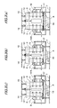
Figs. 3(a), 3(b) and 3(c) are front views showing a procedure of moving side walls in the first embodiment. -
Figs. 4(a) and 4(b) are partial sectional views showing a relation between a suction hopper and lower end portions of side walls at the time of moving the side walls in the first embodiment. -
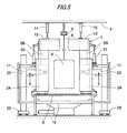
Fig. 5 is a front view showing a second embodiment of the powder coating apparatus of the present invention. -
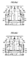
Figs. 6(a), 6(b) ,6(c) and 6(d) are front views showing a procedure of moving side walls and ceiling walls in the second embodiment. -
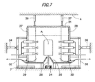
Fig. 7 is a front view showing a state in which side walls are expanded in a third embodiment of the powder coating apparatus of the present invention. -
Fig. 8 is a front view showing a state in which side walls are contracted in the third embodiment of the powder coating apparatus of the present invention. -
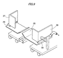
Fig. 9 is a perspective view showing a bottom face portion of the third embodiment of the powder coating apparatus of the present invention. -
Fig. 10 is a plan view showing a fourth embodiment of the powder coating apparatus of the present invention. - Exemplary embodiments of the present invention will be explained as follows.
-
Figs. 1 to 4 are views showing a first embodiment in which right andleft side walls coating booth 1 are respectively structured as movable walls capable of moving in a lateral direction which is perpendicular to a moving direction of a work A in thecoating booth 1. An inner width of thecoating booth 1 is changed according to a dimension of the work A to be coated passing in thecoating booth 1 so that an inner volume can be adjusted to the dimensions of the work A. - The right and
left side walls coating booth 1 are arranged on both sides of the work A which moves while being hung by ahanger 6 of aconveyer 5 arranged on aceiling 4 of a building. To front and rear of the right andleft side walls - The right and
left side walls rail 8 arranged on afloor 7 so that the right andleft side walls - As shown in
Fig. 1 , when a lateral width of the work A is large, the right andleft side walls coating booth 1 can be extended. On the contrary, as shown inFigs. 3(b), 3(c) , when the lateral width of the work A is small, the right andleft side wall coating booth 1 can be reduced. Thereby, the right andleft side wall - The right and
left side walls pistons side walls - In the first embodiment, three
coating guns 11 are respectively arranged on the right andleft side walls coating guns 11 move in the lateral direction together with the right and leftside walls coating gun 11 can be adjusted. - Above the right and left
side walls ceiling walls side wall ceiling walls ceiling walls ceiling 4 of the building through thepistons pistons Figs. 3 (a) and 3 (b) , theceiling walls side walls pistons ceiling walls side walls side walls ceiling walls - The reason why the
ceiling walls side walls ceiling walls side walls side walls ceiling walls side walls side walls pistons Figs. 3(a) and 3(b) , and theceiling walls side walls Fig. 3(c) , the rods of thepistons ceiling walls side walls side walls ceiling walls - On a floor face of the
coating booth 1, asuction hopper 16 for recovering over-sprayed coating material powder is arranged along the moving direction of the work A. It is preferable that a quantity of suction sucked by anover-sprayed powder collector 100 through thesuction hopper 16 is adjusted according to an inner volume of thecoating booth 1. When the right and leftside walls - The lateral width of an upper end portion of the
suction hopper 16 is the same as a width at which the right and leftside walls side walls suction hopper 16 and the lower end portions of the right and leftside walls Figs. 4(a), 4(b) , between both side portions of the upper end of thesuction hopper 16 and the lower end portions of the right and leftside walls side walls - As described above, although an inner height of the
coating booth 1 shown inFigs. 1 to 4 is constant, by moving the right and leftside walls coating booth 1 can be adjusted. - This adjustment of the inner width of the coating booth may be automatically made as follows. Before the work A arrives to the
coating booth 1, the lateral width of the work A is detected by a sensor. According to a result of a detection, the rods of thepistons ceiling walls pistons side walls side walls - In the first embodiment, a piston mechanism is used for a drive means for moving the right and left
side walls - The right and left
side walls ceiling walls -
Figs. 5 and6 are views showing a second embodiment. In the second embodiment, an inner volume of the coating booth is adapted to the dimensions of the works A by changing both the inner width and the inner height of thecoating booth 1.
In explanations of the second embodiment, parts in common with the first embodiment shown inFigs. 1 to 4 are indicated by the same reference numerals. - In the second embodiment, the moving mechanism of moving the right and left
side walls ceiling walls side walls ceiling walls coating booth 1 can be changed by elevating theceiling walls pistons side walls side walls lower walls upper walls upper walls lower walls pistons lower walls - In the second embodiment, the
coating guns 11 are arranged in thereciprocators 22 for moving thecoating guns 11 in a vertical direction. Thereciprocators 22 are arranged on apedestal 23 having wheels and can also move in the lateral direction. - In the second embodiment, the right and left
side walls ceiling walls -
Fig. 5 is a view showing a state in which the right and leftside walls ceiling walls coating booth 1 is maximized at the time of coating the largest work A. At the time of coating the small work A to be coated as shown inFigs. 6(a) to 6(d) , the state is changed from the above state in such a manner that the right and leftside walls ceiling walls - First, as shown in
Fig. 6(a) , theceiling walls side walls ceiling walls Fig. 6(b) , the rods of thepistons side walls ceiling walls Fig. 6(c) , theupper walls pistons lower walls side walls ceiling walls Fig. 6(d) . In this way, gaps formed between upper end portions of theupper walls ceiling walls - After that, as shown in
Fig. 6(d) , thereciprocators 22 are moved inward so that they can agree with the small work A and a distance between thecoating guns 11 and the small work A can be adjusted. -
Figs. 7 ,8 and9 are views showing a third embodiment in which the right and leftside walls coating booth 1 are structured as the movable walls capable of moving in the lateral direction in the same manner as that of the first embodiment. By moving the movable walls, the inner width of thecoating booth 1 is changed according to the dimension of the work A passing in thecoating booth 1. In this way, the inner volume of the coating booth is adapted to the dimension of the work A in the third embodiment. - In the first embodiment, the work A is hung by the
hanger 6. However, in the third embodiment, aconveyer 24 for conveying the work A is arranged on a floor face and asupport 26 for supporting the work A is moved in a central portion of thefloor face 25 of thecoating booth 1.Exhaust ducts side walls - The
side walls frames pistons exhaust ducts Fig. 7 is a view showing a state in which theside walls Fig. 8 is a view showing a state in which theside walls - In the third embodiment, the
ceiling walls 31 are supported being hung so that they can elevate bypistons -
Fig. 10 is a view showing the fourth embodiment in which theside walls coating booth 1 are divided into two portions, one is a first half portion and the other is a second half portion, in the moving direction of the work A. Theside walls pistons 41 with respect to theside walls - In the fourth embodiment, the work A is turned by 90° in a middle of movement in the moving direction and both sides of the work A are coated in the first half portion and both end faces of the work A are coated in the second half portion. In the first half portion of the
coating booth 1, the width of the work A is small. Therefore, theside walls side walls - In the fourth embodiment, the
coating guns 11 are respectively arranged in the first half portion and the second half portion of thecoating booth 1 being opposed to each other. - While description has been made in connection with specific embodiments and modified examples of the present invention, it will be obvious to those skilled in the art that various changes and modification may be made therein without departing from the present invention. It is aimed, therefore, to cover in the appended claims all such changes and modifications falling within the true spirit and scope of the present invention.
-
- 1
- Coating booth
- 2, 3
- Side wall
- 4
- Ceiling
- 5
- Conveyer
- 6
- Hanger
- 7
- Floor
- 8
- Rail
- 9, 10
- Piston
- 11
- Coating gun
- 12, 13
- Ceiling wall
- 14, 15
- Piston
- 16
- Suction hopper
- 17
- Cover
- 2A, 3A
- Lower wall
- 2B, 3B
- Upper wall
- 20, 21
- Piston
- 22
- Reciprocator
- 23
- Pedestal
- 24
- Conveyer
- 25
- Floor face
- 26
- Support
- 27, 28
- Side wall
- 29, 30
- Exhaust duct
- 31
- Ceiling wall
- 32, 33
- Frame having wheels
- 34, 35, 36, 37
- Piston
- 38A, 39A, 38B, 39B
- Side wall
Claims (10)
- A powder coating apparatus comprising:a coating booth (1), wherein a work (A) to be coated is moved by a conveyer (5, 24) in the coating booth (1) ; anda coating gun (11) that sprays powder coating material to the moving work (A),wherein the coating booth (A) includes a movable wall (2, 3, 12, 13, 27, 28, 38A, 39A) on at least one of a side wall (2, 3, 27, 28, 38, 39) and a ceiling wall (12, 13) of the coating booth (1), and
wherein the movable wall (2, 3, 12, 13, 27, 28, 38A, 39A) is configured to move in accordance with the work (A) passing the coating booth (1). - The powder coating apparatus according to claim 1, wherein the movable wall (2, 3, 27, 28, 38A, 39A) is provided on the side wall (2, 3, 27, 28, 38, 39), and an inner width of the coating booth (1) is changed in accordance with the work (A) passing the coating booth (1).
- The powder coating apparatus according to any of the preceding claims, wherein the side wall (38, 39) is divided into a first portion (38A, 39A) and a second portion (38B, 39B) in a moving direction of the work (A), and the movable wall (38A, 39A) is provided on one of the first portion and the second portion.
- The powder coating apparatus according to any of the preceding claims, wherein the movable wall (12, 13) is provided on the ceiling wall (12, 13) , and a ceiling height of the coating booth (1) is changed in accordance with the work (A) passing the coating booth (1).
- The powder coating apparatus according to any of the preceding claims, further comprising:an over-sprayed powder collector (100) connected to the coating booth (1), wherein the over-sprayed powder collector (100) is configured so that a volume of suction of the over-sprayed powder collector (100) is adjusted in accordance with an inner volume of the coating booth (1).
- A powder coating method comprising:moving a work (A) to be coated in a coating booth (1);spraying powder coating material to the work (A) by a coating gun (11) ; andmoving a movable wall (2, 3, 12, 13, 27, 28, 38A, 39A) on at least one of a side wall (2, 3, 27, 28, 38, 39) and a ceiling wall (12, 13) of the coating booth (1), in accordance with the work (A) passing the coating booth (1).
- The powder coating method according to any of the preceding claims, further comprising:changing an inner width of the coating booth (1) in accordance with the work (A) passing the coating booth (1), by moving the movable wall (2, 3, 27, 28, 38A, 39A) provided on the side wall (2, 3, 27, 28, 38, 39).
- The powder coating method according to any of the preceding claims, wherein the side wall (38, 39) is divided into a first portion (38A, 39A) and a second portion (38B, 39B) in a moving direction of the work (A), and the movable wall (38A, 39A) is provided on one of the first portion and the second portion.
- The powder coating method according to any of the preceding claims, further comprising:changing a ceiling height of the coating booth (1) in accordance with the work (A) passing the coating booth (1), by moving the movable wall (12, 13) provided on the ceiling wall (12, 13).
- The powder coating method according to any of the preceding claims, further comprising:adjusting a volume of suction of an over-sprayed powder collector (100) connected to the coating booth (1) in accordance with an inner volume of the coating booth (1).
Applications Claiming Priority (1)
| Application Number | Priority Date | Filing Date | Title |
|---|---|---|---|
| JP2007283692A JP4664344B2 (en) | 2007-10-31 | 2007-10-31 | Powder coating equipment |
Publications (2)
| Publication Number | Publication Date |
|---|---|
| EP2055393A1 true EP2055393A1 (en) | 2009-05-06 |
| EP2055393B1 EP2055393B1 (en) | 2011-03-16 |
Family
ID=39968057
Family Applications (1)
| Application Number | Title | Priority Date | Filing Date |
|---|---|---|---|
| EP08166214A Expired - Fee Related EP2055393B1 (en) | 2007-10-31 | 2008-10-09 | Powder coating apparatus and powder coating method |
Country Status (5)
| Country | Link |
|---|---|
| US (1) | US8113140B2 (en) |
| EP (1) | EP2055393B1 (en) |
| JP (1) | JP4664344B2 (en) |
| CN (1) | CN101422768B (en) |
| DE (1) | DE602008005534D1 (en) |
Cited By (1)
| Publication number | Priority date | Publication date | Assignee | Title |
|---|---|---|---|---|
| WO2012089789A1 (en) * | 2010-12-28 | 2012-07-05 | Trasmetal S.P.A. | Paint booth for painting plants for products |
Families Citing this family (13)
| Publication number | Priority date | Publication date | Assignee | Title |
|---|---|---|---|---|
| CN102198442B (en) * | 2011-05-31 | 2012-09-12 | 胜利油田胜利石油化工建设有限责任公司 | Mechanized bent pipe coating device |
| CN103056071A (en) * | 2013-02-04 | 2013-04-24 | 侯如升 | Spraying liquid recovering device for spraying equipment |
| DK177812B1 (en) * | 2013-03-06 | 2014-07-28 | Imbox Shoecare As | Apparatus as well as method for applying an impregnating agent onto surfaces of items, in particular footwear |
| US10226786B2 (en) | 2013-08-15 | 2019-03-12 | Gema Switzerland Gmbh | Powder pipe coating booth |
| CN104722438B (en) * | 2013-12-20 | 2017-07-11 | 北汽福田汽车股份有限公司 | For the device of vehicle spray painting |
| CN103920613B (en) * | 2014-03-26 | 2016-09-14 | 蚌埠市高德机械自动化科技有限公司 | A kind of fully automatic powder recycling powder spraying chamber device |
| CN106584284A (en) * | 2017-01-16 | 2017-04-26 | 成都兆丰斯诺科技有限公司 | Shot blasting derusting machine used for derusting bent pipe |
| CN107824363A (en) * | 2017-12-07 | 2018-03-23 | 天长市金陵电子有限责任公司 | A kind of powder recovery system of electrostatic spraying |
| JP6903304B2 (en) * | 2018-02-05 | 2021-07-14 | 旭サナック株式会社 | Painting equipment |
| CN110694840B (en) * | 2019-10-24 | 2020-06-19 | 杭州杭叉机械设备制造有限公司 | Spraying production line |
| CN113385325B (en) * | 2021-05-18 | 2022-10-28 | 湖南华成铁建新材料有限公司 | A corrosion-resistant new material spraying equipment for metal surface |
| CN114308483A (en) * | 2021-11-22 | 2022-04-12 | 浙江科鑫重工有限公司 | H-shaped steel powder spraying system |
| CN116532255A (en) * | 2023-05-06 | 2023-08-04 | 苏州东仪核电科技股份有限公司 | A spraying device and spraying method for on-site cabinets |
Citations (4)
| Publication number | Priority date | Publication date | Assignee | Title |
|---|---|---|---|---|
| DE3640699A1 (en) | 1986-11-28 | 1988-06-09 | Gema Ransburg Ag | Booth for spray coating articles |
| US4932316A (en) | 1989-04-26 | 1990-06-12 | Flakt, Inc. | Paint spray booth with movable inner walls |
| US5421885A (en) | 1992-11-20 | 1995-06-06 | Trevisan; Ferdinando | Powdered-paint spraying plant with variable-section booth |
| JP2004167366A (en) * | 2002-11-20 | 2004-06-17 | Kanto Auto Works Ltd | Air feed port adjustment structure for coating booth |
Family Cites Families (8)
| Publication number | Priority date | Publication date | Assignee | Title |
|---|---|---|---|---|
| IT1202010B (en) * | 1985-07-29 | 1989-02-02 | Ferdinando Trevisan | PAINTING BOOTH FOR THE APPLICATION OF SURFACE COATINGS STARTING FROM POWDER PRODUCTS |
| JPH0685898B2 (en) * | 1987-01-26 | 1994-11-02 | 東洋ラジエ−タ−株式会社 | Coating equipment |
| DE3743864A1 (en) * | 1987-12-23 | 1989-07-06 | Praezisions Werkzeuge Ag | METHOD FOR REDUCING ENVIRONMENTAL INFLUENCES ON THE POWDER COATING OF A WORKPIECE AND POWDER COATING SYSTEM |
| US5259879A (en) * | 1991-06-27 | 1993-11-09 | Ransburg Corporation | Powder application booth liner and method of making it |
| JPH06320079A (en) * | 1993-05-18 | 1994-11-22 | Toyota Motor Corp | painting booth |
| US5906676A (en) * | 1997-10-01 | 1999-05-25 | Nordson Corporation | Ejector-augmented overspray reclaim system |
| JP2000093860A (en) * | 1998-09-22 | 2000-04-04 | Nissan Motor Co Ltd | painting booth |
| DE202004021737U1 (en) * | 2003-07-18 | 2010-08-26 | Abb As | Inking system |
-
2007
- 2007-10-31 JP JP2007283692A patent/JP4664344B2/en not_active Expired - Fee Related
-
2008
- 2008-10-09 EP EP08166214A patent/EP2055393B1/en not_active Expired - Fee Related
- 2008-10-09 DE DE602008005534T patent/DE602008005534D1/en active Active
- 2008-10-14 US US12/251,134 patent/US8113140B2/en not_active Expired - Fee Related
- 2008-10-28 CN CN2008101746038A patent/CN101422768B/en not_active Expired - Fee Related
Patent Citations (4)
| Publication number | Priority date | Publication date | Assignee | Title |
|---|---|---|---|---|
| DE3640699A1 (en) | 1986-11-28 | 1988-06-09 | Gema Ransburg Ag | Booth for spray coating articles |
| US4932316A (en) | 1989-04-26 | 1990-06-12 | Flakt, Inc. | Paint spray booth with movable inner walls |
| US5421885A (en) | 1992-11-20 | 1995-06-06 | Trevisan; Ferdinando | Powdered-paint spraying plant with variable-section booth |
| JP2004167366A (en) * | 2002-11-20 | 2004-06-17 | Kanto Auto Works Ltd | Air feed port adjustment structure for coating booth |
Cited By (1)
| Publication number | Priority date | Publication date | Assignee | Title |
|---|---|---|---|---|
| WO2012089789A1 (en) * | 2010-12-28 | 2012-07-05 | Trasmetal S.P.A. | Paint booth for painting plants for products |
Also Published As
| Publication number | Publication date |
|---|---|
| DE602008005534D1 (en) | 2011-04-28 |
| JP4664344B2 (en) | 2011-04-06 |
| CN101422768B (en) | 2012-08-08 |
| JP2009106892A (en) | 2009-05-21 |
| CN101422768A (en) | 2009-05-06 |
| US8113140B2 (en) | 2012-02-14 |
| US20090110816A1 (en) | 2009-04-30 |
| EP2055393B1 (en) | 2011-03-16 |
Similar Documents
| Publication | Publication Date | Title |
|---|---|---|
| US8113140B2 (en) | Powder coating apparatus and powder coating method | |
| KR102114589B1 (en) | Powder Coating System | |
| KR100900565B1 (en) | Paint fugitive suction | |
| CN1894046A (en) | Spray coating device | |
| JP2015506275A (en) | Powder spray booth overspray collector | |
| KR19980087006A (en) | Device for separating excess sprayed excess powder during workpiece powder coating | |
| CN106925456A (en) | A kind of electrostatic powder coating machine | |
| KR100361416B1 (en) | Work Spray Coating Device | |
| JP2005525237A (en) | Powder coating spray booth with powder extraction system | |
| US5527564A (en) | Method and apparatus for repelling overspray in spray paint booths | |
| WO2012089787A1 (en) | Paint booth for painting plants for products | |
| JP7586423B2 (en) | Injection device | |
| KR102229154B1 (en) | Guide roller for enhancing wear-resistance and reciprocator for coating therewith | |
| CN210002810U (en) | Lifting assembly and spraying robot | |
| CN209791844U (en) | Edge gas isolation device, powder spraying equipment and powder spraying production line | |
| KR20220102393A (en) | Foldable robot painting device | |
| ITMI20080963A1 (en) | PAINTING CABIN WITH DUST BLASTING SYSTEM | |
| CN209452152U (en) | The environmental control system of paint spraying machine reciprocating drive mechanism | |
| JP2012143664A (en) | Powder coating device | |
| CN112570177A (en) | Paint spraying apparatus that reliability is high | |
| KR102752354B1 (en) | Multi-directional paint spray system | |
| CN111940179A (en) | A flexible robot spraying system | |
| CN221086094U (en) | Powder spraying room | |
| CN116422515B (en) | Multi-angle paint spraying apparatus with drying mechanism for metal support | |
| CN223996376U (en) | A blister tray spraying equipment |
Legal Events
| Date | Code | Title | Description |
|---|---|---|---|
| PUAI | Public reference made under article 153(3) epc to a published international application that has entered the european phase |
Free format text: ORIGINAL CODE: 0009012 |
|
| 17P | Request for examination filed |
Effective date: 20081009 |
|
| AK | Designated contracting states |
Kind code of ref document: A1 Designated state(s): AT BE BG CH CY CZ DE DK EE ES FI FR GB GR HR HU IE IS IT LI LT LU LV MC MT NL NO PL PT RO SE SI SK TR |
|
| AX | Request for extension of the european patent |
Extension state: AL BA MK RS |
|
| 17Q | First examination report despatched |
Effective date: 20090610 |
|
| AKX | Designation fees paid |
Designated state(s): DE GB |
|
| GRAP | Despatch of communication of intention to grant a patent |
Free format text: ORIGINAL CODE: EPIDOSNIGR1 |
|
| RIN1 | Information on inventor provided before grant (corrected) |
Inventor name: KAIJU, HARUHISA C/O ASAHI SUNAC CORPORATION Inventor name: YAMAGUCHI, MASAYUKI |
|
| GRAS | Grant fee paid |
Free format text: ORIGINAL CODE: EPIDOSNIGR3 |
|
| GRAA | (expected) grant |
Free format text: ORIGINAL CODE: 0009210 |
|
| AK | Designated contracting states |
Kind code of ref document: B1 Designated state(s): DE GB |
|
| REG | Reference to a national code |
Ref country code: GB Ref legal event code: FG4D |
|
| REF | Corresponds to: |
Ref document number: 602008005534 Country of ref document: DE Date of ref document: 20110428 Kind code of ref document: P |
|
| REG | Reference to a national code |
Ref country code: DE Ref legal event code: R096 Ref document number: 602008005534 Country of ref document: DE Effective date: 20110428 |
|
| PLBE | No opposition filed within time limit |
Free format text: ORIGINAL CODE: 0009261 |
|
| STAA | Information on the status of an ep patent application or granted ep patent |
Free format text: STATUS: NO OPPOSITION FILED WITHIN TIME LIMIT |
|
| 26N | No opposition filed |
Effective date: 20111219 |
|
| REG | Reference to a national code |
Ref country code: DE Ref legal event code: R097 Ref document number: 602008005534 Country of ref document: DE Effective date: 20111219 |
|
| GBPC | Gb: european patent ceased through non-payment of renewal fee |
Effective date: 20121009 |
|
| PG25 | Lapsed in a contracting state [announced via postgrant information from national office to epo] |
Ref country code: GB Free format text: LAPSE BECAUSE OF NON-PAYMENT OF DUE FEES Effective date: 20121009 Ref country code: DE Free format text: LAPSE BECAUSE OF NON-PAYMENT OF DUE FEES Effective date: 20130501 |
|
| REG | Reference to a national code |
Ref country code: DE Ref legal event code: R119 Ref document number: 602008005534 Country of ref document: DE Effective date: 20130501 |