EP2055289A1 - Mechanism for massaging the lower parts of a user's legs - Google Patents
Mechanism for massaging the lower parts of a user's legs Download PDFInfo
- Publication number
- EP2055289A1 EP2055289A1 EP07704729A EP07704729A EP2055289A1 EP 2055289 A1 EP2055289 A1 EP 2055289A1 EP 07704729 A EP07704729 A EP 07704729A EP 07704729 A EP07704729 A EP 07704729A EP 2055289 A1 EP2055289 A1 EP 2055289A1
- Authority
- EP
- European Patent Office
- Prior art keywords
- discs
- mechanism according
- massage
- additional
- revolving shaft
- Prior art date
- Legal status (The legal status is an assumption and is not a legal conclusion. Google has not performed a legal analysis and makes no representation as to the accuracy of the status listed.)
- Granted
Links
- 230000007246 mechanism Effects 0.000 title claims abstract description 126
- 230000000295 complement effect Effects 0.000 claims description 8
- 238000000926 separation method Methods 0.000 claims description 5
- 238000000034 method Methods 0.000 claims description 4
- 230000008569 process Effects 0.000 claims description 2
- 230000001105 regulatory effect Effects 0.000 abstract description 2
- 238000004898 kneading Methods 0.000 description 9
- 230000009471 action Effects 0.000 description 6
- 230000000694 effects Effects 0.000 description 5
- 244000309466 calf Species 0.000 description 3
- 230000008859 change Effects 0.000 description 3
- 210000003205 muscle Anatomy 0.000 description 3
- 230000004913 activation Effects 0.000 description 2
- 239000003638 chemical reducing agent Substances 0.000 description 2
- 210000002979 radial nerve Anatomy 0.000 description 2
- 230000003213 activating effect Effects 0.000 description 1
- 230000006978 adaptation Effects 0.000 description 1
- 230000008901 benefit Effects 0.000 description 1
- 230000001419 dependent effect Effects 0.000 description 1
- 210000005036 nerve Anatomy 0.000 description 1
- 230000002093 peripheral effect Effects 0.000 description 1
- 230000000630 rising effect Effects 0.000 description 1
- 238000010079 rubber tapping Methods 0.000 description 1
- 230000035807 sensation Effects 0.000 description 1
Images









Classifications
-
- A—HUMAN NECESSITIES
- A61—MEDICAL OR VETERINARY SCIENCE; HYGIENE
- A61H—PHYSICAL THERAPY APPARATUS, e.g. DEVICES FOR LOCATING OR STIMULATING REFLEX POINTS IN THE BODY; ARTIFICIAL RESPIRATION; MASSAGE; BATHING DEVICES FOR SPECIAL THERAPEUTIC OR HYGIENIC PURPOSES OR SPECIFIC PARTS OF THE BODY
- A61H15/00—Massage by means of rollers, balls, e.g. inflatable, chains, or roller chains
- A61H15/0078—Massage by means of rollers, balls, e.g. inflatable, chains, or roller chains power-driven
-
- A—HUMAN NECESSITIES
- A61—MEDICAL OR VETERINARY SCIENCE; HYGIENE
- A61H—PHYSICAL THERAPY APPARATUS, e.g. DEVICES FOR LOCATING OR STIMULATING REFLEX POINTS IN THE BODY; ARTIFICIAL RESPIRATION; MASSAGE; BATHING DEVICES FOR SPECIAL THERAPEUTIC OR HYGIENIC PURPOSES OR SPECIFIC PARTS OF THE BODY
- A61H15/00—Massage by means of rollers, balls, e.g. inflatable, chains, or roller chains
- A61H2015/0007—Massage by means of rollers, balls, e.g. inflatable, chains, or roller chains with balls or rollers rotating about their own axis
- A61H2015/0028—Massage by means of rollers, balls, e.g. inflatable, chains, or roller chains with balls or rollers rotating about their own axis disc-like, i.e. diameter substantially greater than width
- A61H2015/0035—Massage by means of rollers, balls, e.g. inflatable, chains, or roller chains with balls or rollers rotating about their own axis disc-like, i.e. diameter substantially greater than width multiple on the same axis
-
- A—HUMAN NECESSITIES
- A61—MEDICAL OR VETERINARY SCIENCE; HYGIENE
- A61H—PHYSICAL THERAPY APPARATUS, e.g. DEVICES FOR LOCATING OR STIMULATING REFLEX POINTS IN THE BODY; ARTIFICIAL RESPIRATION; MASSAGE; BATHING DEVICES FOR SPECIAL THERAPEUTIC OR HYGIENIC PURPOSES OR SPECIFIC PARTS OF THE BODY
- A61H23/00—Percussion or vibration massage, e.g. using supersonic vibration; Suction-vibration massage; Massage with moving diaphragms
- A61H23/02—Percussion or vibration massage, e.g. using supersonic vibration; Suction-vibration massage; Massage with moving diaphragms with electric or magnetic drive
-
- A—HUMAN NECESSITIES
- A61—MEDICAL OR VETERINARY SCIENCE; HYGIENE
- A61H—PHYSICAL THERAPY APPARATUS, e.g. DEVICES FOR LOCATING OR STIMULATING REFLEX POINTS IN THE BODY; ARTIFICIAL RESPIRATION; MASSAGE; BATHING DEVICES FOR SPECIAL THERAPEUTIC OR HYGIENIC PURPOSES OR SPECIFIC PARTS OF THE BODY
- A61H7/00—Devices for suction-kneading massage; Devices for massaging the skin by rubbing or brushing not otherwise provided for
- A61H7/007—Kneading
Definitions
- This invention belongs to the technical field of the automatic massage mechanisms, and more specifically to the sector of the automatic mechanisms for massaging the lower part of users' legs.
- mechanisms are usually used with a first pair of revolving massage discs connected permanently and eccentrically to a first revolving shaft, separated in order to give massages on opposite sides of the lower part of the user's first leg, the revolving discs of the first pair of discs in the first rotation planes being inclined with respect to the first revolving shaft, and a second pair of revolving massage discs fixed together and eccentrically to a second revolving shaft, separated to give massages on opposite sides of the lower part of a second user leg, the revolving discs of the second pair of discs in the second rotation planes being inclined with respect to the second revolving shaft.
- the revolving axes are connected to an activation mechanism capable of turning the revolving axes in the first direction, and in a second direction opposite to the first.
- Mechanisms of this kind are described, for example, in the application for Japanese patent SHO-59-28963 , in the application for Japanese patent HEI 4-78307 and in the application for Japanese patent HEI 2-109628 .
- This kind of mechanisms though enabling efficient massage,have the drawback of giving a single type of kneading massage given simultaneously and equally on both of the user's legs, which means they give users very little variation.
- European patent EP-A-1000600 describes a mechanism which enables different types of massage to be given to the lower part of a user's legs by means of a massage mechanism that includes a revolving shaft, a pair of right and left massage rollers mounted on an intermediate part of the revolving shaft in an inclined manner, with respect to a geometric axis of the revolving shaft, means of actuation to turn the revolving shaft and switching means to change the position of the right and left massage rollers to a kneading position in which the massage rollers are inclined opposite each other, and a non-kneading position in which the massage rollers are inclined parallel to each other.
- this mechanism allows kneading and non-kneading massages to be given to the user's legs, it has the drawback that this is achieved by means of a relatively complicated mechanism for each of the user's legs.
- the massaging elements are constituted by pairs of long plates set out on inclined planes with respect to the revolving shaft, so that they move while changing the degree of information with respect to the length of the part to be massaged. Furthermore, between the long plates an intermediate element is planned which is constituted by a base, one end of which is fixed to a spring and also leans on a cam provided on the revolving shaft.
- the intermediate massage element used has the drawback that from a horizontal position, the rising movement causes a lateral variation in the massage area, but not on the rear part of the leg, and fails to achieve the desired effect, for the movement made has an effect substantially different from that caused by a masseur, which is a drawback.
- This invention is intended to overcome the drawbacks of the mechanisms of the state of the technique, by means of a mechanism which, while conventional, includes a first pair of massage discs supported eccentrically on a first revolving shaft, separated to give massages on opposite sides of the lower part of the user's first leg, the discs of the first pair of discs being set out on first inclined planes with respect to the first revolving shaft, and the second pair of massage discs supported eccentrically on a second revolving shaft, separated to give massages on opposite sides of the lower leg of the user's second leg, the discs of the second pair of discs being set out on second inclined planes with respect to the second revolving shaft, and in which the revolving shafts are connected to an activation mechanism capable of rotating the said revolving shafts in a first direction, and in the second opposite direction to the first, the mechanism of which, according to the invention, also includes at least one clutch mechanism with at least one internal housing, which includes a first stop element and a second stop element,
- the discs of each pair of discs are revolving, so they are fixed to the shaft, or may also be fixed to the shaft by means of an eccentric and connected to a fixed point to prevent their turning.
- This layout of elements means that, depending on the rotation direction of the revolving shafts, the discs of the first pair of massage discs of the first revolving shaft and the discs of the second pair of discs of the second revolving shaft are in identical positions, or in dysphase and even inverted positions.
- the pairs of massage discs may perform a kneading massage on the same part of each of the user's legs or at different heights of the respective leg, in other words, in one turn of the shafts, massaging a higher part of the first leg by means of the first pair of discs and massaging the other leg at a lower part, using the second pair of discs, and performing the respective massages in inverted positions on the following turn of the revolving shafts.
- the clutch mechanism is attached to the first end of the first revolving shaft, whereas in a second version of the invention, the clutch mechanism allows the first end of the first revolving shaft in the arched section passage to turn.
- the clutch mechanism may be set out between the first revolving shaft, and the first end of the second revolving shaft, the first end of the second revolving shaft then being coupled in the housing.
- the activating mechanism may be connected to a second end of one of the revolving shafts.
- the arched vertical section passage may extend in an arc of between 40 and 270°, particularly between 160 and 200°, preferably between 170 and 190° and more preferably of approximately 180°.
- the clutch mechanism may include a clutch housing that has an internal cavity with an intermediate cavity connected to a first cylindrical lateral passage, a second cylindrical lateral passage, and an access passage to the intermediate cavity between the cylindrical lateral passages; a first bushing housed revolvingly in the first lateral passage, and a second bushing housed revolvingly in the second lateral passage, each bushing emerging into the intermediate cavity at one of their ends.
- the first end of the first revolving shaft is coupled to the first bushing and the first end of the second revolving shaft is coupled to the second bushing, whereas the internal housing for the first end of the second revolving shaft is formed inside the second bushing.
- the ends of the bushings which emerge into the intermediate cavity may both have gearing means which mesh with complementary actuation means, such as a helicoidal actuation shaft, which enters through the access passage into the intermediate cavity of the clutch housing, or a gearwheel, which meshes with the gearing means of each bushing.
- complementary actuation means such as a helicoidal actuation shaft, which enters through the access passage into the intermediate cavity of the clutch housing, or a gearwheel, which meshes with the gearing means of each bushing.
- the first shaft When the first end of the first shaft can turn inside the clutch mechanism, it may include an additional internal housing, which has a first additional stop element and a second additional stop element, an additional arched vertical section passage between the additional stop elements, and an additional protrusion between the additional stops. This additional protrusion comes into contact with one or the other of the additional stop elements depending on the turning direction of the revolving shafts, so that the first end of the first 1 revolving shaft is coupled in the additional housing of the clutch mechanism.
- an additional internal housing which has a first additional stop element and a second additional stop element, an additional arched vertical section passage between the additional stop elements, and an additional protrusion between the additional stops. This additional protrusion comes into contact with one or the other of the additional stop elements depending on the turning direction of the revolving shafts, so that the first end of the first 1 revolving shaft is coupled in the additional housing of the clutch mechanism.
- the additional passage and the additional stop elements are also set out on a plane perpendicular to the longitudinal axis of the revolving shafts, the additional passage being an entering element selected between an additional exterior entering element formed on a first end of the external perimeter of the first revolving shaft and an additional interior entering element in an internal wall of the additional housing in which the first end of the first revolving shaft is coupled.
- the additional stop elements and the additional protrusion are set out in such a way that the additional protrusion comes into contact with one of the additional stop elements when the revolving shafts turn in the first action, and comes into contact with the other additional stop element when the revolving shafts turn in the second opposite direction.
- the additional protrusion may be an additional interior protrusion which emerges from the internal perimeter of the additional housing, or an additional external protrusion which emerges from the external perimeter of the first end of the first shaft.
- the additional internal housing for the first end of the first revolving shaft may be formed inside the first revolving bushing.
- the arched vertical section passage and the arched vertical section additional passage may together have an arc extension of between 40 and 270°, particularly between 160 and 200°, preferably between 170 and 190°, and more preferably 180°.
- the inclusion is planned of an intermediate massage element located between the discs of each pair of discs to achieve a more complete massage.
- the intermediate massage element is expected to include at least one body not perpendicular to the revolving shaft during the massage process and which is activated by making a transversal movement on the rear part of the surface to be massaged.
- This setup has the great advantage that the massage surface of the intermediate massage element provides a transversal movement similar to that provided by a masseur of the type known as "kneading", unlike the intermediate massage element described in the document of Japanese patent JP 2003-665 , in which the said intermediate massage element causes a rising-falling movement on the leg so that the massaged surface is varied by the long plates and so that the said intermediate massage element causes gentle "tapping" on the lower part of the leg which has nothing to do with the "kneading" massage provided by the current invention.
- the intermediate massage element includes a body lying on the revolving shaft, with a massage surface longitudinal with respect to the rear part of the surface to be massaged, on which the transversal movement roughly defines an "eight".
- the intermediate massage element is connected to a fixed point by means of at least a first elastic element, to avoid the said intermediate massage element turning when activated, keeping the massage surface in contact with the surface to be massaged.
- the intermediate massage element is supported on one of the discs of a pair of discs instead of on the revolving shaft, as occurred in the previous version.
- the intermediate massage element may be constituted by a lateral extension connected to one of the discs of the pair of discs, or, on the other hand, the latter extension may be supported on one of the discs of the pair of discs by means of a shaft which allows it to turn.
- the discs of each pair of discs are connected to a fixed point, by means of at least a second elastic element to prevent it from turning with the angular movement of the revolving shaft, and to keep the massage surface of the intermediate massage element in contact with the part to be massaged.
- the invention plans for the said intermediate massage element to include a body with a massage surface that is stretched and longitudinal with respect to the surface to be massaged, and of the type described when the intermediate massage element is supported on the revolving shaft.
- the intermediate massage element might include a long body inclined towards the revolving shaft, with a massage surface corresponding to one of its ends.
- the long inclined body directed towards the revolving shaft stops at a pivot connected to one of discs. This stop is planned to use the third elastic element to keep the long body in contact with the said stop.
- each of the discs which constitute the pair of discs should include a lateral extension connected to the said discs, so that these extensions might be identical or different depending on the different types of extensions described before.
- the intermediate massage element includes a long element inclined towards the revolving shaft, the movement made by the long body is approximately circular.
- the massage surface of the intermediate massage element is at least semi cylindrical in all the previous versions.
- Another possible version of the invention provides for the intermediate massage element to be determined by a plate, which includes means of vibration to apply a vibrating movement and give a massage of such characteristics to the user's leg.
- the plate is fixed to the chassis of the mechanism or on one or both discs of each pair of discs.
- the plate is fixed to the chassis and one of its ends, leaving the other end free to facilitate the vibration.
- the means of vibration include a motor with two opposite shafts provided with a counterweight at the ends, also the motor lying in a housing fixed to the lower side of the plate, so that when it is activated, the motor causes the vibration thereto.
- the invention includes means for regulating the separation between the discs of the pairs of discs, means which allow the axial movement of at least one of the said discs of each pair of discs on the revolving shaft.
- These means are preferably constituted by a fourth elastic element, which keeps at least one of the discs of each pair of discs pressed against a stop, so that at least one of the discs of each pair of discs moves to overcome the action of the fourth elastic element, when a massage surface is located with larger dimensions than the separation planned between the discs of each pair of discs.
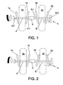
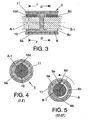
- Figures 1 and 2 show a first version of the massage mechanism according to the present invention, which includes a first pair of massage discs 1a, 1b, which on revolving discs and connected permanently and eccentrically to a first revolving shaft A, separated to massage opposite sides of the lower part of the user's first leg 3a, and a second pair of massage discs 2a, 2b, which are also revolving discs and are connected permanently and eccentrically to a second revolving shaft B, separated to massage opposite sides of the lower part of the user's second leg 3b.
- a first pair of massage discs 1a, 1b which on revolving discs and connected permanently and eccentrically to a first revolving shaft A, separated to massage opposite sides of the lower part of the user's first leg 3a
- a second pair of massage discs 2a, 2b which are also revolving discs and are connected permanently and eccentrically to a second revolving shaft B, separated to massage opposite sides of the lower part of the user'
- the revolving discs 1a, 1b of the first pair of discs are set out in first rotation inclined planes with respect to the first revolving shaft A, whereas the revolving discs 2a, 2b of the second pair of discs are set out in second rotation inclined planes with respect to the second revolving shaft B.
- Revolving shafts A, B are connected by their respective first ends A-1, B-1 to a clutch mechanism which connects the said shafts A, B together.
- the first shaft A is connected by its second end A-2 to a bearing, whereas the second end B-2 of the second shaft is connected conventionally to a conventional actuation mechanism 4, such as an electric motor with reducer unit, capable of giving rotating shafts A, B an anticlockwise rotation ( fig. 1 ) and a clockwise rotation ( fig.2 ).
- the clutch mechanism connects shafts A, B so that when the shafts turn anticlockwise, as shown in figure 1 , the pairs of massage discs 1a, 1b; 2a, 2b are aligned on their respective shafts A, B in identical inclined positions, so that they simultaneously press and release the same part of the user's legs 3a, 3b, whereas, when shafts A, B turn clockwise ( fig. 2 ), the clutch mechanism causes a dysphase in the first shaft A with regard to its turning approximately 180° with regard to the second shaft B.
- the second rotating discs 2a, 2b take up positions in which their inclinations with respect to the second revolving shaft B are exactly opposite to the inclinations of the first massage discs 1a, 1b so that when the first massage discs 1a, 1b press a first part and release another part of the user's first leg 3a, the second massage discs 2a, 2b release the corresponding first part of the second leg 3b and press the corresponding second part of this second leg 3b.
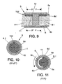
- FIGs 3 to 8 show a first version of a clutch mechanism 5 which can be included in the massage mechanism of figures 1 and 2 .
- This mechanism 5 includes a body 5a with a housing 10 to which end A-1 of the first revolving shaft A is connected, and another housing 6, formed in axial alignment with housing 10, to which the second revolving shaft B is connected.
- Body 5a is housed in an exterior bushing 11.
- the internal housing 6 includes a first stop element 6a and a second stop element 6b, a vertical section passage 6c arched between stop elements 6a, 6b, and a protrusion 6d in the form of an axial nerve, which moves through the said passage 6c between stops 6a, 6b depending on the turning direction of shafts A, B.
- the passage 6c and the stop elements 6a, 6b are set out on a plane perpendicular to the longitudinal axis of the revolving shafts A, B.
- the passage 6c is formed by an interior insert in a part of an internal wall of housing 6 to which end B-1 of the second revolving shaft B is connected and moves in the interior insert or passage 6c.
- the housing 10 includes an insert in which a protrusion 10d is housed, which emerges from periphery of the first end A-1 of the first shaft A, so that the first shaft A is immobilised in the body 5a of the clutch mechanism 5.
- Figures 3 to 5 show the layout of insert 6d in passage 6c when shafts A, B turn anticlockwise, that is, in the position corresponding to figure 1 .
- the protrusion 6d comes up against the first stop element 6a when shafts A, B turn, and the respective massage discs 1a, 1b; 2a, 2b lie in the position shown in figure 1 .
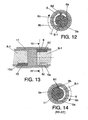
- step 6c is an exterior insert formed on the external perimeter of end B-1 of the second revolving shaft B and protrusion 6d is an interior protrusion that emerges from the internal perimeter of housing 6, and the first shaft A is immobilised in body 5a of the clutch mechanism 5 by means of a protrusion that emerges from the interior wall of housing 10 which fits in a complementary insert in the first end A-1 of the first shaft A.
- the protrusion 6d stops against the first stop element 6a as shown in figures 9 to 11 .
- the actuation mechanism 4 is in contact with clutch mechanism 5, and in the remainder the operation of this mechanism is similar to that of the version of the mechanism in figures 1 and 2 .
- FIGs 17 to 20 show a version of clutch mechanism 5 that can be included in the massage mechanism in figures 15 and 16 .
- the clutch mechanism 5 includes a clutch body 5a with an internal cavity 5b which includes an intermediate cavity 5c which is connected to a first cylindrical lateral passage 5d, with a second cylindrical lateral passage 5e, and with an access passage 5f to the intermediate cavity 5c.
- the access passage 5f is between the said cylindrical lateral passages 5d, 5e.
- a first bushing 7 is housed revolving, in which the first end A-1 of the first revolving shaft A is inserted.
- a second bushing 8 is housed revolving, in which the first end B-1 of the second revolving shaft B is housed.
- Bushings 7, 8 enter intermediate cavity 5c through one of the ends. These ends are both provided with peripheral tabs 7b, 8b and gearings 7a, 8a which mesh with a gearwheel 9 connected by means of a drive shaft 9a to the actuation mechanism 4 which might be, for instance, an electric motor unit with reducer if it is conventional.
- the shaft 9a enters the intermediate cavity 5c through the access passage 5f.
- an internal housing 10 is formed in which the first end A-1 of the revolving shaft A is immobilised by means of a protrusion 10 in the form of a radial nerve, which emerges from the said first end A-1 and fits in a complementary insert in the interior wall of housing 10.
- the internal housing 6 includes a first stop element 6a and a second stop element 6b, a passage 6c with a vertical cross section arched some 180° between the stop elements 6a, 6b and a protrusion 6d in the form of a radial nerve between the stops 6a, 6b totally dependent on the turning direction of shafts A, B.
- passage 6c and the stop elements 6a, 6b are set out on a plane perpendicular to the longitudinal shaft of the revolving shafts A, B.
- the passage 6c is formed by an interior insert in part of an internal wall of the housing 6, whereas the protrusion 6d emerges from the external perimeter of the said first end B-1 and moves in the interior insert 6c.
- the operation of the clutch mechanism shown in figures 17 to 20 is the same as that of the clutch mechanism in figures 3 to 8 , except that the actuation mechanisms 4 are not directly connected to one of the revolving shafts A, B, but turn some bushings 7, 8 which in turn drag the revolving shafts A, B in their revolving movement. Therefore, when the bushings 7, 8 turn clockwise, the stop element 6b in the housing 6 comes into contact with the radial protrusion 6d which emerges from the first part B-1 of the second revolving shaft B so that this shaft B turns along with the bushing 8 in the same direction, leaving the massage discs 1a, 1b; 2a, 2b in the positions shown in figure 15 .
- Figures 20 to 23 show another version of a clutch mechanism 5 which may be included in the massage mechanism in figures 15 and 16 .
- This version is different from the version in figures 17 to 20 in that the passage 6c stretches 90° instead of 180° in the internal wall of the housing 6 of the second bushing 8, and in which the internal housing 10 in the first bushing has the same configuration as the internal housing 6 in the second bushing 8. Therefore, the additional internal housing 10 includes a first additional stop element 10a and a second additional stop element 10b, an additional passage 10c with an arched vertical section with an extension of approximately 90° between the said additional stop elements 10a, 10b, and an additional protrusion 10d between the said additional stops 10a, 10b depending on the turning direction of the revolving shafts A, B.
- the additional passage 10c and the additional stop elements 10a, 10b are laid out in a plane perpendicular to the longitudinal axis of revolving shafts A, B, the additional passage 10c being an internal insert in an internal wall of the additional housing 10 in which the said first end A-1 of the first revolving shaft A is coupled, whereas the additional protrusion 10d emerges from the external perimeter of the first end A-1 of the first revolving shaft A.
- the mechanism is supported on a chassis 12 in which it is fixed, allowing the first revolving shaft A, and the second revolving shaft B. to turn by means of a motor 4.
- the disc pairs 1a, 1b; 2a, 2b are mounted by means of an eccentric 14 so that they are supported on a plane inclined longitudinally towards opposite ends and are moved by changing the information with respect to the length of the leg, which is located on the discs 1a, 1b; 2a, 2b for massaging.
- the different intermediate massage elements may be located indistinctly between the first discs 1a, 1b or between the second discs 2a, 2b and be the same or different.
- an intermediate massage element which is also mounted by means of an eccentric 14 on the second revolving shaft B, and which equally changes the inclination with respect to the length of the leg 3b, and which is finished off at the top by means of a cylindrical surface 16 on which the user's leg 3b is supported longitudinally, so that when the revolving shaft B is activated, a transversal movement is caused on the cylindrical surface 16 with respect to the length of the leg 3b defining roughly a figure "eight", which causes a massage sensation very similar to the "kneading" provided by a masseur.
- the intermediate element 15 is fixed to the chassis, by means of a first elastic element constituted by the first spring 24. In this way, when the revolving shaft B turns, the intermediate massage element 15 is prevented from turning, to give the required effect.
- each of the discs 1a, 1b supports an intermediate massage element. Therefore, on one of the discs 1b, it includes a natural extension provided with a first body 18 which includes a cylindrical stretched body 19 inclined towards the first revolving shaft A.
- a lateral extension which includes a second body 21 with a semi cylindrical stretched body 22 inclined towards shaft A.
- the discs 1a, 1b must not turn with shaft A, so they are fixed to the chassis 12 by means of two opposed second springs 17 which prevent discs 1a, 1b from turning and the first body 18 and the second body 21 remain in the required position.
- these bodies 18 and 21 are also fixed by means of a third spring 23 to each of the discs 1a, 1b and these complementarily have a pivot 25 against which the bodies 18 and 21 stop, which, through the action of the third spring 23 are kept in contact with the said pivots 25, to keep them in the massage position and not allow them to turn on shaft 20.
- the body 18 includes a cylindrical stretched body 19 and the body 21 a semi cylindrical stretched body 22, on which the leg to be massaged rests.
- This setup determines that when revolving shaft A turns and movement is caused in discs 1a, 1b in which they modify their inclination with respect to the first revolving shaft A, sequentially approaching and moving away from each other due to their layout on the eccentric 14, the same movement is caused in bodies 19 and 22 the massage surfaces of which perform a transversal circular movement on the rear part of the leg, and in the space between the discs 1a, 1b, improving the massage effect, as shown in figures 27 to 30 .
- the bodies 18 and 21 In the movement of the discs 1a, 1b, the bodies 18 and 21 must not touch each other but must remain at a safe distance between them to avoid pinching in the massaged area. In this way, the required massage is caused as described.
- the dimensions of the bodies 18 and 21 and the pivots 25 help to maintain this safety distance.
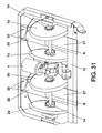
- the intermediate massage element is constituted by a plate 27 in which the lower face includes a housing 30 on which a motor 28 has been fixed, provided with two opposed shafts 29 the end of which have been fixed with counterweights 31, so that the actuation of the motor 28 causes a vibrating movement in the plate 27, which is fixed by one of its ends with bolts 32 to the chassis 12 to enable its vibration, so that when the rear part of the leg is placed on the plate, this transmits the vibration to the leg, giving it a vibrating massage.
- the invention also plans for the massaged area to be of different volumes, as, for example, the volume of the calf muscles of each user varies according to their constitution, which means that the calf muscles are placed differently with respect to the discs 1a, 1b; 2a, 2b.
- means are included for adjusting the separation between the massaging discs 1a, 1b; 2a, 2b, so that these means are constituted by a fourth elastic element, which might be a fourth spring 26, for example, one end of which comes up against the chassis 12 and the other end coming up against the corresponding discs, for example, disc 2b, which in turn is held by a stop 13 so that the action of the fourth spring 26 keeps the discs 2a, 2b as close together as possible.
- a fourth elastic element which might be a fourth spring 26, for example, one end of which comes up against the chassis 12 and the other end coming up against the corresponding discs, for example, disc 2b, which in turn is held by a stop 13 so that the action of the fourth spring 26 keeps the disc
- the structure means that when a more voluminous part to be massaged is placed, it presses against the discs 2a, 2b, so that disc 2a moves axially on the second revolving shaft B, overcoming the action of the spring 26 and thus at adjusting to the volume of the part to be massaged in each user. Once the massaged part is removed, the disc 2a returns to its position thanks to the fourth spring 26 meeting stop 13. This same structure may be applied in the two discs 2a and 2b simultaneously.
- all of the massage discs 1a, 1b; 2a, 2b are assisted by a fourth spring 26 to achieve a greater margin for adaptation to the different volumes of the parts to be massaged, so that the movement occurs overcoming the action of the fourth springs 26 of both discs 1a, 1b; 2a, 2b of each pair of discs.
Landscapes
- Health & Medical Sciences (AREA)
- Epidemiology (AREA)
- Pain & Pain Management (AREA)
- Physical Education & Sports Medicine (AREA)
- Rehabilitation Therapy (AREA)
- Life Sciences & Earth Sciences (AREA)
- Animal Behavior & Ethology (AREA)
- General Health & Medical Sciences (AREA)
- Public Health (AREA)
- Veterinary Medicine (AREA)
- Massaging Devices (AREA)
Abstract

Description
- This invention belongs to the technical field of the automatic massage mechanisms, and more specifically to the sector of the automatic mechanisms for massaging the lower part of users' legs.
- The automatic mechanisms used to give massages to the lower part of people's legs, that is the calf muscles, had for many years been equipment either independent or incorporated in massage armchairs.
- To give the massage, mechanisms are usually used with a first pair of revolving massage discs connected permanently and eccentrically to a first revolving shaft, separated in order to give massages on opposite sides of the lower part of the user's first leg, the revolving discs of the first pair of discs in the first rotation planes being inclined with respect to the first revolving shaft, and a second pair of revolving massage discs fixed together and eccentrically to a second revolving shaft, separated to give massages on opposite sides of the lower part of a second user leg, the revolving discs of the second pair of discs in the second rotation planes being inclined with respect to the second revolving shaft. In turn, the revolving axes are connected to an activation mechanism capable of turning the revolving axes in the first direction, and in a second direction opposite to the first. Mechanisms of this kind are described, for example, in the application for Japanese patent
SHO-59-28963 HEI 4-78307 HEI 2-109628 - The application for European patent
EP-A-1000600 describes a mechanism which enables different types of massage to be given to the lower part of a user's legs by means of a massage mechanism that includes a revolving shaft, a pair of right and left massage rollers mounted on an intermediate part of the revolving shaft in an inclined manner, with respect to a geometric axis of the revolving shaft, means of actuation to turn the revolving shaft and switching means to change the position of the right and left massage rollers to a kneading position in which the massage rollers are inclined opposite each other, and a non-kneading position in which the massage rollers are inclined parallel to each other. Although this mechanism allows kneading and non-kneading massages to be given to the user's legs, it has the drawback that this is achieved by means of a relatively complicated mechanism for each of the user's legs. - It was therefore desirable to have a mechanism to allow users to be offered more kinds of massages of the bottoms of their legs than those offered by conventional mechanisms, and which at the same time, should not have such a complex structure as the mechanism described in application for European patent
EP-A-10000600 - It might also be possible to mention the document of Japanese patent
JP 2003-665 - In this case, the intermediate massage element used has the drawback that from a horizontal position, the rising movement causes a lateral variation in the massage area, but not on the rear part of the leg, and fails to achieve the desired effect, for the movement made has an effect substantially different from that caused by a masseur, which is a drawback.
- This invention is intended to overcome the drawbacks of the mechanisms of the state of the technique, by means of a mechanism which, while conventional, includes a first pair of massage discs supported eccentrically on a first revolving shaft, separated to give massages on opposite sides of the lower part of the user's first leg, the discs of the first pair of discs being set out on first inclined planes with respect to the first revolving shaft, and the second pair of massage discs supported eccentrically on a second revolving shaft, separated to give massages on opposite sides of the lower leg of the user's second leg, the discs of the second pair of discs being set out on second inclined planes with respect to the second revolving shaft, and in which the revolving shafts are connected to an activation mechanism capable of rotating the said revolving shafts in a first direction, and in the second opposite direction to the first, the mechanism of which, according to the invention, also includes at least one clutch mechanism with at least one internal housing, which includes a first stop element and a second stop element, the vertical section passage, arched between the said stop elements, and a protrusion between the said stops, the protrusion coming up against one or the other of the stop elements depending on the turning direction of the revolving shafts; a first end part at least of the second revolving shaft, coupled in the clutch mechanism housing; where the passage and the stop elements are laid out on a plane perpendicular to the longitudinal axis of the revolving shafts; the passage is an insert selected between an exterior insert, formed in one part of the external perimeter of the first end of the second revolving shaft and an interior insert in one part of an internal wall of the housing to which the said first end of the second revolving shaft is coupled; the protrusion is selected between an interior protrusion which emerges from the internal perimeter of the housing, and an exterior protrusion which emerges from the external perimeter of the first end of the second revolving shaft; and the stop elements and the protrusion are laid out in such a way that the protrusion comes into contact with one of the stop elements when the revolving shafts turn in the said first direction, and makes contact with the opposite stop element when the revolving shafts are turning in the said second direction.
- The discs of each pair of discs are revolving, so they are fixed to the shaft, or may also be fixed to the shaft by means of an eccentric and connected to a fixed point to prevent their turning.
- This layout of elements means that, depending on the rotation direction of the revolving shafts, the discs of the first pair of massage discs of the first revolving shaft and the discs of the second pair of discs of the second revolving shaft are in identical positions, or in dysphase and even inverted positions. In this way, depending on the turning direction, the pairs of massage discs may perform a kneading massage on the same part of each of the user's legs or at different heights of the respective leg, in other words, in one turn of the shafts, massaging a higher part of the first leg by means of the first pair of discs and massaging the other leg at a lower part, using the second pair of discs, and performing the respective massages in inverted positions on the following turn of the revolving shafts.
- In a first manufactured version of the invention, the clutch mechanism is attached to the first end of the first revolving shaft, whereas in a second version of the invention, the clutch mechanism allows the first end of the first revolving shaft in the arched section passage to turn. In both versions, the clutch mechanism may be set out between the first revolving shaft, and the first end of the second revolving shaft, the first end of the second revolving shaft then being coupled in the housing. Alternatively, the activating mechanism may be connected to a second end of one of the revolving shafts. However, in the first version, that is, when the clutch is attached to the first end of the first revolving shaft, the first end of the first revolving shaft is coupled permanently to the clutch mechanism, and the first end of the second revolving shaft is coupled in the housing. The arched vertical section passage may extend in an arc of between 40 and 270°, particularly between 160 and 200°, preferably between 170 and 190° and more preferably of approximately 180°.
- The clutch mechanism may include a clutch housing that has an internal cavity with an intermediate cavity connected to a first cylindrical lateral passage, a second cylindrical lateral passage, and an access passage to the intermediate cavity between the cylindrical lateral passages; a first bushing housed revolvingly in the first lateral passage, and a second bushing housed revolvingly in the second lateral passage, each bushing emerging into the intermediate cavity at one of their ends. In this case, the first end of the first revolving shaft is coupled to the first bushing and the first end of the second revolving shaft is coupled to the second bushing, whereas the internal housing for the first end of the second revolving shaft is formed inside the second bushing.
- Likewise, the ends of the bushings which emerge into the intermediate cavity may both have gearing means which mesh with complementary actuation means, such as a helicoidal actuation shaft, which enters through the access passage into the intermediate cavity of the clutch housing, or a gearwheel, which meshes with the gearing means of each bushing.
- When the first end of the first shaft can turn inside the clutch mechanism, it may include an additional internal housing, which has a first additional stop element and a second additional stop element, an additional arched vertical section passage between the additional stop elements, and an additional protrusion between the additional stops. This additional protrusion comes into contact with one or the other of the additional stop elements depending on the turning direction of the revolving shafts, so that the first end of the first1 revolving shaft is coupled in the additional housing of the clutch mechanism. In this case, the additional passage and the additional stop elements are also set out on a plane perpendicular to the longitudinal axis of the revolving shafts, the additional passage being an entering element selected between an additional exterior entering element formed on a first end of the external perimeter of the first revolving shaft and an additional interior entering element in an internal wall of the additional housing in which the first end of the first revolving shaft is coupled. In this setup, the additional stop elements and the additional protrusion are set out in such a way that the additional protrusion comes into contact with one of the additional stop elements when the revolving shafts turn in the first action, and comes into contact with the other additional stop element when the revolving shafts turn in the second opposite direction. In turn, the additional protrusion may be an additional interior protrusion which emerges from the internal perimeter of the additional housing, or an additional external protrusion which emerges from the external perimeter of the first end of the first shaft. In this case, the additional internal housing for the first end of the first revolving shaft may be formed inside the first revolving bushing. The arched vertical section passage and the arched vertical section additional passage may together have an arc extension of between 40 and 270°, particularly between 160 and 200°, preferably between 170 and 190°, and more preferably 180°.
- In other versions of the invention, the inclusion is planned of an intermediate massage element located between the discs of each pair of discs to achieve a more complete massage.
- Therefore, in the invention, the intermediate massage element is expected to include at least one body not perpendicular to the revolving shaft during the massage process and which is activated by making a transversal movement on the rear part of the surface to be massaged.
- This setup has the great advantage that the massage surface of the intermediate massage element provides a transversal movement similar to that provided by a masseur of the type known as "kneading", unlike the intermediate massage element described in the document of Japanese patent
JP 2003-665 - In another version of the invention, the intermediate massage element includes a body lying on the revolving shaft, with a massage surface longitudinal with respect to the rear part of the surface to be massaged, on which the transversal movement roughly defines an "eight".
- In this version of the invention, the intermediate massage element is connected to a fixed point by means of at least a first elastic element, to avoid the said intermediate massage element turning when activated, keeping the massage surface in contact with the surface to be massaged.
- In another version of the invention, the intermediate massage element is supported on one of the discs of a pair of discs instead of on the revolving shaft, as occurred in the previous version.
- The intermediate massage element may be constituted by a lateral extension connected to one of the discs of the pair of discs, or, on the other hand, the latter extension may be supported on one of the discs of the pair of discs by means of a shaft which allows it to turn.
- In these last two cases, the discs of each pair of discs are connected to a fixed point, by means of at least a second elastic element to prevent it from turning with the angular movement of the revolving shaft, and to keep the massage surface of the intermediate massage element in contact with the part to be massaged.
- If the intermediate massage element is supported on one of the discs, the invention plans for the said intermediate massage element to include a body with a massage surface that is stretched and longitudinal with respect to the surface to be massaged, and of the type described when the intermediate massage element is supported on the revolving shaft. There is also the possibility that the intermediate massage element might include a long body inclined towards the revolving shaft, with a massage surface corresponding to one of its ends.
- In cases where the lateral extensions, which constitute the intermediate massage element, are fixed to the disc by means of a shaft that allows them to turn, this connection is expected to be made by means of a third elastic element to keep the massage surface in contact with the part to be massaged.
- In addition, the long inclined body directed towards the revolving shaft stops at a pivot connected to one of discs. This stop is planned to use the third elastic element to keep the long body in contact with the said stop.
- In the invention, it is planned that each of the discs which constitute the pair of discs should include a lateral extension connected to the said discs, so that these extensions might be identical or different depending on the different types of extensions described before.
- If the intermediate massage element includes a long element inclined towards the revolving shaft, the movement made by the long body is approximately circular.
- The massage surface of the intermediate massage element is at least semi cylindrical in all the previous versions.
- Another possible version of the invention provides for the intermediate massage element to be determined by a plate, which includes means of vibration to apply a vibrating movement and give a massage of such characteristics to the user's leg.
- In this case, the plate is fixed to the chassis of the mechanism or on one or both discs of each pair of discs.
- In the preferential version of the invention, the plate is fixed to the chassis and one of its ends, leaving the other end free to facilitate the vibration.
- The means of vibration include a motor with two opposite shafts provided with a counterweight at the ends, also the motor lying in a housing fixed to the lower side of the plate, so that when it is activated, the motor causes the vibration thereto.
- Furthermore, the invention includes means for regulating the separation between the discs of the pairs of discs, means which allow the axial movement of at least one of the said discs of each pair of discs on the revolving shaft. These means are preferably constituted by a fourth elastic element, which keeps at least one of the discs of each pair of discs pressed against a stop, so that at least one of the discs of each pair of discs moves to overcome the action of the fourth elastic element, when a massage surface is located with larger dimensions than the separation planned between the discs of each pair of discs.
- There follows a description of some aspects and versions of the invention on the basis of some drawings, in which
-
figure 1 is a front raised schematic view of the first version of the mechanism of this invention in a first massage position, which is achieved when the revolving shafts turn anticlockwise; -
figure 2 is a front raised schematic view of the mechanism shown infigure 2 , in a second massage position, which is achieved when the revolving shafts turn clockwise; -
figure 3 is a cross section schematic view of the first version of a clutch mechanism that may be included in the massage mechanism shown infigures 1 and 2 , when the revolving shafts turn as shown infigure 1 ; -
figure 4 is a cross-section schematic view, along line I-I' shown infigure 3 ; -
figure 5 is a cross-section schematic view, along line II-II' shown infigure 3 ; -
figure 6 is a cross-section schematic view, corresponding tofigure 5 , but where the revolving shafts have begun to turn clockwise to the position corresponding tofigure 2 ; -
figure 7 is a cross-section view, which shows the clutch mechanism offigures 3 to 6 when the revolving shafts have reached the position of the massage mechanism illustrated infigure 2 ; -
figure 8 is a cross-section schematic view, along line III-III' shown infigure 7 ; -
figure 9 is a cross-section schematic view of a second version of a clutch mechanism which can be included in the massage mechanism shown infigures 1 and 2 , when the revolving shafts turn has shown infigure 1 ; -
figure 10 is a cross-section schematic view along line IV-IV shown infigure 9 ; -
figure 11 is a cross-section schematic view along line V-V shown infigure 9 ; -
figure 12 is a cross-section schematic view corresponding tofigure 11 , but where the revolving shafts have begun to turn clockwise to the position corresponding tofigure 2 ; -
figure 13 is a cross-section view, which shows the clutch mechanism offigures 7 to 12 when the revolving shafts have reached the position of the massage mechanism illustrated infigure 2 ; -
figure 14 is a cross-section schematic view along line VI-VI' shown infigure 13 ; -
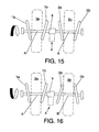
Figure 15 is a front raised schematic view of the second version of the mechanism of this invention in a first massage position, which is achieved when the revolving shafts turn clockwise; -
figure 16 is a front raised schematic view of the mechanism shown infigure 2 , in a second massage position, which is achieved when the revolving shafts turn anticlockwise; -
figure 17 is a cross-section schematic view of a version of a clutch mechanism which can be included in the massage mechanism shown infigures 15 and 16 , when the revolving shafts turn as shown infigure 15 ; -
figure 18 is an upper plane schematic view of the complementary means of actuation shown infigure 17 ; -
figure 19 is a front schematic view of the second bushing shown infigure 17 , from line VII-VII'; -
figure 20 is a cross-section schematic view of the second bushing along line VIII-VIII' shown infigure 19 ; -
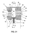
figure 21 is a cross-section schematic view of another version of a clutch mechanism that can be included in the massage mechanism shown infigures 15 and 16 , when the revolving shafts turn as shown infigure 15 ; -
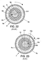
figure 22 is a front schematic view of the second bushing shown infigure 21 , from line IX-IX'; -
figure 23 is a front schematic view of the first bushing shown infigure 21 , from line X-X'; -
figure 24 is a view in perspective of a possible example version of the device of the invention, in which between each of the discs of the pair of discs, different versions are included of an intermediate massage element; -
figure 25 is a lower perspective view of the previous figure; -
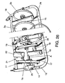
figure 26 is a view offigure 24 , but with the difference that the intermediate massage element is located in another different operating position; -
figures 27 to 30 represent different operating positions of two different types of intermediate massage elements located as lateral extensions of both discs of each pair of discs; -
figure 31 is a view in perspective of another example version in which the intermediate massage element is constituted by a plate provided with means of vibration; -
figure 32 is a lower view offigure 31 ; -
figure 33 shows a view in perspective of the version of the motor, which constitutes the means of vibration of the plate constituting the intermediate massage element; -
figure 34 is a partial view of an example version in which means have been provided to allow the separation between the discs of each pair of discs to be adjusted. - These figures have numbers, and/or letters which identify the following elements:
- A
- first revolving shaft
- A-1
- first end of the first revolving shaft A
- A-2
- second end of the first revolving shaft A
- B
- second revolving shaft
- B-1
- first end of the second revolving shaft B
- B-2
- second end of the second revolving shaft B
- 1a, 1b
- discs of the first pair of discs
- 2a, 2b
- discs of the second pair of discs
- 3a
- lower part of the user's first leg
- 3b
- lower part of the user's second leg
- 4
- actuation mechanism
- 5
- clutch mechanism
- 5a
- clutch housing
- 5b
- internal cavity
- 5c
- intermediate cavity
- 5d
- first cylindrical lateral passage
- 5e
- second cylindrical lateral passage
- 5f
- access passage to the intermediate cavity
- 6
- internal housing
- 6a
- first stop element
- 6b
- second stop element
- 6c
- passage between the stop elements
- 6d
- protrusion
- 7
- first bushing
- 7a
- gearing means in the first bushing
- 7b
- first bushing tab
- 8
- second bushing
- 8a
- gearing means of the second bushing
- 8b
- second bushing tab
- 9
- complementary means of actuation
- 9a
- drive shaft
- 10
- additional internal housing
- 10a
- first additional stop element
- 10b
- second additional stop element
- 10c
- additional passage between the additional stop elements
- 10d
- additional protrusion
- 11
- exterior bushing
- 12
- chassis
- 13
- stop
- 14
- eccentric
- 15
- intermediate massage element
- 16
- cylindrical surface
- 17
- second spring
- 18
- first body
- 19
- cylindrical long body
- 20
- shaft
- 21
- second body
- 22
- semi cylindrical long body
- 23
- third spring
- 24
- first spring
- 25
- pivot
- 26
- fourth spring
- 27
- plate
- 28
- motor
- 29
- motor shafts
- 30
- housing
- 31
- counterweights
- 32
- Bolts
-
Figures 1 and 2 show a first version of the massage mechanism according to the present invention, which includes a first pair ofmassage discs first leg 3a, and a second pair ofmassage discs second leg 3b. The revolvingdiscs discs - Revolving shafts A, B are connected by their respective first ends A-1, B-1 to a clutch mechanism which connects the said shafts A, B together. The first shaft A is connected by its second end A-2 to a bearing, whereas the second end B-2 of the second shaft is connected conventionally to a
conventional actuation mechanism 4, such as an electric motor with reducer unit, capable of giving rotating shafts A, B an anticlockwise rotation (fig. 1 ) and a clockwise rotation (fig.2 ). - The clutch mechanism connects shafts A, B so that when the shafts turn anticlockwise, as shown in
figure 1 , the pairs ofmassage discs legs fig. 2 ), the clutch mechanism causes a dysphase in the first shaft A with regard to its turning approximately 180° with regard to the second shaft B. When this dysphase occurs, the secondrotating discs first massage discs first massage discs first leg 3a, thesecond massage discs second leg 3b and press the corresponding second part of thissecond leg 3b. -
Figures 3 to 8 show a first version of aclutch mechanism 5 which can be included in the massage mechanism offigures 1 and 2 . Thismechanism 5 includes abody 5a with ahousing 10 to which end A-1 of the first revolving shaft A is connected, and anotherhousing 6, formed in axial alignment withhousing 10, to which the second revolving shaft B is connected.Body 5a is housed in anexterior bushing 11. Theinternal housing 6 includes afirst stop element 6a and asecond stop element 6b, avertical section passage 6c arched betweenstop elements protrusion 6d in the form of an axial nerve, which moves through the saidpassage 6c betweenstops passage 6c and thestop elements passage 6c is formed by an interior insert in a part of an internal wall ofhousing 6 to which end B-1 of the second revolving shaft B is connected and moves in the interior insert orpassage 6c. Thehousing 10 includes an insert in which aprotrusion 10d is housed, which emerges from periphery of the first end A-1 of the first shaft A, so that the first shaft A is immobilised in thebody 5a of theclutch mechanism 5.Figures 3 to 5 show the layout ofinsert 6d inpassage 6c when shafts A, B turn anticlockwise, that is, in the position corresponding tofigure 1 . In this situation, theprotrusion 6d comes up against thefirst stop element 6a when shafts A, B turn, and therespective massage discs figure 1 . As can be seen infigure 6 , when the shafts A, B change direction, theprotrusion 6d moves clockwise through thepassage 6c until it reaches the position shown infigures 7 and 8 , coming up against thesecond stop element 6b so that the above-mentioned dysphase of approximately 180° occurs between the shafts A, B and themassage discs figure 2 . - The version of the
clutch mechanism 5 shown infigures 9 to 14 is different from the version infigures 3 to 8 in thatstep 6c is an exterior insert formed on the external perimeter of end B-1 of the second revolving shaft B andprotrusion 6d is an interior protrusion that emerges from the internal perimeter ofhousing 6, and the first shaft A is immobilised inbody 5a of theclutch mechanism 5 by means of a protrusion that emerges from the interior wall ofhousing 10 which fits in a complementary insert in the first end A-1 of the first shaft A. In the position ofmassage discs figure 1 , that is when the revolving shafts A, B turn anticlockwise, theprotrusion 6d stops against thefirst stop element 6a as shown infigures 9 to 11 . When the turning direction of shafts A, B changes, theprotrusion 6d is no longer in contact with thestop element 6a at the first end A-1 of the revolving shaft A, passing through the position shown infigure 12 to the position shown infigures 13 and 14 , in which thesecond stop element 6b comes into contact with theprotrusion 6d, and the dysphase of approximately 180° occurs between the revolving shafts A, B so themassage discs figure 2 . - In the version of the massage mechanism shown in
figures 15 and 16 , theactuation mechanism 4 is in contact withclutch mechanism 5, and in the remainder the operation of this mechanism is similar to that of the version of the mechanism infigures 1 and 2 . -
Figures 17 to 20 show a version ofclutch mechanism 5 that can be included in the massage mechanism infigures 15 and 16 . In this version, theclutch mechanism 5 includes aclutch body 5a with aninternal cavity 5b which includes anintermediate cavity 5c which is connected to a firstcylindrical lateral passage 5d, with a secondcylindrical lateral passage 5e, and with anaccess passage 5f to theintermediate cavity 5c. Theaccess passage 5f is between the said cylindricallateral passages lateral passage 5d afirst bushing 7 is housed revolving, in which the first end A-1 of the first revolving shaft A is inserted. In thesecond lateral passage 5e asecond bushing 8 is housed revolving, in which the first end B-1 of the second revolving shaft B is housed.Bushings intermediate cavity 5c through one of the ends. These ends are both provided withperipheral tabs gearings gearwheel 9 connected by means of adrive shaft 9a to theactuation mechanism 4 which might be, for instance, an electric motor unit with reducer if it is conventional. Theshaft 9a enters theintermediate cavity 5c through theaccess passage 5f. - Inside the
first bushing 7 aninternal housing 10 is formed in which the first end A-1 of the revolving shaft A is immobilised by means of aprotrusion 10 in the form of a radial nerve, which emerges from the said first end A-1 and fits in a complementary insert in the interior wall ofhousing 10. - Inside the
second bushing 8 aninternal housing 6 is formed of the same characteristics as those of thehousing 6 in thebody 5a of the clutch mechanism shown infigures 3 to 8 . Therefore, theinternal housing 6 includes afirst stop element 6a and asecond stop element 6b, apassage 6c with a vertical cross section arched some 180° between thestop elements protrusion 6d in the form of a radial nerve between thestops passage 6c and thestop elements passage 6c is formed by an interior insert in part of an internal wall of thehousing 6, whereas theprotrusion 6d emerges from the external perimeter of the said first end B-1 and moves in theinterior insert 6c. - The operation of the clutch mechanism shown in
figures 17 to 20 is the same as that of the clutch mechanism infigures 3 to 8 , except that theactuation mechanisms 4 are not directly connected to one of the revolving shafts A, B, but turn somebushings bushings stop element 6b in thehousing 6 comes into contact with theradial protrusion 6d which emerges from the first part B-1 of the second revolving shaft B so that this shaft B turns along with thebushing 8 in the same direction, leaving themassage discs figure 15 . Furthermore, when thebushings protrusion 6d, no longer comes up against thestop element 6b, and after approximately half a turn ofbushing 8, it comes into contact with thestop element 6a so that the shaft B begins to turn in the same direction as thebushing 8. Due to the dysphase of approximately 180° which has then been caused between shafts A, B, themassage discs figure 16 . -
Figures 20 to 23 show another version of aclutch mechanism 5 which may be included in the massage mechanism infigures 15 and 16 . This version is different from the version infigures 17 to 20 in that thepassage 6c stretches 90° instead of 180° in the internal wall of thehousing 6 of thesecond bushing 8, and in which theinternal housing 10 in the first bushing has the same configuration as theinternal housing 6 in thesecond bushing 8. Therefore, the additionalinternal housing 10 includes a firstadditional stop element 10a and a secondadditional stop element 10b, anadditional passage 10c with an arched vertical section with an extension of approximately 90° between the saidadditional stop elements additional protrusion 10d between the saidadditional stops additional passage 10c and theadditional stop elements additional passage 10c being an internal insert in an internal wall of theadditional housing 10 in which the said first end A-1 of the first revolving shaft A is coupled, whereas theadditional protrusion 10d emerges from the external perimeter of the first end A-1 of the first revolving shaft A. - When the
bushings stop element 6b in thehousing 6 comes into contact with theradial protrusion 6d which emerges from the first part B-1 of the second revolving shaft B so that this shaft B turns along withbushing 8 in the same sense. In turn, in theinternal housing 10 of thefirst bushing 7, theprotrusion 10d comes into contact with thestop 10a, so that the shaft A turns along with thebushing 7 in the same direction. In this situation, themassage discs figure 15 . - When the
bushings first bushing 7 theprotrusion 10d no longer comes up against thestop element 10a, and after approximately a quarter of a turn ofbushing 7, it comes into contact with thesecond stop element 10b so that the shaft A begins to turn in the same direction as thebushing 7. At the same time, in thesecond bushing 8 theprotrusion 6d no longer comes up against thestop element 6b, and also after approximately a quarter of a turn of thebushing 8, it comes into contact with thestop element 6a so that shaft B starts to turn in the same direction as thebushing 8. Due to the joint dysphase of approximately 180° which has then occurred between the shafts A, B, themassage discs - In
figures 24 to 33 the different versions are shown in which an intermediate massage element is included, as described in the following. These versions have been drawn in greater detail than the previous ones, and do not specify the clutch mechanism to make it easier to understand the intermediate massage element. - In these cases, the mechanism is supported on a
chassis 12 in which it is fixed, allowing the first revolving shaft A, and the second revolving shaft B. to turn by means of amotor 4. - On the revolving shafts A, B the disc pairs 1a, 1b; 2a, 2b are mounted by means of an eccentric 14 so that they are supported on a plane inclined longitudinally towards opposite ends and are moved by changing the information with respect to the length of the leg, which is located on the
discs - The different intermediate massage elements may be located indistinctly between the
first discs second discs - The different massage elements have been represented in the figures depending on the different versions, but, as commented, they may be the same for each of the discs of each pair of discs.
- Therefore, for example, between the
second massage discs leg 3b, and which is finished off at the top by means of acylindrical surface 16 on which the user'sleg 3b is supported longitudinally, so that when the revolving shaft B is activated, a transversal movement is caused on thecylindrical surface 16 with respect to the length of theleg 3b defining roughly a figure "eight", which causes a massage sensation very similar to the "kneading" provided by a masseur. - To keep the
cylindrical surface 16 in contact with the lower part of the leg, theintermediate element 15 is fixed to the chassis, by means of a first elastic element constituted by thefirst spring 24. In this way, when the revolving shaft B turns, theintermediate massage element 15 is prevented from turning, to give the required effect. - Another of the possible versions of the invention provides for the intermediate massage element, instead of being on one of the revolving shafts A, B, being supported on one of the discs, for example on
discs shaft 20 on which it can turn. In the example version, each of thediscs discs 1b, it includes a natural extension provided with afirst body 18 which includes a cylindrical stretchedbody 19 inclined towards the first revolving shaft A. - In the other disc of the first pair of discs, a lateral extension has been provided, which includes a
second body 21 with a semi cylindrical stretchedbody 22 inclined towards shaft A. For these cases, thediscs chassis 12 by means of two opposedsecond springs 17 which preventdiscs first body 18 and thesecond body 21 remain in the required position. Moreover, thesebodies third spring 23 to each of thediscs pivot 25 against which thebodies third spring 23 are kept in contact with the said pivots 25, to keep them in the massage position and not allow them to turn onshaft 20. Thebody 18 includes a cylindrical stretchedbody 19 and the body 21 a semi cylindrical stretchedbody 22, on which the leg to be massaged rests. - This setup determines that when revolving shaft A turns and movement is caused in
discs bodies discs figures 27 to 30 . - In the movement of the
discs bodies bodies pivots 25 help to maintain this safety distance. - In another version of the invention, the intermediate massage element is constituted by a
plate 27 in which the lower face includes ahousing 30 on which amotor 28 has been fixed, provided with twoopposed shafts 29 the end of which have been fixed withcounterweights 31, so that the actuation of themotor 28 causes a vibrating movement in theplate 27, which is fixed by one of its ends withbolts 32 to thechassis 12 to enable its vibration, so that when the rear part of the leg is placed on the plate, this transmits the vibration to the leg, giving it a vibrating massage. - The invention also plans for the massaged area to be of different volumes, as, for example, the volume of the calf muscles of each user varies according to their constitution, which means that the calf muscles are placed differently with respect to the
discs discs fourth spring 26, for example, one end of which comes up against thechassis 12 and the other end coming up against the corresponding discs, for example,disc 2b, which in turn is held by astop 13 so that the action of thefourth spring 26 keeps thediscs discs disc 2a moves axially on the second revolving shaft B, overcoming the action of thespring 26 and thus at adjusting to the volume of the part to be massaged in each user. Once the massaged part is removed, thedisc 2a returns to its position thanks to thefourth spring 26meeting stop 13. This same structure may be applied in the twodiscs - In the preferred version of the invention, all of the
massage discs fourth spring 26 to achieve a greater margin for adaptation to the different volumes of the parts to be massaged, so that the movement occurs overcoming the action of thefourth springs 26 of bothdiscs
Claims (35)
and the stop elements (6a, 6b) and the protrusion (6d) are laid out in such a way that the protrusion (6d) comes into contact with one of the stop elements (6a, 6b) when the revolving shafts (A, B) turn in the first direction, and comes into contact with the opposite stop element (6a, 6b) when the revolving shafts (A, B) turn in the second direction.
the additional passage (10c) and the additional stop elements (10a, 10b) are set out on a plane perpendicular to the longitudinal axis of the revolving shafts (A, B); the additional passage (10c) is an insert selected between an additional exterior insert formed at a first end (A-1) of the external perimeter of the first revolving shaft (A) and an additional interior insert in an internal wall of the additional housing (10) to which the said first end (A-1) of the first revolving shaft (A) is connected; the additional protrusion (10d) is selected between an additional interior protrusion which emerges from the internal perimeter of the additional housing (10), and an additional exterior protrusion which emerges from the external perimeter of the first end (A-1) of the first revolving shaft (A); the additional stop elements (10a, 10b) and the additional protrusion (10d) are set out so that the additional protrusion (10d) comes into contact with one of the additional stop elements (10a, 10b) when the revolving shafts (A, B) turn in the first direction, and comes into contact with the other additional stop element (10a, 10b) when the revolving shafts (A, B) turn in the second opposed direction.
Applications Claiming Priority (2)
| Application Number | Priority Date | Filing Date | Title |
|---|---|---|---|
| ES200601949A ES2289944B1 (en) | 2006-07-21 | 2006-07-21 | MECHANISM FOR THE MASSAGE OF THE LOWER PARTS OF THE LEGS OF A USER. |
| PCT/ES2007/000015 WO2008012379A1 (en) | 2006-07-21 | 2007-02-15 | Mechanism for massaging the lower parts of a user's legs |
Publications (3)
| Publication Number | Publication Date |
|---|---|
| EP2055289A1 true EP2055289A1 (en) | 2009-05-06 |
| EP2055289A4 EP2055289A4 (en) | 2016-03-23 |
| EP2055289B1 EP2055289B1 (en) | 2019-05-15 |
Family
ID=38961564
Family Applications (1)
| Application Number | Title | Priority Date | Filing Date |
|---|---|---|---|
| EP07704729.8A Active EP2055289B1 (en) | 2006-07-21 | 2007-02-15 | Mechanism for massaging the lower parts of a user's legs |
Country Status (3)
| Country | Link |
|---|---|
| EP (1) | EP2055289B1 (en) |
| ES (2) | ES2289944B1 (en) |
| WO (1) | WO2008012379A1 (en) |
Cited By (1)
| Publication number | Priority date | Publication date | Assignee | Title |
|---|---|---|---|---|
| JP2024082824A (en) * | 2022-12-09 | 2024-06-20 | 大東電機工業株式会社 | Lumbar massage machine |
Families Citing this family (1)
| Publication number | Priority date | Publication date | Assignee | Title |
|---|---|---|---|---|
| CN111466710B (en) * | 2020-04-09 | 2021-03-16 | 杭州荣正家具有限公司 | Can alleviate tired intelligent desk of shank |
Family Cites Families (16)
| Publication number | Priority date | Publication date | Assignee | Title |
|---|---|---|---|---|
| JPS5198181A (en) * | 1975-02-26 | 1976-08-28 | ||
| JPS5928963A (en) | 1982-08-10 | 1984-02-15 | 松下電工株式会社 | Massager |
| JPH02109628A (en) | 1988-10-20 | 1990-04-23 | Mitsubishi Heavy Ind Ltd | Device for measuring phase difference |
| JPH0478307A (en) | 1990-07-20 | 1992-03-12 | Kosumetsuku:Kk | Pressure oil supplying and exhausting device for hydraulic cylinder |
| CN1195473C (en) | 1998-05-07 | 2005-04-06 | 大东电机工业株式会社 | Roller massage mechanism and massage device with built-in massage mechanism |
| JP3046804B2 (en) * | 1998-10-21 | 2000-05-29 | 大東電機工業株式会社 | Roller massage machine |
| JP3911101B2 (en) * | 1999-03-29 | 2007-05-09 | ファミリー株式会社 | Foot massage machine |
| JP3339849B2 (en) * | 2000-04-06 | 2002-10-28 | 大東電機工業株式会社 | Lower limb massage machine and chair-type massage device using this massage machine |
| JP3377195B2 (en) | 2001-06-22 | 2003-02-17 | 大東電機工業株式会社 | Lower limb massage machine and chair-type massage device using this massage machine |
| US6599261B1 (en) * | 2002-01-23 | 2003-07-29 | Hsin Hao Health Materials Co., Ltd. | Massaging device |
| US6969361B2 (en) * | 2003-05-22 | 2005-11-29 | Wen-Hsu Hsieh | Leg massage device |
| JP2005000403A (en) * | 2003-06-12 | 2005-01-06 | Omron Healthcare Co Ltd | Massage machine |
| ES2235651B1 (en) * | 2003-12-23 | 2006-10-16 | Eurokeyton, S.A. | MASSAGE DEVICE. |
| US7108669B2 (en) * | 2004-09-29 | 2006-09-19 | Chien-Ming Huang | Massager |
| US7108670B2 (en) * | 2004-09-29 | 2006-09-19 | Chien-Ming Huang | Limb massager |
| US7060043B2 (en) * | 2004-10-01 | 2006-06-13 | Chien-Ming Huang | Massage device |
-
2006
- 2006-07-21 ES ES200601949A patent/ES2289944B1/en not_active Expired - Fee Related
-
2007
- 2007-02-15 ES ES07704729T patent/ES2741889T3/en active Active
- 2007-02-15 EP EP07704729.8A patent/EP2055289B1/en active Active
- 2007-02-15 WO PCT/ES2007/000015 patent/WO2008012379A1/en not_active Ceased
Non-Patent Citations (1)
| Title |
|---|
| See references of WO2008012379A1 * |
Cited By (1)
| Publication number | Priority date | Publication date | Assignee | Title |
|---|---|---|---|---|
| JP2024082824A (en) * | 2022-12-09 | 2024-06-20 | 大東電機工業株式会社 | Lumbar massage machine |
Also Published As
| Publication number | Publication date |
|---|---|
| ES2289944A1 (en) | 2008-02-01 |
| WO2008012379A1 (en) | 2008-01-31 |
| EP2055289A4 (en) | 2016-03-23 |
| EP2055289B1 (en) | 2019-05-15 |
| ES2289944B1 (en) | 2008-12-16 |
| ES2741889T3 (en) | 2020-02-12 |
Similar Documents
| Publication | Publication Date | Title |
|---|---|---|
| CN101820846B (en) | Massage machines and chair-type massage devices | |
| JP3339849B2 (en) | Lower limb massage machine and chair-type massage device using this massage machine | |
| KR100231146B1 (en) | Chair massage | |
| JP3354576B2 (en) | Roller massage mechanism and massage device incorporating this mechanism | |
| CN102341083B (en) | massage machine | |
| CN100394905C (en) | Messager | |
| EP2055289B1 (en) | Mechanism for massaging the lower parts of a user's legs | |
| JP5838377B2 (en) | Massage machine | |
| KR102841130B1 (en) | Massage Instrument Having Separated Massage Modules | |
| CN101808605A (en) | Massage unit and massage machine having same | |
| JP4223838B2 (en) | Chair type massage device | |
| JP4223839B2 (en) | 4-ball massage mechanism and massage device with built-in this mechanism | |
| JP5199810B2 (en) | Massage equipment | |
| JP6936477B2 (en) | Massage machine | |
| CN104414835B (en) | massage machine | |
| JP2011194142A (en) | Massage device | |
| JP2007325633A (en) | Massage machine and chair type massage machine | |
| JP2018064808A (en) | Massage machine | |
| TW201808246A (en) | Lower limb massage machine for shank massage capable of not neglecting any one side of massaging portion and without stressing too much causing pain or discomfort | |
| JP2005080782A (en) | Lower limb massage machine and chair type massage device using this massage machine | |
| CN119012990A (en) | Massaging machine | |
| KR200412962Y1 (en) | Massager with thigh massager and chair | |
| JP4670564B2 (en) | Massage machine | |
| JP2001314463A (en) | Portable pinching massage machine | |
| JP3839457B1 (en) | Leg exercise assist device |
Legal Events
| Date | Code | Title | Description |
|---|---|---|---|
| PUAI | Public reference made under article 153(3) epc to a published international application that has entered the european phase |
Free format text: ORIGINAL CODE: 0009012 |
|
| 17P | Request for examination filed |
Effective date: 20090219 |
|
| AK | Designated contracting states |
Kind code of ref document: A1 Designated state(s): AT BE BG CH CY CZ DE DK EE ES FI FR GB GR HU IE IS IT LI LT LU LV MC NL PL PT RO SE SI SK TR |
|
| AX | Request for extension of the european patent |
Extension state: AL BA HR MK RS |
|
| DAX | Request for extension of the european patent (deleted) | ||
| RIN1 | Information on inventor provided before grant (corrected) |
Inventor name: NAVARRO ARCAS, ABEL RIQUELME Inventor name: CANTO GARCIA, ENRIQUE |
|
| RA4 | Supplementary search report drawn up and despatched (corrected) |
Effective date: 20160222 |
|
| RIC1 | Information provided on ipc code assigned before grant |
Ipc: A61H 15/00 20060101AFI20160216BHEP |
|
| 17Q | First examination report despatched |
Effective date: 20160310 |
|
| STAA | Information on the status of an ep patent application or granted ep patent |
Free format text: STATUS: EXAMINATION IS IN PROGRESS |
|
| R17C | First examination report despatched (corrected) |
Effective date: 20161111 |
|
| 17Q | First examination report despatched |
Effective date: 20170116 |
|
| GRAP | Despatch of communication of intention to grant a patent |
Free format text: ORIGINAL CODE: EPIDOSNIGR1 |
|
| STAA | Information on the status of an ep patent application or granted ep patent |
Free format text: STATUS: GRANT OF PATENT IS INTENDED |
|
| INTG | Intention to grant announced |
Effective date: 20181128 |
|
| GRAS | Grant fee paid |
Free format text: ORIGINAL CODE: EPIDOSNIGR3 |
|
| GRAA | (expected) grant |
Free format text: ORIGINAL CODE: 0009210 |
|
| STAA | Information on the status of an ep patent application or granted ep patent |
Free format text: STATUS: THE PATENT HAS BEEN GRANTED |
|
| AK | Designated contracting states |
Kind code of ref document: B1 Designated state(s): AT BE BG CH CY CZ DE DK EE ES FI FR GB GR HU IE IS IT LI LT LU LV MC NL PL PT RO SE SI SK TR |
|
| REG | Reference to a national code |
Ref country code: CH Ref legal event code: EP Ref country code: GB Ref legal event code: FG4D |
|
| REG | Reference to a national code |
Ref country code: DE Ref legal event code: R096 Ref document number: 602007058371 Country of ref document: DE |
|
| REG | Reference to a national code |
Ref country code: IE Ref legal event code: FG4D |
|
| REG | Reference to a national code |
Ref country code: NL Ref legal event code: MP Effective date: 20190515 |
|
| REG | Reference to a national code |
Ref country code: LT Ref legal event code: MG4D |
|
| PG25 | Lapsed in a contracting state [announced via postgrant information from national office to epo] |
Ref country code: PT Free format text: LAPSE BECAUSE OF FAILURE TO SUBMIT A TRANSLATION OF THE DESCRIPTION OR TO PAY THE FEE WITHIN THE PRESCRIBED TIME-LIMIT Effective date: 20190915 Ref country code: LT Free format text: LAPSE BECAUSE OF FAILURE TO SUBMIT A TRANSLATION OF THE DESCRIPTION OR TO PAY THE FEE WITHIN THE PRESCRIBED TIME-LIMIT Effective date: 20190515 Ref country code: NL Free format text: LAPSE BECAUSE OF FAILURE TO SUBMIT A TRANSLATION OF THE DESCRIPTION OR TO PAY THE FEE WITHIN THE PRESCRIBED TIME-LIMIT Effective date: 20190515 Ref country code: FI Free format text: LAPSE BECAUSE OF FAILURE TO SUBMIT A TRANSLATION OF THE DESCRIPTION OR TO PAY THE FEE WITHIN THE PRESCRIBED TIME-LIMIT Effective date: 20190515 Ref country code: SE Free format text: LAPSE BECAUSE OF FAILURE TO SUBMIT A TRANSLATION OF THE DESCRIPTION OR TO PAY THE FEE WITHIN THE PRESCRIBED TIME-LIMIT Effective date: 20190515 |
|
| PG25 | Lapsed in a contracting state [announced via postgrant information from national office to epo] |
Ref country code: LV Free format text: LAPSE BECAUSE OF FAILURE TO SUBMIT A TRANSLATION OF THE DESCRIPTION OR TO PAY THE FEE WITHIN THE PRESCRIBED TIME-LIMIT Effective date: 20190515 Ref country code: GR Free format text: LAPSE BECAUSE OF FAILURE TO SUBMIT A TRANSLATION OF THE DESCRIPTION OR TO PAY THE FEE WITHIN THE PRESCRIBED TIME-LIMIT Effective date: 20190816 Ref country code: BG Free format text: LAPSE BECAUSE OF FAILURE TO SUBMIT A TRANSLATION OF THE DESCRIPTION OR TO PAY THE FEE WITHIN THE PRESCRIBED TIME-LIMIT Effective date: 20190815 |
|
| REG | Reference to a national code |
Ref country code: AT Ref legal event code: MK05 Ref document number: 1132581 Country of ref document: AT Kind code of ref document: T Effective date: 20190515 |
|
| PG25 | Lapsed in a contracting state [announced via postgrant information from national office to epo] |
Ref country code: CZ Free format text: LAPSE BECAUSE OF FAILURE TO SUBMIT A TRANSLATION OF THE DESCRIPTION OR TO PAY THE FEE WITHIN THE PRESCRIBED TIME-LIMIT Effective date: 20190515 Ref country code: RO Free format text: LAPSE BECAUSE OF FAILURE TO SUBMIT A TRANSLATION OF THE DESCRIPTION OR TO PAY THE FEE WITHIN THE PRESCRIBED TIME-LIMIT Effective date: 20190515 Ref country code: SK Free format text: LAPSE BECAUSE OF FAILURE TO SUBMIT A TRANSLATION OF THE DESCRIPTION OR TO PAY THE FEE WITHIN THE PRESCRIBED TIME-LIMIT Effective date: 20190515 Ref country code: EE Free format text: LAPSE BECAUSE OF FAILURE TO SUBMIT A TRANSLATION OF THE DESCRIPTION OR TO PAY THE FEE WITHIN THE PRESCRIBED TIME-LIMIT Effective date: 20190515 Ref country code: AT Free format text: LAPSE BECAUSE OF FAILURE TO SUBMIT A TRANSLATION OF THE DESCRIPTION OR TO PAY THE FEE WITHIN THE PRESCRIBED TIME-LIMIT Effective date: 20190515 Ref country code: DK Free format text: LAPSE BECAUSE OF FAILURE TO SUBMIT A TRANSLATION OF THE DESCRIPTION OR TO PAY THE FEE WITHIN THE PRESCRIBED TIME-LIMIT Effective date: 20190515 |
|
| REG | Reference to a national code |
Ref country code: ES Ref legal event code: FG2A Ref document number: 2741889 Country of ref document: ES Kind code of ref document: T3 Effective date: 20200212 |
|
| REG | Reference to a national code |
Ref country code: DE Ref legal event code: R097 Ref document number: 602007058371 Country of ref document: DE |
|
| PG25 | Lapsed in a contracting state [announced via postgrant information from national office to epo] |
Ref country code: IT Free format text: LAPSE BECAUSE OF FAILURE TO SUBMIT A TRANSLATION OF THE DESCRIPTION OR TO PAY THE FEE WITHIN THE PRESCRIBED TIME-LIMIT Effective date: 20190515 |
|
| PLBE | No opposition filed within time limit |
Free format text: ORIGINAL CODE: 0009261 |
|
| STAA | Information on the status of an ep patent application or granted ep patent |
Free format text: STATUS: NO OPPOSITION FILED WITHIN TIME LIMIT |
|
| PG25 | Lapsed in a contracting state [announced via postgrant information from national office to epo] |
Ref country code: TR Free format text: LAPSE BECAUSE OF FAILURE TO SUBMIT A TRANSLATION OF THE DESCRIPTION OR TO PAY THE FEE WITHIN THE PRESCRIBED TIME-LIMIT Effective date: 20190515 |
|
| 26N | No opposition filed |
Effective date: 20200218 |
|
| PG25 | Lapsed in a contracting state [announced via postgrant information from national office to epo] |
Ref country code: PL Free format text: LAPSE BECAUSE OF FAILURE TO SUBMIT A TRANSLATION OF THE DESCRIPTION OR TO PAY THE FEE WITHIN THE PRESCRIBED TIME-LIMIT Effective date: 20190515 |
|
| PG25 | Lapsed in a contracting state [announced via postgrant information from national office to epo] |
Ref country code: SI Free format text: LAPSE BECAUSE OF FAILURE TO SUBMIT A TRANSLATION OF THE DESCRIPTION OR TO PAY THE FEE WITHIN THE PRESCRIBED TIME-LIMIT Effective date: 20190515 |
|
| REG | Reference to a national code |
Ref country code: DE Ref legal event code: R119 Ref document number: 602007058371 Country of ref document: DE |
|
| REG | Reference to a national code |
Ref country code: CH Ref legal event code: PL |
|
| GBPC | Gb: european patent ceased through non-payment of renewal fee |
Effective date: 20200215 |
|
| REG | Reference to a national code |
Ref country code: BE Ref legal event code: MM Effective date: 20200229 |
|
| PG25 | Lapsed in a contracting state [announced via postgrant information from national office to epo] |
Ref country code: LU Free format text: LAPSE BECAUSE OF NON-PAYMENT OF DUE FEES Effective date: 20200215 Ref country code: MC Free format text: LAPSE BECAUSE OF FAILURE TO SUBMIT A TRANSLATION OF THE DESCRIPTION OR TO PAY THE FEE WITHIN THE PRESCRIBED TIME-LIMIT Effective date: 20190515 |
|
| PG25 | Lapsed in a contracting state [announced via postgrant information from national office to epo] |
Ref country code: LI Free format text: LAPSE BECAUSE OF NON-PAYMENT OF DUE FEES Effective date: 20200229 Ref country code: CH Free format text: LAPSE BECAUSE OF NON-PAYMENT OF DUE FEES Effective date: 20200229 |
|
| PG25 | Lapsed in a contracting state [announced via postgrant information from national office to epo] |
Ref country code: GB Free format text: LAPSE BECAUSE OF NON-PAYMENT OF DUE FEES Effective date: 20200215 Ref country code: FR Free format text: LAPSE BECAUSE OF NON-PAYMENT OF DUE FEES Effective date: 20200229 Ref country code: IE Free format text: LAPSE BECAUSE OF NON-PAYMENT OF DUE FEES Effective date: 20200215 Ref country code: DE Free format text: LAPSE BECAUSE OF NON-PAYMENT OF DUE FEES Effective date: 20200901 |
|
| PG25 | Lapsed in a contracting state [announced via postgrant information from national office to epo] |
Ref country code: BE Free format text: LAPSE BECAUSE OF NON-PAYMENT OF DUE FEES Effective date: 20200229 |
|
| PG25 | Lapsed in a contracting state [announced via postgrant information from national office to epo] |
Ref country code: CY Free format text: LAPSE BECAUSE OF FAILURE TO SUBMIT A TRANSLATION OF THE DESCRIPTION OR TO PAY THE FEE WITHIN THE PRESCRIBED TIME-LIMIT Effective date: 20190515 |
|
| PG25 | Lapsed in a contracting state [announced via postgrant information from national office to epo] |
Ref country code: IS Free format text: LAPSE BECAUSE OF FAILURE TO SUBMIT A TRANSLATION OF THE DESCRIPTION OR TO PAY THE FEE WITHIN THE PRESCRIBED TIME-LIMIT Effective date: 20190915 |
|
| PGFP | Annual fee paid to national office [announced via postgrant information from national office to epo] |
Ref country code: ES Payment date: 20230530 Year of fee payment: 17 |
|
| REG | Reference to a national code |
Ref country code: ES Ref legal event code: FD2A Effective date: 20250331 |
|
| PG25 | Lapsed in a contracting state [announced via postgrant information from national office to epo] |
Ref country code: ES Free format text: LAPSE BECAUSE OF NON-PAYMENT OF DUE FEES Effective date: 20240216 |