EP2055219A2 - Wheel connection apparatus and cleaner having the same - Google Patents
Wheel connection apparatus and cleaner having the same Download PDFInfo
- Publication number
- EP2055219A2 EP2055219A2 EP08103097A EP08103097A EP2055219A2 EP 2055219 A2 EP2055219 A2 EP 2055219A2 EP 08103097 A EP08103097 A EP 08103097A EP 08103097 A EP08103097 A EP 08103097A EP 2055219 A2 EP2055219 A2 EP 2055219A2
- Authority
- EP
- European Patent Office
- Prior art keywords
- axis
- wheel
- cleaner body
- cleaner
- connection apparatus
- Prior art date
- Legal status (The legal status is an assumption and is not a legal conclusion. Google has not performed a legal analysis and makes no representation as to the accuracy of the status listed.)
- Withdrawn
Links
Images
Classifications
-
- A—HUMAN NECESSITIES
- A47—FURNITURE; DOMESTIC ARTICLES OR APPLIANCES; COFFEE MILLS; SPICE MILLS; SUCTION CLEANERS IN GENERAL
- A47L—DOMESTIC WASHING OR CLEANING; SUCTION CLEANERS IN GENERAL
- A47L9/00—Details or accessories of suction cleaners, e.g. mechanical means for controlling the suction or for effecting pulsating action; Storing devices specially adapted to suction cleaners or parts thereof; Carrying-vehicles specially adapted for suction cleaners
- A47L9/009—Carrying-vehicles; Arrangements of trollies or wheels; Means for avoiding mechanical obstacles
-
- A—HUMAN NECESSITIES
- A47—FURNITURE; DOMESTIC ARTICLES OR APPLIANCES; COFFEE MILLS; SPICE MILLS; SUCTION CLEANERS IN GENERAL
- A47L—DOMESTIC WASHING OR CLEANING; SUCTION CLEANERS IN GENERAL
- A47L9/00—Details or accessories of suction cleaners, e.g. mechanical means for controlling the suction or for effecting pulsating action; Storing devices specially adapted to suction cleaners or parts thereof; Carrying-vehicles specially adapted for suction cleaners
-
- B—PERFORMING OPERATIONS; TRANSPORTING
- B60—VEHICLES IN GENERAL
- B60B—VEHICLE WHEELS; CASTORS; AXLES FOR WHEELS OR CASTORS; INCREASING WHEEL ADHESION
- B60B19/00—Wheels not otherwise provided for or having characteristics specified in one of the subgroups of this group
-
- B—PERFORMING OPERATIONS; TRANSPORTING
- B60—VEHICLES IN GENERAL
- B60B—VEHICLE WHEELS; CASTORS; AXLES FOR WHEELS OR CASTORS; INCREASING WHEEL ADHESION
- B60B3/00—Disc wheels, i.e. wheels with load-supporting disc body
- B60B3/001—Lightweight wheels, e.g. for strollers or toys
-
- B—PERFORMING OPERATIONS; TRANSPORTING
- B60—VEHICLES IN GENERAL
- B60B—VEHICLE WHEELS; CASTORS; AXLES FOR WHEELS OR CASTORS; INCREASING WHEEL ADHESION
- B60B37/00—Wheel-axle combinations, e.g. wheel sets
Definitions
- the present invention relates to a wheel connection apparatus, and more particularly to a wheel connection apparatus applied to cleaning apparatus.
- Wheels may be classified as fixed wheels and free wheels. Fixed wheels are firmly attached to a cleaner body, whereas free wheels are movably attached to a cleaner body. If only fixed wheels are mounted on a cleaner body, it is difficult for the cleaner body to change direction. Therefore, a cleaner body typically has both fixed wheel and free wheels. However, while such a cleaner body can turn while moving over a surface, it cannot turn without moving.
- Both fixed wheels and free wheels are widely used in cleaners.
- the cleaner moves in various directions. That is, the cleaner may move forward or backward, or turn to the right or left.
- one free wheel is generally provided on the front part of the cleaner and two fixed wheels are provided on the rear part of the cleaner.
- the center of gravity of a cleaner is generally located at the rear part of the cleaner body wherein the motor is mounted.
- the fixed wheels do not rotate, i.e., roll, but rather are dragged. Accordingly, a user may have to use excessive force to drag the cleaner.
- the cleaner body may lose its balance and tumble over because the fixed wheels do rotate.
- a non-limiting object of the present invention is to provide a wheel connection apparatus that includes a first axis rotatably connected to a wheel, a second axis rotatably connected to a cleaner body, and a frame that supports the first axis and the second axis and prevents the first axis and the second axis from becoming separated from the cleaner body and the wheel, the first axis and the second axis being arranged at a predetermined distance from each other.
- the frame may include a protrusion that prevents the first axis and the second axis from becoming separated from the cleaner body and the wheel.
- the wheel connection apparatus may also include a first rotation restriction member disposed on a side of the wheel that restricts the angle of rotation of the wheel, and the first rotation restriction member may protrude from a part of the first axis.
- the wheel connection apparatus may also include a second rotation restriction member disposed on a side of the cleaner body that restricts the angle of rotation of the cleaner body, and the second rotation restriction member may protrude from a part of the second axis.
- a cleaner including a cleaner body, a plurality of wheels which enable the cleaner body to move, and a plurality of wheel connection apparatuses that connect each respective wheel to the cleaner body.
- the cleaner body may turn about the wheel at a predetermined angle without the wheel rotating about its own axis.
- a shock absorbing member may be formed on a part of the cleaner body opposite the wheel, and the shock absorbing member may be made of rubber.
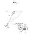
- FIG. 1 is an isometric view illustrating a vacuum cleaner 100 according to an exemplary embodiment of the present invention.
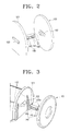
- FIGS. 2 and 3 are isometric views illustrating a wheel connection apparatus connecting a wheel to a cleaner body.
- the vacuum cleaner 100 may comprise a suction nozzle assembly 110, a suction hose 115, a cleaner body 120, a wheel 130, and a wheel connection apparatus 140.
- the suction nozzle assembly 110 is designed to be gripped by a user, and is used to draw dust and dirt into the vacuum cleaner 100.
- the dust and dirt drawn in by the suction nozzle assembly 110 through the suction hose 115 moves to a storage space in the cleaner body 120.
- the functions and constructions of the suction nozzle assembly 110 and the suction hose 115 may include those well-known to persons skilled in the art, and thus detailed descriptions are omitted.
- the cleaner body 120 may comprise a motor to generate a suction force, and a storage unit to collect the drawn-in dust.
- the cleaner body 120 may comprise a housing 121, a first connection member 122 disposed to the cleaner body 120, and a shock absorbing member 123.
- the housing 121 protects internal components of the cleaner body 120.
- the first connection member 122 is configured to connect to a wheel connection apparatus 140.
- the shock absorbing member 123 absorbs impacts between the cleaner body 120 and the wheel 130.
- the shock absorbing member 123 is disposed in an area of the housing 121 with which the wheel 130 may collide.
- the shock absorbing member 123 may be made of rubber.
- the wheel 130 comprises a second connection member 132, and enables the cleaner body 120 to be moved over a surface being cleaner by a user.
- the second connection member 132 configured to connect to the wheel connection apparatus 140.
- the wheel connection apparatus 140 connects the wheel 130 with the cleaner body 120 to facilitate the movement of the cleaner body 120, and may comprise a first axis 141, a second axis 143, a frame 145, a first rotation restriction member 146 ( FIGS. 6A and 6B ) disposed at the first axis 141, and a second rotation restriction member 147 ( FIGS. 6A and 6B ) disposed at the second axis 143.
- the first axis 141 is rotatably connected to the second connection member 132.
- the second connection member 132 may have a shape complementary to the shape of the first axis 141 so that, for example, when the second connection member 132 has an opened part, the first axis 141 can be inserted into the opened part.
- the second connection member 132 may be made of elastic material in order to stretch to receive the first axis 141 when the first axis 141 is inserted into the opened part of the second connection member 132 and to return to its original position when the first axis 141 is completely inserted into the opened part of the second connection member 132, thereby holding the first axis 131 in place.
- the wheel 130 is capable of rotating about the first axis 141.
- the second axis 143 is rotatably connected to the first connection member 122.
- the first connection member 122 may have a shape complementary to the shape to the second axis 143 so that, for example, when the first connection member 122 has an opened part, the second axis 143 can be inserted into the opened part.
- the first connection member 122 is made of elastic material in order to stretch to receive the second axis 143 when the second axis 143 is inserted into the opened part of the first connection member 122 and to return to its original position when the second axis 143 is completely inserted into the opened part of the first connection member 122, thereby holding the second axis 143 in place.
- the cleaner body 130 is capable of rotating about the second axis 143.
- the first connection member 122 and the second connection member 132 are merely exemplary embodiments of the present invention.
- the first connection member 122 and the second connection member 132 may be embodied in various forms which enable the first axis 141 to be rotatably connected to the wheel 130 and the second axis 143 to be rotatably connected to the cleaner body 120.
- the second connection member 132 may be separably connected to the wheel 130 or may be formed with the wheel 130 as a single body 130.
- the frame 145 supports the first axis 141 and second axis 143 and separates the first axis 141 from the second axis 143 by a predetermined distance.
- the frame 145 is disposed at upper and lower surfaces of each of the first axis 141 and the second axis 143.
- the frame 145 may be disposed at middle parts of the first axis 141 and second axis 143.
- the frame 145 may have various structures to separate the first axis 141 and second axis 143 by a predetermined distance and to support the first axis 141 and second axis 143.
- a protrusion 145a is formed on the frame 145 to prevent the first axis 141 and second axis 143 from becoming separated from the first connection member 122 and the second connection member 132, respectively. As illustrated in FIGS. 6A and 6B , the protrusion 145a extends beyond the first axis 141 and second axis 143 so as to interfere with the first connection member 122 or the second connection member 132 when the first or second axis 141 or 143 moves vertically in an axial direction along the first axis 141 and second axis 143. Accordingly, the first axis 141 and second axis 143 do not become separated from the first connection member 122 and the second connection member 132.
- the protrusion 145a is merely an exemplary embodiment of the present invention and various structures may be employed to prevent the first axis 141 and second axis 143 from becoming separated from the first connection member 122 and the second connection member 132, respectively.
- the protrusion 145a may be directly formed on the first axis 141 and second axis 143 instead of the frame 145.
- the first rotation restriction member 146 restricts the angle of movement of the wheel 130 about the first axis 141.
- the second rotation restriction member 147 restricts the angle of movement of the cleaner body 120 about the second axis 143.
- the first rotation restriction member 146 and the second rotation restriction member 147 are explained in more detail below.
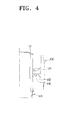
- FIG. 4 is a plan view illustrating a wheel connection apparatus connecting a wheel to the cleaner body.
- the wheel connection apparatus 140 connects the wheel 130 to the cleaner body 120 so that the cleaner body 120 is capable of rotating about its original position at a predetermined angle without the wheels 130 rotating or dragging.
- the vacuum cleaner according to an exemplary embodiment of the present invention moves more freely than a conventional vacuum cleaner. When the cleaner body 120 changes its direction of movement, excessive force is not required, so a user can more easily change the direction of the cleaner body 120.
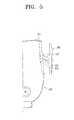
- FIG. 5 is a plan view illustrating a situation in which a user rotates the cleaner body 120 to the right.
- the cleaner body 120 turns about the second axis 143 of the wheel connection apparatus 140, and the wheel 130 rotates about the first axis 141 of the wheel connection apparatus 140, the cleaner body 120 rotates relative to the wheel 130 without the wheels rotating about their own axis, i.e., without the wheels rolling.
- This rotation of the cleaner body 120 is illustrated in FIG. 5 by way of comparison to the orientation of the cleaner body 120 and connection apparatus illustrated in FIG. 4 .
- a user may grip the suction nozzle assembly 110 and clean a wide area, and may thereby repeatedly put pressure on a connection part between the suction hose 115 and the cleaner body 120.
- the cleaner body 120 of the present invention turns at a predetermined angel, the force applied to the connection part is mitigated. Accordingly, less force is required to change the direction of the cleaner body 120, and a user can more easily move the cleaner body 120.
- the rotation of the cleaner body 120 may be uncontrolled such that the cleaner body 120 collides with a wheel 130. Accordingly, to absorb any resulting shock between the cleaner body 120 and the wheel 130, the shock absorbing member 123 may be formed on a predetermined part of the cleaner body 120 opposite the wheel 130 corresponding to where the cleaner body 120 and wheel 130 collide.
- the shock absorbing member 123 may be made of rubber.
- the first rotation restriction member 146 which adjusts the rotation angle of the wheel 130
- the second rotation restriction member 147 which adjusts the rotation angle of the cleaner body 120, may be used to absorb the shock.
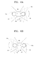
- FIG. 6A is a cross-sectional view illustrating the operation of a rotation restriction member 146 disposed on a wheel 130.
- the first rotation restriction member 146 protrudes from a part of the first axis 141 and is formed opposite the wheel 130 on the first axis 141.
- the second connection member 132 and the first rotation restriction member 146 may hit each other such that the rotation of the wheel 130 about the first axis 141 is restricted. Accordingly, the cleaner body 120 and the wheel 130 are prevented from colliding with each other.
- FIG. 6B is a cross-sectional view illustrating the operation of a rotation restriction member 147 disposed on a cleaner body 120.
- the second rotation restriction member 147 protrudes from a part of the second axis 143 and is formed opposite the cleaner body 120 on the second axis 143.
- the first connection member 122 and the second rotation restriction member 147 may hit each other such that the rotation of the cleaner body 130 about the second axis 143 is restricted. Accordingly, the cleaner body 120 and the wheel 130 are prevented from colliding with each other.
- the first rotation restriction member 146 and second rotation restriction member 147 are merely exemplary embodiments of the present invention, and various structures may be employed to prevent the wheel 130 and cleaner body 120 from colliding with each other.
- a cleaner body 120 is capable of rotating about its original position at a predetermined angle without the wheels 130 rotating about their own axis, i.e., rolling, or dragging so that the cleaner body moves more freely. Accordingly, when a user changes the direction of movement of the cleaner body, the cleaner body moves more smoothly and with less force.
Landscapes
- Engineering & Computer Science (AREA)
- Mechanical Engineering (AREA)
- Electric Suction Cleaners (AREA)
- Vehicle Body Suspensions (AREA)
Abstract
Description
- This application claims the benefit under 35 U.S.C. § 119 of Korean Patent Application No.
10-2007-0109205, filed on October 29, 2007 - The present invention relates to a wheel connection apparatus, and more particularly to a wheel connection apparatus applied to cleaning apparatus.
- Wheels may be classified as fixed wheels and free wheels. Fixed wheels are firmly attached to a cleaner body, whereas free wheels are movably attached to a cleaner body. If only fixed wheels are mounted on a cleaner body, it is difficult for the cleaner body to change direction. Therefore, a cleaner body typically has both fixed wheel and free wheels. However, while such a cleaner body can turn while moving over a surface, it cannot turn without moving.
- Both fixed wheels and free wheels are widely used in cleaners. When a user uses the cleaner to clean a surface, the cleaner moves in various directions. That is, the cleaner may move forward or backward, or turn to the right or left. To support this type of movement, one free wheel is generally provided on the front part of the cleaner and two fixed wheels are provided on the rear part of the cleaner.
- The center of gravity of a cleaner is generally located at the rear part of the cleaner body wherein the motor is mounted. When a user changes the direction of the cleaner abruptly while cleaning a surface, the fixed wheels do not rotate, i.e., roll, but rather are dragged. Accordingly, a user may have to use excessive force to drag the cleaner. Furthermore when the cleaner turns sharply, the cleaner body may lose its balance and tumble over because the fixed wheels do rotate.
- Accordingly, to solve at least the above problems and/or disadvantages and to provide at least the advantages described below, a non-limiting object of the present invention is to provide a wheel connection apparatus that includes a first axis rotatably connected to a wheel, a second axis rotatably connected to a cleaner body, and a frame that supports the first axis and the second axis and prevents the first axis and the second axis from becoming separated from the cleaner body and the wheel, the first axis and the second axis being arranged at a predetermined distance from each other.
- The frame may include a protrusion that prevents the first axis and the second axis from becoming separated from the cleaner body and the wheel. The wheel connection apparatus may also include a first rotation restriction member disposed on a side of the wheel that restricts the angle of rotation of the wheel, and the first rotation restriction member may protrude from a part of the first axis. The wheel connection apparatus may also include a second rotation restriction member disposed on a side of the cleaner body that restricts the angle of rotation of the cleaner body, and the second rotation restriction member may protrude from a part of the second axis.
- According to another exemplary aspect of the present invention, there is provided a cleaner including a cleaner body, a plurality of wheels which enable the cleaner body to move, and a plurality of wheel connection apparatuses that connect each respective wheel to the cleaner body. The cleaner body may turn about the wheel at a predetermined angle without the wheel rotating about its own axis. A shock absorbing member may be formed on a part of the cleaner body opposite the wheel, and the shock absorbing member may be made of rubber.
- The above and other aspects of the present invention will be more apparent from the following detailed description of exemplary embodiments with reference to the accompanying drawings, in which:
-
FIG. 1 is an isometric view illustrating a vacuum cleaner according to an exemplary embodiment of the present invention; -
FIGS. 2 and 3 are isometric views illustrating the assembly of a wheel connection apparatus connecting a wheel to a cleaner body according to an exemplary embodiment of the present invention; -
FIG. 4 is a plan view illustrating a wheel connection apparatus connecting a wheel to a cleaner body according to an exemplary embodiment of the present invention; -
FIG. 5 is a plan view illustrating the operation of a rotation restriction member of a cleaner body according to an exemplary embodiment of the present invention; and -
FIG. 6A is a cross-sectional view illustrating the operation of a rotation restriction member of a wheel according to an exemplary embodiment of the present invention; and -
FIG. 6B is a cross-sectional view illustrating the operation the operation of a rotation restriction member of a wheel according to an exemplary embodiment of the present invention. - Reference will now be made in detail to non-limiting embodiments of the present invention by way of reference to the accompanying drawings, wherein like reference numerals refer to like parts, components and structures.
-
FIG. 1 is an isometric view illustrating avacuum cleaner 100 according to an exemplary embodiment of the present invention.FIGS. 2 and 3 are isometric views illustrating a wheel connection apparatus connecting a wheel to a cleaner body. As illustrated inFIGS. 1 to 3 , thevacuum cleaner 100 may comprise asuction nozzle assembly 110, asuction hose 115, acleaner body 120, awheel 130, and awheel connection apparatus 140. - The
suction nozzle assembly 110 is designed to be gripped by a user, and is used to draw dust and dirt into thevacuum cleaner 100. The dust and dirt drawn in by thesuction nozzle assembly 110 through thesuction hose 115 moves to a storage space in thecleaner body 120. The functions and constructions of thesuction nozzle assembly 110 and thesuction hose 115 may include those well-known to persons skilled in the art, and thus detailed descriptions are omitted. Thecleaner body 120 may comprise a motor to generate a suction force, and a storage unit to collect the drawn-in dust. - Referring to
FIGS. 2 and 3 , thecleaner body 120 may comprise ahousing 121, afirst connection member 122 disposed to thecleaner body 120, and ashock absorbing member 123. Thehousing 121 protects internal components of thecleaner body 120. Thefirst connection member 122 is configured to connect to awheel connection apparatus 140. - The
shock absorbing member 123 absorbs impacts between thecleaner body 120 and thewheel 130. Referring toFIG. 3 , theshock absorbing member 123 is disposed in an area of thehousing 121 with which thewheel 130 may collide. Theshock absorbing member 123 may be made of rubber. - The
wheel 130 comprises asecond connection member 132, and enables thecleaner body 120 to be moved over a surface being cleaner by a user. Thesecond connection member 132 configured to connect to thewheel connection apparatus 140. Thewheel connection apparatus 140 connects thewheel 130 with thecleaner body 120 to facilitate the movement of thecleaner body 120, and may comprise afirst axis 141, asecond axis 143, aframe 145, a first rotation restriction member 146 (FIGS. 6A and 6B ) disposed at thefirst axis 141, and a second rotation restriction member 147 (FIGS. 6A and 6B ) disposed at thesecond axis 143. - The
first axis 141 is rotatably connected to thesecond connection member 132. Thesecond connection member 132 may have a shape complementary to the shape of thefirst axis 141 so that, for example, when thesecond connection member 132 has an opened part, thefirst axis 141 can be inserted into the opened part. Thesecond connection member 132 may be made of elastic material in order to stretch to receive thefirst axis 141 when thefirst axis 141 is inserted into the opened part of thesecond connection member 132 and to return to its original position when thefirst axis 141 is completely inserted into the opened part of thesecond connection member 132, thereby holding the first axis 131 in place. Thewheel 130 is capable of rotating about thefirst axis 141. - The
second axis 143 is rotatably connected to thefirst connection member 122. Thefirst connection member 122 may have a shape complementary to the shape to thesecond axis 143 so that, for example, when thefirst connection member 122 has an opened part, thesecond axis 143 can be inserted into the opened part. Thefirst connection member 122 is made of elastic material in order to stretch to receive thesecond axis 143 when thesecond axis 143 is inserted into the opened part of thefirst connection member 122 and to return to its original position when thesecond axis 143 is completely inserted into the opened part of thefirst connection member 122, thereby holding thesecond axis 143 in place. Thecleaner body 130 is capable of rotating about thesecond axis 143. - The
first connection member 122 and thesecond connection member 132, as described above, are merely exemplary embodiments of the present invention. Thefirst connection member 122 and thesecond connection member 132 may be embodied in various forms which enable thefirst axis 141 to be rotatably connected to thewheel 130 and thesecond axis 143 to be rotatably connected to thecleaner body 120. Thesecond connection member 132 may be separably connected to thewheel 130 or may be formed with thewheel 130 as asingle body 130. - The
frame 145 supports thefirst axis 141 andsecond axis 143 and separates thefirst axis 141 from thesecond axis 143 by a predetermined distance. According to an exemplary embodiment of the present invention, theframe 145 is disposed at upper and lower surfaces of each of thefirst axis 141 and thesecond axis 143. Alternatively, theframe 145 may be disposed at middle parts of thefirst axis 141 andsecond axis 143. Theframe 145 may have various structures to separate thefirst axis 141 andsecond axis 143 by a predetermined distance and to support thefirst axis 141 andsecond axis 143. - A
protrusion 145a is formed on theframe 145 to prevent thefirst axis 141 andsecond axis 143 from becoming separated from thefirst connection member 122 and thesecond connection member 132, respectively. As illustrated inFIGS. 6A and 6B , theprotrusion 145a extends beyond thefirst axis 141 andsecond axis 143 so as to interfere with thefirst connection member 122 or thesecond connection member 132 when the first orsecond axis first axis 141 andsecond axis 143. Accordingly, thefirst axis 141 andsecond axis 143 do not become separated from thefirst connection member 122 and thesecond connection member 132. Theprotrusion 145a, as described above, is merely an exemplary embodiment of the present invention and various structures may be employed to prevent thefirst axis 141 andsecond axis 143 from becoming separated from thefirst connection member 122 and thesecond connection member 132, respectively. Theprotrusion 145a may be directly formed on thefirst axis 141 andsecond axis 143 instead of theframe 145. - The first
rotation restriction member 146 restricts the angle of movement of thewheel 130 about thefirst axis 141. The secondrotation restriction member 147 restricts the angle of movement of thecleaner body 120 about thesecond axis 143. The firstrotation restriction member 146 and the secondrotation restriction member 147 are explained in more detail below. -
FIG. 4 is a plan view illustrating a wheel connection apparatus connecting a wheel to the cleaner body. Thewheel connection apparatus 140 connects thewheel 130 to thecleaner body 120 so that thecleaner body 120 is capable of rotating about its original position at a predetermined angle without thewheels 130 rotating or dragging. The vacuum cleaner according to an exemplary embodiment of the present invention moves more freely than a conventional vacuum cleaner. When thecleaner body 120 changes its direction of movement, excessive force is not required, so a user can more easily change the direction of thecleaner body 120. -
FIG. 5 is a plan view illustrating a situation in which a user rotates thecleaner body 120 to the right. As thecleaner body 120 turns about thesecond axis 143 of thewheel connection apparatus 140, and thewheel 130 rotates about thefirst axis 141 of thewheel connection apparatus 140, thecleaner body 120 rotates relative to thewheel 130 without the wheels rotating about their own axis, i.e., without the wheels rolling. This rotation of thecleaner body 120 is illustrated inFIG. 5 by way of comparison to the orientation of thecleaner body 120 and connection apparatus illustrated inFIG. 4 . - While using the
vacuum cleaner 100, a user may grip thesuction nozzle assembly 110 and clean a wide area, and may thereby repeatedly put pressure on a connection part between thesuction hose 115 and thecleaner body 120. As thecleaner body 120 of the present invention turns at a predetermined angel, the force applied to the connection part is mitigated. Accordingly, less force is required to change the direction of thecleaner body 120, and a user can more easily move thecleaner body 120. - If a user applies excessive force to move the
cleaner body 120, the rotation of thecleaner body 120 may be uncontrolled such that thecleaner body 120 collides with awheel 130. Accordingly, to absorb any resulting shock between thecleaner body 120 and thewheel 130, theshock absorbing member 123 may be formed on a predetermined part of thecleaner body 120 opposite thewheel 130 corresponding to where thecleaner body 120 andwheel 130 collide. Theshock absorbing member 123 may be made of rubber. Alternatively, the firstrotation restriction member 146, which adjusts the rotation angle of thewheel 130, or the secondrotation restriction member 147, which adjusts the rotation angle of thecleaner body 120, may be used to absorb the shock. -
FIG. 6A is a cross-sectional view illustrating the operation of arotation restriction member 146 disposed on awheel 130. The firstrotation restriction member 146 protrudes from a part of thefirst axis 141 and is formed opposite thewheel 130 on thefirst axis 141. When thewheel 130 turns, thesecond connection member 132 and the firstrotation restriction member 146 may hit each other such that the rotation of thewheel 130 about thefirst axis 141 is restricted. Accordingly, thecleaner body 120 and thewheel 130 are prevented from colliding with each other. -
FIG. 6B is a cross-sectional view illustrating the operation of arotation restriction member 147 disposed on acleaner body 120. The secondrotation restriction member 147 protrudes from a part of thesecond axis 143 and is formed opposite thecleaner body 120 on thesecond axis 143. When thecleaner body 120 turns, thefirst connection member 122 and the secondrotation restriction member 147 may hit each other such that the rotation of thecleaner body 130 about thesecond axis 143 is restricted. Accordingly, thecleaner body 120 and thewheel 130 are prevented from colliding with each other. - The first
rotation restriction member 146 and secondrotation restriction member 147, as described above, are merely exemplary embodiments of the present invention, and various structures may be employed to prevent thewheel 130 andcleaner body 120 from colliding with each other. - According to a
wheel connection apparatus 140 and avacuum cleaner 100 of the present invention, acleaner body 120 is capable of rotating about its original position at a predetermined angle without thewheels 130 rotating about their own axis, i.e., rolling, or dragging so that the cleaner body moves more freely. Accordingly, when a user changes the direction of movement of the cleaner body, the cleaner body moves more smoothly and with less force. - While certain exemplary embodiments of the present invention have been shown and described with reference to certain preferred embodiments thereof, it will be understood by those skilled in the art that various changes in form and details may be made therein without departing from the spirit and scope of the invention as defined by the appended claims and their equivalents.
Claims (15)
- A wheel connection apparatus, comprising:a first axis rotatably connected to a wheel;a second axis rotatably connected to a cleaner body; anda frame that supports the first axis and the second axis and prevents the first axis and the second axis from becoming separated from the cleaner body and the wheel, the first axis and the second axis being arranged at a predetermined distance from each other.
- The wheel connection apparatus of claim 1, wherein the frame comprises a protrusion that prevents the first axis and the second axis from becoming separated from the cleaner body and the wheel.
- The wheel connection apparatus of any of claims 1 and 2, further comprising a first rotation restriction member disposed on a side of the wheel that restricts the angle of rotation of the wheel.
- The wheel connection apparatus of claim 3, wherein the first rotation restriction member protrudes from a part of the first axis.
- The wheel connection apparatus of any of claims 1 to 4, further comprising a second rotation restriction member disposed on a side of the cleaner body that restricts the angle of rotation of the cleaner body.
- The wheel connection apparatus of Claim 5, wherein the second rotation restriction member protrudes from a part of the second axis.
- A cleaner, comprising:a cleaner body;a plurality of wheels that enable the cleaner body to move; anda plurality of wheel connection apparatuses that connect each respective wheel to the cleaner body,wherein each of the plurality of wheel connection apparatuses includes,
a first axis rotatably connected to the respective wheels;
a second axis rotatably connected to the cleaner body; and
a frame that supports the first axis and the second axis and prevents the first axis and the second axis from becoming separated from the cleaner body and the wheel, the first axis and second axis being arranged at a predetermined distance from each other. - The cleaner of claim 7, wherein the cleaner body turns about the wheel at a predetermined angle without the wheel rotating about its own axis.
- The cleaner of any of claims 7 and 8, wherein a protrusion is formed on the frame to prevent the first axis and the second axis from becoming separated.
- The cleaner of any of claims 7 to 9, wherein the wheel connection apparatus further comprises a first rotation restriction member disposed on a side of the wheel that restricts the angle of rotation of the wheel.
- The cleaner of claim 10, wherein the first rotation restriction member protrudes from a part of the first axis.
- The cleaner of any of claims 7 to 11, wherein the wheel connection apparatus further comprises a second rotation restriction member disposed on a side of the cleaner body that restricts the angle of rotation of the cleaner body.
- The cleaner of claim 12, wherein the second rotation restriction member protrudes from a part of the second axis.
- The cleaner of any of claims 7 to 13, wherein a shock absorbing member is formed on a part of the cleaner body opposite the wheel.
- The cleaner of claim 14, wherein the shock absorbing member is made of rubber.
Applications Claiming Priority (1)
| Application Number | Priority Date | Filing Date | Title |
|---|---|---|---|
| KR1020070109205A KR20090043383A (en) | 2007-10-29 | 2007-10-29 | Wheel connection device and cleaner having same |
Publications (2)
| Publication Number | Publication Date |
|---|---|
| EP2055219A2 true EP2055219A2 (en) | 2009-05-06 |
| EP2055219A3 EP2055219A3 (en) | 2010-12-22 |
Family
ID=40329367
Family Applications (1)
| Application Number | Title | Priority Date | Filing Date |
|---|---|---|---|
| EP08103097A Withdrawn EP2055219A3 (en) | 2007-10-29 | 2008-03-28 | Wheel connection apparatus and cleaner having the same |
Country Status (4)
| Country | Link |
|---|---|
| EP (1) | EP2055219A3 (en) |
| JP (1) | JP2009106727A (en) |
| KR (1) | KR20090043383A (en) |
| RU (1) | RU2008131458A (en) |
Cited By (4)
| Publication number | Priority date | Publication date | Assignee | Title |
|---|---|---|---|---|
| CN106114061A (en) * | 2016-06-29 | 2016-11-16 | 富阳鸿祥技术服务有限公司 | A driving wheel with shock absorbing function |
| US11723498B2 (en) | 2018-07-02 | 2023-08-15 | Sharkninja Operating Llc | Vacuum pod configured to couple to one or more accessories |
| US11864719B2 (en) | 2018-09-07 | 2024-01-09 | Sharkninja Operating Llc | Battery and suction motor assembly for a surface treatment apparatus and a surface treatment apparatus having the same |
| US12053140B2 (en) | 2018-09-19 | 2024-08-06 | Sharkninja Operating Llc | Cleaning head for a surface treatment apparatus having one or more stabilizers and surface treatment apparatus having the same |
Families Citing this family (1)
| Publication number | Priority date | Publication date | Assignee | Title |
|---|---|---|---|---|
| CN108209712A (en) * | 2018-01-26 | 2018-06-29 | 小狗电器互联网科技(北京)股份有限公司 | Dust catcher shock-damping structure and horizontal dust collector |
Family Cites Families (3)
| Publication number | Priority date | Publication date | Assignee | Title |
|---|---|---|---|---|
| US5924165A (en) * | 1997-05-27 | 1999-07-20 | Emerson Electric Co. | Caster foot with accessory storage |
| SI22364A (en) * | 2006-10-06 | 2008-04-30 | Kolektor Liv Predelava Plastike D.O.O. | Spring wheel in a rotating enclosure |
| DE102007043725A1 (en) * | 2007-09-13 | 2009-04-02 | BSH Bosch und Siemens Hausgeräte GmbH | Mobile vacuum cleaner and swivel castor of a mobile vacuum cleaner |
-
2007
- 2007-10-29 KR KR1020070109205A patent/KR20090043383A/en not_active Withdrawn
-
2008
- 2008-03-28 EP EP08103097A patent/EP2055219A3/en not_active Withdrawn
- 2008-07-24 JP JP2008190690A patent/JP2009106727A/en active Pending
- 2008-07-31 RU RU2008131458/12A patent/RU2008131458A/en not_active Application Discontinuation
Cited By (5)
| Publication number | Priority date | Publication date | Assignee | Title |
|---|---|---|---|---|
| CN106114061A (en) * | 2016-06-29 | 2016-11-16 | 富阳鸿祥技术服务有限公司 | A driving wheel with shock absorbing function |
| CN106114061B (en) * | 2016-06-29 | 2018-01-23 | 邱博 | A driving wheel with shock absorbing function |
| US11723498B2 (en) | 2018-07-02 | 2023-08-15 | Sharkninja Operating Llc | Vacuum pod configured to couple to one or more accessories |
| US11864719B2 (en) | 2018-09-07 | 2024-01-09 | Sharkninja Operating Llc | Battery and suction motor assembly for a surface treatment apparatus and a surface treatment apparatus having the same |
| US12053140B2 (en) | 2018-09-19 | 2024-08-06 | Sharkninja Operating Llc | Cleaning head for a surface treatment apparatus having one or more stabilizers and surface treatment apparatus having the same |
Also Published As
| Publication number | Publication date |
|---|---|
| KR20090043383A (en) | 2009-05-06 |
| RU2008131458A (en) | 2010-02-10 |
| EP2055219A3 (en) | 2010-12-22 |
| JP2009106727A (en) | 2009-05-21 |
Similar Documents
| Publication | Publication Date | Title |
|---|---|---|
| US8209053B2 (en) | Cleaning robot | |
| US7950102B2 (en) | Upright vacuum cleaner having steering unit | |
| TWI691298B (en) | Robot cleaner | |
| US20090165242A1 (en) | Upright vacuum cleaner having steering unit | |
| US20130086768A1 (en) | Upright floor surface treating apparatus | |
| KR102372897B1 (en) | Cleaner | |
| EP2505111B1 (en) | Canister type vacuum cleaner | |
| US20160081525A1 (en) | Robot cleaner | |
| US20240090724A1 (en) | Cleaner | |
| JPH10211132A (en) | Vacuum cleaner floor nozzle | |
| WO2014087610A1 (en) | Electric vacuum cleaner suction tool and electric vacuum cleaner equipped with same | |
| US9125537B2 (en) | Upright vacuum cleaner | |
| US9060662B2 (en) | Upright type vacuum cleaner | |
| US9009915B2 (en) | Upright type vacuum cleaner | |
| US20250049281A1 (en) | Cleaner | |
| JP2009106727A (en) | Wheel coupling device and vacuum cleaner provided with the same | |
| KR20240173523A (en) | Nozzle for cleaner | |
| US20090108550A1 (en) | Wheel connection apparatus and cleaner having the same | |
| US9232878B2 (en) | Upright type vacuum cleaner | |
| AU762549B2 (en) | Buffer structured castor wheel for vacuum cleaner | |
| US20110119862A1 (en) | Canister type vacuum cleaner | |
| CN1968634B (en) | Appliances, especially mobile vacuum cleaners and wheels for such appliances | |
| KR101617957B1 (en) | Vacuum cleaner | |
| KR20130050482A (en) | Robot cleaner | |
| KR20090049937A (en) | Vacuum cleaner |
Legal Events
| Date | Code | Title | Description |
|---|---|---|---|
| PUAI | Public reference made under article 153(3) epc to a published international application that has entered the european phase |
Free format text: ORIGINAL CODE: 0009012 |
|
| AK | Designated contracting states |
Kind code of ref document: A2 Designated state(s): AT BE BG CH CY CZ DE DK EE ES FI FR GB GR HR HU IE IS IT LI LT LU LV MC MT NL NO PL PT RO SE SI SK TR |
|
| AX | Request for extension of the european patent |
Extension state: AL BA MK RS |
|
| PUAL | Search report despatched |
Free format text: ORIGINAL CODE: 0009013 |
|
| AK | Designated contracting states |
Kind code of ref document: A3 Designated state(s): AT BE BG CH CY CZ DE DK EE ES FI FR GB GR HR HU IE IS IT LI LT LU LV MC MT NL NO PL PT RO SE SI SK TR |
|
| AX | Request for extension of the european patent |
Extension state: AL BA MK RS |
|
| 17P | Request for examination filed |
Effective date: 20110316 |
|
| RAP1 | Party data changed (applicant data changed or rights of an application transferred) |
Owner name: SAMSUNG ELECTRONICS CO., LTD. |
|
| AKX | Designation fees paid |
Designated state(s): DE GB |
|
| RAP1 | Party data changed (applicant data changed or rights of an application transferred) |
Owner name: SAMSUNG ELECTRONICS CO., LTD. |
|
| GRAP | Despatch of communication of intention to grant a patent |
Free format text: ORIGINAL CODE: EPIDOSNIGR1 |
|
| INTG | Intention to grant announced |
Effective date: 20141117 |
|
| STAA | Information on the status of an ep patent application or granted ep patent |
Free format text: STATUS: THE APPLICATION IS DEEMED TO BE WITHDRAWN |
|
| 18D | Application deemed to be withdrawn |
Effective date: 20150429 |