EP2055178A2 - Rethreshing system for a combine - Google Patents
Rethreshing system for a combine Download PDFInfo
- Publication number
- EP2055178A2 EP2055178A2 EP08162892A EP08162892A EP2055178A2 EP 2055178 A2 EP2055178 A2 EP 2055178A2 EP 08162892 A EP08162892 A EP 08162892A EP 08162892 A EP08162892 A EP 08162892A EP 2055178 A2 EP2055178 A2 EP 2055178A2
- Authority
- EP
- European Patent Office
- Prior art keywords
- tailings
- rethreshing
- auger
- cleaning system
- sieve
- Prior art date
- Legal status (The legal status is an assumption and is not a legal conclusion. Google has not performed a legal analysis and makes no representation as to the accuracy of the status listed.)
- Granted
Links
Images



Classifications
-
- A—HUMAN NECESSITIES
- A01—AGRICULTURE; FORESTRY; ANIMAL HUSBANDRY; HUNTING; TRAPPING; FISHING
- A01F—PROCESSING OF HARVESTED PRODUCE; HAY OR STRAW PRESSES; DEVICES FOR STORING AGRICULTURAL OR HORTICULTURAL PRODUCE
- A01F12/00—Parts or details of threshing apparatus
- A01F12/52—Arrangements for returning unthreshed grain to the threshing device
Definitions
- This invention relates in general to grain harvesting combines, and in particular to a system for rethreshing tailings from the crop cleaning section of a combine.
- Agricultural combines are large machines that harvest, thresh, separate and clean an agricultural crop.
- the resulting clean grain is stored in a grain tank located on the combine.
- the clean grain can then be transported from the grain tank to a truck, grain cart or other receiving bin by an unloading auger.
- a grain harvesting combine has a header which cuts the crop and feeds it upward into a threshing and separating rotor within a housing having a perforated wall.
- the rotor rotates within the housing, passing grain within clearances between the rotor and perforated housing to thresh grain from the crop.
- Rotary combines have one or two large rotors for threshing and separating the harvested crop material.
- the rotor or rotors are arranged along the longitudinal axis of the machine. These rotors are provided with an infeed section for receiving harvested crop material, a threshing section for threshing the harvested crop material received from the infeed section and a separating section for freeing grain trapped in the threshed crop material received from the threshing section. Examples are shown in US 5 445 563 A , US 5 688 170 A and US 7 070 498 B herein incorporated by reference.
- the threshed grain falls onto a grain pan, and from the grain pan onto a set of upper and lower sieves.
- the sieves are oscillated, causing clean grain to fall through for collection.
- a blower blows air upward through the sieves, discharging chaff to the rear. Straw from the threshing chamber proceeds through a straw beater and out the rear of the combine.
- Some prior art grain harvesting combines have dedicated rethreshing rotors for receiving tailings from the sieves, rethreshing the tailings, and passing the tailings back through the primary rotor for rethreshing.
- US 5 498 206 A discloses a grain combine that includes a primary threshing rotor which rotates to thresh grain from crop, a sieve section for separating grain from chaff, a clean grain conveyor, a clean grain storage tank, and a rethreshing section for rethreshing tailings.
- the rethreshing section has a rethreshing rotor which receives the tailings from the sieve section.
- the rethreshing rotor extends completely across an end of the sieve section for rotating about an axis which extends in parallel to the end of the sieve section.
- the rethreshing rotor includes rasp bars which extend along the end of the sieve section for receiving the tailings and pressing the tailings against a rethreshing pan. Blowers are provided for removing loose chaff from the tailings in the rethreshing section.
- the rethreshed tailings including clean grain separated from the tailings by rethreshing, are returned to the primary rotor for rethreshing. Further prior art tailing conveyors submitting the tailings to a threshing drum are described in DE 40 15 950 C and DE 41 00 844 C .
- the present inventors have recognized that some prior methods are limited in their ability to prevent grain damage in damage-sensitive crops.
- the present inventors have recognized that returning tailings directly to the primary threshing and separating rotor leads to greater losses, due to grain re-introduction into the primary rotor, i.e., grain can be recirculated in an endless loop.
- the invention provides a rethreshing system for a combine having a cleaning system that includes at least one sieve or like material separating mechanism.
- the rethreshing system includes a tailings collection pan for collecting tailings that do not pass through the sieve and a tailings rethreshing mechanism receiving the tailings from the collection pan and rethreshing the tailings.
- a distribution auger is arranged across the cleaning system and operable to distribute rethreshed tailings on cleaning system.
- the cleaning system can include a return pan for distributing crop material onto the sieve and the distribution auger is arranged to substantially evenly distribute rethreshed tailings transversely across the return pan.
- the distribution auger comprises a tubular auger housing having an entrance for receiving material to be conveyed, a closed end opposite the entrance, and a longitudinally elongated and tapered slot formation through a sidewall of the tubular auger housing, the slot formation having a small width near the entrance to the tubular housing and a wide width near the closed end of the tubular housing.
- the preferred embodiment of the invention allows for a tailings return auger to distribute rethreshed tailings directly and in a controlled position and distribution onto the return pan of the cleaning system to be reintroduced to the cleaning sieves.
- the rethreshed tailings need not be recirculated back to the primary processing unit, the threshing and separating rotor, which avoids grain being circulated in an endless loop and allows for fine tuning of the harvesting operation.
- the distribution of the rethreshed tailings across the cleaning system is further defined in that a horizontal auger is provided with at least one opening along its length that is arranged to evenly distribute the rethreshed tailings across the cleaning system.
- the present invention can be used on other combine types including conventional straw walker combines and hybrid combines having transverse threshing cylinders and rotary separators.
- FIG. 1 shows an agricultural combine 10 comprising a supporting structure 12 having ground engaging wheels 14 extending from the supporting structure.
- the operation of the combine is controlled from an operator's cab 15.
- a harvesting platform 16 is used for harvesting a crop and directing it to a feederhouse 18.
- the harvested crop is directed by the feederhouse 18 to a beater 20.
- the beater directs the crop upwardly through an inlet transition section 22 to the axial crop processing unit 24.
- the crop processing unit 24 threshes and separates the harvested crop material. Grain and chaff fall through grates on the bottom of the unit 24 to the cleaning system 26.
- the cleaning system 26 removes the chaff and directs the clean grain to a clean grain elevator (not shown).
- the clean grain elevator deposits the clean grain in a grain tank 28.
- the clean grain in the tank 28 can be unloaded into a grain cart or truck by unloading auger 36.
- Threshed and separated straw is discharged from the axial crop processing unit 24 through outlet 32 to discharge beater 34.
- the discharge beater 34 in turn propels the straw out the rear of the combine.
- Cleaned grain from the cleaning system 26 is collected in a clean grain pan 37 and fed by means of a grain auger 38 to an elevator (not shown) that conveys the grain into the grain tank 28.
- the cleaning system 26 comprises a cleaning shoe 35 and a cleaning fan 30.
- the cleaning shoe 35 comprises a frame 44 holding a return pan 45, a chaffer sieve 46 and a lower, secondary sieve 48.
- the illustrated cleaning shoe 35 is a reciprocating shoe wherein the return pan 45, the chaffer sieve 46, and the secondary sieve 48 are reciprocated, oscillated or shaken to move crop material and to enhance separation through the sieves.
- the chaffer 46 and the lower, secondary sieve 48 are arranged one above the other.
- the sieves 46, 48 oscillate or otherwise move during the operation of the cleaning shoe 35 in such a way that the harvested material separated by the threshing and separating device 24 is received on the side of the sieves 46, 48 which faces the threshing and separating device 24 and is additionally conveyed opposite the driving direction of the combine 10.
- the rotational speed of the blower and the width of the openings in the sieves 46, 48 can be varied.
- FIGs 2-6 illustrate non-threshed crop portions or tailings are collected in a tailings pan 59 and moved by a tailings auger 60 to a circulating chain elevator 62 within a housing 63 which elevates the tailings to a discharge opening 64 by way of paddles 62a attached to an endless chain 62b ( Figure 6 ).
- Such an elevator is known and is disclosed for example as elevator 54 in US 5 497 605 A , herein incorporated by reference.
- a rethreshing apparatus 66 that comprises a rethreshing rotor 68 driven in rotation within a rethreshing cylinder 72.
- Rethreshing rotor 68 rotates within rethreshing cylinder 72.
- the cylinder 72 includes rasp bars 73 on an adjustable wall 74. There are no perforations in the walls of the cylinder.
- the rotor includes bars 75 that pass against the rasp bars 73.
- the rotor can be equipped with different bars depending on the nature of the crop being processed, including rasp bars for difficult threshing crops, swept back bars to allow material to be pushed against the stationary rasp bars for threshing while still allowing good material handling characteristics, or serrated bars for wet material movement.
- Gap 76 between rethreshing rotor 68 and the adjustable wall 74 can be selectively adjusted by moving wall 74 either towards or away from rotor 68. Selecting gap 76 defines clearances between rotor 68 and housing 72 for controlling the yield and throughput for rethreshing a particular crop. Rethreshing yield is increased by decreasing gap 76 so that more clean grain is separated from tailings. However, decreasing gap 76 to increase yield decreases throughput, since clearances are reduced. Thus, gap 76 should be set for particular crops to counterbalance throughput verses yield for rethreshing tailings.
- a deflector plate 84 can be provided within the housing 72 which is effective to cause tailings to bypass the rethreshing rotor 68 and rethreshing cylinder 72.
- the deflector plate 84 is shown in a first, rethreshing position marked 84a and a second, bypass position marked 84b. Rethreshing crop flow is thrown by the paddles of elevator 62 through the discharge opening 64 in the direction indicated by arrow marked "A" into the rethreshing cylinder 72, and bypass crop flow is thrown downward into a chute 92 in the direction indicated by arrow marked "B.”
- the rotor 68 is driven on one axial end by a pulley 93 driven by a belt 93a driven by the equipment drive power system of the combine on a near side of the cylinder 72.
- the other axial end of the rotor 68 drives a pulley 94 that circulates a belt 94a, that drives a pulley 95 that drives the circulating chain 62b of the elevator 62 ( FIG. 3 ).
- Rethreshing crop flow "A” and/or bypass crop flow “B” exits the cylinder 72 downward through the chute 92 to an auger 96.
- the auger 96 includes a tubular auger housing 98 and an auger screw 100.
- the tubular auger housing 98 is arranged transversely across the cleaning system 26, particularly over the return pan 45.
- the auger housing includes a tapered slot formation 120 that has a far side small width 122 increasing to a near side maximum width 124. In this way, the tailings conveyed by the auger screw 100 from the chute 92 will be evenly distributed from out of the slot formation 120 transversely across the return pan.
- plural external curved baffles 130 can be provided on the auger housing 98 which can be slidably positioned and attached to close off areas of the slot formation to fine tune crop distribution on the return pan.
- the retun pan can have baffles, vanes or distributors to further enhance distribution of the tailings delivered from the auger 96.
- the auger screw 100 is driven in rotation by a sprocket or pulley 140 located on its far side end that is driven by a belt or chain (not shown) from the equipment drive power system of the combine.
- the invention allows for the tailings return auger 96 to distribute rethreshed tailings directly and in a controlled position and distribution onto the return pan 45 of the cleaning system to be reintroduced to the sieves 46, 48. Separated crop material also falls from the separating section of the processing unit 24 onto the return pan 45.
- the rethreshed tailings need not be recirculated back to the processing unit 24, which avoids grain being circulated in an endless loop and allows for fine tuning of the harvesting operation.
Landscapes
- Life Sciences & Earth Sciences (AREA)
- Environmental Sciences (AREA)
- Threshing Machine Elements (AREA)
- Cleaning In General (AREA)
- Washing And Drying Of Tableware (AREA)
Abstract
Description
- This invention relates in general to grain harvesting combines, and in particular to a system for rethreshing tailings from the crop cleaning section of a combine.
- Agricultural combines are large machines that harvest, thresh, separate and clean an agricultural crop. The resulting clean grain is stored in a grain tank located on the combine. The clean grain can then be transported from the grain tank to a truck, grain cart or other receiving bin by an unloading auger.
- A grain harvesting combine has a header which cuts the crop and feeds it upward into a threshing and separating rotor within a housing having a perforated wall. The rotor rotates within the housing, passing grain within clearances between the rotor and perforated housing to thresh grain from the crop.
- Rotary combines have one or two large rotors for threshing and separating the harvested crop material. In most rotary combines the rotor or rotors are arranged along the longitudinal axis of the machine. These rotors are provided with an infeed section for receiving harvested crop material, a threshing section for threshing the harvested crop material received from the infeed section and a separating section for freeing grain trapped in the threshed crop material received from the threshing section. Examples are shown in
US 5 445 563 A ,US 5 688 170 A andUS 7 070 498 B herein incorporated by reference. - The threshed grain falls onto a grain pan, and from the grain pan onto a set of upper and lower sieves. The sieves are oscillated, causing clean grain to fall through for collection. A blower blows air upward through the sieves, discharging chaff to the rear. Straw from the threshing chamber proceeds through a straw beater and out the rear of the combine.
- The clean grain is collected and conveyed to the grain tank. Incompletely threshed grain will not proceed through the fingers of the sieves, yet is too heavy to be blown out the rear along with the chaff. This grain, called "tailings" or "returns" is often returned to the threshing and separating rotor for rethreshing. However, when tailings are returned to the rotor for rethreshing, under some grain conditions, called "white caps", tailings will pass through the rotor yet again without the grain separating from the chaff.
- Some prior art grain harvesting combines have dedicated rethreshing rotors for receiving tailings from the sieves, rethreshing the tailings, and passing the tailings back through the primary rotor for rethreshing.
-
US 5 498 206 A discloses a grain combine that includes a primary threshing rotor which rotates to thresh grain from crop, a sieve section for separating grain from chaff, a clean grain conveyor, a clean grain storage tank, and a rethreshing section for rethreshing tailings. The rethreshing section has a rethreshing rotor which receives the tailings from the sieve section. The rethreshing rotor extends completely across an end of the sieve section for rotating about an axis which extends in parallel to the end of the sieve section. The rethreshing rotor includes rasp bars which extend along the end of the sieve section for receiving the tailings and pressing the tailings against a rethreshing pan. Blowers are provided for removing loose chaff from the tailings in the rethreshing section. The rethreshed tailings, including clean grain separated from the tailings by rethreshing, are returned to the primary rotor for rethreshing. Further prior art tailing conveyors submitting the tailings to a threshing drum are described inDE 40 15 950 C andDE 41 00 844 C . - The present inventors have recognized that some prior methods are limited in their ability to prevent grain damage in damage-sensitive crops. The present inventors have recognized that returning tailings directly to the primary threshing and separating rotor leads to greater losses, due to grain re-introduction into the primary rotor, i.e., grain can be recirculated in an endless loop.
- The object to overcome the mentioned shortcomings of the prior art is achieved with the subject matter of
claim 1. The dependent claims recite advantageous embodiments. - The invention provides a rethreshing system for a combine having a cleaning system that includes at least one sieve or like material separating mechanism. The rethreshing system includes a tailings collection pan for collecting tailings that do not pass through the sieve and a tailings rethreshing mechanism receiving the tailings from the collection pan and rethreshing the tailings. A distribution auger is arranged across the cleaning system and operable to distribute rethreshed tailings on cleaning system.
- The cleaning system can include a return pan for distributing crop material onto the sieve and the distribution auger is arranged to substantially evenly distribute rethreshed tailings transversely across the return pan.
- Preferably, the distribution auger comprises a tubular auger housing having an entrance for receiving material to be conveyed, a closed end opposite the entrance, and a longitudinally elongated and tapered slot formation through a sidewall of the tubular auger housing, the slot formation having a small width near the entrance to the tubular housing and a wide width near the closed end of the tubular housing.
- The preferred embodiment of the invention allows for a tailings return auger to distribute rethreshed tailings directly and in a controlled position and distribution onto the return pan of the cleaning system to be reintroduced to the cleaning sieves. In this regard, the rethreshed tailings need not be recirculated back to the primary processing unit, the threshing and separating rotor, which avoids grain being circulated in an endless loop and allows for fine tuning of the harvesting operation.
- Preferably, the distribution of the rethreshed tailings across the cleaning system is further defined in that a horizontal auger is provided with at least one opening along its length that is arranged to evenly distribute the rethreshed tailings across the cleaning system.
- Although the invention is illustrated as being used on a rotary combine, the present invention can be used on other combine types including conventional straw walker combines and hybrid combines having transverse threshing cylinders and rotary separators.
- Numerous other advantages and features of the present invention will be become readily apparent from the following detailed description of the invention and the embodiments thereof, and from the accompanying drawings, in which:
-
Figure 1 is a diagrammatic side view of an agricultural combine the present invention; -
Figure 2 is a near side, fragmentary, perspective view of a crop cleaning system taken from the combine shown inFigure 1 ; -
Figure 3 is a far side, fragmentary, perspective view of a the crop cleaning system ofFigure 2 ; -
Figure 4 is a near side, fragmentary, perspective view of a tailings rethreshing system taken fromFigure 2 ; -
Figure 5 is a near side, enlarged, fragmentary perspective view of a tailings distributor taken fromFigure 4 ; and -
Figure 6 is a far side, enlarged, fragmentary perspective view of rethreshing rotor and housing taken fromFigure 3 , with near side and far side covers removed to view the rotor. -
FIG. 1 shows anagricultural combine 10 comprising a supportingstructure 12 havingground engaging wheels 14 extending from the supporting structure. The operation of the combine is controlled from an operator'scab 15. Aharvesting platform 16 is used for harvesting a crop and directing it to afeederhouse 18. The harvested crop is directed by thefeederhouse 18 to abeater 20. The beater directs the crop upwardly through aninlet transition section 22 to the axialcrop processing unit 24. - The
crop processing unit 24 threshes and separates the harvested crop material. Grain and chaff fall through grates on the bottom of theunit 24 to the cleaning system 26. The cleaning system 26 removes the chaff and directs the clean grain to a clean grain elevator (not shown). The clean grain elevator deposits the clean grain in agrain tank 28. The clean grain in thetank 28 can be unloaded into a grain cart or truck by unloadingauger 36. Threshed and separated straw is discharged from the axialcrop processing unit 24 throughoutlet 32 to discharge beater 34. The discharge beater 34 in turn propels the straw out the rear of the combine. - Cleaned grain from the cleaning system 26 is collected in a
clean grain pan 37 and fed by means of agrain auger 38 to an elevator (not shown) that conveys the grain into thegrain tank 28. - As illustrated in
Figure 2 , the cleaning system 26 comprises a cleaning shoe 35 and a cleaningfan 30. The cleaning shoe 35 comprises a frame 44 holding a return pan 45, achaffer sieve 46 and a lower,secondary sieve 48. - The illustrated cleaning shoe 35 is a reciprocating shoe wherein the return pan 45, the
chaffer sieve 46, and thesecondary sieve 48 are reciprocated, oscillated or shaken to move crop material and to enhance separation through the sieves. - The
chaffer 46 and the lower,secondary sieve 48 are arranged one above the other. Thesieves device 24 is received on the side of thesieves device 24 and is additionally conveyed opposite the driving direction of thecombine 10. In order to achieve an optimal cleaning effect of the cleaning shoe 35, the rotational speed of the blower and the width of the openings in thesieves - Combine cleaning systems are disclosed in
US 4 531 528 A ,US 6 672 957 B,US2002/0128054 A andUS 2005/0164755 A , all herein incorporated by reference. -
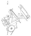
Figures 2-6 illustrate non-threshed crop portions or tailings are collected in atailings pan 59 and moved by atailings auger 60 to a circulatingchain elevator 62 within ahousing 63 which elevates the tailings to adischarge opening 64 by way of paddles 62a attached to an endless chain 62b (Figure 6 ). Such an elevator is known and is disclosed for example as elevator 54 inUS 5 497 605 Arethreshing apparatus 66 that comprises arethreshing rotor 68 driven in rotation within arethreshing cylinder 72. -
Rethreshing rotor 68 rotates withinrethreshing cylinder 72. Thecylinder 72 includes rasp bars 73 on an adjustable wall 74. There are no perforations in the walls of the cylinder. The rotor includes bars 75 that pass against the rasp bars 73. The rotor can be equipped with different bars depending on the nature of the crop being processed, including rasp bars for difficult threshing crops, swept back bars to allow material to be pushed against the stationary rasp bars for threshing while still allowing good material handling characteristics, or serrated bars for wet material movement. -
Gap 76 betweenrethreshing rotor 68 and the adjustable wall 74 can be selectively adjusted by moving wall 74 either towards or away fromrotor 68. Selectinggap 76 defines clearances betweenrotor 68 andhousing 72 for controlling the yield and throughput for rethreshing a particular crop. Rethreshing yield is increased by decreasinggap 76 so that more clean grain is separated from tailings. However, decreasinggap 76 to increase yield decreases throughput, since clearances are reduced. Thus,gap 76 should be set for particular crops to counterbalance throughput verses yield for rethreshing tailings. - As a further enhancement, a
deflector plate 84 can be provided within thehousing 72 which is effective to cause tailings to bypass therethreshing rotor 68 andrethreshing cylinder 72. Thedeflector plate 84 is shown in a first, rethreshing position marked 84a and a second, bypass position marked 84b. Rethreshing crop flow is thrown by the paddles ofelevator 62 through thedischarge opening 64 in the direction indicated by arrow marked "A" into therethreshing cylinder 72, and bypass crop flow is thrown downward into achute 92 in the direction indicated by arrow marked "B." - The
rotor 68 is driven on one axial end by apulley 93 driven by abelt 93a driven by the equipment drive power system of the combine on a near side of thecylinder 72. - The other axial end of the
rotor 68 drives apulley 94 that circulates a belt 94a, that drives a pulley 95 that drives the circulating chain 62b of the elevator 62 (FIG. 3 ). - Rethreshing crop flow "A" and/or bypass crop flow "B" exits the
cylinder 72 downward through thechute 92 to anauger 96. Theauger 96 includes atubular auger housing 98 and anauger screw 100. - The
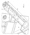
tubular auger housing 98 is arranged transversely across the cleaning system 26, particularly over the return pan 45. The auger housing includes a taperedslot formation 120 that has a far sidesmall width 122 increasing to a near sidemaximum width 124. In this way, the tailings conveyed by theauger screw 100 from thechute 92 will be evenly distributed from out of theslot formation 120 transversely across the return pan. - As an enhancement to the slotted design, plural external curved baffles 130 (only two shown in phantom) can be provided on the
auger housing 98 which can be slidably positioned and attached to close off areas of the slot formation to fine tune crop distribution on the return pan. Also, the retun pan can have baffles, vanes or distributors to further enhance distribution of the tailings delivered from theauger 96. - The
auger screw 100 is driven in rotation by a sprocket orpulley 140 located on its far side end that is driven by a belt or chain (not shown) from the equipment drive power system of the combine. - The invention allows for the tailings return auger 96 to distribute rethreshed tailings directly and in a controlled position and distribution onto the return pan 45 of the cleaning system to be reintroduced to the
sieves processing unit 24 onto the return pan 45. In this regard the rethreshed tailings need not be recirculated back to theprocessing unit 24, which avoids grain being circulated in an endless loop and allows for fine tuning of the harvesting operation.
Claims (5)
- A rethreshing system for a combine (10) having a cleaning system (26) including at least one sieve (46, 48), the retreshing system comprising:a tailings collection pan (59) for collecting tailings that do not pass through said sieve (46, 48);a tailings rethreshing mechanism receiving said tailings from said collection pan (59) and rethreshing said tailings;characterized by a distribution auger (96) arranged across said cleaning system (26) and operable to distribute rethreshed tailings on said cleaning system (26).
- The rethreshing system according to claim 1, wherein said cleaning system (26) includes a return pan (45) for distributing crop material onto said sieve (46) and said distribution auger (96) is arranged to substantially evenly distribute rethreshed tailings transversely across said return pan (45).
- The rethreshing system according to claim 1 or 2, wherein said distribution auger (96) comprises a tubular auger housing (98) having an entrance or receiving material to be conveyed, a closed end opposite said entrance, and a longitudinally elongated and tapered slot formation (120) through a sidewall of said tubular auger housing (98), said slot formation (120) having a small width (122) near said entrance to said tubular housing (98) and a wide width (124) near said closed end of said tubular housing (98).
- The rethreshing system according to one of claims 1 to 3, comprising:a tailings auger (60) arranged to convey tailings to one end of the tailings collection pan (45); andan elevator (62) arranged to receive the tailings from said tailings auger (60) and to deliver said tailings to said rethreshing mechanism; anda chute (92) that delivers rethreshed tailings from said rethreshing mechanism to said distribution auger (90).
- An agricultural combine (10), comprising:a threshing and separating processing unit (24);a cleaning system (26) comprising at least one sieve (46, 48) receiving crop material passing through said threshing and separating unit (24);a rethreshing mechanism according to one of the preceding claims.
Applications Claiming Priority (1)
| Application Number | Priority Date | Filing Date | Title |
|---|---|---|---|
| US11/982,417 US7934982B2 (en) | 2007-10-31 | 2007-10-31 | Tailings rethresher mechanical delivery to return pan |
Publications (3)
| Publication Number | Publication Date |
|---|---|
| EP2055178A2 true EP2055178A2 (en) | 2009-05-06 |
| EP2055178A3 EP2055178A3 (en) | 2009-10-28 |
| EP2055178B1 EP2055178B1 (en) | 2011-08-24 |
Family
ID=40296576
Family Applications (1)
| Application Number | Title | Priority Date | Filing Date |
|---|---|---|---|
| EP08162892A Active EP2055178B1 (en) | 2007-10-31 | 2008-08-25 | Rethreshing system for a combine |
Country Status (5)
| Country | Link |
|---|---|
| US (1) | US7934982B2 (en) |
| EP (1) | EP2055178B1 (en) |
| AR (1) | AR069117A1 (en) |
| BR (1) | BRPI0804341B1 (en) |
| RU (1) | RU2488263C2 (en) |
Cited By (8)
| Publication number | Priority date | Publication date | Assignee | Title |
|---|---|---|---|---|
| EP2064940B1 (en) * | 2007-11-29 | 2012-07-18 | Deere & Company | Tailings rethresher deflector |
| DE102011088543A1 (en) | 2011-12-14 | 2013-06-20 | Deere & Company | Combine harvesters for separation between crop grain and crop residue in processing process, has rethresher unit, which is arranged between threshing concave and cleaning unit for repeating threshing through threshing concave |
| DE102011088546A1 (en) | 2011-12-14 | 2013-06-20 | Deere & Company | Threshing concave assembly of combine harvester, has bars that are arranged in front portion and rear portion respectively, and are extended on side wall in axial direction |
| WO2015121725A1 (en) * | 2014-02-11 | 2015-08-20 | Agco Corporation | Air deflector for return pan of harvester cleaning shoe |
| EP2064941B1 (en) * | 2007-11-29 | 2019-05-08 | Deere & Company | Tailing Rethresher |
| EP3501259A1 (en) * | 2017-12-09 | 2019-06-26 | Deere & Company | Return pan for an agricultural combine |
| WO2019151981A1 (en) * | 2018-01-30 | 2019-08-08 | Tribine Industries Llc | Agricultural harvesting combine provided with bonus sieves |
| US20250221343A1 (en) * | 2024-01-08 | 2025-07-10 | Deere & Company | Active return tube and method of controlling same |
Families Citing this family (9)
| Publication number | Priority date | Publication date | Assignee | Title |
|---|---|---|---|---|
| US8313362B2 (en) * | 2009-04-16 | 2012-11-20 | Cnh America Llc | Agricultural combine with on-board baler and dust suppression capability |
| DE102012218742A1 (en) * | 2012-10-15 | 2014-04-17 | Deere & Company | Nachdrescheinrichtung for a combine harvester |
| BE1022661B1 (en) * | 2015-03-31 | 2016-06-29 | Cnh Industrial Belgium Nv | IMPROVEMENTS OF OR CONCERNING GRAIN CLEANERS FOR MOWING THREADERS |
| US9578806B2 (en) * | 2015-06-12 | 2017-02-28 | Cnh Industrial America Llc | Agricultural harvester header with retracting paddles for conveying crop material |
| US10045488B2 (en) * | 2016-08-01 | 2018-08-14 | Tribine Industries Llc | Bonus sieves and tailings return for an articulated agricultural harvesting combine |
| US10674671B2 (en) * | 2017-12-08 | 2020-06-09 | Cnh Industrial America Llc | Auxiliary processing system |
| US11369060B2 (en) * | 2018-02-19 | 2022-06-28 | Cnh Industrial America Llc | Removable auger trough |
| US12089535B2 (en) * | 2019-03-21 | 2024-09-17 | Cnh Industrial America Llc | Removable insert for a threshing rotor cage |
| US11147214B2 (en) * | 2019-06-26 | 2021-10-19 | Deere & Company | Combine with a pre-thresher |
Citations (11)
| Publication number | Priority date | Publication date | Assignee | Title |
|---|---|---|---|---|
| US4531528A (en) | 1983-03-07 | 1985-07-30 | Deere & Company | Cleaning shoe for a combine |
| DE4015950C1 (en) | 1990-05-18 | 1991-04-18 | Deere & Company, Moline, Ill., Us | Material conveyor in harvester - incorporates element extending into receiving chamber |
| DE4100844C2 (en) | 1991-01-14 | 1994-03-31 | Deere & Co | Conveyor of a harvester |
| US5445563A (en) | 1993-07-01 | 1995-08-29 | Deere & Company | Axial flow combine having a concentric threshing section and an eccentric separating section |
| US5498206A (en) | 1994-08-08 | 1996-03-12 | Deere & Company | Rethreshing rotor for grain combine |
| US5497605A (en) | 1994-11-15 | 1996-03-12 | Deere & Company | Header and feeder for a grain combine |
| US5688170A (en) | 1993-07-01 | 1997-11-18 | Deere & Company | Rotary combine having a concentric infeed section and eccentric threshing and separating sections |
| US20020128054A1 (en) | 2001-03-10 | 2002-09-12 | Deere & Company, A Delaware Corporation | Sieve for a harvester thresher |
| US6672957B2 (en) | 2002-03-28 | 2004-01-06 | Agco Corporation | Combine harvester cleaning apparatus |
| US20050164755A1 (en) | 2004-01-27 | 2005-07-28 | Deere & Company, A Delaware Corporation | Cleaning shoe spreaders |
| US7070498B2 (en) | 2003-07-29 | 2006-07-04 | Deere & Company | Frusto-conical drum infeed and threshing region for a combine rotor |
Family Cites Families (31)
| Publication number | Priority date | Publication date | Assignee | Title |
|---|---|---|---|---|
| US1502702A (en) * | 1923-10-20 | 1924-07-29 | Indiana Mfg Co | Grain-saving device for thrashing machines |
| US2309736A (en) * | 1941-05-29 | 1943-02-02 | Makin Melfred | Rethresher attachment for threshers |
| US2433162A (en) * | 1945-04-04 | 1947-12-23 | Allis Chalmers Mfg Co | Harvester-thresher |
| US2657801A (en) * | 1948-06-01 | 1953-11-03 | Leslie J Quilling | Watermelon crusher and seed separator |
| BE554331A (en) * | 1956-01-19 | |||
| US2893558A (en) * | 1957-08-14 | 1959-07-07 | Ezra J Zollinger | Chaffer screen feed for agricultural combine harvester |
| US3108064A (en) * | 1961-02-20 | 1963-10-22 | Massey Ferguson Ltd | Grain feeding attachment for hillside operation of a combine |
| US3247855A (en) * | 1962-03-13 | 1966-04-26 | Massey Ferguson Ltd | Auxiliary rethresher for a combine |
| US3373871A (en) * | 1965-04-07 | 1968-03-19 | Calvin J. Huether | Separating sieves for combines |
| US3482577A (en) * | 1967-06-21 | 1969-12-09 | Int Harvester Co | Tailings return |
| US3474937A (en) * | 1968-01-03 | 1969-10-28 | Intern Stock Food Corp | Fluent material dispenser with agitator and plural discharge assistants |
| US3581746A (en) * | 1968-05-01 | 1971-06-01 | Robert A Louks | Apparatus for distributing grain to a combine chaffer screen |
| US3463314A (en) * | 1968-05-13 | 1969-08-26 | Leon G Feterl | Grain cleaning mechanism |
| DE1918366A1 (en) * | 1969-04-11 | 1970-10-15 | Friedrich Wesemann | Overcoming threshing device for combine harvester, which is arranged on the extended shaft of the threshing drum, outside the combine harvester housing |
| GB1548381A (en) * | 1975-06-26 | 1979-07-11 | Clayson Nv | Harvesting machines |
| US4178944A (en) * | 1977-10-11 | 1979-12-18 | Allis-Chalmers Corporation | Tailings return for an axial flow combine |
| US4310004A (en) * | 1979-07-06 | 1982-01-12 | Sperry Corporation | Combine harvester rethresher |
| FR2460596B1 (en) * | 1979-07-06 | 1985-06-28 | Sperry Nv | CONVEYOR DEVICE FOR RECYCLING OTONS ON A COMBINE HARVESTER |
| US4424634A (en) * | 1981-06-19 | 1984-01-10 | Westelaken C | Modular column dryer for particulate material |
| US4470420A (en) * | 1983-06-23 | 1984-09-11 | Allis-Chalmers Corporation | Divertable tailings return |
| US4466447A (en) * | 1983-06-23 | 1984-08-21 | Allis-Chalmers Corporation | Tailings return to threshing section or to cleaning section |
| SU1400536A1 (en) * | 1985-06-10 | 1988-06-07 | Азово-Черноморский Институт Механизации Сельского Хозяйства | Straw collector for grain combine harvester |
| SU1384268A1 (en) * | 1986-10-14 | 1988-03-30 | Головное Специализированное Конструкторское Бюро По Машинам Для Уборки Зерновых Культур И Самоходным Шасси | Method of treatment of cereal crop heap and header of grain combine harvester |
| EP0467027A2 (en) * | 1990-05-18 | 1992-01-22 | Deere & Company | Conveyor for a harvester |
| US6537520B1 (en) * | 1998-03-31 | 2003-03-25 | Bristol-Myers Squibb Pharma Company | Pharmaceuticals for the imaging of angiogenic disorders |
| DE19912372C1 (en) * | 1999-03-19 | 2000-11-09 | Case Harvesting Sys Gmbh | Device for measuring the grain fraction in a return of a combine harvester |
| GB2356546A (en) * | 1999-11-26 | 2001-05-30 | Ford New Holland Nv | Threshing and separating unit for axial flow combines |
| US6458031B1 (en) * | 2000-01-18 | 2002-10-01 | Case Corporation | Cleaning system for a rotary combine |
| US6669558B1 (en) * | 2002-07-17 | 2003-12-30 | Case, Llc | Tailings conveyor housing |
| US7025673B2 (en) * | 2003-01-10 | 2006-04-11 | Cnh America Llc | Tailings conveyor system |
| US7381131B1 (en) * | 2006-07-19 | 2008-06-03 | Harpole Danny J | Extendable auger conveyor |
-
2007
- 2007-10-31 US US11/982,417 patent/US7934982B2/en active Active
-
2008
- 2008-08-25 EP EP08162892A patent/EP2055178B1/en active Active
- 2008-10-17 BR BRPI0804341A patent/BRPI0804341B1/en active IP Right Grant
- 2008-10-30 RU RU2008143122/13A patent/RU2488263C2/en not_active IP Right Cessation
- 2008-10-30 AR ARP080104750A patent/AR069117A1/en active IP Right Grant
Patent Citations (11)
| Publication number | Priority date | Publication date | Assignee | Title |
|---|---|---|---|---|
| US4531528A (en) | 1983-03-07 | 1985-07-30 | Deere & Company | Cleaning shoe for a combine |
| DE4015950C1 (en) | 1990-05-18 | 1991-04-18 | Deere & Company, Moline, Ill., Us | Material conveyor in harvester - incorporates element extending into receiving chamber |
| DE4100844C2 (en) | 1991-01-14 | 1994-03-31 | Deere & Co | Conveyor of a harvester |
| US5445563A (en) | 1993-07-01 | 1995-08-29 | Deere & Company | Axial flow combine having a concentric threshing section and an eccentric separating section |
| US5688170A (en) | 1993-07-01 | 1997-11-18 | Deere & Company | Rotary combine having a concentric infeed section and eccentric threshing and separating sections |
| US5498206A (en) | 1994-08-08 | 1996-03-12 | Deere & Company | Rethreshing rotor for grain combine |
| US5497605A (en) | 1994-11-15 | 1996-03-12 | Deere & Company | Header and feeder for a grain combine |
| US20020128054A1 (en) | 2001-03-10 | 2002-09-12 | Deere & Company, A Delaware Corporation | Sieve for a harvester thresher |
| US6672957B2 (en) | 2002-03-28 | 2004-01-06 | Agco Corporation | Combine harvester cleaning apparatus |
| US7070498B2 (en) | 2003-07-29 | 2006-07-04 | Deere & Company | Frusto-conical drum infeed and threshing region for a combine rotor |
| US20050164755A1 (en) | 2004-01-27 | 2005-07-28 | Deere & Company, A Delaware Corporation | Cleaning shoe spreaders |
Cited By (13)
| Publication number | Priority date | Publication date | Assignee | Title |
|---|---|---|---|---|
| EP2064940B1 (en) * | 2007-11-29 | 2012-07-18 | Deere & Company | Tailings rethresher deflector |
| EP2064941B1 (en) * | 2007-11-29 | 2019-05-08 | Deere & Company | Tailing Rethresher |
| DE102011088546B4 (en) | 2011-12-14 | 2024-11-14 | Deere & Company | combine harvester |
| DE102011088543A1 (en) | 2011-12-14 | 2013-06-20 | Deere & Company | Combine harvesters for separation between crop grain and crop residue in processing process, has rethresher unit, which is arranged between threshing concave and cleaning unit for repeating threshing through threshing concave |
| DE102011088546A1 (en) | 2011-12-14 | 2013-06-20 | Deere & Company | Threshing concave assembly of combine harvester, has bars that are arranged in front portion and rear portion respectively, and are extended on side wall in axial direction |
| BE1021334B1 (en) * | 2011-12-14 | 2015-10-30 | Deere & Company | COMBINE WITH A NACHDRESCHEINRICHTUNG ARRANGED BETWEEN THE DRESCHEINRICHTUNG AND CLEANING |
| DE102011088543B4 (en) | 2011-12-14 | 2024-11-14 | Deere & Company | Combine harvester with a post-threshing device arranged between the threshing device and the cleaning device |
| WO2015121725A1 (en) * | 2014-02-11 | 2015-08-20 | Agco Corporation | Air deflector for return pan of harvester cleaning shoe |
| US9986688B2 (en) | 2014-02-11 | 2018-06-05 | Agco Corporation | Air deflector for return pan of harvester cleaning shoe |
| US10791677B2 (en) | 2017-12-09 | 2020-10-06 | Deere & Company | Return pan for an agricultural combine |
| EP3501259A1 (en) * | 2017-12-09 | 2019-06-26 | Deere & Company | Return pan for an agricultural combine |
| WO2019151981A1 (en) * | 2018-01-30 | 2019-08-08 | Tribine Industries Llc | Agricultural harvesting combine provided with bonus sieves |
| US20250221343A1 (en) * | 2024-01-08 | 2025-07-10 | Deere & Company | Active return tube and method of controlling same |
Also Published As
| Publication number | Publication date |
|---|---|
| BRPI0804341A2 (en) | 2010-01-19 |
| AR069117A1 (en) | 2009-12-30 |
| RU2008143122A (en) | 2010-05-10 |
| RU2488263C2 (en) | 2013-07-27 |
| BRPI0804341B1 (en) | 2019-01-15 |
| US20090111545A1 (en) | 2009-04-30 |
| US7934982B2 (en) | 2011-05-03 |
| EP2055178B1 (en) | 2011-08-24 |
| EP2055178A3 (en) | 2009-10-28 |
Similar Documents
| Publication | Publication Date | Title |
|---|---|---|
| EP2055178B1 (en) | Rethreshing system for a combine | |
| US3645270A (en) | Axial flow threshing and separating unit creating an airflow along the grain pan | |
| EP2064941B1 (en) | Tailing Rethresher | |
| CA1132026A (en) | Rotary combine | |
| US3593719A (en) | Combine with three-stage separation | |
| EP1529434B1 (en) | System for positively discharging crop residue from a combine | |
| US3742686A (en) | Axial flow combine harvester | |
| CA2267724C (en) | Crop processing element for a rotary combine | |
| EP3018995B1 (en) | Cleaning assembly for a harvester | |
| CN114786469B (en) | Agricultural harvester including a threshing drum having a rasp bar with crop outlet gaps | |
| US4208858A (en) | Isolated pneumatic cleaning system | |
| EP2064940B1 (en) | Tailings rethresher deflector | |
| EP3232767B1 (en) | Crop processing apparatus in a combine harvester | |
| US6475082B2 (en) | Flap openings in a grain harvesting threshing and separation unit | |
| EP2111744B1 (en) | Combine clean grain elevator system | |
| US7396278B2 (en) | Cleaning shoe spreaders | |
| US11147214B2 (en) | Combine with a pre-thresher | |
| CN112547474A (en) | Rotary grain cleaner | |
| CN111713247B (en) | Agricultural harvester, threshing and separating system thereof and threshing performance adjusting method | |
| JP2001258375A (en) | Threshing machine sorting equipment |
Legal Events
| Date | Code | Title | Description |
|---|---|---|---|
| PUAI | Public reference made under article 153(3) epc to a published international application that has entered the european phase |
Free format text: ORIGINAL CODE: 0009012 |
|
| AK | Designated contracting states |
Kind code of ref document: A2 Designated state(s): AT BE BG CH CY CZ DE DK EE ES FI FR GB GR HR HU IE IS IT LI LT LU LV MC MT NL NO PL PT RO SE SI SK TR |
|
| AX | Request for extension of the european patent |
Extension state: AL BA MK RS |
|
| PUAL | Search report despatched |
Free format text: ORIGINAL CODE: 0009013 |
|
| AK | Designated contracting states |
Kind code of ref document: A3 Designated state(s): AT BE BG CH CY CZ DE DK EE ES FI FR GB GR HR HU IE IS IT LI LT LU LV MC MT NL NO PL PT RO SE SI SK TR |
|
| AX | Request for extension of the european patent |
Extension state: AL BA MK RS |
|
| 17P | Request for examination filed |
Effective date: 20100428 |
|
| AKX | Designation fees paid |
Designated state(s): BE DE DK IT PL SE |
|
| 17Q | First examination report despatched |
Effective date: 20100614 |
|
| GRAP | Despatch of communication of intention to grant a patent |
Free format text: ORIGINAL CODE: EPIDOSNIGR1 |
|
| GRAS | Grant fee paid |
Free format text: ORIGINAL CODE: EPIDOSNIGR3 |
|
| GRAA | (expected) grant |
Free format text: ORIGINAL CODE: 0009210 |
|
| AK | Designated contracting states |
Kind code of ref document: B1 Designated state(s): BE DE DK IT PL SE |
|
| REG | Reference to a national code |
Ref country code: DE Ref legal event code: R096 Ref document number: 602008009064 Country of ref document: DE Effective date: 20111117 |
|
| PG25 | Lapsed in a contracting state [announced via postgrant information from national office to epo] |
Ref country code: SE Free format text: LAPSE BECAUSE OF FAILURE TO SUBMIT A TRANSLATION OF THE DESCRIPTION OR TO PAY THE FEE WITHIN THE PRESCRIBED TIME-LIMIT Effective date: 20110824 |
|
| PG25 | Lapsed in a contracting state [announced via postgrant information from national office to epo] |
Ref country code: PL Free format text: LAPSE BECAUSE OF FAILURE TO SUBMIT A TRANSLATION OF THE DESCRIPTION OR TO PAY THE FEE WITHIN THE PRESCRIBED TIME-LIMIT Effective date: 20110824 |
|
| PG25 | Lapsed in a contracting state [announced via postgrant information from national office to epo] |
Ref country code: DK Free format text: LAPSE BECAUSE OF FAILURE TO SUBMIT A TRANSLATION OF THE DESCRIPTION OR TO PAY THE FEE WITHIN THE PRESCRIBED TIME-LIMIT Effective date: 20110824 |
|
| PLBE | No opposition filed within time limit |
Free format text: ORIGINAL CODE: 0009261 |
|
| STAA | Information on the status of an ep patent application or granted ep patent |
Free format text: STATUS: NO OPPOSITION FILED WITHIN TIME LIMIT |
|
| 26N | No opposition filed |
Effective date: 20120525 |
|
| REG | Reference to a national code |
Ref country code: DE Ref legal event code: R097 Ref document number: 602008009064 Country of ref document: DE Effective date: 20120525 |
|
| PGFP | Annual fee paid to national office [announced via postgrant information from national office to epo] |
Ref country code: IT Payment date: 20140823 Year of fee payment: 7 |
|
| PG25 | Lapsed in a contracting state [announced via postgrant information from national office to epo] |
Ref country code: IT Free format text: LAPSE BECAUSE OF NON-PAYMENT OF DUE FEES Effective date: 20150825 |
|
| PGFP | Annual fee paid to national office [announced via postgrant information from national office to epo] |
Ref country code: BE Payment date: 20240827 Year of fee payment: 17 |
|
| PGFP | Annual fee paid to national office [announced via postgrant information from national office to epo] |
Ref country code: DE Payment date: 20250721 Year of fee payment: 18 |