EP2055171A2 - Suspension system for a floating header on an agricultural implement - Google Patents
Suspension system for a floating header on an agricultural implement Download PDFInfo
- Publication number
- EP2055171A2 EP2055171A2 EP08153249A EP08153249A EP2055171A2 EP 2055171 A2 EP2055171 A2 EP 2055171A2 EP 08153249 A EP08153249 A EP 08153249A EP 08153249 A EP08153249 A EP 08153249A EP 2055171 A2 EP2055171 A2 EP 2055171A2
- Authority
- EP
- European Patent Office
- Prior art keywords
- hydraulic
- accumulator
- header
- cylinder
- hydraulic cylinder
- Prior art date
- Legal status (The legal status is an assumption and is not a legal conclusion. Google has not performed a legal analysis and makes no representation as to the accuracy of the status listed.)
- Granted
Links
Images




Classifications
-
- A—HUMAN NECESSITIES
- A01—AGRICULTURE; FORESTRY; ANIMAL HUSBANDRY; HUNTING; TRAPPING; FISHING
- A01D—HARVESTING; MOWING
- A01D34/00—Mowers; Mowing apparatus of harvesters
- A01D34/01—Mowers; Mowing apparatus of harvesters characterised by features relating to the type of cutting apparatus
- A01D34/412—Mowers; Mowing apparatus of harvesters characterised by features relating to the type of cutting apparatus having rotating cutters
- A01D34/63—Mowers; Mowing apparatus of harvesters characterised by features relating to the type of cutting apparatus having rotating cutters having cutters rotating about a vertical axis
- A01D34/64—Mowers; Mowing apparatus of harvesters characterised by features relating to the type of cutting apparatus having rotating cutters having cutters rotating about a vertical axis mounted on a vehicle, e.g. a tractor, or drawn by an animal or a vehicle
- A01D34/66—Mowers; Mowing apparatus of harvesters characterised by features relating to the type of cutting apparatus having rotating cutters having cutters rotating about a vertical axis mounted on a vehicle, e.g. a tractor, or drawn by an animal or a vehicle with two or more cutters
- A01D34/661—Mounting means
-
- A—HUMAN NECESSITIES
- A01—AGRICULTURE; FORESTRY; ANIMAL HUSBANDRY; HUNTING; TRAPPING; FISHING
- A01B—SOIL WORKING IN AGRICULTURE OR FORESTRY; PARTS, DETAILS, OR ACCESSORIES OF AGRICULTURAL MACHINES OR IMPLEMENTS, IN GENERAL
- A01B63/00—Lifting or adjusting devices or arrangements for agricultural machines or implements
- A01B63/14—Lifting or adjusting devices or arrangements for agricultural machines or implements for implements drawn by animals or tractors
- A01B63/24—Tools or tool-holders adjustable relatively to the frame
- A01B63/32—Tools or tool-holders adjustable relatively to the frame operated by hydraulic or pneumatic means without automatic control
Definitions
- the present invention relates generally to an agricultural implement, including a floating header. More particularly, the present invention relates to an improved suspension system for agricultural implements having one or more floating headers wherein the suspension hydraulic cylinders are also used to lift the header for transport.
- a three-point mounted mower with a suspension system is disclosed in U.S. Patent Application No. 5,417,042 .
- Disclosed in this application is an example of a mower suspension system with separate elements having a first and a second chamber and separate fluid inlets. These pairs are intended for different functions. One pair is used to lift to a transport position while the other pair is used to transfer oil during operation to suspend the header.
- U.S. Patent No. 6,085,501 Another example of a three-point mounted mower is disclosed in U.S. Patent No. 6,085,501 .
- This patent describes a machine where the frame is not lifted to raise the header to a transport position, but where there are effectively two separate cylinders, one to lift into transport, another to suspend the header.
- the patent describes separate hydraulic rams.
- the multiplicity of components for lifting and suspending a floating header on a fixed-frame agricultural implement increases complexity, cost, while decreasing reliability.
- a fixed-frame, towable implement comprising a floating header, a hydraulic circuit, the hydraulic circuit comprising a source of pressurized hydraulic fluid, at least one hydraulic cylinder, and a hydraulic accumulator, in which implement, for providing both lift and variable-height suspension of the floating header:
- the implement could be such that:
- the hydraulic accumulator could be pressurizable to the predetermined pressure by:
- the hydraulic accumulator could be pressurizable to the predetermined pressure by adding a gas to the hydraulic accumulator to increase a pressure therein to the predetermined pressure.
- the gas could be selected from the group consisting of: air, nitrogen, carbon dioxide, argon and helium.
- a method of providing both lift and variable-height suspension of a floating header on a fixed-frame, towed implement comprising a hydraulic circuit, the hydraulic circuit comprising a source of pressurized hydraulic fluid, at least one hydraulic cylinder, and a hydraulic accumulator, the method comprising:
- the present invention also comprises a method of suspending a floating header, a component of a fixed-frame, towed implement, the towed implement comprising a tongue to which a prime mover is attached, a frame, the floating header, a first hydraulic cylinder, and a hydraulic accumulator, the method comprising:
- the fixed-frame, towed implement additionally could comprise a valve, the method additionally comprising:
- the method could then additionally comprise:
- the fixed-frame, towed implement could additionally comprises a second hydraulic cylinder, the method additionally comprising:
- Operatively attaching the second end of the first hydraulic cylinder to the floating header could comprise:
- Said prime mover could be a tractor operatively attached to the tongue.
- the present invention also comprises apparatus for suspending a floating header on a fixed-frame, towed implement comprising:
- Such apparatus could additionally comprise a second hydraulic cylinder comprising a first port in hydraulic communication with the source of pressurized hydraulic fluid and a second port in communication with the first hydraulic accumulator port.
- the apparatus could additionally comprise a pivoting link comprising a first pivot connection, operatively, pivotally connected to the second end of the first hydraulic cylinder and second pivot connection, operatively, pivotally connected to the floating header of the towed implement.
- the following embodiments provide a suspension system for implements having a floating header.
- the suspension system shall permit the floating header to contact the ground with an appropriate pressure.
- Another object of this invention is to provide the suspension using the same hydraulic cylinders used to lift the floating header.
- rams in the lift/flotation cylinders of the suspension system are in compression as they raise the header.
- the ram of the lift/flotation cylinder is in tension as it lifts the floating header.
- a hydraulic accumulator is used to allow for changes in a hydraulic cylinders' extension during operation without the usual valve manipulation to achieve those position changes.
- a take-up cylinder is incorporated with lift/flotation cylinders and the hydraulic accumulator to raise and lower the header.
- the take-up cylinder When the take-up cylinder is fully retracted, the hydraulic accumulator and the lift/flotation cylinders have reached their greatest pressures, and the lift/flotation cylinders their full extension so the header is fully raised.
- a valve is then opened slightly to allow the hydraulic accumulator to depressurize and the take-up cylinder to extend somewhat with the header under the force of gravity.
- the valve is again closed. At this predetermined pressure, the header bears on the ground surface with the required force.
- a lift/flotation cylinder is connected to the hydraulic accumulator by its retract port, thereby raising a sub-frame by retraction.
- the process is the same as that given for the first embodiment.
- the agricultural mower to which the present invention is applied is a towed, trailed, or drawn mower. This is in contrast to a tractor-mounted mower. Towed mowers have different suspension needs than do mounted mowers, as towed mowers are supported by the ground, independent of the tractor.
- the present invention includes a system for suspending a header 6 from a fixed-frame agricultural mower using hydraulic cylinders 14 and an accumulator 40.
- a fixed-frame for the purposes of this document, including the claims, is herein defined as a frame that does not articulate linearly relative to a ground-engaging wheel axle.
- the header 6, in turn, supports a cutter bar 9.
- a fixed-frame, towed mower 1 is equipped with two one-way hydraulic suspension cylinders 14 located at the outer edges of the frame 15 and supporting the header 6 via pivoting links 42.
- the pitch control hydraulic cylinder 13 controls the orientation of the cutter bar 9 in relation to the ground, known as pitch, while the tongue swing cylinder 17 is used to control the orientation of the tongue 2 in relation to the frame 15.
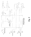
- Fig. 3 illustrates the hydraulic circuits, including the tongue circuit for controlling tongue swing cylinder 17, with a first tractor remote valve, and the header circuit for controlling the pitch control cylinder 13 and hydraulic suspension cylinders 14 with a second tractor remote valve.
- the header circuit provides three functions including control of header tilt, flotation, and lift.
- the flotation is provided by a hydro-pneumatic accumulator 40 used to exchange volumes of hydraulic fluid with the lift/flotation cylinders. This function is necessary when the header 6 is lowered, to allow the header 6 to follow the terrain, which occurs in the first embodiment when the lift/flotation cylinders 14 are retracted, wherein they cooperate with the accumulator 40.
- An upper pressurized gas chamber of the hydro-pneumatic accumulator 40 is under pressure. The pressure is shared with a lower chamber of the hydro-pneumatic accumulator 40, open to the hydraulic system.
- the header circuit also includes a take-up cylinder 41 and a valve 39.
- the take-up cylinder 41 controls the oil volume displaced for lifting and lowering the header.
- the valve 39 may be a manually operated ball valve that can be opened to allow flow, or closed to block flow.
- the valve 39 may alternatively be a solenoid operated valve capable of allowing flow when a solenoid is energized, and blocking flow then a solenoid is de-energized. The present invention is not limited to these types of valves. The functions of the valve 39 are described below.
- the towed mower 1 is hydraulically connected to a tractor (not shown) which provides a source of oil and is used to pump oil into the mower hydraulic systems to perform a variety of functions including:
- Charging of the lift/flotation circuit is necessary in order to insure that the take-up cylinder 41, a component of the mower hydraulic system, yet not strictly speaking a part of the suspension system, is properly filled with oil.
- the lift/flotation cylinders 14 and the tractor remote valve 87 can be directly connected or isolated by means of the valve 39.
- the valve 39 is set in a manifold at the base of the take-up cylinder 41.
- Charging is completed by allowing oil to flow through the valve 39, when opened, through the lines to the take-up cylinder 41, while first allowing air to escape at the take-up cylinder, and then to fully extend that cylinder, while also purging air out of the lines between the valve 39 and the lift/flotation cylinders 14 and the pressure gage 60.
- the tractor remote valve 87 is held in the position to force oil to the circuit until the lift/flotation cylinders 14 are in the extended position, and the header 6 is lifted to the transport position shown in Fig 2a .
- the valve 39 is locked, isolating the lift/flotation cylinders 14 from direct connection to the tractor hydraulics.
- the accumulator 40 is biased so as to act like a compressive spring by plumbing it to the extend port of the lift/flotation cylinders 14, most clearly shown in Figs. 3 and 4 .
- the tractor lifts the cutter bar 9 and pressurizes the accumulator 40.
- the tractor remote valve 87 is opened to the tractor hydraulic fluid reservoir so that it does not force oil through the remote valve 87.
- valve 39 is opened, either manually or electronically by the operator, to allow gravity to work against the accumulator 40 to lower the cutter bar 9 to the ground.
- the hydraulic system pressure can be viewed on a pressure gauge 60 so that the operator can bleed the valve 39 to allow the cutter bar 9 to press against the ground with appropriate pressure. This is done by pre-determining mower model-specific values for hydraulic system pressure at which the operator can close the valve 39 to maintain.
- the bias of the accumulator 40 to lift the cutter bar 9 keeps the cutter bar 9 from digging into the ground surface, yet is sufficiently small to allow gravity to press the cutter bar 9 against the surface and maintain continuous contact. This property of the cutter bar 9 is herein defined for the purposes of this document, including the claims, as "float.”
- Oil in the mower hydraulic system will constantly be seeking to occupy volume so as to obtain equilibrium pressures throughout the system. If the take-up cylinder valve 39 is locked, oil flow is restricted to flowing between the suspension cylinders 14 and the accumulator 40. Thus, with the valve 39 locked, the cutter bar 9 cannot be lifted or lowered via the tractor hydraulic system but only by the exchange of oil between the cylinders 14 and accumulator 40 as would be caused by variations in the force the ground exerts on the cutter bar 9 due to ground surface irregularity while mowing.
- the oil can flow between the cylinders 14 and the accumulator 40 to constantly maintain system pressure so that good contact between the cutter bar 9 and the ground is maintained.
- the suspension cylinders 14 are attached to a pivoting link 42 such that extending the cylinders 14 causes the header 6 to lift, while retracting the cylinder 14 lowers the header 6 to the ground.
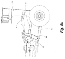
- a single one-way suspension cylinder 14 may be used as shown in Figs. 5a-5d .
- This cylinder 14 could pivotally connect, for instance, to a main frame 15 and a rear sub-frame 62 where the main frame 15 is fixed and the rear sub-frame 62 is allowed to lift, lower, or roll about an axis parallel to a direction of travel.
- Fig. 5a-5d This cylinder 14 could pivotally connect, for instance, to a main frame 15 and a rear sub-frame 62 where the main frame 15 is fixed and the rear sub-frame 62 is allowed to lift, lower, or roll about an axis parallel to a direction of travel.
- the rear sub-frame 62 maintains its orientation to the ground by a four-bar linkage comprising an upper link set 12 and a lower link set 11.
- the four-bar linkage is described more fully in U.S. Patent Application No. 11/927,866, filed October 30, 2007 and the co-pending European application filed under our Ref. 69310 .
- the rear sub-frame 62 is pivotally attached to a front sub-frame 10, to which the header 6 is ultimately attached.
- the rear sub-frame 62 is a link within the four-bar linkage, and the orientation of the sub-frame 62 is dictated thereby.
- the front sub-frame 10 may be permitted to pivot relative to the rear sub-frame 62 in order to orient the header 6 in an appropriate position for operation or transport.
- Swing arm cylinders 65 are provided on both sides of the agricultural mower 1 to pivot the tool bars 9 relative to the front sub-frame 10.
- the hydraulic system works by the same principles as in the first embodiment.
- the single cylinder 14 attached to the mower 1 as stated is configured to lift the sub-frame 10, 62 by retracting and to lower the sub-frame 10, 62 by extending.
- the accumulator 40 is plumbed to the retract port of the cylinder 14, as clearly illustrated in Figs. 5c and 5d .
- the pressure to the mower hydraulic system may be provided from the gas side of the accumulator 40. Pressurized air, nitrogen, carbon dioxide, argon, helium, or any other appropriate gas may be used to effect this pressurization.
- inventions of the novel suspension system herein described may be utilized for any implement making use of a floating header.
- the invention is not intended to be limited to agricultural mowers.
Landscapes
- Life Sciences & Earth Sciences (AREA)
- Environmental Sciences (AREA)
- Zoology (AREA)
- Engineering & Computer Science (AREA)
- Mechanical Engineering (AREA)
- Soil Sciences (AREA)
- Harvester Elements (AREA)
- Agricultural Machines (AREA)
Abstract
Description
- The present invention relates generally to an agricultural implement, including a floating header. More particularly, the present invention relates to an improved suspension system for agricultural implements having one or more floating headers wherein the suspension hydraulic cylinders are also used to lift the header for transport.
- A three-point mounted mower with a suspension system is disclosed in
U.S. Patent Application No. 5,417,042 . Disclosed in this application is an example of a mower suspension system with separate elements having a first and a second chamber and separate fluid inlets. These pairs are intended for different functions. One pair is used to lift to a transport position while the other pair is used to transfer oil during operation to suspend the header. - Another example of a three-point mounted mower is disclosed in
U.S. Patent No. 6,085,501 . This patent describes a machine where the frame is not lifted to raise the header to a transport position, but where there are effectively two separate cylinders, one to lift into transport, another to suspend the header. The patent describes separate hydraulic rams. - An example of a typical suspension for a trailed mower or mower conditioner is disclosed in
U.S. Patent Application No. 6,055,800 , wherein a cylinder lifts the frame and header to a transport position, while a spring provides a lift force to suspend the header in working position. - The multiplicity of components for lifting and suspending a floating header on a fixed-frame agricultural implement increases complexity, cost, while decreasing reliability.
- There is, therefore, a need for a method and apparatus for both lifting and providing suspension for a floating header on a fixed-frame agricultural implement such as a mower.
- According to the present invention from one aspect, there is provided a fixed-frame, towable implement, the implement comprising a floating header, a hydraulic circuit, the hydraulic circuit comprising a source of pressurized hydraulic fluid, at least one hydraulic cylinder, and a hydraulic accumulator, in which implement, for providing both lift and variable-height suspension of the floating header:
- (a) the hydraulic accumulator is pressurizable to a predetermined pressure;
- (b) the at least one hydraulic cylinder is placeable in hydraulic communication with the hydraulic accumulator;
- (c) at least a portion of a weight of the floating header is supportable on the fixed-frame, towed implement with the at least one hydraulic cylinder while the at least one hydraulic cylinder is in hydraulic communication with the hydraulic accumulator;
- (d) hydraulic fluid is exchangeable between the at least one hydraulic cylinder and the hydraulic accumulator to maintain a support of the header at varying header heights;
- (e) the at least one hydraulic cylinder is removable from hydraulic communication with the hydraulic accumulator; and
- (f) the floating header is liftable on the fixed-frame, towed implement with the at least one hydraulic cylinder while the at least one hydraulic cylinder is not in hydraulic communication with the hydraulic accumulator.
- The implement could be such that:
- (a) the hydraulic accumulator is placeable in hydraulic communication with the source of pressurized hydraulic fluid; and
- (b) the hydraulic circuit is completely fillable with oil.
- The hydraulic accumulator could be pressurizable to the predetermined pressure by:
- (a) placing the at least one hydraulic cylinder in hydraulic communication with the source of pressurized hydraulic fluid;
- (b) lifting the floating header by pressurizing the hydraulic circuit to move a ram of the at least one hydraulic cylinder while simultaneously pressurizing the hydraulic accumulator; and
- (c) reducing a pressure in the hydraulic accumulator to a predetermined value of pressure, thereby reducing a pressure to the at least one hydraulic cylinder.
- The hydraulic accumulator could be pressurizable to the predetermined pressure by adding a gas to the hydraulic accumulator to increase a pressure therein to the predetermined pressure.
- The gas could be selected from the group consisting of: air, nitrogen, carbon dioxide, argon and helium.
- According to the present invention from another aspect, there is provided a method of providing both lift and variable-height suspension of a floating header on a fixed-frame, towed implement, the implement comprising a hydraulic circuit, the hydraulic circuit comprising a source of pressurized hydraulic fluid, at least one hydraulic cylinder, and a hydraulic accumulator, the method comprising:
- (a) pressurizing the hydraulic accumulator to a predetermined pressure;
- (b) placing the at least one hydraulic cylinder in hydraulic communication with the hydraulic accumulator;
- (c) supporting at least a portion of a weight of the floating header on the fixed-frame, towed implement with the at least one hydraulic cylinder while the at least one hydraulic cylinder is in hydraulic communication with the hydraulic accumulator;
- (d) exchanging hydraulic fluid between the at least one hydraulic cylinder and the hydraulic accumulator to maintain a support of the header at varying header heights;
- (e) removing the at least one hydraulic cylinder from hydraulic communication with the hydraulic accumulator; and
- (f) lifting the floating header on the fixed-frame, towed implement with the at least one hydraulic cylinder while the at least one hydraulic cylinder is not in hydraulic communication with the hydraulic accumulator.
- The present invention also comprises a method of suspending a floating header, a component of a fixed-frame, towed implement, the towed implement comprising a tongue to which a prime mover is attached, a frame, the floating header, a first hydraulic cylinder, and a hydraulic accumulator, the method comprising:
- (a) operatively attaching a first end of the first hydraulic cylinder to the frame;
- (b) operatively attaching a second end of the first hydraulic cylinder to the floating header;
- (c) lifting the floating header by pressurizing a hydraulic system to move a ram of the first hydraulic cylinder while simultaneously pressurizing the hydraulic accumulator;
- (d) reducing a pressure in the hydraulic accumulator to a predetermined value of pressure, thereby reducing a pressure to the first hydraulic cylinder;
- (e) lowering the floating header of the fixed-frame, towed implement to a supporting surface while reducing the pressure in the hydraulic accumulator; and
- (f) suspending a portion of the floating header of the fixed-frame, towed implement with the first hydraulic cylinder, thereby allowing said floating header to float.
- In such a method the fixed-frame, towed implement additionally could comprise a valve, the method additionally comprising:
- (a) hydraulically connecting a first port of the valve to a source of pressurized hydraulic fluid;
- (b) hydraulically connecting a second port of the valve to a first port of the hydraulic accumulator; and
- (c) hydraulically connecting a second port of the hydraulic accumulator to a port of the first hydraulic cylinder.
- The method could then additionally comprise:
- (a) opening the valve to a throughflow of hydraulic fluid;
- (b) providing high pressure hydraulic fluid from the source of pressurized hydraulic fluid to the first port of the valve;
- (c) permitting the ram of the first hydraulic cylinder to move to position the header to a raised position;
- (d) closing the valve to the throughflow of hydraulic fluid;
- (e) reducing a pressure from the source of pressurized hydraulic fluid to the first port of the valve;
- (f) reopening the valve to the throughflow of hydraulic fluid until the pressure in the hydraulic accumulator reaches the predetermined value; and
- (g) closing the valve to the throughflow of hydraulic fluid.
- The fixed-frame, towed implement could additionally comprises a second hydraulic cylinder, the method additionally comprising:
- (a) hydraulically connecting a first port of the second hydraulic cylinder to the source of pressurized hydraulic fluid; and
- (b) hydraulically connecting a second port of the second hydraulic cylinder to the first port of the hydraulic accumulator.
- Operatively attaching the second end of the first hydraulic cylinder to the floating header could comprise:
- (a) operatively, pivotally attaching the second end of the first hydraulic cylinder to a first pivot of a pivoting link; and
- (b) operatively, pivotally attaching a second pivot of a pivoting link to the floating header.
- Said prime mover could be a tractor operatively attached to the tongue.
- The present invention also comprises apparatus for suspending a floating header on a fixed-frame, towed implement comprising:
- (a) a fixed, towed vehicle frame, unarticulated relative to a ground-engaging wheel axle;
- (b) a source of pressurized hydraulic fluid comprising a first valve;
- (c) a second valve comprising a first valve port in hydraulic communication with the source of pressurized hydraulic fluid and a second valve port;
- (d) a hydraulic accumulator comprising a first hydraulic accumulator port in hydraulic communication with the second valve port and a second hydraulic accumulator port; and
- (e) a first hydraulic cylinder comprising a first end operatively attached to the towed vehicle frame, a second end operatively attached to the floating header, and a port in communication with the second hydraulic accumulator port such that the hydraulic accumulator may be removed from communication with the source of pressurized hydraulic fluid when the second valve is closed, the first hydraulic cylinder used to provide lift and suspension to the floating header.
- Such apparatus could additionally comprise a second hydraulic cylinder comprising a first port in hydraulic communication with the source of pressurized hydraulic fluid and a second port in communication with the first hydraulic accumulator port.
- The apparatus could additionally comprise a pivoting link comprising a first pivot connection, operatively, pivotally connected to the second end of the first hydraulic cylinder and second pivot connection, operatively, pivotally connected to the floating header of the towed implement.
- The following embodiments provide a suspension system for implements having a floating header. The suspension system shall permit the floating header to contact the ground with an appropriate pressure. Another object of this invention is to provide the suspension using the same hydraulic cylinders used to lift the floating header.
- In a first embodiment of the present invention, rams in the lift/flotation cylinders of the suspension system are in compression as they raise the header. In a second embodiment of this invention, the ram of the lift/flotation cylinder is in tension as it lifts the floating header.
- In both embodiments, a hydraulic accumulator is used to allow for changes in a hydraulic cylinders' extension during operation without the usual valve manipulation to achieve those position changes.
- A take-up cylinder is incorporated with lift/flotation cylinders and the hydraulic accumulator to raise and lower the header. When the take-up cylinder is fully retracted, the hydraulic accumulator and the lift/flotation cylinders have reached their greatest pressures, and the lift/flotation cylinders their full extension so the header is fully raised.
- A valve is then opened slightly to allow the hydraulic accumulator to depressurize and the take-up cylinder to extend somewhat with the header under the force of gravity. When a predetermined pressure is achieved in the hydraulic accumulator, the valve is again closed. At this predetermined pressure, the header bears on the ground surface with the required force.
- In the second embodiment, a lift/flotation cylinder is connected to the hydraulic accumulator by its retract port, thereby raising a sub-frame by retraction. The process is the same as that given for the first embodiment.
- Other objects, advantages and novel features of the present invention will become apparent from the following detailed description of the invention when considered in conjunction with the accompanying drawings.
-
-
Fig. 1 is a perspective view of a towed agricultural mower having two hydraulic suspension cylinders mounted on the outer edges wherein the header is in a raised position; -
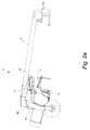
Fig. 2a is a first side elevation view of the agricultural mower with an accumulator also visible; -
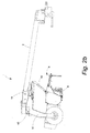
Fig. 2b is a second side elevation view of the agricultural mower with the header in a lowered position; -
Fig. 3 is a schematic representation of the mower hydraulic system; -
Fig. 4 is an exploded view of the hydraulic circuit in the embodiment ofFig. 1 ; -
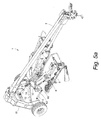
Fig. 5a is an isometric view of a mower in a transport configuration in an alternative embodiment as used on a multi-frame mower having the main frame and sub-frame connected by a single, one-way suspension cylinder; -
Fig. 5b is a side elevation view of the rear of the mower in the alternative embodiment shown inFig. 5a ; -
Fig. 5c provides a visual layout of the hydraulic circuit in the alternative embodiment as inFig. 5a ; and -
Fig. 5d is a schematic representation of the alternative embodiment of the mower hydraulic system. - The agricultural mower to which the present invention is applied is a towed, trailed, or drawn mower. This is in contrast to a tractor-mounted mower. Towed mowers have different suspension needs than do mounted mowers, as towed mowers are supported by the ground, independent of the tractor.
- Referring now to the drawings wherein like reference numerals correspond to the same or similar parts throughout the drawings, the present invention includes a system for suspending a header 6 from a fixed-frame agricultural mower using
hydraulic cylinders 14 and anaccumulator 40. (A fixed-frame, for the purposes of this document, including the claims, is herein defined as a frame that does not articulate linearly relative to a ground-engaging wheel axle.) The header 6, in turn, supports acutter bar 9. In a first embodiment, shown inFigs. 1-4 , a fixed-frame, towedmower 1 is equipped with two one-wayhydraulic suspension cylinders 14 located at the outer edges of theframe 15 and supporting the header 6 via pivotinglinks 42. The pitch controlhydraulic cylinder 13 controls the orientation of thecutter bar 9 in relation to the ground, known as pitch, while thetongue swing cylinder 17 is used to control the orientation of thetongue 2 in relation to theframe 15. -
Fig. 3 illustrates the hydraulic circuits, including the tongue circuit for controllingtongue swing cylinder 17, with a first tractor remote valve, and the header circuit for controlling thepitch control cylinder 13 andhydraulic suspension cylinders 14 with a second tractor remote valve. The header circuit provides three functions including control of header tilt, flotation, and lift. The flotation is provided by a hydro-pneumatic accumulator 40 used to exchange volumes of hydraulic fluid with the lift/flotation cylinders. This function is necessary when the header 6 is lowered, to allow the header 6 to follow the terrain, which occurs in the first embodiment when the lift/flotation cylinders 14 are retracted, wherein they cooperate with theaccumulator 40. An upper pressurized gas chamber of the hydro-pneumatic accumulator 40 is under pressure. The pressure is shared with a lower chamber of the hydro-pneumatic accumulator 40, open to the hydraulic system. - The header circuit also includes a take-up
cylinder 41 and avalve 39. The take-upcylinder 41 controls the oil volume displaced for lifting and lowering the header. Thevalve 39 may be a manually operated ball valve that can be opened to allow flow, or closed to block flow. Thevalve 39 may alternatively be a solenoid operated valve capable of allowing flow when a solenoid is energized, and blocking flow then a solenoid is de-energized. The present invention is not limited to these types of valves. The functions of thevalve 39 are described below. - In operation the towed
mower 1 is hydraulically connected to a tractor (not shown) which provides a source of oil and is used to pump oil into the mower hydraulic systems to perform a variety of functions including: - 1) to control the position of the
mower 1 relative to the tractor, thecylinder 17, as controlled by the first tractorremote valve 85 is extended or retracted, thereby changing the orientation of thetongue 2 relative to theframe 15 ; - 2) to control the position of the header 6 relative to the ground, the second tractor
remote valve 87 is moved to one extreme position which will cause the header 6 to lift, and when moved to the other extreme position will cause the header 6 to lower, and when left in the middle position will hold the header 6 in a set position; - 3) charging the lift/flotation circuit.
- Charging of the lift/flotation circuit is necessary in order to insure that the take-up
cylinder 41, a component of the mower hydraulic system, yet not strictly speaking a part of the suspension system, is properly filled with oil. The lift/flotation cylinders 14 and the tractorremote valve 87 can be directly connected or isolated by means of thevalve 39. In the first embodiment, as illustrated inFig. 4 , thevalve 39 is set in a manifold at the base of the take-upcylinder 41. Charging is completed by allowing oil to flow through thevalve 39, when opened, through the lines to the take-upcylinder 41, while first allowing air to escape at the take-up cylinder, and then to fully extend that cylinder, while also purging air out of the lines between thevalve 39 and the lift/flotation cylinders 14 and thepressure gage 60. The tractorremote valve 87 is held in the position to force oil to the circuit until the lift/flotation cylinders 14 are in the extended position, and the header 6 is lifted to the transport position shown inFig 2a . - After this first step of the charging procedure, the
valve 39 is locked, isolating the lift/flotation cylinders 14 from direct connection to the tractor hydraulics. In the present embodiment for a fixed-frame mower 1 as inFigs. 1 ,2a and2b , theaccumulator 40 is biased so as to act like a compressive spring by plumbing it to the extend port of the lift/flotation cylinders 14, most clearly shown inFigs. 3 and4 . Thus, during this first step of the charging procedure, the tractor lifts thecutter bar 9 and pressurizes theaccumulator 40. To complete the charging procedure the tractorremote valve 87 is opened to the tractor hydraulic fluid reservoir so that it does not force oil through theremote valve 87. This allows the oil to flow from the take-upcylinder 41 to the tractor hydraulic reservoir. Then thevalve 39 is opened, either manually or electronically by the operator, to allow gravity to work against theaccumulator 40 to lower thecutter bar 9 to the ground. The hydraulic system pressure can be viewed on apressure gauge 60 so that the operator can bleed thevalve 39 to allow thecutter bar 9 to press against the ground with appropriate pressure. This is done by pre-determining mower model-specific values for hydraulic system pressure at which the operator can close thevalve 39 to maintain. The bias of theaccumulator 40 to lift thecutter bar 9 keeps thecutter bar 9 from digging into the ground surface, yet is sufficiently small to allow gravity to press thecutter bar 9 against the surface and maintain continuous contact. This property of thecutter bar 9 is herein defined for the purposes of this document, including the claims, as "float." - Oil in the mower hydraulic system will constantly be seeking to occupy volume so as to obtain equilibrium pressures throughout the system. If the take-up
cylinder valve 39 is locked, oil flow is restricted to flowing between thesuspension cylinders 14 and theaccumulator 40. Thus, with thevalve 39 locked, thecutter bar 9 cannot be lifted or lowered via the tractor hydraulic system but only by the exchange of oil between thecylinders 14 andaccumulator 40 as would be caused by variations in the force the ground exerts on thecutter bar 9 due to ground surface irregularity while mowing. - As the mower passes over uneven ground, the ground exerts changing forces on the cutter bar(s) 9. The oil can flow between the
cylinders 14 and theaccumulator 40 to constantly maintain system pressure so that good contact between thecutter bar 9 and the ground is maintained. - In the first embodiment for a fixed-frame mower, the
suspension cylinders 14 are attached to a pivotinglink 42 such that extending thecylinders 14 causes the header 6 to lift, while retracting thecylinder 14 lowers the header 6 to the ground. In an alternative embodiment, valuable to mowers which may have separate configurations for transport and mowing, a single one-way suspension cylinder 14 may be used as shown inFigs. 5a-5d . Thiscylinder 14 could pivotally connect, for instance, to amain frame 15 and arear sub-frame 62 where themain frame 15 is fixed and therear sub-frame 62 is allowed to lift, lower, or roll about an axis parallel to a direction of travel. InFig. 5a , therear sub-frame 62 maintains its orientation to the ground by a four-bar linkage comprising an upper link set 12 and a lower link set 11. The four-bar linkage is described more fully inU.S. Patent Application No. 11/927,866, filed October 30, 2007 69310 - The
rear sub-frame 62 is pivotally attached to afront sub-frame 10, to which the header 6 is ultimately attached. Therear sub-frame 62 is a link within the four-bar linkage, and the orientation of thesub-frame 62 is dictated thereby. Thefront sub-frame 10 may be permitted to pivot relative to therear sub-frame 62 in order to orient the header 6 in an appropriate position for operation or transport. -
Swing arm cylinders 65 are provided on both sides of theagricultural mower 1 to pivot the tool bars 9 relative to thefront sub-frame 10. - In this second embodiment, the hydraulic system works by the same principles as in the first embodiment. However, the
single cylinder 14 attached to themower 1 as stated is configured to lift thesub-frame sub-frame accumulator 40 is plumbed to the retract port of thecylinder 14, as clearly illustrated inFigs. 5c and5d . - Operational Process (either embodiment):
- 1) Open the take-up
valve 39. - 2) Using the tractor as the power source, pressurize the mower hydraulic system. The sub-frame/header 6 will rise to a maximum height due to full retraction of the take-up
cylinder 41 and to fully stroking thecylinders 14. - 3) Close the take-up
valve 39. - 4) Put the tractor in float.
- 5) Crack the
valve 39 slowly to bleed excess pressure until the appropriate pressure is read from the gauge. The appropriate pressure will be established for each individual towedmower 1 model on which the present invention is incorporated. - 6) Lock the
valve 39 at an appropriate pressure. The cutter bars 9 will contact the ground with the hydraulic suspension of the present invention giving it the appropriate amount of contact pressure. Themower 1 is operational. - As an alternative to step 2, using the tractor as the power source, the pressure to the mower hydraulic system may be provided from the gas side of the
accumulator 40. Pressurized air, nitrogen, carbon dioxide, argon, helium, or any other appropriate gas may be used to effect this pressurization. - The embodiments of the novel suspension system herein described may be utilized for any implement making use of a floating header. The invention is not intended to be limited to agricultural mowers.
- The above embodiments are the preferred embodiments, but this invention is not limited thereto. It is, therefore, apparent that many modifications and variations of the present invention are possible in light of the above teachings. It is, therefore, to be understood that within the scope of the appended claims, the invention may be practiced otherwise than as specifically described.
Claims (9)
- A fixed-frame, towable implement, the implement comprising a floating header and a hydraulic circuit, the hydraulic circuit comprising a source of pressurized hydraulic fluid, at least one hydraulic cylinder and a hydraulic accumulator, in which implement, for providing both lift and variable-height suspension of the floating header:(a) the hydraulic accumulator is pressurizable to a predetermined pressure;(b) the at least one hydraulic cylinder is placeable in hydraulic communication with the hydraulic accumulator;(c) at least a portion of a weight of the floating header is supportable on the fixed-frame, towed implement with the at least one hydraulic cylinder while the at least one hydraulic cylinder is in hydraulic communication with the hydraulic accumulator;(d) hydraulic fluid is exchangeable between the at least one hydraulic cylinder and the hydraulic accumulator to maintain a support of the header at varying header heights;(e) the at least one hydraulic cylinder is removable from hydraulic communication with the hydraulic accumulator; and(f) the floating header is liftable on the fixed-frame, towed implement with the at least one hydraulic cylinder while the at least one hydraulic cylinder is not in hydraulic communication with the hydraulic accumulator.
- An implement according to claim 9, wherein:(a) the hydraulic accumulator is placeable in hydraulic communication with the source of pressurized hydraulic fluid; and(b) the hydraulic circuit is completely fillable with oil.
- An implement according to claim 1 or 2, wherein the hydraulic accumulator is pressurizable to the predetermined pressure by:(a) placing the at least one hydraulic cylinder in hydraulic communication with the source of pressurized hydraulic fluid;(b) lifting the floating header by pressurizing the hydraulic circuit to move a ram of the at least one hydraulic cylinder while simultaneously pressurizing the hydraulic accumulator; and(c) reducing a pressure in the hydraulic accumulator to a predetermined value of pressure, thereby reducing a pressure to the at least one hydraulic cylinder.
- An implement according to claim 1 or 2, wherein the hydraulic accumulator is pressurizable to the predetermined pressure by adding a gas to the hydraulic accumulator to increase a pressure therein to the predetermined pressure.
- A method of providing both lift and variable-height suspension of a floating header on a fixed-frame, towed implement, the implement comprising a hydraulic circuit, the hydraulic circuit comprising a source of pressurized hydraulic fluid, at least one hydraulic cylinder, and a hydraulic accumulator, the method comprising:(a) pressurizing the hydraulic accumulator to a predetermined pressure;(b) placing the at least one hydraulic cylinder in hydraulic communication with the hydraulic accumulator;(c) supporting at least a portion of a weight of the floating header on the fixed-frame, towed implement with the at least one hydraulic cylinder while the at least one hydraulic cylinder is in hydraulic communication with the hydraulic accumulator;(d) exchanging hydraulic fluid between the at least one hydraulic cylinder and the hydraulic accumulator to maintain a support of the header at varying header heights;(e) removing the at least one hydraulic cylinder from hydraulic communication with the hydraulic accumulator; and(f) lifting the floating header on the fixed-frame, towed implement with the at least one hydraulic cylinder while the at least one hydraulic cylinder is not in hydraulic communication with the hydraulic accumulator.
- A method according to claim 5 additionally comprising:(a) placing the hydraulic accumulator in hydraulic communication with the source of pressurized hydraulic fluid; and(b) allowing the hydraulic circuit to completely fill with oil.
- A method according to claim 5 or 6, wherein pressurizing the hydraulic accumulator to the predetermined pressure comprises:(a) placing the at least one hydraulic cylinder in hydraulic communication with the source of pressurized hydraulic fluid;(b) lifting the floating header by pressurizing the hydraulic circuit to move a ram of the at least one hydraulic cylinder while simultaneously pressurizing the hydraulic accumulator; and(c) reducing a pressure in the hydraulic accumulator to a predetermined value of pressure, thereby reducing a pressure to the at least one hydraulic cylinder.
- A method according to claim 5 or 6, wherein pressurizing the hydraulic accumulator to predetermined pressure comprises adding a gas to the hydraulic accumulator to increase a pressure therein to the predetermined pressure.
- A method according to claim 8, wherein adding a gas comprises adding a gas selected from the group consisting of: air, nitrogen, carbon dioxide, argon and helium.
Applications Claiming Priority (1)
| Application Number | Priority Date | Filing Date | Title |
|---|---|---|---|
| US11/928,010 US7596935B2 (en) | 2007-10-30 | 2007-10-30 | Suspension system for a floating header on an agricultural implement |
Publications (3)
| Publication Number | Publication Date |
|---|---|
| EP2055171A2 true EP2055171A2 (en) | 2009-05-06 |
| EP2055171A3 EP2055171A3 (en) | 2009-10-21 |
| EP2055171B1 EP2055171B1 (en) | 2013-12-18 |
Family
ID=40297024
Family Applications (1)
| Application Number | Title | Priority Date | Filing Date |
|---|---|---|---|
| EP08153249.1A Ceased EP2055171B1 (en) | 2007-10-30 | 2008-03-25 | Suspension system for a floating header on an agricultural implement |
Country Status (2)
| Country | Link |
|---|---|
| US (1) | US7596935B2 (en) |
| EP (1) | EP2055171B1 (en) |
Cited By (3)
| Publication number | Priority date | Publication date | Assignee | Title |
|---|---|---|---|---|
| WO2012099459A1 (en) * | 2011-01-17 | 2012-07-26 | Forage Innovations B.V. | An apparatus for suspending a rake wheel |
| ES2548105R1 (en) * | 2014-04-11 | 2015-11-13 | Diego ARCE GARCIA | Collection and transport system of a rake for rake of several locks in one, floating, with folding head, attachable to baler |
| NL2014567A (en) * | 2015-02-24 | 2016-10-10 | Forage Innovations Bv | Hydraulic balancing of independently loaded suspension cylinders in an implement. |
Families Citing this family (16)
| Publication number | Priority date | Publication date | Assignee | Title |
|---|---|---|---|---|
| US7726109B2 (en) | 2007-10-30 | 2010-06-01 | Vermeer Manufacturing Co. | Four-bar linkage for suspending a header for an agricultural implement |
| US8079204B2 (en) * | 2008-09-22 | 2011-12-20 | Deere & Company | Feeder house twist dampening system |
| NL1037078C2 (en) * | 2009-06-26 | 2010-12-28 | Lely Patent Nv | AGRICULTURAL MACHINE. |
| US8261521B2 (en) * | 2009-08-31 | 2012-09-11 | Vermeer Manufacturing Company | Self-leveling four-bar linkage for suspending a header of an agricultural implement |
| US8056307B2 (en) * | 2009-10-05 | 2011-11-15 | Cnh America Llc | Mower cutterbar |
| NL1037612C2 (en) * | 2010-01-05 | 2011-07-06 | Lely Patent Nv | AGRICULTURAL ESTABLISHMENT WITH ACCUMULATOR SUSPENSION. |
| US8528308B2 (en) * | 2010-01-19 | 2013-09-10 | Cnh America, Llc | Disc mower with folding wing frame |
| US8028505B1 (en) | 2010-08-26 | 2011-10-04 | Cnh America Llc | Telescoping flail mower and method of operation |
| FR2974270B1 (en) * | 2011-04-21 | 2014-04-04 | Kuhn Sa | AGRICULTURAL MACHINE WITH AN IMPROVED FOLDING DEVICE |
| DK2656716T3 (en) | 2012-04-26 | 2019-09-16 | Macdon Ind Ltd | Transport system for harvester-type harvester, where the machine remains balanced on transport wheels and coupling device when the transport system is used |
| US9258941B2 (en) * | 2012-11-19 | 2016-02-16 | Macdon Industries Ltd. | Rotary crop harvesting machine with cutter bar tilt control |
| CA2866046C (en) * | 2013-12-11 | 2018-06-19 | Cnh Industrial Canada, Ltd. | Apparatus and method for air removal in tillage implements using three way valves |
| US10517215B2 (en) * | 2017-10-12 | 2019-12-31 | Deere & Company | Roll center for attachment frame control arms |
| TWI665107B (en) * | 2017-12-12 | 2019-07-11 | 財團法人工業技術研究院 | Mobile vehicle, ground treating equipment and orientation adjusting method thereof |
| US11191213B2 (en) * | 2019-05-09 | 2021-12-07 | Cnh Industrial America Llc | Floatation adjustment array for harvester and methods of using the same |
| PL245833B1 (en) * | 2021-03-19 | 2024-10-21 | Startlas Spolka Z Ograniczona Odpowiedzialnoscia | Brushcutter |
Citations (3)
| Publication number | Priority date | Publication date | Assignee | Title |
|---|---|---|---|---|
| US5417042A (en) | 1992-05-14 | 1995-05-23 | Kuhn, S.A. | Farm machine with improved load-lightening and lifting device |
| US6055800A (en) | 1997-02-14 | 2000-05-02 | Kuhn S.A. | Agricultural cutting machine comprising an improved suspension device for the cutting mechanism |
| US6085501A (en) | 1997-02-03 | 2000-07-11 | Kuhn S.A. | Automatic adjusting for lightening a machine working unit: method, device and machine |
Family Cites Families (31)
| Publication number | Priority date | Publication date | Assignee | Title |
|---|---|---|---|---|
| US3592106A (en) * | 1969-06-25 | 1971-07-13 | Cascade Corp | Ram with cushioned piston stroke |
| US4207802A (en) * | 1978-04-05 | 1980-06-17 | Homuth Kenneth C | Hydraulic cylinder with improved dashpot and porting |
| US4177627A (en) * | 1978-06-12 | 1979-12-11 | International Harvester Company | Header suspension |
| NL8402348A (en) * | 1983-12-22 | 1985-07-16 | Multinorm Bv | VEHICLE, IN PARTICULAR AGRICULTURAL MACHINE, WITH AT LEAST TWO SPRING WHEELS HANGED FROM THE FRAME. |
| FR2562758B1 (en) * | 1984-04-12 | 1988-05-20 | Kuhn Sa | MOWER |
| US4599852A (en) * | 1985-07-24 | 1986-07-15 | J. I. Case Company | Adjustable leaf spring suspension for flexible cutterbar |
| DE3673519D1 (en) * | 1986-05-02 | 1990-09-20 | Ford New Holland Inc | MACHINE TABLE VIBRATION DEVICE FOR AGRICULTURAL MACHINE. |
| US4724661A (en) * | 1986-09-04 | 1988-02-16 | New Holland Inc. | Two piece crop harvesting header and flotation mechanism therefor |
| US4723401A (en) * | 1986-09-24 | 1988-02-09 | New Holland Inc. | Steerable wheel assembly for unitized rakes |
| FR2654897B1 (en) * | 1989-11-24 | 1992-03-20 | Kuhn Sa | MOWER WITH IMPROVED LIGHTENING DEVICE. |
| FR2719189B1 (en) * | 1994-04-29 | 1996-07-05 | Kuhn Sa | Mower with safety device. |
| US5566536A (en) * | 1995-04-17 | 1996-10-22 | Deere & Company | Mower-conditioner platform suspension including single upper arm and hydraulic cylinder for platform lift |
| FR2751166B1 (en) * | 1996-07-22 | 1998-09-18 | Kuhn Sa | AGRICULTURAL PLANT HARVESTING MACHINE WITH TWO PACKAGING UNITS |
| US5964077A (en) * | 1997-07-17 | 1999-10-12 | Hay & Forage Industries | Dual accumulator hydraulic flotation system for crop harvester |
| DE19818960B4 (en) * | 1998-04-28 | 2008-12-04 | Deere & Company, Moline | Suspension of an intent |
| US6186043B1 (en) * | 1999-04-05 | 2001-02-13 | Deere & Company | Cushion hydraulic cylinder |
| FI105644B (en) | 1999-11-04 | 2000-09-29 | Elho Ab Oy | Arrangement for load-matched relieving of load in a mowing machine |
| US6360516B1 (en) * | 2000-06-29 | 2002-03-26 | New Holland North America, Inc. | Two stage hydraulic tongue swing mechanism |
| DE10121014A1 (en) * | 2001-04-28 | 2002-11-21 | Deere & Co | mowing |
| US6698113B1 (en) * | 2002-01-08 | 2004-03-02 | Jayson D. Jones | Decelerating fluid actuator for snowplows and other heavy machinery |
| US6837033B2 (en) * | 2002-05-23 | 2005-01-04 | Deere & Company | Agricultural bi-mower with cantilever beam suspension |
| FR2840152B1 (en) * | 2002-05-29 | 2005-03-04 | Kuhn Sa | AGRICULTURAL MACHINE HAVING A DELIVERY DEVICE |
| US20040035288A1 (en) * | 2002-08-26 | 2004-02-26 | Cross Manufacturing, Inc. | Cushioned hydraulic cylinder |
| US6662540B1 (en) * | 2002-09-04 | 2003-12-16 | New Holland North America, Inc. | Method and apparatus for controlling pivotal movement of the tongue of a harvesting machine |
| FR2863820B1 (en) * | 2003-12-19 | 2006-12-01 | Kuhn Sa | FANNING MACHINE WITH ARTICULATED BRACKET |
| US6901729B1 (en) * | 2004-03-31 | 2005-06-07 | Cnh America Llc | Header lift system with hydraulic counterweight |
| US6912832B1 (en) * | 2004-06-16 | 2005-07-05 | Vermeer Manufacturing Company | Mower suspension |
| US7047714B1 (en) * | 2005-02-02 | 2006-05-23 | Deere & Company | Tongue swing cylinder arrangement for rotary side-pull mower-conditioner |
| US7430846B2 (en) * | 2005-05-10 | 2008-10-07 | Deere & Company | Floating header with integrated float system for use with an agricultural windrower or combine |
| JP4537897B2 (en) * | 2005-06-27 | 2010-09-08 | 株式会社クボタ | Mower |
| US7520115B2 (en) * | 2006-09-15 | 2009-04-21 | Deere & Company | Header float arm load compensation |
-
2007
- 2007-10-30 US US11/928,010 patent/US7596935B2/en active Active
-
2008
- 2008-03-25 EP EP08153249.1A patent/EP2055171B1/en not_active Ceased
Patent Citations (3)
| Publication number | Priority date | Publication date | Assignee | Title |
|---|---|---|---|---|
| US5417042A (en) | 1992-05-14 | 1995-05-23 | Kuhn, S.A. | Farm machine with improved load-lightening and lifting device |
| US6085501A (en) | 1997-02-03 | 2000-07-11 | Kuhn S.A. | Automatic adjusting for lightening a machine working unit: method, device and machine |
| US6055800A (en) | 1997-02-14 | 2000-05-02 | Kuhn S.A. | Agricultural cutting machine comprising an improved suspension device for the cutting mechanism |
Cited By (4)
| Publication number | Priority date | Publication date | Assignee | Title |
|---|---|---|---|---|
| US8997447B2 (en) | 2007-10-30 | 2015-04-07 | Forage Innovations B.V. | Suspension system for wheel rakes |
| WO2012099459A1 (en) * | 2011-01-17 | 2012-07-26 | Forage Innovations B.V. | An apparatus for suspending a rake wheel |
| ES2548105R1 (en) * | 2014-04-11 | 2015-11-13 | Diego ARCE GARCIA | Collection and transport system of a rake for rake of several locks in one, floating, with folding head, attachable to baler |
| NL2014567A (en) * | 2015-02-24 | 2016-10-10 | Forage Innovations Bv | Hydraulic balancing of independently loaded suspension cylinders in an implement. |
Also Published As
| Publication number | Publication date |
|---|---|
| US7596935B2 (en) | 2009-10-06 |
| US20090107688A1 (en) | 2009-04-30 |
| EP2055171B1 (en) | 2013-12-18 |
| EP2055171A3 (en) | 2009-10-21 |
Similar Documents
| Publication | Publication Date | Title |
|---|---|---|
| EP2055171B1 (en) | Suspension system for a floating header on an agricultural implement | |
| US6830110B2 (en) | Three-point hitch having flotation | |
| US8997447B2 (en) | Suspension system for wheel rakes | |
| US7869922B2 (en) | Method and apparatus to put a windrower header in the transport mode under specified conditions | |
| CA1179882A (en) | Leveling system and control circuit for an implement | |
| US6035943A (en) | Frame leveling system for tillage implements | |
| US5086847A (en) | Height adjustment mechanism for farm implements | |
| US6131751A (en) | Counter weight handling system and boom parking device | |
| US6302220B1 (en) | Agricultural ground working implement with hydraulic downpressure circuit | |
| CA2879045C (en) | Agricultural implement and attachment with down pressure control system | |
| US6068064A (en) | Agricultural implement with ground engaging tool and fluid circuit to control same | |
| CA2252276C (en) | Winged agricultural implement with headlands control system | |
| CA2116791C (en) | Weight transfer system for an agricultural machine | |
| JPS60168308A (en) | Agricultural machine | |
| CA2447399A1 (en) | Structure for converting an integral implement to a drawn type | |
| US20040140109A1 (en) | Three-point hitch having flotation | |
| US6971453B2 (en) | Control system for a three point implement hitch assembly | |
| EP0648071B1 (en) | Multi-share plough | |
| US10433471B2 (en) | Agricultural implement having an auxiliary chassis | |
| DE102005040954A1 (en) | Agricultural tractor ballasting device, has counter balance that is rotatably supported on arm at tractor around horizontal aligned rotational axle, which is aligned parallel to wheel axle of tractor | |
| US3732932A (en) | Side draft control system for a tractor and earth-working implement | |
| US3734195A (en) | Side draft control system for a tractor and earth-working implement | |
| US20090057045A1 (en) | Hydraulic system to deter lift arm chatter | |
| US5496146A (en) | Steel slab and coil carrier | |
| CA2252293C (en) | Agricultural ground working implement with hydraulic downpressure circuit |
Legal Events
| Date | Code | Title | Description |
|---|---|---|---|
| PUAI | Public reference made under article 153(3) epc to a published international application that has entered the european phase |
Free format text: ORIGINAL CODE: 0009012 |
|
| AK | Designated contracting states |
Kind code of ref document: A2 Designated state(s): AT BE BG CH CY CZ DE DK EE ES FI FR GB GR HR HU IE IS IT LI LT LU LV MC MT NL NO PL PT RO SE SI SK TR |
|
| AX | Request for extension of the european patent |
Extension state: AL BA MK RS |
|
| PUAL | Search report despatched |
Free format text: ORIGINAL CODE: 0009013 |
|
| AK | Designated contracting states |
Kind code of ref document: A3 Designated state(s): AT BE BG CH CY CZ DE DK EE ES FI FR GB GR HR HU IE IS IT LI LT LU LV MC MT NL NO PL PT RO SE SI SK TR |
|
| AX | Request for extension of the european patent |
Extension state: AL BA MK RS |
|
| 17P | Request for examination filed |
Effective date: 20100420 |
|
| AKX | Designation fees paid |
Designated state(s): DE FR GB IT NL |
|
| 17Q | First examination report despatched |
Effective date: 20100614 |
|
| RAP1 | Party data changed (applicant data changed or rights of an application transferred) |
Owner name: FORAGE INNOVATIONS B.V. |
|
| REG | Reference to a national code |
Ref country code: DE Ref legal event code: R079 Ref document number: 602008029356 Country of ref document: DE Free format text: PREVIOUS MAIN CLASS: A01D0034660000 Ipc: A01B0063320000 |
|
| GRAP | Despatch of communication of intention to grant a patent |
Free format text: ORIGINAL CODE: EPIDOSNIGR1 |
|
| RIC1 | Information provided on ipc code assigned before grant |
Ipc: A01B 63/32 20060101AFI20130705BHEP Ipc: A01D 34/66 20060101ALI20130705BHEP |
|
| INTG | Intention to grant announced |
Effective date: 20130723 |
|
| GRAS | Grant fee paid |
Free format text: ORIGINAL CODE: EPIDOSNIGR3 |
|
| GRAA | (expected) grant |
Free format text: ORIGINAL CODE: 0009210 |
|
| AK | Designated contracting states |
Kind code of ref document: B1 Designated state(s): DE FR GB IT NL |
|
| REG | Reference to a national code |
Ref country code: GB Ref legal event code: FG4D |
|
| REG | Reference to a national code |
Ref country code: DE Ref legal event code: R096 Ref document number: 602008029356 Country of ref document: DE Effective date: 20140213 |
|
| REG | Reference to a national code |
Ref country code: NL Ref legal event code: T3 |
|
| REG | Reference to a national code |
Ref country code: DE Ref legal event code: R097 Ref document number: 602008029356 Country of ref document: DE |
|
| PLBE | No opposition filed within time limit |
Free format text: ORIGINAL CODE: 0009261 |
|
| STAA | Information on the status of an ep patent application or granted ep patent |
Free format text: STATUS: NO OPPOSITION FILED WITHIN TIME LIMIT |
|
| 26N | No opposition filed |
Effective date: 20140919 |
|
| REG | Reference to a national code |
Ref country code: DE Ref legal event code: R097 Ref document number: 602008029356 Country of ref document: DE Effective date: 20140919 |
|
| REG | Reference to a national code |
Ref country code: FR Ref legal event code: PLFP Year of fee payment: 9 |
|
| REG | Reference to a national code |
Ref country code: FR Ref legal event code: PLFP Year of fee payment: 10 |
|
| REG | Reference to a national code |
Ref country code: FR Ref legal event code: PLFP Year of fee payment: 11 |
|
| REG | Reference to a national code |
Ref country code: GB Ref legal event code: 732E Free format text: REGISTERED BETWEEN 20180329 AND 20180404 |
|
| PGFP | Annual fee paid to national office [announced via postgrant information from national office to epo] |
Ref country code: GB Payment date: 20180223 Year of fee payment: 11 Ref country code: NL Payment date: 20180312 Year of fee payment: 11 |
|
| PGFP | Annual fee paid to national office [announced via postgrant information from national office to epo] |
Ref country code: IT Payment date: 20180315 Year of fee payment: 11 |
|
| REG | Reference to a national code |
Ref country code: DE Ref legal event code: R082 Ref document number: 602008029356 Country of ref document: DE Representative=s name: FLEUCHAUS & GALLO PARTNERSCHAFT MBB PATENTANWA, DE Ref country code: DE Ref legal event code: R082 Ref document number: 602008029356 Country of ref document: DE Representative=s name: FLEUCHAUS & GALLO PARTNERSCHAFT MBB, DE Ref country code: DE Ref legal event code: R082 Ref document number: 602008029356 Country of ref document: DE |
|
| REG | Reference to a national code |
Ref country code: DE Ref legal event code: R082 Ref document number: 602008029356 Country of ref document: DE Representative=s name: FLEUCHAUS & GALLO PARTNERSCHAFT MBB PATENTANWA, DE Ref country code: DE Ref legal event code: R081 Ref document number: 602008029356 Country of ref document: DE Owner name: VERMEER MANUFECTURING COMP., US Free format text: FORMER OWNER: FORAGE INNOVATIONS B.V., MAASSLUIS, NL |
|
| REG | Reference to a national code |
Ref country code: FR Ref legal event code: TP Owner name: VERMEER MANUFACTURING COMPANY, US Effective date: 20181003 Ref country code: FR Ref legal event code: TP Owner name: VERMEER MANUFACTURING COMPANY, US Effective date: 20181002 |
|
| REG | Reference to a national code |
Ref country code: NL Ref legal event code: PD Owner name: VERMEER MANUFACTURING COMPANY; US Free format text: DETAILS ASSIGNMENT: CHANGE OF OWNER(S), DEMERGER; FORMER OWNER NAME: VERMEER FI B.V. Effective date: 20190130 |
|
| REG | Reference to a national code |
Ref country code: NL Ref legal event code: MM Effective date: 20190401 |
|
| GBPC | Gb: european patent ceased through non-payment of renewal fee |
Effective date: 20190325 |
|
| PG25 | Lapsed in a contracting state [announced via postgrant information from national office to epo] |
Ref country code: GB Free format text: LAPSE BECAUSE OF NON-PAYMENT OF DUE FEES Effective date: 20190325 Ref country code: NL Free format text: LAPSE BECAUSE OF NON-PAYMENT OF DUE FEES Effective date: 20190401 |
|
| PG25 | Lapsed in a contracting state [announced via postgrant information from national office to epo] |
Ref country code: IT Free format text: LAPSE BECAUSE OF NON-PAYMENT OF DUE FEES Effective date: 20190325 |
|
| PGFP | Annual fee paid to national office [announced via postgrant information from national office to epo] |
Ref country code: FR Payment date: 20230209 Year of fee payment: 16 |
|
| PGFP | Annual fee paid to national office [announced via postgrant information from national office to epo] |
Ref country code: DE Payment date: 20230210 Year of fee payment: 16 |
|
| REG | Reference to a national code |
Ref country code: DE Ref legal event code: R082 Ref document number: 602008029356 Country of ref document: DE Representative=s name: WITHERS & ROGERS LLP, DE |
|
| REG | Reference to a national code |
Ref country code: DE Ref legal event code: R119 Ref document number: 602008029356 Country of ref document: DE |
|
| PG25 | Lapsed in a contracting state [announced via postgrant information from national office to epo] |
Ref country code: DE Free format text: LAPSE BECAUSE OF NON-PAYMENT OF DUE FEES Effective date: 20241001 |
|
| PG25 | Lapsed in a contracting state [announced via postgrant information from national office to epo] |
Ref country code: FR Free format text: LAPSE BECAUSE OF NON-PAYMENT OF DUE FEES Effective date: 20240331 |
|
| PG25 | Lapsed in a contracting state [announced via postgrant information from national office to epo] |
Ref country code: FR Free format text: LAPSE BECAUSE OF NON-PAYMENT OF DUE FEES Effective date: 20240331 Ref country code: DE Free format text: LAPSE BECAUSE OF NON-PAYMENT OF DUE FEES Effective date: 20241001 |