EP2054964B1 - Wiederholeinheit für einen stapel elektrochemischer zellen, sowie stapelanordnung - Google Patents
Wiederholeinheit für einen stapel elektrochemischer zellen, sowie stapelanordnung Download PDFInfo
- Publication number
- EP2054964B1 EP2054964B1 EP07817462A EP07817462A EP2054964B1 EP 2054964 B1 EP2054964 B1 EP 2054964B1 EP 07817462 A EP07817462 A EP 07817462A EP 07817462 A EP07817462 A EP 07817462A EP 2054964 B1 EP2054964 B1 EP 2054964B1
- Authority
- EP
- European Patent Office
- Prior art keywords
- cathode
- electrolyte
- layer
- interconnector plate
- anode
- Prior art date
- Legal status (The legal status is an assumption and is not a legal conclusion. Google has not performed a legal analysis and makes no representation as to the accuracy of the status listed.)
- Active
Links
Images
Classifications
-
- H—ELECTRICITY
- H01—ELECTRIC ELEMENTS
- H01M—PROCESSES OR MEANS, e.g. BATTERIES, FOR THE DIRECT CONVERSION OF CHEMICAL ENERGY INTO ELECTRICAL ENERGY
- H01M8/00—Fuel cells; Manufacture thereof
- H01M8/02—Details
- H01M8/0297—Arrangements for joining electrodes, reservoir layers, heat exchange units or bipolar separators to each other
-
- H—ELECTRICITY
- H01—ELECTRIC ELEMENTS
- H01M—PROCESSES OR MEANS, e.g. BATTERIES, FOR THE DIRECT CONVERSION OF CHEMICAL ENERGY INTO ELECTRICAL ENERGY
- H01M8/00—Fuel cells; Manufacture thereof
- H01M8/02—Details
- H01M8/0202—Collectors; Separators, e.g. bipolar separators; Interconnectors
- H01M8/0204—Non-porous and characterised by the material
- H01M8/0206—Metals or alloys
-
- C—CHEMISTRY; METALLURGY
- C25—ELECTROLYTIC OR ELECTROPHORETIC PROCESSES; APPARATUS THEREFOR
- C25B—ELECTROLYTIC OR ELECTROPHORETIC PROCESSES FOR THE PRODUCTION OF COMPOUNDS OR NON-METALS; APPARATUS THEREFOR
- C25B9/00—Cells or assemblies of cells; Constructional parts of cells; Assemblies of constructional parts, e.g. electrode-diaphragm assemblies; Process-related cell features
- C25B9/60—Constructional parts of cells
- C25B9/63—Holders for electrodes; Positioning of the electrodes
-
- C—CHEMISTRY; METALLURGY
- C25—ELECTROLYTIC OR ELECTROPHORETIC PROCESSES; APPARATUS THEREFOR
- C25B—ELECTROLYTIC OR ELECTROPHORETIC PROCESSES FOR THE PRODUCTION OF COMPOUNDS OR NON-METALS; APPARATUS THEREFOR
- C25B9/00—Cells or assemblies of cells; Constructional parts of cells; Assemblies of constructional parts, e.g. electrode-diaphragm assemblies; Process-related cell features
- C25B9/60—Constructional parts of cells
- C25B9/65—Means for supplying current; Electrode connections; Electric inter-cell connections
-
- C—CHEMISTRY; METALLURGY
- C25—ELECTROLYTIC OR ELECTROPHORETIC PROCESSES; APPARATUS THEREFOR
- C25B—ELECTROLYTIC OR ELECTROPHORETIC PROCESSES FOR THE PRODUCTION OF COMPOUNDS OR NON-METALS; APPARATUS THEREFOR
- C25B9/00—Cells or assemblies of cells; Constructional parts of cells; Assemblies of constructional parts, e.g. electrode-diaphragm assemblies; Process-related cell features
- C25B9/70—Assemblies comprising two or more cells
- C25B9/73—Assemblies comprising two or more cells of the filter-press type
- C25B9/75—Assemblies comprising two or more cells of the filter-press type having bipolar electrodes
-
- C—CHEMISTRY; METALLURGY
- C25—ELECTROLYTIC OR ELECTROPHORETIC PROCESSES; APPARATUS THEREFOR
- C25B—ELECTROLYTIC OR ELECTROPHORETIC PROCESSES FOR THE PRODUCTION OF COMPOUNDS OR NON-METALS; APPARATUS THEREFOR
- C25B9/00—Cells or assemblies of cells; Constructional parts of cells; Assemblies of constructional parts, e.g. electrode-diaphragm assemblies; Process-related cell features
- C25B9/70—Assemblies comprising two or more cells
- C25B9/73—Assemblies comprising two or more cells of the filter-press type
- C25B9/77—Assemblies comprising two or more cells of the filter-press type having diaphragms
-
- H—ELECTRICITY
- H01—ELECTRIC ELEMENTS
- H01M—PROCESSES OR MEANS, e.g. BATTERIES, FOR THE DIRECT CONVERSION OF CHEMICAL ENERGY INTO ELECTRICAL ENERGY
- H01M8/00—Fuel cells; Manufacture thereof
- H01M8/02—Details
- H01M8/0202—Collectors; Separators, e.g. bipolar separators; Interconnectors
- H01M8/0204—Non-porous and characterised by the material
- H01M8/0223—Composites
- H01M8/0228—Composites in the form of layered or coated products
-
- H—ELECTRICITY
- H01—ELECTRIC ELEMENTS
- H01M—PROCESSES OR MEANS, e.g. BATTERIES, FOR THE DIRECT CONVERSION OF CHEMICAL ENERGY INTO ELECTRICAL ENERGY
- H01M8/00—Fuel cells; Manufacture thereof
- H01M8/02—Details
- H01M8/0202—Collectors; Separators, e.g. bipolar separators; Interconnectors
- H01M8/0247—Collectors; Separators, e.g. bipolar separators; Interconnectors characterised by the form
-
- H—ELECTRICITY
- H01—ELECTRIC ELEMENTS
- H01M—PROCESSES OR MEANS, e.g. BATTERIES, FOR THE DIRECT CONVERSION OF CHEMICAL ENERGY INTO ELECTRICAL ENERGY
- H01M8/00—Fuel cells; Manufacture thereof
- H01M8/02—Details
- H01M8/0271—Sealing or supporting means around electrodes, matrices or membranes
- H01M8/0273—Sealing or supporting means around electrodes, matrices or membranes with sealing or supporting means in the form of a frame
-
- H—ELECTRICITY
- H01—ELECTRIC ELEMENTS
- H01M—PROCESSES OR MEANS, e.g. BATTERIES, FOR THE DIRECT CONVERSION OF CHEMICAL ENERGY INTO ELECTRICAL ENERGY
- H01M8/00—Fuel cells; Manufacture thereof
- H01M8/02—Details
- H01M8/0271—Sealing or supporting means around electrodes, matrices or membranes
- H01M8/0286—Processes for forming seals
-
- H—ELECTRICITY
- H01—ELECTRIC ELEMENTS
- H01M—PROCESSES OR MEANS, e.g. BATTERIES, FOR THE DIRECT CONVERSION OF CHEMICAL ENERGY INTO ELECTRICAL ENERGY
- H01M8/00—Fuel cells; Manufacture thereof
- H01M8/24—Grouping of fuel cells, e.g. stacking of fuel cells
- H01M8/241—Grouping of fuel cells, e.g. stacking of fuel cells with solid or matrix-supported electrolytes
- H01M8/2425—High-temperature cells with solid electrolytes
- H01M8/2432—Grouping of unit cells of planar configuration
-
- H—ELECTRICITY
- H01—ELECTRIC ELEMENTS
- H01M—PROCESSES OR MEANS, e.g. BATTERIES, FOR THE DIRECT CONVERSION OF CHEMICAL ENERGY INTO ELECTRICAL ENERGY
- H01M8/00—Fuel cells; Manufacture thereof
- H01M8/24—Grouping of fuel cells, e.g. stacking of fuel cells
- H01M8/2465—Details of groupings of fuel cells
- H01M8/2483—Details of groupings of fuel cells characterised by internal manifolds
-
- H—ELECTRICITY
- H01—ELECTRIC ELEMENTS
- H01M—PROCESSES OR MEANS, e.g. BATTERIES, FOR THE DIRECT CONVERSION OF CHEMICAL ENERGY INTO ELECTRICAL ENERGY
- H01M8/00—Fuel cells; Manufacture thereof
- H01M8/10—Fuel cells with solid electrolytes
- H01M8/12—Fuel cells with solid electrolytes operating at high temperature, e.g. with stabilised ZrO2 electrolyte
- H01M2008/1293—Fuel cells with solid oxide electrolytes
-
- H—ELECTRICITY
- H01—ELECTRIC ELEMENTS
- H01M—PROCESSES OR MEANS, e.g. BATTERIES, FOR THE DIRECT CONVERSION OF CHEMICAL ENERGY INTO ELECTRICAL ENERGY
- H01M2250/00—Fuel cells for particular applications; Specific features of fuel cell system
- H01M2250/30—Fuel cells in portable systems, e.g. mobile phone, laptop
-
- Y—GENERAL TAGGING OF NEW TECHNOLOGICAL DEVELOPMENTS; GENERAL TAGGING OF CROSS-SECTIONAL TECHNOLOGIES SPANNING OVER SEVERAL SECTIONS OF THE IPC; TECHNICAL SUBJECTS COVERED BY FORMER USPC CROSS-REFERENCE ART COLLECTIONS [XRACs] AND DIGESTS
- Y02—TECHNOLOGIES OR APPLICATIONS FOR MITIGATION OR ADAPTATION AGAINST CLIMATE CHANGE
- Y02B—CLIMATE CHANGE MITIGATION TECHNOLOGIES RELATED TO BUILDINGS, e.g. HOUSING, HOUSE APPLIANCES OR RELATED END-USER APPLICATIONS
- Y02B90/00—Enabling technologies or technologies with a potential or indirect contribution to GHG emissions mitigation
- Y02B90/10—Applications of fuel cells in buildings
-
- Y—GENERAL TAGGING OF NEW TECHNOLOGICAL DEVELOPMENTS; GENERAL TAGGING OF CROSS-SECTIONAL TECHNOLOGIES SPANNING OVER SEVERAL SECTIONS OF THE IPC; TECHNICAL SUBJECTS COVERED BY FORMER USPC CROSS-REFERENCE ART COLLECTIONS [XRACs] AND DIGESTS
- Y02—TECHNOLOGIES OR APPLICATIONS FOR MITIGATION OR ADAPTATION AGAINST CLIMATE CHANGE
- Y02E—REDUCTION OF GREENHOUSE GAS [GHG] EMISSIONS, RELATED TO ENERGY GENERATION, TRANSMISSION OR DISTRIBUTION
- Y02E60/00—Enabling technologies; Technologies with a potential or indirect contribution to GHG emissions mitigation
- Y02E60/30—Hydrogen technology
- Y02E60/50—Fuel cells
-
- Y—GENERAL TAGGING OF NEW TECHNOLOGICAL DEVELOPMENTS; GENERAL TAGGING OF CROSS-SECTIONAL TECHNOLOGIES SPANNING OVER SEVERAL SECTIONS OF THE IPC; TECHNICAL SUBJECTS COVERED BY FORMER USPC CROSS-REFERENCE ART COLLECTIONS [XRACs] AND DIGESTS
- Y02—TECHNOLOGIES OR APPLICATIONS FOR MITIGATION OR ADAPTATION AGAINST CLIMATE CHANGE
- Y02P—CLIMATE CHANGE MITIGATION TECHNOLOGIES IN THE PRODUCTION OR PROCESSING OF GOODS
- Y02P70/00—Climate change mitigation technologies in the production process for final industrial or consumer products
- Y02P70/50—Manufacturing or production processes characterised by the final manufactured product
Definitions
- the present invention relates to a repeating unit for a stack of electrochemical cells, comprising a cathode-electrolyte-anode unit and a first layer of a voltage applied to the cathode-electrolyte-anode unit interconnector plate and at least one further layer of the interconnector plate, according to the preamble of the claim 1.
- the invention further relates to a stack arrangement of electrochemical cells comprising at least two such repeating units and to a method for producing such a repeating unit.
- the first layer of the interconnector plate is made of electrically conductive material and is in electrical contact with the cathode-electrolyte-anode unit, wherein the at least one further layer is recessed in an active region of the corresponding electrochemical cell, which may be a fuel cell or also an electrolysis cell.
- Such repeating units are typically combined to form a stack or stack in which the repeating units are arranged consecutively in a stacking direction.
- the interconnector plates then arranged between successive electrochemical cells serve to transport electrons between an anode of an electrochemical cell and a cathode of a subsequent electrochemical cell.
- Such a stack is usually closed by two end plates (cover plate and base plate) from which, in the case of a fuel cell stack, an electron current for an external current circuit can be tapped off.
- High-temperature fuel cells are known, which can also be connected in a stacked form electrically in series.
- electrically conductive connection is proposed to use electrically conductive fully elastic current collectors.
- the present invention is based on the object of proposing a comparable repeat unit, which makes it even easier to manufacture, that such an additional process step is superfluous.
- a further object of the invention is to propose a corresponding production method for a repeating unit and a stacking arrangement of electrochemical cells which can be produced with little effort.
- a particularly simple manufacturability of the proposed repeat unit results from the fact that the at least one further layer of the interconnector plate is formed from an unshaped planar material, wherein the first - made of an electrically conductive material such as sheet metal - position of the interconnector plate in an active area surrounding edge region is unformed, that is flat and the cathode-electrolyte-anode unit and all said layers of the interconnector plate are soldered together in the edge region.
- the further position of the interconnector plate may, in typical embodiments of the invention, be arranged between said first layer and the cathode-electrolyte-anode unit.
- Preferred embodiments of the invention provide that in addition a further layer of the interconnector plate on a side facing away from the cathode-electrolyte-anode unit side the first layer of the interconnector plate is arranged.
- a layer of a next interconnector plate which is typically recessed in the active region, may be arranged on a side of the cathode-electrolyte-anode unit facing away from the previously mentioned layers, which likewise is formed from an unshaped planar material and is in the edge region with the cathode electrolyte.
- Anode unit is soldered.
- the corresponding advantageous method for producing such a repeating unit provides that a solder paste is applied to at least one of two later abutting surfaces of two layers of the interconnector plate or the cathode-electrolyte-anode unit and a interconnector plate layer, after which said layers and the Cathode-electrolyte-anode unit can be pre-assembled by stacking and possibly pressing, said layers and the cathode-electrolyte-anode unit are then soldered together by a common heating.
- solder paste a metal solder and / or a glass solder can be used as the solder paste, so that successive layers of the interconnector plate or the cathode-electrolyte-anode unit and the layer adjacent thereto are connected to each other by glass solder and / or metal solder.
- Pre-assembly is most easily done at room temperature.
- said layers can be heated with the cathode-electrolyte-anode unit in an oven as a whole, wherein the soldering preferably by Annealing at a temperature of between 600 ° C and 1100 ° C takes place.
- the cathode-electrolyte-anode unit typically comprises a cathode layer, an electrolyte layer and an anode layer, and possibly also a porous metal layer serving as a carrier.
- a metal layer instead of such a metal layer, however, the cathode layer, the electrolyte layer or the anode layer itself may also serve as the support which gives rise to the cathode-electrolyte-anode unit.
- the electrolyte layer is given in typical embodiments of the invention by a solid electrolyte membrane, wherein the corresponding electrochemical cells may be high-temperature fuel cells, the operating temperatures of about 500 ° C, preferably operating temperatures of about 600 ° C. In particular, various oxides are suitable as solid electrolytes.
- a corresponding high temperature fuel cell is also referred to as SOFC (Solid Oxide Fuel Cell).
- SOFC Solid Oxide Fuel Cell
- a conductive porous contact element which is connected to both of them and makes an electrical contact between the two.
- a corresponding contact element can also be on a side facing away from the first layer of the interconnector plate of the cathode-electrolyte-anode unit disposed adjacent thereto to provide electrical contact to an interconnect board of a next repeating unit.
- Such a contact element can thus rest on the anode-side or cathode-side of the cathode-electrolyte-anode unit, more precisely on the anode layer or the cathode layer.
- such a contact element allows a reactant gas or a reaction product to flow through, even if the first layer of the interconnector plate itself, which mediates electrical contact to a next electrochemical cell, has no channel structure. Therefore, the first layer of the interconnector plate - the same also applies to any other continuous layers of the interconnector plate - consist of a completely unshaped, completely flat sheet metal. This results in a particularly low-cost production and a particularly effective prevention of deformation during soldering.
- Said porous contact element may consist in preferred embodiments of the invention of nickel foam, which is particularly conductive and corrosion-resistant, or of another porous metal substrate or an advantageously temperature-resistant cermet substrate (ceramic-metal mixture).
- a contact element can be produced for example by film casting and subsequent sintering.
- the contact element may also be made of a wire mesh, which is also referred to as porous here.
- such a contact element may preferably be placed on top of each other the layers and the cathode-electrolyte-anode unit to the cathode-electrolyte-anode unit or to a layer - typically the first layer - of the interconnector plate welded (preferably by spot welding) or soldered.
- the contact element can also be inserted only loosely into a cavity between the cathode-electrolyte-anode unit and the first layer of the interconnector plate.
- the at least one further layer may be made of sheet metal, preferably of particularly low-corrosion steel. If the different layers of the interconnector plate are made of a single material, deformations can be avoided particularly well. However, it can also be provided that the at least one further layer of the interconnector plate-the same applies to a possibly present layer of a next interconnector plate on an opposite side of the cathode-electrolyte-anode-unit-is made of ceramic. This results in a particularly thermally stable construction and a desirable in the edge region good electrical insulation between the different layers. Typical embodiments of the invention provide that the various layers of the interconnector plate have a thickness of between 0.1 mm and 1 mm in each case. Repeating units with such dimensioned interconnector plate layers are particularly suitable for producing portable SOFC stacks or other portable stacks of electrochemical cells.
- a fuel gas such as hydrogen
- an oxidizing agent such as air or oxygen to be supplied.
- water is to be removed as the reaction product, in the case of a typical SOFC having an anion-conducting electrolyte membrane on the anode side.
- edge region of the cathode-electrolyte-anode unit and the layers of the interconnector plate can also be provided, preferably in each case in a corner, recesses for anchors, which can serve to hold together a corresponding stack of multiple repeating units.
- recesses for anchors which can serve to hold together a corresponding stack of multiple repeating units.
- Such recesses, as well as a recess of layers of the interconnector plate in the active region can be realized in that they are punched or cut out prior to mounting the repeating unit, in a particularly simple manner, for example by laser cutting or by electron beam cutting.
- soldering is to be understood as generally understood to include glass soldering, as is also clear from the above. Also, it is not a problem if a solder with a melting temperature is used, which is in the range of an operating temperature of the electrochemical cells.
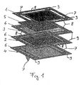
- a cathode-electrolyte-anode unit 1 which in addition to a solid electrolyte membrane as the electrolyte layer on an upper side a cathode layer and at an underside an anode layer, a punched from a flat sheet or cut by laser or electron beam cutting first layer 2 an interconnector plate and a further layer 3 of the interconnector plate arranged between the cathode-electrolyte-anode unit 1 and the first layer 2 and an additional further layer 4 of the interconnector plate, which are arranged on a side of the first layer 2 facing away from the cathode-electrolyte-anode unit 1 is.
- the further layers 3 and 4 of the interconnector plate are recessed in an active region, ie in a region which coincides with an active region of the corresponding electrochemical cell, and consist, like the first layer 2, of unshaped planar steel sheet. Instead, you can the other layers 3 and 4 also be made of planar ceramic layers.
- a cavity formed by the recess of the further layer 3 in the active region between the cathode-electrolyte-anode unit 1 and the first layer 2 accommodates a conductive porous contact element 5, which makes electrical contact between the anode layer of the cathode-electrolyte-anode layer.
- a corresponding contact element may also be provided on a side of the first layer 2 facing away from the cathode-electrolyte-anode unit 1 and, as the contact element 5 may be connected by spot welding to the first layer 2 under certain circumstances.
- the cathode-electrolyte-anode unit 1 and the layers 2, 3 and 4 of the interconnector plate are soldered together.
- a soldering paste 6 is applied in each case on an upper side of the first layer 2 and the further layers 3 and 4 of the interconnector plate, in which case it can be metal solder and / or glass solder.
- the solder paste 6 is first applied in the edge region of the layers 2, 3 and 4 of the interconnector plate, after which said layers 2, 3 and 4 with the contact element 5 and the cathode-electrolyte-anode unit 1 superimposed and pre-assembled, after which an ensemble of this kind is heated completely in an oven to a temperature of between 600 ° C and 1100 ° C and soldered together by annealing.
- This can also be Contact element 5 and any existing and in the Fig. 1 not shown further contact element with the cathode-electrolyte-anode unit or the first layer 2 of the interconnector plate are soldered.
- the porous contact element 5 consists of a nickel foam.
- the contact element 5 may also be made of another porous metal substrate, a cermet substrate or a wire mesh.
- film casting and subsequent sintering are suitable for producing the contact element 5 and corresponding further contact elements.
- the cathode-electrolyte-anode unit 1, the first layer 2 and the further layer 4 first elongated recesses 7 for supplying a fuel gas, preferably hydrogen, in a defined by the further layer 3 level and for discharging a reaction product , typically of water, from this plane defining an anode side of the cathode-electrolyte-anode unit 1.
- a fuel gas preferably hydrogen
- a reaction product typically of water
- the cathode-electrolyte-anode unit 1 for supplying an oxidant, which may be given by air or oxygen, and for discharging excess oxidant gas, the cathode-electrolyte-anode unit 1, the further layer 3 and the first layer 2 have second elongated recesses 8 in remaining regions of the edge region on, by which a supply of the oxidant is possible in a plane defined by the further layer 4, the one cathode side of a - after forming a stack of several such Wiederholticianen - adjacent further repeat unit defined.
- a round recess 9 is provided in four corners of both the cathode-electrolyte-anode unit 1 and the layers 2, 3 and 4 of the interconnector plate, which allow a stack of four anchors formed from a plurality of such repeat units to be braced.
- Such a stack typically comprises a plurality of repeating units of the type illustrated, which in some circumstances may additionally be glued or soldered together.
- the recesses 7, 8 and 9 in the cathode-electrolyte-anode unit 1 and the layers 2, 3 and 4 of the interconnector plate have been previously cut or punched out, in the case of the layers 2, 3 and 4 of flat sheet metal blanks of a thickness of about 0.5 mm.
- the cathode-electrolyte-anode unit 1 is supported by electrolytes in the present embodiment. However, cathodic or anode-supported cathode-electrolyte-anode units or else those which have their own carrier layer with a porous metal substrate would also be conceivable.
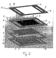
- the cathode-electrolyte-anode unit 1 is in the in the Fig. 2 shown embodiment thus between two interconnector plates, namely between the other layer 3 and the next interconnector plate associated layer 4 ', clamped on both sides, whereby a caused by different expansion coefficients of the sheets and the cathode-electrolyte-anode unit bending of the repeat unit in the production yet better avoidable.
- the embodiment of the Fig. 2 So shows a schematic structure of a repeating unit for portable high-temperature fuel cells.
- the repeat unit again has an electrolyte-supported cathode-electrolyte-anode unit 1 with air or oxygen electrode on the top.
- the electrolyte layer of this cathode-electrolyte-anode unit 1 is preconstructed to contain the openings or recesses 7 and 8 for the fuel gas and air supply to the electrodes.
- the interconnector (the interconnector plate) form in the finished stack the corresponding cut metal sheets with a thickness of 0.5 mm.
- the solder paste 6 is, as in the embodiment of the Fig.
- the contact element 5, shown again is only an anode contact element is again made of nickel foam or a nickel fleece and mechanically and electrically connected by spot welding to the first layer 2 of the interconnector.
Landscapes
- Chemical & Material Sciences (AREA)
- Engineering & Computer Science (AREA)
- Chemical Kinetics & Catalysis (AREA)
- Electrochemistry (AREA)
- General Chemical & Material Sciences (AREA)
- Life Sciences & Earth Sciences (AREA)
- Manufacturing & Machinery (AREA)
- Sustainable Development (AREA)
- Sustainable Energy (AREA)
- Materials Engineering (AREA)
- Metallurgy (AREA)
- Organic Chemistry (AREA)
- Composite Materials (AREA)
- Fuel Cell (AREA)
- Connection Of Batteries Or Terminals (AREA)
- Hybrid Cells (AREA)
- Primary Cells (AREA)
- Secondary Cells (AREA)
- Battery Mounting, Suspending (AREA)
- Battery Electrode And Active Subsutance (AREA)
Applications Claiming Priority (2)
| Application Number | Priority Date | Filing Date | Title |
|---|---|---|---|
| DE102006040030A DE102006040030B4 (de) | 2006-08-23 | 2006-08-23 | Stapeleinheit für einen Stapel elektrochemischer Zellen, Stapelanordnung und Verfahren zum Herstellen einer Stapeleinheit |
| PCT/DE2007/001540 WO2008022638A2 (de) | 2006-08-23 | 2007-08-23 | Wiederholeinheit für einen stapel elektrochemischer zellen, stapelanordnung und verfahren zum herstellen einer wiederholeinheit |
Publications (2)
| Publication Number | Publication Date |
|---|---|
| EP2054964A2 EP2054964A2 (de) | 2009-05-06 |
| EP2054964B1 true EP2054964B1 (de) | 2010-12-29 |
Family
ID=38988088
Family Applications (1)
| Application Number | Title | Priority Date | Filing Date |
|---|---|---|---|
| EP07817462A Active EP2054964B1 (de) | 2006-08-23 | 2007-08-23 | Wiederholeinheit für einen stapel elektrochemischer zellen, sowie stapelanordnung |
Country Status (7)
| Country | Link |
|---|---|
| US (1) | US20090325023A1 (da) |
| EP (1) | EP2054964B1 (da) |
| JP (1) | JP5295959B2 (da) |
| AT (1) | ATE493771T1 (da) |
| DE (2) | DE102006040030B4 (da) |
| DK (1) | DK2054964T3 (da) |
| WO (1) | WO2008022638A2 (da) |
Families Citing this family (7)
| Publication number | Priority date | Publication date | Assignee | Title |
|---|---|---|---|---|
| DE102009008989B4 (de) * | 2009-02-14 | 2017-09-07 | Elringklinger Ag | Verfahren zum elektrisch leitfähigen Verbinden eines Kontaktfeldes eines Interkonnektors mit einer elektrochemischen Zelle und Baugruppe mit einem Interkonnektor und einer elektrochemischen Zelle einer Brennstoffzelleneinheit |
| US9064805B1 (en) * | 2013-03-13 | 2015-06-23 | Itn Energy Systems, Inc. | Hot-press method |
| KR20160008213A (ko) * | 2013-05-02 | 2016-01-21 | 할도르 토프쉐 에이/에스 | Soc 장치용 가스 유입구 |
| EP2992125B1 (en) * | 2013-05-02 | 2017-10-25 | Haldor Topsøe A/S | Gas inlet for soec unit |
| DE102015205944B4 (de) | 2015-03-30 | 2021-02-18 | Fraunhofer-Gesellschaft zur Förderung der angewandten Forschung e.V. | Anordnung elektrochemischer Zellen mit Dichtungslagen sowie deren Verwendung |
| EP4575039A1 (de) * | 2023-12-22 | 2025-06-25 | sunfire GmbH | Verfahren zur herstellung einer elektrolyseanordnung |
| FR3163780B1 (fr) * | 2024-06-20 | 2026-06-12 | Genvia | Procede d’assemblage d’un interconnecteur pour module soec sofc et interconnecteur obtenu par ledit procede |
Family Cites Families (15)
| Publication number | Priority date | Publication date | Assignee | Title |
|---|---|---|---|---|
| DE4016157A1 (de) * | 1989-06-08 | 1990-12-13 | Asea Brown Boveri | Vorrichtung zur umwandlung von chemischer energie in elektrische energie mittels in serie geschalteter flacher, ebener hochtemperatur-brennstoffzellen |
| IT1270878B (it) * | 1993-04-30 | 1997-05-13 | Permelec Spa Nora | Migliorata cella elettrochimica utilizzante membrane a scambio ionico e piatti bipolari metallici |
| JPH10509840A (ja) * | 1994-12-01 | 1998-09-22 | シーメンス アクチエンゲゼルシヤフト | セラミックで被膜されたバイポーラ板を備えた燃料電池セル及びその製造方法 |
| US6146780A (en) * | 1997-01-24 | 2000-11-14 | Lynntech, Inc. | Bipolar separator plates for electrochemical cell stacks |
| US6232010B1 (en) * | 1999-05-08 | 2001-05-15 | Lynn Tech Power Systems, Ltd. | Unitized barrier and flow control device for electrochemical reactors |
| DE19841919C2 (de) * | 1998-09-12 | 2003-08-14 | Forschungszentrum Juelich Gmbh | Verfahren zur Herstellung eines Brennstoffzellenmoduls |
| DE10044703B4 (de) * | 2000-09-09 | 2013-10-17 | Elringklinger Ag | Brennstoffzelleneinheit, Brennstoffzellenblockverbund und Verfahren zum Herstellen eines Brennstoffzellenblockverbunds |
| US7270906B2 (en) * | 2002-06-24 | 2007-09-18 | Delphi Technologies, Inc. | Solid-oxide fuel cell module for a fuel cell stack |
| CA2435988A1 (en) * | 2002-07-25 | 2004-01-25 | Global Thermoelectric Inc. | Metal foam interconnect |
| JP4511779B2 (ja) * | 2002-08-05 | 2010-07-28 | パナソニック株式会社 | 燃料電池 |
| JP2004247174A (ja) * | 2003-02-13 | 2004-09-02 | Ngk Spark Plug Co Ltd | 固体電解質型燃料電池 |
| DE10317361A1 (de) * | 2003-04-15 | 2004-11-04 | Bayerische Motoren Werke Ag | Brennstoffzelle und/oder Elektrolyseur sowie Verfahren zu deren/dessen Herstellung |
| DE10358458B4 (de) * | 2003-12-13 | 2010-03-18 | Elringklinger Ag | Brennstoffzellenstapel und Verfahren zum Herstellen eines Brennstoffzellenstapels |
| US7595085B2 (en) * | 2004-03-09 | 2009-09-29 | Delphi Technologies, Inc. | Ceramic assembly with a stabilizer layer |
| US7318973B2 (en) * | 2004-08-12 | 2008-01-15 | General Motors Corporation | Stamped bridges and plates for reactant delivery for a fuel cell |
-
2006
- 2006-08-23 DE DE102006040030A patent/DE102006040030B4/de not_active Expired - Fee Related
-
2007
- 2007-08-23 EP EP07817462A patent/EP2054964B1/de active Active
- 2007-08-23 WO PCT/DE2007/001540 patent/WO2008022638A2/de not_active Ceased
- 2007-08-23 JP JP2009524898A patent/JP5295959B2/ja not_active Expired - Fee Related
- 2007-08-23 US US12/376,406 patent/US20090325023A1/en not_active Abandoned
- 2007-08-23 AT AT07817462T patent/ATE493771T1/de active
- 2007-08-23 DE DE502007006126T patent/DE502007006126D1/de active Active
- 2007-08-23 DK DK07817462.0T patent/DK2054964T3/da active
Also Published As
| Publication number | Publication date |
|---|---|
| JP2010501971A (ja) | 2010-01-21 |
| JP5295959B2 (ja) | 2013-09-18 |
| EP2054964A2 (de) | 2009-05-06 |
| DE102006040030A1 (de) | 2008-03-20 |
| DK2054964T3 (da) | 2011-04-18 |
| WO2008022638A2 (de) | 2008-02-28 |
| DE102006040030B4 (de) | 2009-09-03 |
| US20090325023A1 (en) | 2009-12-31 |
| ATE493771T1 (de) | 2011-01-15 |
| WO2008022638A3 (de) | 2008-04-10 |
| DE502007006126D1 (de) | 2011-02-10 |
Similar Documents
| Publication | Publication Date | Title |
|---|---|---|
| EP2154742B1 (de) | Brennstoffzelleneinheit und Verfahren zum Herstellen einer elektrisch leitfähigen Verbindung zwischen einer Elektrode und einer Bipolarplatte | |
| EP0966771B1 (de) | Werkstoff für elektrische kontaktschichten zwischen einer elektrode einer hochtemperatur-brennstoffzelle und einem interkonnektor | |
| DE69233190T2 (de) | Zelleinheiten für Festoxidbrennstoffzellen und Energiegeneratoren die diese Zelleinheiten verwenden | |
| EP1314217B1 (de) | Hochtemperaturbrennstoffzelle | |
| EP1662596B1 (de) | Dichtungsanordnung für einen Hochtemperatur Brennstoffzellenstapel und Verfahren zum Herstellen dieses Brennstoffzellenstapels | |
| EP0840388A1 (de) | Batterie mit planaren Hochtemperatur-Brennstoffzellen | |
| DE19841919C2 (de) | Verfahren zur Herstellung eines Brennstoffzellenmoduls | |
| EP2054964A2 (de) | Wiederholeinheit für einen stapel elektrochemischer zellen, stapelanordnung und verfahren zum herstellen einer wiederholeinheit | |
| DE102022121234A1 (de) | Elektrochemischer Reaktionszellenstapel | |
| DE19650704C2 (de) | Verbindungselement für Brennstoffzellen | |
| EP2149171B1 (de) | Trägervorrichtung für eine elektrochemische funktionseinrichtung, brennstoffzellemodul und verfahren zur herstellung einer trägervorrichtung | |
| DE102009037148B4 (de) | Festoxid-Brennstoffzellen-System | |
| WO2011141340A1 (de) | Verfahren zur herstellung einer metallischen biopolarplatte, bipolarplatte sowie brennstoffzellenstapel und verfahren zu dessen herstellung | |
| EP1665431B1 (de) | Interkonnektor für hochtemperatur-brennstoffzelleneinheit | |
| DE102022113662A1 (de) | Elektrochemische Reaktionseinzelzelle und elektrochemischer Reaktionszellenstapel | |
| DE102005034616B4 (de) | Brennstoffzelleneinheit und Brennstoffzellenstapel | |
| DE102006060137A1 (de) | Brennstoffzelle mit einem hartverlöteten Interkonnektor und Verfahren zum Zusammensetzen derselben | |
| WO2016156145A1 (de) | Anordnung elektrochemischer zellen sowie deren verwendung | |
| DE202005020601U1 (de) | Brennstoffzelleneinheit | |
| EP1301957B1 (de) | Aluminiumhaltiger interkonnektor für brennstoffzellen | |
| DE102024209735A1 (de) | Verfahren zur Herstellung eines elektrochemischen Zellenelements, elektrochemisches Zellenelements, elektrochemische Zellenvorrichtung | |
| DE102021131474A1 (de) | Elektrochemische Reaktionseinzelzelle und elektrochemischer Reaktionszellenstapel | |
| WO2014000984A1 (de) | Elektrischer energiespeicher | |
| EP2372825A1 (de) | Brennstoffzellenmodul |
Legal Events
| Date | Code | Title | Description |
|---|---|---|---|
| PUAI | Public reference made under article 153(3) epc to a published international application that has entered the european phase |
Free format text: ORIGINAL CODE: 0009012 |
|
| 17P | Request for examination filed |
Effective date: 20090204 |
|
| AK | Designated contracting states |
Kind code of ref document: A2 Designated state(s): AT BE BG CH CY CZ DE DK EE ES FI FR GB GR HU IE IS IT LI LT LU LV MC MT NL PL PT RO SE SI SK TR |
|
| AX | Request for extension of the european patent |
Extension state: AL BA HR MK RS |
|
| 17Q | First examination report despatched |
Effective date: 20090603 |
|
| DAX | Request for extension of the european patent (deleted) | ||
| RTI1 | Title (correction) |
Free format text: REPETITION UNIT FOR A STACK OF ELECTROCHEMICAL CELLS AND STACK ARRANGEMENT |
|
| GRAP | Despatch of communication of intention to grant a patent |
Free format text: ORIGINAL CODE: EPIDOSNIGR1 |
|
| GRAS | Grant fee paid |
Free format text: ORIGINAL CODE: EPIDOSNIGR3 |
|
| GRAA | (expected) grant |
Free format text: ORIGINAL CODE: 0009210 |
|
| AK | Designated contracting states |
Kind code of ref document: B1 Designated state(s): AT BE BG CH CY CZ DE DK EE ES FI FR GB GR HU IE IS IT LI LT LU LV MC MT NL PL PT RO SE SI SK TR |
|
| REG | Reference to a national code |
Ref country code: GB Ref legal event code: FG4D Free format text: NOT ENGLISH |
|
| REG | Reference to a national code |
Ref country code: CH Ref legal event code: EP |
|
| REG | Reference to a national code |
Ref country code: IE Ref legal event code: FG4D Free format text: LANGUAGE OF EP DOCUMENT: GERMAN |
|
| REF | Corresponds to: |
Ref document number: 502007006126 Country of ref document: DE Date of ref document: 20110210 Kind code of ref document: P |
|
| REG | Reference to a national code |
Ref country code: DE Ref legal event code: R096 Ref document number: 502007006126 Country of ref document: DE Effective date: 20110210 |
|
| REG | Reference to a national code |
Ref country code: CH Ref legal event code: NV Representative=s name: ROSENICH PAUL; GISLER CHRISTIAN PATENTBUERO PAUL R |
|
| REG | Reference to a national code |
Ref country code: DK Ref legal event code: T3 |
|
| REG | Reference to a national code |
Ref country code: NL Ref legal event code: VDEP Effective date: 20101229 |
|
| PG25 | Lapsed in a contracting state [announced via postgrant information from national office to epo] |
Ref country code: LT Free format text: LAPSE BECAUSE OF FAILURE TO SUBMIT A TRANSLATION OF THE DESCRIPTION OR TO PAY THE FEE WITHIN THE PRESCRIBED TIME-LIMIT Effective date: 20101229 |
|
| LTIE | Lt: invalidation of european patent or patent extension |
Effective date: 20101229 |
|
| PG25 | Lapsed in a contracting state [announced via postgrant information from national office to epo] |
Ref country code: CY Free format text: LAPSE BECAUSE OF FAILURE TO SUBMIT A TRANSLATION OF THE DESCRIPTION OR TO PAY THE FEE WITHIN THE PRESCRIBED TIME-LIMIT Effective date: 20101229 Ref country code: BG Free format text: LAPSE BECAUSE OF FAILURE TO SUBMIT A TRANSLATION OF THE DESCRIPTION OR TO PAY THE FEE WITHIN THE PRESCRIBED TIME-LIMIT Effective date: 20110329 Ref country code: SI Free format text: LAPSE BECAUSE OF FAILURE TO SUBMIT A TRANSLATION OF THE DESCRIPTION OR TO PAY THE FEE WITHIN THE PRESCRIBED TIME-LIMIT Effective date: 20101229 Ref country code: SE Free format text: LAPSE BECAUSE OF FAILURE TO SUBMIT A TRANSLATION OF THE DESCRIPTION OR TO PAY THE FEE WITHIN THE PRESCRIBED TIME-LIMIT Effective date: 20101229 Ref country code: LV Free format text: LAPSE BECAUSE OF FAILURE TO SUBMIT A TRANSLATION OF THE DESCRIPTION OR TO PAY THE FEE WITHIN THE PRESCRIBED TIME-LIMIT Effective date: 20101229 Ref country code: FI Free format text: LAPSE BECAUSE OF FAILURE TO SUBMIT A TRANSLATION OF THE DESCRIPTION OR TO PAY THE FEE WITHIN THE PRESCRIBED TIME-LIMIT Effective date: 20101229 |
|
| REG | Reference to a national code |
Ref country code: IE Ref legal event code: FD4D |
|
| PG25 | Lapsed in a contracting state [announced via postgrant information from national office to epo] |
Ref country code: EE Free format text: LAPSE BECAUSE OF FAILURE TO SUBMIT A TRANSLATION OF THE DESCRIPTION OR TO PAY THE FEE WITHIN THE PRESCRIBED TIME-LIMIT Effective date: 20101229 Ref country code: ES Free format text: LAPSE BECAUSE OF FAILURE TO SUBMIT A TRANSLATION OF THE DESCRIPTION OR TO PAY THE FEE WITHIN THE PRESCRIBED TIME-LIMIT Effective date: 20110409 Ref country code: IS Free format text: LAPSE BECAUSE OF FAILURE TO SUBMIT A TRANSLATION OF THE DESCRIPTION OR TO PAY THE FEE WITHIN THE PRESCRIBED TIME-LIMIT Effective date: 20110429 Ref country code: GR Free format text: LAPSE BECAUSE OF FAILURE TO SUBMIT A TRANSLATION OF THE DESCRIPTION OR TO PAY THE FEE WITHIN THE PRESCRIBED TIME-LIMIT Effective date: 20110330 Ref country code: PT Free format text: LAPSE BECAUSE OF FAILURE TO SUBMIT A TRANSLATION OF THE DESCRIPTION OR TO PAY THE FEE WITHIN THE PRESCRIBED TIME-LIMIT Effective date: 20110429 Ref country code: CZ Free format text: LAPSE BECAUSE OF FAILURE TO SUBMIT A TRANSLATION OF THE DESCRIPTION OR TO PAY THE FEE WITHIN THE PRESCRIBED TIME-LIMIT Effective date: 20101229 |
|
| PG25 | Lapsed in a contracting state [announced via postgrant information from national office to epo] |
Ref country code: PL Free format text: LAPSE BECAUSE OF FAILURE TO SUBMIT A TRANSLATION OF THE DESCRIPTION OR TO PAY THE FEE WITHIN THE PRESCRIBED TIME-LIMIT Effective date: 20101229 Ref country code: SK Free format text: LAPSE BECAUSE OF FAILURE TO SUBMIT A TRANSLATION OF THE DESCRIPTION OR TO PAY THE FEE WITHIN THE PRESCRIBED TIME-LIMIT Effective date: 20101229 Ref country code: RO Free format text: LAPSE BECAUSE OF FAILURE TO SUBMIT A TRANSLATION OF THE DESCRIPTION OR TO PAY THE FEE WITHIN THE PRESCRIBED TIME-LIMIT Effective date: 20101229 Ref country code: NL Free format text: LAPSE BECAUSE OF FAILURE TO SUBMIT A TRANSLATION OF THE DESCRIPTION OR TO PAY THE FEE WITHIN THE PRESCRIBED TIME-LIMIT Effective date: 20101229 |
|
| PG25 | Lapsed in a contracting state [announced via postgrant information from national office to epo] |
Ref country code: IE Free format text: LAPSE BECAUSE OF FAILURE TO SUBMIT A TRANSLATION OF THE DESCRIPTION OR TO PAY THE FEE WITHIN THE PRESCRIBED TIME-LIMIT Effective date: 20101229 |
|
| PLBE | No opposition filed within time limit |
Free format text: ORIGINAL CODE: 0009261 |
|
| STAA | Information on the status of an ep patent application or granted ep patent |
Free format text: STATUS: NO OPPOSITION FILED WITHIN TIME LIMIT |
|
| 26N | No opposition filed |
Effective date: 20110930 |
|
| PG25 | Lapsed in a contracting state [announced via postgrant information from national office to epo] |
Ref country code: MT Free format text: LAPSE BECAUSE OF FAILURE TO SUBMIT A TRANSLATION OF THE DESCRIPTION OR TO PAY THE FEE WITHIN THE PRESCRIBED TIME-LIMIT Effective date: 20101229 |
|
| REG | Reference to a national code |
Ref country code: DE Ref legal event code: R097 Ref document number: 502007006126 Country of ref document: DE Effective date: 20110930 |
|
| BERE | Be: lapsed |
Owner name: FRAUNHOFER-GESELLSCHAFT ZUR FORDERUNG DER ANGEWAN Effective date: 20110831 |
|
| PG25 | Lapsed in a contracting state [announced via postgrant information from national office to epo] |
Ref country code: MC Free format text: LAPSE BECAUSE OF NON-PAYMENT OF DUE FEES Effective date: 20110831 |
|
| PG25 | Lapsed in a contracting state [announced via postgrant information from national office to epo] |
Ref country code: BE Free format text: LAPSE BECAUSE OF NON-PAYMENT OF DUE FEES Effective date: 20110831 |
|
| PG25 | Lapsed in a contracting state [announced via postgrant information from national office to epo] |
Ref country code: LU Free format text: LAPSE BECAUSE OF NON-PAYMENT OF DUE FEES Effective date: 20110823 |
|
| PG25 | Lapsed in a contracting state [announced via postgrant information from national office to epo] |
Ref country code: TR Free format text: LAPSE BECAUSE OF FAILURE TO SUBMIT A TRANSLATION OF THE DESCRIPTION OR TO PAY THE FEE WITHIN THE PRESCRIBED TIME-LIMIT Effective date: 20101229 |
|
| PG25 | Lapsed in a contracting state [announced via postgrant information from national office to epo] |
Ref country code: HU Free format text: LAPSE BECAUSE OF FAILURE TO SUBMIT A TRANSLATION OF THE DESCRIPTION OR TO PAY THE FEE WITHIN THE PRESCRIBED TIME-LIMIT Effective date: 20101229 |
|
| REG | Reference to a national code |
Ref country code: FR Ref legal event code: PLFP Year of fee payment: 10 |
|
| REG | Reference to a national code |
Ref country code: FR Ref legal event code: PLFP Year of fee payment: 11 |
|
| REG | Reference to a national code |
Ref country code: FR Ref legal event code: PLFP Year of fee payment: 12 |
|
| PGFP | Annual fee paid to national office [announced via postgrant information from national office to epo] |
Ref country code: DK Payment date: 20190822 Year of fee payment: 13 |
|
| REG | Reference to a national code |
Ref country code: CH Ref legal event code: PCAR Free format text: NEW ADDRESS: ROTENBODENSTRASSE 12, 9497 TRIESENBERG (LI) |
|
| REG | Reference to a national code |
Ref country code: DK Ref legal event code: EBP Effective date: 20200831 |
|
| PG25 | Lapsed in a contracting state [announced via postgrant information from national office to epo] |
Ref country code: DK Free format text: LAPSE BECAUSE OF NON-PAYMENT OF DUE FEES Effective date: 20200831 |
|
| PGFP | Annual fee paid to national office [announced via postgrant information from national office to epo] |
Ref country code: IT Payment date: 20230831 Year of fee payment: 17 Ref country code: GB Payment date: 20230824 Year of fee payment: 17 Ref country code: CH Payment date: 20230902 Year of fee payment: 17 Ref country code: AT Payment date: 20230818 Year of fee payment: 17 |
|
| PGFP | Annual fee paid to national office [announced via postgrant information from national office to epo] |
Ref country code: FR Payment date: 20230821 Year of fee payment: 17 |
|
| REG | Reference to a national code |
Ref country code: CH Ref legal event code: PL |
|
| REG | Reference to a national code |
Ref country code: AT Ref legal event code: MM01 Ref document number: 493771 Country of ref document: AT Kind code of ref document: T Effective date: 20240823 |
|
| GBPC | Gb: european patent ceased through non-payment of renewal fee |
Effective date: 20240823 |
|
| PG25 | Lapsed in a contracting state [announced via postgrant information from national office to epo] |
Ref country code: AT Free format text: LAPSE BECAUSE OF NON-PAYMENT OF DUE FEES Effective date: 20240823 Ref country code: CH Free format text: LAPSE BECAUSE OF NON-PAYMENT OF DUE FEES Effective date: 20240831 |
|
| PG25 | Lapsed in a contracting state [announced via postgrant information from national office to epo] |
Ref country code: GB Free format text: LAPSE BECAUSE OF NON-PAYMENT OF DUE FEES Effective date: 20240823 |
|
| PG25 | Lapsed in a contracting state [announced via postgrant information from national office to epo] |
Ref country code: IT Free format text: LAPSE BECAUSE OF NON-PAYMENT OF DUE FEES Effective date: 20240823 |
|
| PG25 | Lapsed in a contracting state [announced via postgrant information from national office to epo] |
Ref country code: FR Free format text: LAPSE BECAUSE OF NON-PAYMENT OF DUE FEES Effective date: 20240831 |
|
| PGFP | Annual fee paid to national office [announced via postgrant information from national office to epo] |
Ref country code: DE Payment date: 20250819 Year of fee payment: 19 |