EP2053702A2 - A connector device and locking structure - Google Patents
A connector device and locking structure Download PDFInfo
- Publication number
- EP2053702A2 EP2053702A2 EP08018475A EP08018475A EP2053702A2 EP 2053702 A2 EP2053702 A2 EP 2053702A2 EP 08018475 A EP08018475 A EP 08018475A EP 08018475 A EP08018475 A EP 08018475A EP 2053702 A2 EP2053702 A2 EP 2053702A2
- Authority
- EP
- European Patent Office
- Prior art keywords
- spring
- portions
- leg portions
- passages
- unlocking
- Prior art date
- Legal status (The legal status is an assumption and is not a legal conclusion. Google has not performed a legal analysis and makes no representation as to the accuracy of the status listed.)
- Granted
Links
- 230000013011 mating Effects 0.000 claims description 21
- 230000000694 effects Effects 0.000 claims description 8
- 238000006073 displacement reaction Methods 0.000 description 29
- 238000010276 construction Methods 0.000 description 12
- 238000003780 insertion Methods 0.000 description 8
- 230000037431 insertion Effects 0.000 description 8
- 238000012986 modification Methods 0.000 description 8
- 230000004048 modification Effects 0.000 description 8
- 238000000926 separation method Methods 0.000 description 7
- 229920003002 synthetic resin Polymers 0.000 description 7
- 239000000057 synthetic resin Substances 0.000 description 7
- 230000000452 restraining effect Effects 0.000 description 5
- 239000000470 constituent Substances 0.000 description 4
- 230000000149 penetrating effect Effects 0.000 description 4
- 238000007789 sealing Methods 0.000 description 4
- 230000003247 decreasing effect Effects 0.000 description 3
- 230000002159 abnormal effect Effects 0.000 description 1
- 238000005299 abrasion Methods 0.000 description 1
- 230000009194 climbing Effects 0.000 description 1
- 230000001419 dependent effect Effects 0.000 description 1
- 230000003993 interaction Effects 0.000 description 1
Images















Classifications
-
- H—ELECTRICITY
- H01—ELECTRIC ELEMENTS
- H01R—ELECTRICALLY-CONDUCTIVE CONNECTIONS; STRUCTURAL ASSOCIATIONS OF A PLURALITY OF MUTUALLY-INSULATED ELECTRICAL CONNECTING ELEMENTS; COUPLING DEVICES; CURRENT COLLECTORS
- H01R13/00—Details of coupling devices of the kinds covered by groups H01R12/70 or H01R24/00 - H01R33/00
- H01R13/62—Means for facilitating engagement or disengagement of coupling parts or for holding them in engagement
- H01R13/639—Additional means for holding or locking coupling parts together, after engagement, e.g. separate keylock, retainer strap
-
- H—ELECTRICITY
- H01—ELECTRIC ELEMENTS
- H01R—ELECTRICALLY-CONDUCTIVE CONNECTIONS; STRUCTURAL ASSOCIATIONS OF A PLURALITY OF MUTUALLY-INSULATED ELECTRICAL CONNECTING ELEMENTS; COUPLING DEVICES; CURRENT COLLECTORS
- H01R13/00—Details of coupling devices of the kinds covered by groups H01R12/70 or H01R24/00 - H01R33/00
- H01R13/62—Means for facilitating engagement or disengagement of coupling parts or for holding them in engagement
- H01R13/627—Snap or like fastening
- H01R13/6277—Snap or like fastening comprising annular latching means, e.g. ring snapping in an annular groove
-
- H—ELECTRICITY
- H01—ELECTRIC ELEMENTS
- H01R—ELECTRICALLY-CONDUCTIVE CONNECTIONS; STRUCTURAL ASSOCIATIONS OF A PLURALITY OF MUTUALLY-INSULATED ELECTRICAL CONNECTING ELEMENTS; COUPLING DEVICES; CURRENT COLLECTORS
- H01R13/00—Details of coupling devices of the kinds covered by groups H01R12/70 or H01R24/00 - H01R33/00
- H01R13/62—Means for facilitating engagement or disengagement of coupling parts or for holding them in engagement
-
- H—ELECTRICITY
- H01—ELECTRIC ELEMENTS
- H01R—ELECTRICALLY-CONDUCTIVE CONNECTIONS; STRUCTURAL ASSOCIATIONS OF A PLURALITY OF MUTUALLY-INSULATED ELECTRICAL CONNECTING ELEMENTS; COUPLING DEVICES; CURRENT COLLECTORS
- H01R13/00—Details of coupling devices of the kinds covered by groups H01R12/70 or H01R24/00 - H01R33/00
- H01R13/62—Means for facilitating engagement or disengagement of coupling parts or for holding them in engagement
- H01R13/627—Snap or like fastening
- H01R13/6271—Latching means integral with the housing
- H01R13/6272—Latching means integral with the housing comprising a single latching arm
-
- H—ELECTRICITY
- H01—ELECTRIC ELEMENTS
- H01R—ELECTRICALLY-CONDUCTIVE CONNECTIONS; STRUCTURAL ASSOCIATIONS OF A PLURALITY OF MUTUALLY-INSULATED ELECTRICAL CONNECTING ELEMENTS; COUPLING DEVICES; CURRENT COLLECTORS
- H01R13/00—Details of coupling devices of the kinds covered by groups H01R12/70 or H01R24/00 - H01R33/00
- H01R13/62—Means for facilitating engagement or disengagement of coupling parts or for holding them in engagement
- H01R13/629—Additional means for facilitating engagement or disengagement of coupling parts, e.g. aligning or guiding means, levers, gas pressure electrical locking indicators, manufacturing tolerances
- H01R13/633—Additional means for facilitating engagement or disengagement of coupling parts, e.g. aligning or guiding means, levers, gas pressure electrical locking indicators, manufacturing tolerances for disengagement only
- H01R13/6335—Additional means for facilitating engagement or disengagement of coupling parts, e.g. aligning or guiding means, levers, gas pressure electrical locking indicators, manufacturing tolerances for disengagement only comprising a handle
Definitions
- the present invention relates to a pair of connectors connectable with each other and to a locking construction.
- a specified clearance is defined between the engaging portion and the locking projection lest the engaging portion and the locking projection should interfere with each other when the lock arm is resiliently restored.
- the connector when the connector is subjected to vibration or the like, there may be backlash between the locking projection and the engaging portion, with the result that abnormal noise may be produced or terminals may slide against each other to be abraded.
- the clearance between the locking projection and the engaging portion may be enlarged due to creep deformation. Therefore, a countermeasure against the backlash is asked for.
- a locking structure for example, disclosed in Japanese Utility Model Publication No. H01-98485 is known as the one for locking a pair of members in a properly connected state by a spring.
- the spring includes a pair of resiliently displaceable leg portions and is vertically displaceably mounted on a housing of a connector, and the housing is formed with passages, in which locking projections provided on a mating housing pass.
- the leg portions of the spring project into the passages and are located backward (separating direction from the mating housing) of the locking projections, and the two connectors are locked in a properly connected state by the engagement of the leg portions and the locking projections.
- the locked state is canceled by pressing the spring down to retract the leg portions from the passages.
- the spring has to be directly pressed down (i.e. unlocking operation) by fingertips. Since the spring is thinner than the fingertips, there is a problem of poor operability.
- the unlocking operation has to be performed using a jig or the like, which presents a problem of requiring labor and time for the unlocking operation.
- the spring may be displaced to inadvertently cancel the locked state, for example, if the connector device is used in a high-vibration environment.
- the spring in order to cancel the locked state, the spring has to be in a displaceable state to a certain extent. Thus, a countermeasure has been asked for.
- the present invention was developed in view of the above situation, and an object thereof is to provide a connector device having an improved overall operability.
- a connector device or assembly comprising a pair of first and second connectors to be properly connected particularly by at least partly fitting the first connector into the second connector, wherein:
- the slanted surface and the first connector are set to come into contact at a position where a clearance is defined before the first connector in a connecting direction with the second connector.
- the first connector comes or can come substantially into contact with the slanted surface of the second connector with the clearance defined before the first connector and the resiliently at least partly restored leg portions press the engageable surfaces, whereby the housing formed with the engageable surfaces is pushed or displaced forward in the connecting direction.
- the housing moves forward because of the resilient restoring forces of the leg portions and the first connector is held in contact with the second connector. Therefore, the backlash of the two connectors can be prevented thus improving overall operability.
- a part of the first connector to be brought into contact with the slanted surface of the second connector may be formed with at least one inclined surface inclined substantially in conformity with the slanted surface(s).
- the spring may be displaceable between an inserted position where the leg portions at least partly project into the passages and a retracted position where the leg portions are substantially retracted from the passages, and/or the communicating portions and/or the leg portions may include one or more guiding portions inclined with respect to a displacing direction of the spring.
- the spring can be smoothly displaced.
- the mounting portion may be provided on the outer circumferential surface of the second connector, and at least one pair of circumferentially extending wall portions may be provided before and after the mounting portion on the outer circumferential surface of the second connector.
- the spring is mounted between the wall portions, wherefore backlash between the second connector and the spring can be reduced.
- a connector device capable of preventing backlash.
- a locking structure for inseparably locking an other member properly connected with one member by at least one spring including at least one pair of resiliently displaceable leg portions and mounted on the one member, wherein:
- the spring is displaced from the inserted position to the retracted position to effect the locked state when the unlocking portion is pressed. Since the spring needs not be directly operated with fingertips, operability is good. Further, since the unlocking portion is provided at the rear end portion of the unlocking arm in the connecting direction with the other member, the locked state can be canceled without any problem even if there is no space to place fingertips on the front end portion of the one member in the connecting direction (end portion where the spring is mounted) due to the shape of the other member or the like. Therefore, as compared with the case where an unlocking operation is performed using a jig or the like, labor and time required for this operation can be saved.
- the locking structure may comprise a supporting arm extending in the connecting direction with the other member and adapted to support the unlocking arm, a rear end portion of the supporting arm substantially in the connecting direction may be connected with the rear end portion of the unlocking arm in the connecting direction and a front end portion thereof in the connecting direction may be connected with the one member, and one of the unlocking arm and the one member may preferably include a supporting point portion for coming into contact with the other in an intermediate part, preferably substantially in a central part, of the unlocking arm in forward and backward directions when the unlocking portion is pressed to bring the unlocking arm and the one member closer to each other.
- the supporting arm is inclined to bring the unlocking arm closer to the one member and the unlocking arm is inclined like a seesaw by the contact with the supporting point portion to cancel the locked state.
- the strength of the connecting part can be accordingly reduced.
- the connecting part of the unlocking arm and the one member doubles as the supporting point portion for a seesaw-like inclining movement, the connecting part is enlarged to have sufficient strength. Then, the rigidity of the connecting part is increased and a correspondingly large force is required upon pressing the unlocking portion.
- the rigidity of the connecting part of the one member and the unlocking arm can be reduced according to the construction of the present invention, a smaller force is required for the unlocking operation. As a result, the unlocking operation can be easily performed.
- the locking structure may comprise guiding tapered portions arranged at entrances for the leg portions to the passages, located at sides, toward which the leg portions resiliently return, with respect to engaging portions of the leg portions at least partly projecting into the passages when the spring is at the retracted position, and inclined to guide the engaging portions toward the passages by resilient restoring forces of the leg portions.
- the pressing portion may be shaped to be deflected toward a side, toward which the spring is pressed, when the spring is pressed to move.
- a connector device or assembly in particular according to the first aspect of the invention or a preferred embodiment thereof, comprising a locking structure according to the invention of the above aspect or a preferred embodiment thereof, in which a mating housing as an other member properly connected with a housing as one member is inseparably locked by the spring.
- a connector device or assembly in which a mating housing properly connected with a housing is inseparably locked by a spring including a pair of resiliently displaceable leg portions and mounted on the housing, wherein:
- a locking structure for locking a pair of members in a properly connected state by a spring and a connector device to be locked in a properly connected state by a spring, the locking structure and the connector device enabling lock-related operations to be easily performed.
- a locking structure for inseparably locking an other member properly connected with one member by at least one spring including at least one pair of resiliently displaceable leg portions and mountable or mounted on or to or into the one member, wherein:
- the pressing surface interacts (preferably comes substantially into sliding contact) with the spring to press or move or displace the spring towards or to the retracted position, thereby canceling the locked state.
- the spring needs not be directly operated with fingertips, operability is good thus improving overall operability.
- the locked state can be canceled without any problem even if there is no space to place fingertips on the front end portion of the one member in the connecting direction (end portion where the spring is mounted) due to the shape of the other member or the like. Therefore, as compared with the case where an unlocking operation is performed using a jig or the like, labor and time required for this operation can be saved thus improving overall operability.
- a contact portion for coming into contact with the other member substantially in the connecting direction after the spring is displaced or pressed to the retracted position may project from the slider.
- the one member can be pulled out in a separating direction with the contact portion held in contact with the other member.
- an operation of separating the two members can be more easily performed as compared with the case where the one member is pulled out of the other member while being held by fingertips.
- the locking structure may comprise one or more guiding tapered portions arranged at or near entrances for the leg portions to the passages, located at sides, toward which the leg portions resiliently return, with respect to engaging portions of the leg portions at least partly projecting into the passages when the spring is at the retracted position, and preferably inclined to guide the engaging portions toward the passages by resilient restoring forces of the leg portions.
- the spring may reach the retracted position from the inserted position by being displaced in a direction toward the one member. Then, a displacing direction of the spring during the unlocking operation is opposite to a separating direction of the spring from the one member, wherefore an inadvertent detachment of the spring from the one member during the unlocking operation can be prevented.
- the contact portion may project substantially in the connecting direction at a side of the spring substantially opposite to the one member. Then, a displacement of the spring toward the side opposite to the one member (i.e. toward the side away from the one member) is prevented, with the result that the detachment of the spring from the one member can be prevented.
- the movable member may press a central or intermediate part of the spring between the pair of leg portions. Then, since the movable member (preferably the slider) interacts with or presses the intermediate or substantially widthwise central part (between the pair of leg portions) of the spring, the force for pressing the spring acts in a well-balanced manner and the unlocking operation can be efficiently performed.
- the one member may include at least one lift preventing portion arranged at a side of the slider substantially opposite to the one member. Since the lift of the movable member (preferably the slider) during the movement or sliding operation is prevented by this lift preventing portion, it is not necessary to press the movable member (preferably the slider) so that the movable member (preferably the slider) will not lift and the unlocking operation can be easily performed. Thus, overall operability is improved.
- a connector device or assembly in particular according to the previous aspect(s) of the invention or pa preferred embodiment thereof, comprising a locking structure according the invention or a preferred embodiment thereof, in which a mating housing as the other member properly connected with a housing as one member is inseparably locked by the at least one spring.
- a connector device or assembly in which a mating housing properly connected with a housing is inseparably locked by a spring including a pair of resiliently displaceable leg portions and mounted on the housing, characterized in that:
- a locking structure for locking a pair of members in a properly connected state by a spring and a connector device to be locked in a properly connected state by a spring, the locking structure and the connector device enabling lock-related operations to be easily performed.
- a locking structure for inseparably locking an other member properly connected with one member by at least one spring including at least one pair of resiliently displaceable leg portions and mounted on or to or onto the one member, wherein:
- the pressing portion of the unlocking arm presses or displaces the spring in the direction substantially away from the one member to cancel the locked state.
- the displacement of the spring is prevented since the spring is held at least partly between the bulging portion and the pressing portion.
- the locked state can be canceled and the displacement of the spring can be prevented.
- a locked state is enabled to be canceled and capable of preventing the displacement of a spring so that overall operability is improved.
- the bulging portion may be provided substantially in correspondence with a substantially middle part of the spring between the pair of leg portions.
- the spring has its widthwise central part (substantially middle part between the pair of leg portions) held at least partly between the bulging portion and the pressing portion.
- the pressing portion may be shaped to be deflected toward a side, toward which the spring is pressed, when the spring is pressed to move. Then, during an unlocking operation, the spring is pressed against the deflected part of the pressing portion and the separation thereof from the pressing portion can be prevented.
- the spring may be at least partly mounted in a substantially circumferentially extending groove portion formed in the one member. Then, the longitudinal displacement of the spring can be prevented.
- connector device or assembly in particular according to one or more above aspects or preferred embodiments thereof, comprising a locking structure according to the above aspect or a preferred embodiment thereof, in which a mating housing as the other member properly connected with a housing as the one member is inseparably locked by the at least one spring.
- a connector device in which a mating housing properly connected with a housing is inseparably locked by a spring including a pair of resiliently displaceable leg portions and mounted on the housing, characterized in that:
- a locking structure and a connector device enabling a locked state to be easily canceled and capable of preventing the displacement of a spring.
- FIGS. 1 to 7 one preferred embodiment of the present invention is described with reference to FIGS. 1 to 7 .
- a connector device or assembly according to this embodiment is provided at least with a male connector (corresponding to a preferred first connector) and a female connector 20 (corresponding to a preferred second connector) connectable with each other.
- a male connector corresponding to a preferred first connector
- a female connector 20 corresponding to a preferred second connector
- sides of the two connectors 10, 20 to be connected are respectively referred to as front sides and reference is made to FIG. 1 concerning upper and lower sides.
- the male connector 10 includes a male housing 11 and one or more male terminals 12 held at least partly in this male housing 11.
- the male housing 11 is made e.g. of synthetic resin and includes a front receptacle 13 and a rear receptacle 14 (preferably substantially in the form of rectangular tubes slightly longer in a width direction), the front receptacle 13 having an open front side and the rear receptacle 14 having an open rear side.
- the thickness (dimension in inward and outward directions) of the front receptacle 13 preferably is smaller in its front portion (preferably substantially front half) than in its rear portion (preferably substantially rear half).
- One or more engaging projections 16 (corresponding to preferred engageable portions) projecting outwardly or laterally (to left and/or right) are provided on the (preferably substantially opposite) outer or lateral (left and/or right) surface(s) of the male housing 11.
- the engaging projections 16 are described in detail later.
- One or more (e.g. three) male terminals 12 are provided preferably substantially side by side in the width direction at one or more stages and held while penetrating a back wall 15 (wall between the front receptacle 13 and the rear receptacle 14) of the male housing 11. Front and rear parts of the (three) male terminals 12 respectively at least partly project substantially forward and backward in the front receptacle 13 and the rear receptacle 14.
- the female connector 20 includes a female housing 21 made e.g. of synthetic resin and connectable with the male housing 11.
- the female housing 21 includes a terminal accommodating portion 23 capable of at least partly accommodating one or more female terminals 22 and an outer tube portion 24 at least partly surrounding the outer circumferential surface of the terminal accommodating portion 23.
- the terminal accommodating portion 23 preferably substantially is in the form of a rectangular column at least partly fittable into the front receptacle 13 of the male housing 11 and/or preferably having a cross section slightly longer in the width direction, and three cavities 25, into which the female terminals 22 are at least partly insertable from an insertion side, preferably substantially from behind, are formed preferably substantially side by side in the terminal accommodating portion 23.
- the outer tube portion 24 has a substantially tubular shape as a whole and extends from or at the rear end to the front end of the terminal accommodating portion 23, and the rear end of the outer tube portion 24 and the rear end of the terminal accommodating portion 23 preferably are connected by a connecting portion 26. Between the outer tube portion 24 and the terminal accommodating portion 23 is defined a clearance, into which the front receptacle 13 of the male housing 11 is at least partly insertable. A part between the outer tube portion 24 and the terminal accommodating portion 23 serves as a fitting portion 27, into which the male connector 10 is to be at least partly fitted or inserted.
- An opening 24A used to preferably assemble a retainer 48 for retaining the female terminals 22 into the terminal accommodating portion 23 is formed preferably in the lateral (lower) surface of the outer tube portion 24.
- a seal ring 28 preferably is fitted or mounted at a position preferably near the rear end. Sealing preferably is provided between the housings 11 and 12 by the seal ring 28 squeezed or deformed substantially between the front receptacle 13 and the terminal accommodating portion 23.
- One or more, preferably a pair of finger placing portions 29 projecting outwardly or laterally (to left and/or right) from the (preferably substantially opposite) outer or lateral (left and/or right) surface(s) are provided preferably at or near a rear end portion of the female housing 21. Fingertips can be placed on the (preferably both) finger placing portion(s) 29 to pull the female housing 21 out upon separating the both connectors 10, 20.
- One or more, preferably a pair of standing walls 31 extending substantially in forward and backward directions are provided on the outer or lateral (upper) surface of the outer tube portion 24 while preferably being spaced apart by a specified (predetermined or predeterminable) distance in the width direction.
- the (pair of) standing wall(s) 31 continuously extend(s) from the rear end of the female housing 21 (or close thereto) to a position near the front end thereof.
- first positioning walls 32 circumferentially extending from the front ends of the pair of standing walls 31 are provided on the (preferably substantially opposite) side surface(s) of the outer tube portion 24, and at least one second positioning wall 33 is provided on the outer tube portion 24 before or adjacent to the first positioning wall(s) 32.
- the second positioning wall 33 preferably is a circumferential wall extending over the outer (upper) surface and the opposite side surfaces of the outer tube portion 24.
- the second positioning wall 33 and the first positioning wall(s) 32 preferably are substantially parallel to each other, and/or a space having a dimension substantially equal to the width (diameter) of a spring 50 (as a preferred biasing member) in forward and backward directions is defined therebetween.
- the first positioning walls 32 and the second positioning wall 33 preferably correspond to a pair of wall portions.
- a front recess 34 having an open front side is formed in a widthwise intermediate position (preferably substantially in the widthwise center) of a part of the second positioning wall 33 extending substantially along the lateral (upper) surface of the outer tube portion 24.
- the front recess 34 preferably is so formed as to be gradually deeper from the opposite widthwise ends thereof toward the center thereof, and its depth in an intermediate part (preferably substantially in a central part) is less than 2/3, preferably about half the thickness (width in forward and backward directions) of the second positioning wall 33.
- a part of the outer tube portion 24 between the first positioning wall(s) 32 and the second positioning wall 33 serves as a mounting portion 35, on or to which the spring 50 is mounted.
- the female housing 21 corresponds to a preferred one housing
- the male housing 11 corresponds to a preferred other housing.
- the mounting portion 35 is formed by an inwardly recessed part of the outer circumferential surface of the outer tube portion 24, the first positioning walls 32 and the second positioning wall 33.
- One or more passages 36 in which the engaging projections 16 of the male housing 11 can pass, are formed in the (preferably substantially opposite) outer or lateral (left and/or right) walls of the outer tube portion 24.
- Each passage 36 preferably is a groove having an open inner side (toward the terminal accommodating portion 23), extends backward from the front end of the outer tube portion 24 and/or communicates with the mounting portion 35.
- Upper surfaces 37A and/or lower surfaces 37B of communicating portions 37 communicating the mounting portion 35 and the passages 36 preferably are inclined to approach each other from the outer side (mounting portion 35 side) toward the inner side, and/or a vertical dimension of the communicating portions 37 at the inner sides preferably is substantially equal to that of the engaging projections 16 (see FIG. 5 ).
- the spring 50 preferably has a substantially U-shape with an open bottom side as a whole and includes a pair of leg portions 51 resiliently displaceable in directions substantially facing each other and an upper side portion 52 connecting the upper ends of the leg portions 51.
- the pair of leg portions 51 extend at an angle different from 0° or 180°, preferably substantially normal (preferably substantially vertically downward) with respect to the upper side portion 52 from the opposite ends of the upper side portion 51 in a nature or undeflected state.
- Bottom or distal end parts of the pair of leg portions 51 are bent to have substantially pointed or triangular shapes pointed inwardly (in directions toward each other), and these bent parts serve as engaging portions 53 projecting at least partly into the passages 36 via the communicating portions 37.
- the engaging portions 53 include closer or upper inclined sides 53A inclined inwardly toward each other and distal or lower inclined sides 53B, and are shaped to have a smaller width or extension in a vertical direction (projecting direction) toward the inner side as a whole.
- the upper inclined sides 53A and the lower inclined sides 53B preferably have substantially the same inclinations as the upper surfaces 37A and the lower surfaces 37B of the communicating portions 37.
- the projecting ends (boundaries between the upper inclined sides 53A and the lower inclined sides 53B) of the engaging portions 53 preferably are rounded.
- the spring 50 is so mounted as to be displaceable between an inserted position IP (see FIG. 5 ) where the engaging portions 53 project into the passages 36 and a retracted position RP (see FIG. 6 ) where the engaging portions 53 are retracted from the passages 36.
- the spring 50 is at the inserted position IP, the engaging portions 53 at least partly projecting into the passages 36 are pressed by the engaging projections 16 passing the passages 36, whereby the leg portions 51 at least partly are resiliently deformed outwardly.
- the leg portions 51 are resiliently at least partly restored to engage the engaging portions 53 with engageable surfaces 16B of the engaging projections 16 to inseparably lock the male housing 11.
- the spring 50 reaches the retracted position RP by being displaced upwardly (direction away from the female housing 21) from the inserted position IP.
- the engaging portions 53 are substantially retracted from the passages 36 to cancel the locked state.
- the engaging portions 53 retracted from the passages 36 are located at the outer sides of the upper surfaces 37A of the communicating portions 37.
- the upper surfaces 37A of the communicating portions 37 and the upper inclined sides 53A of the engaging portions 53 correspond to preferred guiding portions.
- a part of the upper surface of the outer tube portion 24 between the standing walls 31 is recessed from an intermediate position (preferably substantially a substantially central position) in forward and backward directions to the rear edge of the female housing 21, thereby forming a rear recess 38 (see FIG. 7 ).
- the depth of the rear recess 38 preferably is gradually increased toward the back side.
- An unlocking arm 39 is provided on the outer tube portion 24 between the pair of standing walls 31.
- the unlocking arm 39 extends substantially in forward and backward directions (connecting direction with the male housing 11) and is connected to the both standing walls 31 via one or more, preferably a pair of connecting rotary shafts 41 provided substantially in the width direction so as to be inclinable like a seesaw.
- a front end portion (one end) of the unlocking arm 39 serves as a pressing portion 42 located below (or radially inside or under) the spring 50 and pressing the spring 50 upward or radially outward (direction away from the female housing 21) when the unlocking arm 39 is inclined.
- a front wall portion 43 standing outward or upward is provided at or near the front end of the unlocking arm 39, and the pressing portion 42 is deflected downwardly or inwardly, i.e. toward a side toward which the spring 50 is pressed upon pressing the spring 50 upward or outward, by this front wall portion 43.
- the front wall portion 43 at least partly enters the front recess 34 of the second positioning wall 33, and the rear surface of the front wall portion 43 and that (surface facing the first positioning walls 32) of the second positioning wall 33 preferably are substantially in flush.
- the front wall portion 43 preferably substantially has such a mountain shape that the width thereof is gradually decreased toward the upper end.
- a hook portion 44 projecting backward is provided at or near the upper end of the front wall portion 43.
- a projecting distance of the hook portion 44 from the front wall portion 43 preferably is substantially equal to or more than about half the width (radius) of the spring 50 in forward and backward directions.
- the hook portion 44 is arranged above the upper side portion 52 of the spring 50, a clearance preferably having a dimension substantially equal to the vertical width (diameter) of the spring 50 is defined between the hook portion 44 and the pressing portion 42 and the upper side portion 52 of the spring 50 preferably is held at least partly between the hook portion 44 and the pressing portion 42 with substantially no clearance defined in the vertical direction.
- the hook portion 44 preferably is located at a position substantially corresponding to a widthwise central part of the spring 50 (central part between the pair of leg portions 51).
- the spring 50 is (preferably substantially entirely) held between the first positioning walls 32 and the front wall portion 43, the second positioning wall 33 preferably with substantially no clearance defined in forward and backward directions.
- the heights of the first positioning walls 32 and the second positioning wall 33 are set such that the spring 50 is held therebetween over a displaceable range between the inserted position IP and the retracted position RP.
- An unlocking portion 45 for pressing the pressing portion 42 upon being pressed is provided at or near a rear end portion (other end) of the unlocking arm 39.
- the lower surface of the unlocking portion 45 is inclined outwardly or upwardly toward the rear end (preferably to reduce the thickness of the unlocking portion 45).
- the spring 50 When the unlocking arm 39 is in a natural state, the spring 50 is held or positioned at the inserted position IP and the female housing 21 is in a state lockable into the female housing 11. A state of the unlocking arm 39 at this time is called a lockable state.
- the unlocking portion 45 When the unlocking portion 45 is pressed to incline the unlocking arm 39, the pressing portion 42 presses or displaces the spring 50 upward or outward and the spring 50 is displaced towards or to the retracted position RP, i.e. the locked state with the male housing 11 is canceled.
- This state of the unlocking arm 39 is called an unlocking state.
- the fitting portion 27 of the female connector 20 is formed with one or more slanted surfaces 46 inclined to reduce the width of the fitting portion 27 toward the rear side (back side) (inclined in a direction approaching the terminal accommodating portion 23).
- the slanted surfaces 46 are formed on the inner circumferential surface (surface facing the terminal accommodating portion 23) of the outer tube portion 24.
- the slanted surfaces 46 are formed at a back end side of the fitting portion 27, more specifically in a range of the inner circumferential surface of the outer tube portion 24 from a position immediately before the connecting portion 26 towards or to a position near the front end of the seal ring 28 fitted on the terminal accommodating portion 23.
- the slanted surfaces 46 are formed substantially on the inner circumferential surface of the outer tube portion 24 preferably over the substantially entire circumference (specifically, upper, lower, left and right edge portions excluding four corners) to reduce the dimensions of the fitting portion 27 in the vertical and/or transverse directions.
- the width (distance between the slanted surfaces 46 and the terminal accommodating portion 23) at the back end of the fitting portion 27 preferably is set smaller than the thickness of a front end part of the front receptacle 13 of the male housing 11.
- the front receptacle 13 comes substantially into contact with the slanted surfaces 46 before the front end of the front receptacle 13 reaches the back end of the fitting portion 27, whereby a clearance is defined forward (forward in the connecting direction with the female connector 20) of the front receptacle 13.
- the front end part (part to be brought substantially into contact with the slanted surfaces 46 of the female connector 21) of the front receptacle 13 is formed with one or more inclined surfaces 17 substantially in conformity with the inclination(s) of the one or more slanted surfaces 46.
- the inclined surfaces 17 preferably are formed on the outer circumferential surface of the front receptacle 13 substantially over the entire circumference.
- the inclined surfaces 17 are inclined outwardly from the front end of the front receptacle 13 toward the rear side, and/or the front end part of the front receptacle 13 is gradually thinned toward the front end by the inclined surfaces 17.
- Parts of the inner circumferential surface of the front receptacle 13 corresponding to the inclined surfaces 17 are to be held in close contact with the seal ring 28.
- the engaging projections 16 of the male connector 10 are arranged at intermediate positions (preferably substantially at central positions) of the male housing 11 in forward and backward directions, and/or the height positions thereof preferably are located substantially in the vertical center of the female housing 11.
- the front surfaces of the engaging projections 16 serve as riding surfaces 16A moderately inclined upwardly from the front side toward the rear side so that the spring 50 can be easily move onto the engaging projections 16, whereas the rear surfaces thereof serve as the engageable surfaces 16B engageable with the spring 50.
- the engageable surfaces 16B are inclined to produce forces for pushing the engaging projections 16 substantially forward (forward in the connecting direction with the female housing 21), i.e. inclined to reduce the projecting distance from the front receptacle 13 toward the rear side upon receiving resilient restoring forces of the leg portions 51 (forces acting substantially in directions from the outer side toward the inner side of the front receptacle 13).
- the inclination of the engageable surfaces 16B preferably is steeper than that of the riding surfaces 16A and is defined by the projecting distance of the engaging projections 16 with respect to a dimension smaller than the width of the spring 50 in forward and backward directions.
- the engageable surfaces 16B preferably are set to reach positions facing the communicating portions 37 when the two connectors 10, 20 reach the properly connected state.
- the front edge positions of the engageable surfaces 16B substantially coincide with those of the communicating portions 37 and/or the substantially entire engageable surfaces 16B are exposed to the space outside the outer tube portion 24 via the communicating portions 37.
- the engageable surfaces 16B can be easily positioned with respect to forward and backward directions. For example, in a mode in which the front end of the front receptacle comes substantially into contact with the back end of the fitting portion, the positions of the two housings with respect to forward and backward directions are determined by such contact.
- a slight error can be compensated by inserting the front receptacle 13 forward.
- the unlocking arm 39 is normally set in the lockable state, and/or the spring 50 is normally set at the inserted position IP.
- the female housing 21 is gripped by fingers and gradually pushed into the male connector 10 while the passages 36 of the female housing 21 are positioned with respect to the engaging projections 16 of the male housing 11. Then, the engaging projections 16 move forward in the passages 36 and the riding surfaces 16A come substantially into contact with the engaging portions 53 of the spring 50. As the engaging projections 16 further move forward, the engaging portions 53 of the spring 50 move onto the engaging projections 16 and the leg portions 51 are resiliently displaced outwardly or in directions away from each other. At this time, since the hook portion 44 of the unlocking arm 39 is located above the spring 50, the spring 50 can be prevented from being lifted upward upon the resilient displacements of the leg portions 51.
- the front end part of the front receptacle 13 of the male housing 11 is at least partly inserted toward the back side of the fitting portion 27 preferably while pressing or deforming the seal ring 28.
- the inclined surfaces 17 of the front receptacle 13 come substantially into contact with the slanted surfaces 46 to prevent any further forward movement.
- the projecting end surfaces (surfaces between the riding surfaces 16A and the engageable surfaces 16B) of the engaging projections 16 pass the spring 50 forward, and the leg portions 51 are resiliently at least partly restored and/or resiliently held in contact with the engageable surfaces 16B arranged to face the communicating portions 37, with the result that the two housings 11, 21 are inseparably locked into each other.
- the inclined surfaces 17 of the male connector 10 and the slanted surfaces 46 of the female connector 20 are held or positioned at or substantially in contact with the clearance defined before the male connector 10 and the engaging projections 16 are pressed forward by resilient forces of the leg portions 51 to hold the two connectors 10, 20 substantially in close contact. Accordingly, if the male connector 10 or the female connector 20 is deformed due to creep or the like (if the outer tube portion 24 is, for example, deformed outwardly), the male housing 11 is pushed forward by the resilient restoring forces of the leg portions 51 and a forward movement corresponding to this deformation is made to hold the two connectors 10, 20 in close contact.
- the two connectors 10, 20 preferably are held substantially in close surface contact by the contact of the inclined surfaces 17 and the slanted surfaces 46, the backlash can be strongly prevented.
- the front receptacle 13 is pressed against the outer tube portion 24 by the resilient force of the seal ring 28 squeezed between (or deformed at) the front receptacle 13 and the terminal accommodating portion 23. In this way, the slanted surfaces 46 and the inclined surfaces 17 are strongly held substantially in close contact preferably over the substantially entire circumference.
- the spring 50 is mounted adjacent to the first and/or second positioning walls 32/33 (preferably at least partly between the first and second positioning walls 32 and 33) to have its displacement(s) in forward and/or backward directions prevented and/or vertical displacement(s) thereof are prevented by the hook portion 44 and/or the pressing portion 42. As a result, the backlash between the spring 50 and the female housing 21 can be prevented.
- the leg portions 51 are unlikely to get caught upon being resiliently deformed, wherefore the spring 50 can be smoothly displaced.
- the engaging portions 53 are located at or near the upper or outer ends of the upper or outer surfaces 37A of the communicating portions 37 to be substantially retracted from the passages 36, and the engaging projections 16 can move backward, i.e. are freed from the locked state.
- the spring 50 is displaced from the inserted position IP toward or to the retracted position RP to substantially cancel the locked state. Since the spring 50 needs not be directly operated by fingertips, operability is good.
- fingers are placed on the finger placing portions 29 of the female housing 21 to hold the female housing 21 from the opposite sides and to pull it backward, whereby the two connectors 10, 20 are or can be separated.
- the unlocking arm 39 naturally returns to the lockable state and the engaging portions 53 of the leg portions 51 are pressed against the upper surfaces 37A of the communicating portions 37 with the resilient restoring forces. Then, the engaging portions 53 preferably are guided substantially into the passages 36 by the inclinations of the upper surfaces 37A of the communicating portions 37 and, accordingly, the spring 50 is displaced from the retracted position RP toward or to the inserted position IP.
- the spring 50 preferably is automatically set toward or to the inserted position IP only by moving the fingertips away from the unlocking portion 45. Therefore, the spring 50 preferably needs not be set to the inserted position IP again upon reconnecting the two connectors 10, 20 after they are separated and time and labor required for the connecting and separating operations of the connectors 10, 20 can be saved.
- the male connector 10 and the slanted surfaces 46 of the female connector 20 come substantially into contact with the clearance defined before the male connector 10 and the resiliently restored leg portions 51 press the engageable surfaces 16B, whereby the male connector 10 is pressed or displaced forward (connecting direction with the female connector 20). Accordingly, even if the connectors 10, 20 are deformed due to creep or the like, the male housing 11 is pushed forward by the resilient restoring forces of the leg portions 51 and moves forward accordingly, and the male connector 10 and the slanted surfaces 46 of the female connector 20 are held in contact. Therefore, the backlash of the two connectors 10, 20 can be prevented.
- the one or more rear surfaces of one or more engageable portions 16 serve as engageable surfaces 16B, which are located at positions substantially facing communicating portions 37 and inclined to produce forces for pushing or displacing another housing 11 forward in a connecting direction with one housing 21 upon receiving resilient restoring forces of one or more leg portions 51 when a pair of connectors 10, 20 reach a properly connected state.
- a fitting portion 27 of the second connector 20 is formed with one or more slanted surfaces 46 inclined to reduce the width of the fitting portion 27 toward the back side of the fitting portion 27.
- the slanted surfaces 46 and the first connector 10 preferably are set to come substantially into contact at a position where a clearance is defined before the first connector 10 in the connecting direction with the second connector 20.
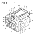
- FIGS. 8 to 15 a further embodiment of the present invention is described with reference to FIGS. 8 to 15 .
- a locking structure of the present invention is applied to a locking structure for inseparably locking a pair of connectors F, M (female connector F, male connector M) properly connected with each other.
- This locking structure is designed to inseparably lock a male housing 150 (corresponding to a preferred other member) of the male connector M properly connected with a female housing 110 (corresponding to a preferred one member) of the female connector F by a spring or resilient member 140 mounted or mountable on the female housing 110.
- sides of the two connectors to be connected are respectively referred to as front sides and reference is made to FIG. 8 concerning upper and lower sides.
- the male connector M includes a male housing 150 and one or more male terminals 151 held in this male housing 150.
- the male housing 150 is made e.g. of synthetic resin and includes a front receptacle 152 and a rear receptacle 153 (preferably substantially in the form of rectangular or polygonal or round or elliptic tubes slightly longer in a width direction), the front receptacle 152 having an open front side and the rear receptacle 153 having an open rear side.
- male terminals 151 are provided (preferably substantially side by side in the width direction at one or more stages) and held while penetrating a back wall 154 (wall between the front receptacle 152 and the rear receptacle 153) of the male housing 150. Front and rear parts of the (three) male terminals 151 respectively at least partly project forward and backward in the front receptacle 152 and the rear receptacle 153.
- One or more engaging projections 155 (corresponding to preferred engageable portions) projecting laterally or outward (preferably to left and/or right) are provided on the (preferably substantially opposite) lateral (left and/or right) surface(s) of the male housing 150.
- the engaging projections 155 are arranged at intermediate positions (preferably substantially at central positions) of the male housing 150 in forward and backward directions, and/or the height positions thereof are located at an vertically intermediate position (preferably substantially in the vertical center) of the female housing 150.
- the front surfaces of the engaging projections 155 preferably are moderately inclined upwardly or outwardly from the front side toward the rear side so that the spring 140 can easily move onto the engaging projections 155, whereas the rear surfaces thereof serve as engageable surfaces 155A engageable with the spring 140.
- the female connector F includes the female housing 110 made e.g. of synthetic resin and connectable with the male housing 150.
- the female housing 110 includes a terminal accommodating portion 111 capable of at least partly accommodating one or more female terminals 134 and an outer tube portion 112 at least partly, preferably substantially fully surrounding the outer circumferential surface of the terminal accommodating portion 111.
- the terminal accommodating portion 111 preferably substantially is in the form of a rectangular column at least partly fittable into the front receptacle 152 of the male housing 150 and/or preferably having a cross section slightly longer in the width direction, and one or more, e.g. three, cavities 113, into which the female terminals 134 are at least partly insertable from an insertion side, preferably substantially from behind, are formed preferably substantially side by side in the terminal accommodating portion 111 at one or more stages.
- the outer tube portion 112 preferably has a substantially tubular shape as a whole and preferably extends from the rear end towards or to the front end of the terminal accommodating portion 111, and the rear end of the outer tube portion 112 and the rear end of the terminal accommodating portion 111 are connected by a connecting portion 114. Between the outer tube portion 112 and the terminal accommodating portion 111 preferably is defined a clearance, into which the front receptacle 152 of the male housing 150 is at least partly insertable.
- a seal ring 115 preferably is to be fitted or mounted on (preferably a rear part of) the outer circumferential surface of the terminal accommodating portion 111, and sealing preferably is provided between the two housings by the seal ring 115 squeezed between the front receptacle 152 and the terminal accommodating portion 111.
- An opening 112A used to assemble a retainer 135 for retaining the female terminals 134 into the terminal accommodating portion 111 is formed in the lower surface of the outer tube portion 112.
- One or more, preferably a pair of finger placing portions 116 projecting sideways from the (preferably substantially opposite) lateral (left and/or right) surface(s) are provided preferably at or near a rear end portion of the female housing 110. Fingertips can be placed on the (both) finger placing portion(s) 116 to operate the female housing 110 (e.g. pull the female housing 110 out) upon separating the both connectors F, M.
- One or more, preferably a pair of standing walls 117 extending substantially in forward and backward directions are provided on the outer or lateral or upper surface of the outer tube portion 112.
- the standing walls 117 preferably substantially continuously extend from the rear end of the female housing 110 towards or to a position near the front end thereof.
- An unlocking arm 125 is at least partly provided between the standing walls 117. The unlocking arm 125 is described in detail later.
- a part of the upper surface of the outer tube portion 112 (preferably adjacent to or between the standing wall(s) 117) preferably is recessed from an intermediate position (preferably a substantially central position) in forward and backward directions towards or to the rear edge, thereby forming a rear recess 118.
- the depth of the rear recess 118 preferably is gradually increased toward the back side.
- first positioning walls 119 are provided on the (preferably substantially opposite) lateral (left and/or right) surface(s) of the outer tube portion 112.
- the first positioning walls 119 preferably are substantially circumferential walls extending substantially along the (preferably substantially opposite) side surface(s) of the outer tube portion 112 from the front ends of the pair of standing walls 117.
- At least one second positioning wall 121 is provided on the outer tube portion 112 preferably before or adjacent to the first positioning walls 119.
- the second positioning wall 121 preferably is a substantially circumferential wall preferably extending over the upper surface and the opposite side surfaces of the outer tube portion 112.
- the second positioning wall 121 and the first positioning walls 119 preferably are substantially parallel to each other, and/or a space having a dimension substantially equal to the width (diameter) of the spring 140 in forward and backward directions is defined therebetween.
- a front recess 122 into which the front end portion of the unlocking arm 125 at least partly escapes or can escape, is formed in a widthwise intermediate position (preferably substantially in the widthwise center) of the second positioning wall 121 (part substantially facing the unlocking arm 125) by recessing.
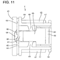
- the front recess 122 preferably is so formed as to be gradually deeper from the opposite widthwise ends thereof toward the center thereof, and its depth in an intermediate part (preferably substantially in a central part) preferably is less than about 2/3, more preferably is about half the thickness (width in forward and backward directions) of the second positioning wall 121 (see FIG. 11 ).
- a part of the outer tube portion 112 between the first positioning walls 119 and the second positioning wall 121 serves as a mounting portion 123, on which the spring 140 is at least partly mounted.
- the mounting portion 123 preferably is formed by an inwardly recessed part of the outer circumferential surface of the outer tube portion 112, the first positioning walls 119 and the second positioning wall 121.
- One or more passages 133 in which the one or more engaging projections 155 of the male housing 150 can pass, are formed in the (preferably substantially opposite) lateral (left and/or right) wall(s) of the outer tube portion 112. Each passage 133 extends substantially backward from the front end of the outer tube portion 112 and/or communicates with the mounting portion 123.
- One or more upper surfaces 124A and/or one or more lower surfaces 124B of communicating portions 124 (corresponding to preferred entrances for leg portions 141 to the passages 133) substantially communicating the mounting portion 123 and the passages 133 preferably are inclined to approach each other from the outer side (mounting portion 123 side) toward the inner side, and/or a vertical dimension of the communicating portions 124 at the inner sides preferably is substantially equal to that of the engaging projections 155 (see FIG. 13 ).
- the upper surfaces 124A of the communicating portions 124 are inclined to guide engaging portions 143 of the spring 140 from the mounting portion 123 toward the passages 133.
- the upper surfaces 124A of the communicating portions 124 correspond to preferred guiding tapered portions.
- the spring 140 mounted on or to the mounting portion 123 of the female housing 110 preferably has a substantially U-shape with an open or lateral bottom side as a whole and preferably includes at least one pair of leg portions 141 resiliently displaceable in directions substantially facing each other and an upper side portion 142 connecting the upper ends of the leg portions 141.
- the pair of leg portions 141 extend substantially vertically downward (or substantially along a moving direction of the spring 140) with respect to the upper side portion 142 from or near the opposite ends of the upper side portion 142 in a nature or undeflected state.
- the engaging portions 143 preferably include upper or closer inclined sides 143A inclined inwardly toward each other and lower or distal inclined sides 143B, and are shaped to have a smaller width or extension in a vertical direction toward the inner side as a whole.
- the lower inclined sides 143B preferably have substantially the same inclinations as the lower surfaces 124B of the communicating portions 124, and/or the upper inclined sides 143A preferably have substantially the same inclinations as the upper surfaces 124A of the communicating portions 124.
- the projecting ends (boundaries between the upper or closer inclined sides 143A and the lower or distal inclined sides 143B) of the engaging portions 143 preferably are rounded.
- the spring 140 is so mounted as to be displaceable between an inserted position IP (see FIG. 13 ) where the engaging portions 143 at least partly project into the passages 133 and a retracted position RP (see FIG. 14 ) where the engaging portions 143 are retracted from the passages 133.
- the spring 140 is at the inserted position IP, the engaging portions 143 at least partly projecting into the passages 133 are pressed by the engaging projections 155 passing the passages 133, whereby the leg portions 141 are resiliently deformed outwardly.
- the leg portions 141 are resiliently at least partly restored to engage the engaging portions 143 with the engageable surfaces 155A to inseparably lock the male housing 150.
- the spring 140 reaches the retracted position RP by being displaced radially outward or upward (direction substantially away from the female housing 110) from the inserted position IP.
- the engaging portions 143 are substantially retracted from the passages 133 to cancel the locked state.
- the engaging portions 143 substantially retracted from the passages 133 preferably are located at the outer sides of the upper surfaces 124A of the communicating portions 124.
- the heights of the first and second positioning walls 119, 122 preferably are so set as to be located before and after the spring 140 over a displaceable range of the spring 140 between the inserted position IP and the retracted position RP.
- the unlocking arm 125 provided adjacent to the one or more standing walls 117, preferably at least partly between the pair of standing walls 117, extends substantially in forward and backward directions (connecting direction with the male housing 150) and/or is connected to the standing walls 117 via one or more, preferably a pair of connecting rotary or pivotal shafts 126 provided substantially in the width direction so as to be lifted up from the outer tube portion 112.
- the unlocking arm 125 has such a length as to project from the rear end of the female housing 110 (or close thereto) towards or to the front recess 122 of the second positioning wall 121, and/or the connecting rotary shafts 126 are provided at substantially lengthwise intermediate (preferably substantially central) positions of the unlocking arm 125 (see FIG. 11 ).
- the connecting rotary or pivotal shafts 126 are shaped to be rotatable or pivotable about an axial line extending in a substantially facing direction of the standing walls 117 (shorter-side direction of the unlocking arm 125), and the unlocking arm 125 preferably is inclinable like a seesaw with the connecting rotary shafts 126 as supporting points.
- the connecting rotary shafts 126 extend slightly obliquely forward from the side surfaces of the unlocking arm 125 to be connected with the standing walls 117. When the unlocking arm 125 is in the natural state, it is substantially parallel to the upper surface of the outer tube portion 112 (see FIG. 8 ).
- a front end portion (one end) of the unlocking arm 125 preferably serves as a pressing portion 127 located below (or under or radially inside) the spring 140 and pressing the spring 140 upward or outward (direction away from the female housing 110) when the unlocking arm 125 is inclined.
- a front wall portion 128 standing or projecting outward or upward is provided at or near the front end of the unlocking arm 125, and the pressing portion 127 is deflected downwardly or inwardly, i.e. toward a side toward which the spring 140 is pressed upon pressing the spring 140 upward our outward, by this front wall portion 128.
- the front wall portion 128 at least partly enters the front recess 122 of the second positioning wall 121, and the rear surface of the front wall portion 128 and that (surface facing the first positioning walls 119) of the second positioning wall 121 preferably are substantially in flush when the unlocking arm 125 is in a natural state.
- the front wall portion 128 substantially has such a mountain or converging shape that the width thereof is gradually decreased toward the upper end.
- a hook portion 129 projecting backward is provided at the upper end of the front wall portion 128.
- the hook portion 129 is provided preferably substantially in conformity with a substantially widthwise central position of the upper side portion 142 of the spring 140 and/or a projecting distance thereof preferably is less than about 2/3 of the spring 140, more preferably substantially equal to half the width (radius) of the spring 140 in forward and backward directions.
- a clearance (preferably having a dimension substantially equal to the vertical width (diameter) of the spring 140) is defined between the hook portion 129 and the pressing portion 127 and the upper side portion 142 of the spring 140 is or can be at least partly held between the hook portion 129 and the pressing portion 127 preferably with substantially no clearance defined in the vertical direction.
- the spring 140 preferably is substantially entirely held between the first positioning walls 119 and the front wall portion 128, the second positioning wall 121 with substantially no clearance defined in forward and backward directions.
- An unlocking portion 131 for pressing the pressing portion 127 upon being pressed is provided at a rear end portion (other end) of the unlocking arm 125.
- the width of the unlocking portion 131 preferably is wider than a front part of the unlocking arm 125 before the connecting rotary shafts 126 (see FIG. 11 ), and/or a rear end part of the upper surface of the unlocking portion 131 serves as a pressable slant 132 inclined gradually upward toward the rear side (see FIG. 8 ).
- the lower surface of the unlocking portion 131 is inclined upward or outward toward the rear end, in other words, the unlocking portion 131 preferably is shaped to reduce its thickness in the vertical direction toward the rear end.
- the spring 140 When the unlocking arm 125 is in the natural or undeflected state, the spring 140 is held or positioned at the inserted position IP and the female housing 110 is in a state lockable with the female housing 150. A state of the unlocking arm 125 at this time is called a lockable state.
- the unlocking portion 131 When the unlocking portion 131 is pressed to incline the unlocking arm 125, the pressing portion 127 presses the spring 140 upward or outward and the spring 140 is displaced towards or to the retracted position RP, i.e. the locked state with the male housing 150 is canceled.
- This state of the unlocking arm 125 is called an unlocking state (see FIGS. 14 and 15 ).
- the unlocking arm 125 is normally set in the lockable state, and the spring 140 is normally set at the inserted position IP.
- the female housing 110 is operated (e.g. gripped by fingers) and gradually pushed into or displaced with respect to the male connector M while the one or more passages 133 of the female housing 110 are positioned with respect to the one or more engaging projections 155 of the male housing 150. Then, the engaging projections 155 move forward in the passages 133 and the front surfaces thereof come substantially into contact with the engaging portions 143 of the spring 140. As the engaging projections 155 further move forward, the engaging portions 143 of the spring 140 move onto the engaging projections 155 and the leg portions 141 are resiliently displaced outwardly (in directions substantially away from each other). At this time, since the hook portion 129 of the unlocking arm 125 is located above (or outside of) the spring 140, the spring 140 can be prevented from being lifted upward or outward upon the resilient displacements of the leg portions 141.
- the two connectors F, M locked in the properly connected state may be separated.
- fingertips are placed on the pressable slant 132 of the unlocking arm 125 in the lockable state to press the unlocking portion 131 downward or inwardly.
- the connecting rotary or pivot shafts 126 rotate or pivot and function as the supporting points, whereby the unlocking arm 125 is inclined and the pressing portion 127 presses the spring 140 upward or outward.
- the spring 140 is pressed upward or outward (or towards the retracted position RP)by the pressing portion 127, the engaging portions 143 are guided outwardly along the inclinations of the upper surfaces 124A of the communicating portions 124 and the leg portions 141 are resiliently deformed away from each other.
- the engaging portions 143 are located at the upper ends of the upper surfaces 124A of the communicating portions 124 to be substantially retracted from the passages 133, and the engaging projections 155 can move backward, i.e. are freed from the locked state. Then, fingers are placed on the finger placing portions 116 of the female housing 110 to preferably hold the female housing 110 from the substantially opposite sides and to pull it backward, whereby the two connectors F, M are separated.
- the unlocking portion 131 is provided at the rear end portion (rear end portion in the connecting direction with the male connector M) of the unlocking arm 125.
- the operability of the unlocking operation is good since the spring needs not be directly displaced with the fingertips, and the locked state can be canceled without requiring labor and time regardless of the shape of the mating male housing. As a result, lock-related operations can be easily performed.
- the unlocking arm 125 resiliently returns to release a force for pressing or displacing the spring 140 down or inwardly and the engaging portions 143 are pressed against the upper surfaces 124A of the communicating portions 124 by resilient restoring forces of the leg portions 141. Then, the engaging portions 143 are substantially guided into the passages 133 by the inclinations of the upper surfaces 124A of the communicating portions 124 and, accordingly, the spring 140 is displaced from the retracted position RP towards or to the inserted position IP.
- the spring 140 preferably is automatically set to the inserted position IP only by moving the fingertips away from the unlocking portion 131. Therefore, the spring 140 needs not be set to the inserted position IP again upon reconnecting the two connectors F, M after they are separated and time and labor required for locking the connectors F, M in the connected state again can be saved.
- the pressing portion 127 preferably is deflected substantially toward the side, toward which the spring 140 is pressed, upon pressing the spring 140, the separation of the spring 140 from the front end of the unlocking arm 125 during the unlocking operation can be avoided, with the result that the unlocking operation can be reliably performed.
- hook portion 129 of the unlocking arm 125 preferably is arranged above the upper side portion 142 of the spring 140, upward (direction away from the female housing 110) displacement and separation of the spring 140 can be prevented by this hook portion 129.
- the pressing portion 127 of the unlocking arm 125 preferably presses the substantially widthwise central part (between the pair of leg portions 141) of the spring 140, the force for pressing the spring 140 acts in a well-balanced manner and the unlocking operation can be efficiently performed.
- the spring 140 is displaced from the inserted position IP towards or to the retracted position RP to cancel the locked state by pressing the unlocking portion 131. Since the spring 140 needs not be directly operated with the fingertips, operability is good.
- one member 110 includes an unlocking arm 125 extending in a connecting direction with an other member 150 and preferably inclinable like a seesaw.
- One end of this unlocking arm 125 serves as a pressing portion 127 arranged between a spring 140 and the one member 110 to press the spring 140 in a direction away from the one member 110, and the other end thereof serves as an unlocking portion 131 for pressing the pressing portion 127 upon being pressed.
- the locking structure of this embodiment differs from the previous embodiment in the shape of an unlocking arm 170.
- the similar or same construction as the previous embodiment is not repeatedly described by being identified by the same reference numerals.
- This locking structure is, similar to the previous embodiment, for inseparably locking a pair of connectors F, M (female connector F, male connector M) properly connected with each other by at least one spring or resilient member 140 mounted on a female housing 110.
- the spring 140 is displaceable between an inserted position IP and a retracted position RP and substantially reaches the retracted position RP by being displaced upward or radially outward from the inserted position IP.
- the unlocking arm 170 (preferably substantially inclinable like a seesaw) is provided adjacent to one or more standing walls 117, preferably at least partly between a pair of standing walls 117, provided on the outer or lateral or upper surface of the female housing 110.
- This unlocking arm 170 preferably is in the form of a substantially rectangular plate long substantially in forward and backward directions as a whole and preferably has such a length as to at least partly project from the rear end of the female housing 110 to a front recess 122 of a second positioning wall 121 similar to the previous embodiment.
- This unlocking arm 170 is arranged substantially at an intermediate position (preferably substantially at a middle position) between the standing walls 117 and is connected to the standing walls 117 via at least one pair of supporting arms 171 provided at the opposite sides.
- the supporting arms 171 preferably are provided for supporting or assisting the unlocking arm 170 in a state lifted up from the female housing 110 and/or are shaped to be long and narrow in an extending direction of the unlocking arm 170 (connecting direction with a male housing 150).
- the supporting arms extend substantially in forward and backward directions at intermediate positions (preferably substantially at middle positions) between the unlocking arm 170 and the standing walls 117, and/or substantially the same clearances preferably are defined at the substantially opposite sides of each supporting arm 171.
- Front end portions (front end portions in the connecting direction with the male housing 150) of the supporting arms 171 are connected with the standing walls 117 at positions near the front ends (positions of the standing walls 117 behind or adjacent to first positioning walls 119), and rear end portions thereof are connected with a rear end portion (unlocking portion 131) of the unlocking arm 170.
- Parts connecting the front end portions of the supporting arms 171 and the standing walls 117 preferably serve as connecting rotary shafts 172 which rotate when the unlocking arm 170 is inclined.
- a front end portion (one end) of the unlocking arm 170 serves as a pressing portion 127 for pressing the spring 140 upward or outward (direction away from the female housing 110) when the unlocking arm 170 is inclined, and a front wall portion 128 and a hook portion 129 are provided at or near the front end of the pressing portion 127.
- a rear end portion (other end) of the unlocking arm 170 serves as the unlocking portion 131 for pressing the pressing portion 127 upon being pressed, wherein a pressable slant 132 is formed on the upper surface of the unlocking portion 131 and/or the lower surface of the unlocking portion 131 is inclined upward or outward toward the rear end.
- One or more supporting point portions 173 serving as supporting points upon an inclining movement of the unlocking arm 170 are provided on a part of the upper surface of the outer tube portion 112 between the standing walls 117.
- the supporting point portions 173 preferably are arranged right below a longitudinal intermediate position (preferably a substantially longitudinal central position) of the unlocking arm 170 (position before or adjacent to a rear recess 118) and project upward from the upper surface of the outer tube portion 112.
- At least one pair of supporting point portions 173 are arranged while being spaced apart in the width direction of the unlocking arm 170 (substantially facing directions of the standing walls 117) and have such a mountain-shaped cross section that the projecting distance gradually increases from the front and rear sides.
- the projecting distances of the supporting point portions 173 are set such that the projecting ends thereof are distanced downward from the lower surface of the unlocking arm 170 when the unlocking arm 170 is in a natural state while coming into contact with the unlocking arm 170 to function as the supporting points upon the inclining movement of the unlocking arm 170 when the unlocking portion 131 is pressed.
- the unlocking arm 170 When being in the natural state, the unlocking arm 170 is substantially parallel to the upper surface of the outer tube portion 112 similar to the previous embodiment. Further, the unlocking arm 170 is in a lockable state when being in the natural state, and is in an unlocking state when being inclined.
- An operation of locking the male connector M and the female connector F in a properly connected state is performed similar to the previous embodiment.
- An operation of separating the two connectors F, M locked in the properly connected state is performed by operating the unlocking arm 170 similar to the previous embodiment and is specifically performed as follows.
- the connecting rotary shafts 172 rotate or pivot to incline the supporting arms 171 in such a manner as to bring the rear ends (sides toward the unlocking portion 131) of the supporting arms 171 downward. Then, as the supporting arms 171 are inclined, the entire unlocking arm 170 is displaced downward or inwardly (toward the outer tube portion 112) and the lower surface of the unlocking arm 170 touches or comes substantially into contact with the supporting point portions 173.
- the unlocking arm 170 is inclined with the supporting point portions 173 as supporting points and the pressing portion 127 presses the spring 140 upward, thereby canceling the locked state similar to the previous embodiment.
- the female housing 110 is or can be pulled backward to separate the two connectors F, M.
- the locked state is canceled by pressing the unlocking portion 131 similar to the previous embodiment, wherefore the unlocking operation can be easily performed.
- This unlocking arm 170 is inclined like a seesaw with the supporting point portions 173 provided separately from the connecting rotary shafts 172 as supporting points.
- the supporting point portions functioning as the supporting points upon the inclining movement of the unlocking arm need to have strength capable of sustaining the force for pressing the pressing portion upward or outward (i.e. force for displacing the spring upward or towards the retracted position RP).
- the connecting rotary shafts double as the supporting point portions, they need to be enlarged in shape in order to have sufficient strength. Then, the rigidities of the connecting rotary shafts are increased and a correspondingly larger force is required upon pressing the unlocking portion.
- the rigidities of the connecting rotary shafts 172 can be reduced by separately providing the supporting point portions 173 and the connecting rotary shafts 172 as in the further (present) embodiment, with the result that the force required to press the unlocking portion 131 can be reduced. Therefore, the unlocking operation can be easily performed.
- FIGS. 22 to 32 a further preferred embodiment of the present invention is described with reference to FIGS. 22 to 32 .
- a locking structure of a preferred embodiment of the present invention is applied to a locking structure for inseparably locking a pair of connectors F, M (female connector F, male connector M) substantially properly connected with each other.
- This locking structure is designed to inseparably lock a male housing 250 (corresponding to a preferred other member) of the male connector M properly connected with a female housing 210 (corresponding to a preferred one member) of the female connector F by a spring 230 mounted or mountable on or to or in the female housing 210.
- sides of the two connectors F, M to be connected are respectively referred to as front sides and reference is made to FIG. 22 concerning upper and lower sides.
- the male connector M particularly is directly connected with a device (such as an automotive junction box, an instrument panel or the like), and the male housing 250 includes a front receptacle 252A projecting substantially forward from an outer wall 251 of the device and a rear receptacle 252B projecting substantially backward.
- the two receptacles 252A, 252B preferably are substantially in the form of rectangular or polygonal or oval or rounded or elliptical tubes, the receptacle 252A having an open front side and the rear receptacle 252B having an open rear side.
- One or more male terminals 254 are held while penetrating a back wall 253 (wall between the front receptacle 252A and the rear receptacle 252B) of the male housing 250. Front and rear parts of the male terminals 254 respectively at least partly project substantially forward and backward in the front receptacle 252A and the rear receptacle 252B.
- the outer wall 251 of the device projects from the outer circumferential surface of the female housing 210 ovar at least part of the circumference, preferably over the substantially entire circumference.
- One or more engaging projections 255 (corresponding to preferred engageable portions) projecting to laterally (left and/or right) are provided on the (preferably substantially opposite) lateral (left and/or right) surface(s) of the male housing 250.
- the one or more engaging projections 255 are arranged at one or more intermediate positions (preferably at substantially at central positions) of the male housing 250 in forward and backward directions, and the height position(s) thereof preferably is/are located substantially in the vertical center of the female housing 250.
- the front surfaces of the engaging projections 255 are moderately inclined upwardly from the front side toward the rear side so that the spring 230 can easily move onto the engaging projections 255, whereas the rear surfaces thereof serve as engaging surfaces 255A engageable with the spring 230 in forward and backward directions.
- the female connector F includes the female housing 210 made e.g. of synthetic resin and connectable with the male housing 250.
- the female housing 210 includes a terminal accommodating portion 212 capable of at least partly accommodating one or more female terminals 211 and an outer tube portion 213 at least partly surrounding the outer circumferential surface of the terminal accommodating portion 212.
- the terminal accommodating portion 212 preferably is substantially in the form of a (preferably rectangular or polygonal or round or oval or elliptic) column at least partly fittable or insertable into the front receptacle 252A of the male housing 250 and/or preferably having a slightly vertically longer (rectangular or polygonal or round or oval or elliptic) cross section.
- the outer tube portion 213 preferably has a substantially tubular shape as a whole and/or substantially extends from the rear end (or close thereto) towards or to the front end of the terminal accommodating portion 212, and the rear end of the outer tube portion 213 and the rear end of the terminal accommodating portion 212 are connected by a connecting portion 215.
- a seal ring 216 preferably is fitted or mounted or mountable on the terminal accommodating portion 212, preferably on or near a back side of the outer circumferential surface of the terminal accommodating portion 212. Sealing preferably is provided between the two housings 210, 250 by the seal ring 216 squeezed or deformed preferably between the front receptacle 252A of the male housing 250 and the terminal accommodating portion 212 of the female housing 210.
- At least one finger placing portion 217 projecting outward from the outer circumferential surface is provided at or near a rear end portion of the female housing 210.
- One or more fingers can be placed on this finger placing portion 217 to operate the female housing 210, preferably to pull the female housing 210 out upon separating the both connectors F, M.
- One or more, preferably a pair of standing walls 218 extending substantially in forward and backward directions are provided on the lateral or outer or upper surface of the outer tube portion 213.
- a slider 240 to be described later is slidably mounted to or on the outer tube portion 213, preferably adjacent to the standing wall(s) 218 and/or at least partly between the standing walls 218.
- One or more guide portions 219 are provided on the inner side surfaces (surfaces substantially facing each other) of the pair of standing walls 218.
- the guide portions 219 preferably are substantially in the form of flat plates and project such that the plate surfaces thereof are at an angle different from 0° or 180°, preferably substantially perpendicular to the inner side surfaces of the standing walls 218 (see FIG. 24 ).
- the guide portions 219 are provided at vertical intermediate positions (preferably at substantially vertical central positions) of the standing walls 218 and/or continuous substantially in forward and backward directions along the standing walls 218.
- An engaging window 221 is formed at an intermediate position (preferably at a substantially central position) of the (preferably each) guide portion 219 in forward and backward directions.
- the engaging window 221 is formed at a position of the guide portion 219 near the standing wall 218, preferably has a substantially rectangular shape narrow and long along the standing wall 218 and/or vertically (in a thickness direction) penetrates the guide portion 219.
- One or more escaping recesses 222 are formed in parts of the lateral or outer or upper surface of the outer tube portion 213 substantially facing the guide portions 219 (see FIG. 22 ).
- the escaping recesses 222 preferably are formed to extend from the rear edge of the female housing 210 (or close thereto) towards or to positions slightly before the front edge positions of the engaging windows 221, and preferably are recessed by a projecting distance of projections 244 of the slider 240 to be described later.
- the depth of each escaping recess 222 preferably is gradually reduced from a part facing the engaging window 221 toward the front side.
- one or more, preferably a pair of backlash preventing ribs 223 extending substantially in forward and backward directions are provided on a part of the lateral or outer or upper surface of the outer tube portion 213 between the standing walls 218 (see FIG. 24 ).
- first positioning walls 218A are provided on the (preferably substantially opposite) lateral (left and/or right) surface(s) of the outer tube portion 213.
- the first positioning walls 218A preferably substantially are circumferential walls extending along the (preferably substantially opposite) side surface(s) of the outer tube portion 213 preferably from the front ends of the pair of standing walls 218.
- At least one second positioning wall 228 is provided on the outer tube portion 213 before or adjacent to the first positioning walls 218A.
- the second positioning wall 228 preferably is a wall substantially extending in a circumferential direction of the outer tube portion 213.
- the second positioning wall 228 and the first positioning walls 218A preferably are substantially parallel to each other, and/or a space having a dimension substantially equal to the width (diameter) of the spring 230 in forward and backward directions preferably is defined therebetween.
- An insertion hole 228A through which the slider 240 to be described later is at least partly insertable, is formed in a widthwise intermediate part (preferably in a substantially widthwise central part) of the second positioning wall 228.
- the insertion hole 228A preferably has a (preferably substantially rectangular) shape longer in a width direction and penetrates the second positioning wall 228 substantially in forward and backward directions (see FIG. 28 ).
- a portion (preferably an upper edge portion) of the second positioning wall 228 at least partly above the insertion hole 228A preferably serves as a lift preventing portion 227 for preventing the lift of (preferably a front end portion of) the slider 240, and is located above the slider 240 (side of the slider 240 opposite to the female housing 210).
- a part of the outer tube portion 213 between the first positioning walls 218A and the second positioning wall 228 preferably serves as a mounting portion 224, on which the spring 230 is mounted.
- the mounting portion 224 preferably is formed by an inwardly recessed part of the outer circumferential surface of the outer tube portion 213, the first positioning walls 218A and the second positioning wall 228.
- One or more passages 225 in which the engaging projections 255 of the male housing 250 can pass, are formed in the (preferably substantially opposite) lateral (left and/or right) wall(s) of the outer tube portion 213. Each passage 225 extends substantially backward from the front end of the outer tube portion 213 and/or communicates with the mounting portion 224.
- One or more upper surfaces 226A and/or lower surfaces 226B of communicating portions 226 (corresponding to preferred entrances for leg portions 231 to the passages 225) substantially communicating the mounting portion 224 and the passages 225 are inclined preferably to approach each other from the outer side (mounting portion 224 side) toward the inner side, and/or a vertical dimension of the communicating portions 226 at the inner sides preferably is substantially equal to that of the engaging projections 255 (see FIG. 23 ).
- the lower surfaces 226B of the communicating portions 226 are inclined to guide engaging portions 233 of the spring 230 from the mounting portion 224 toward the passages 225, and correspond to guiding tapered portions of the present invention.
- the spring 230 is mounted or mountable on the mounting portion 224 (position at a front side of the female housing 210 in a connecting direction with the male housing 250).
- the spring preferably has a substantially W- or U-shape with an open bottom side as a whole and includes at least one pair of leg portions 231 resiliently displaceable in directions substantially facing each other and an upper side portion 232 connecting (preferably the upper ends of) the leg portions 231.
- the pair of leg portions 231 extend substantially vertically downward (or substantially in a direction of displacement of the spring 230) with respect to the upper side portion 232 from the opposite ends of the upper side portion 232 in a nature state.
- Bottom or distal end parts of the leg portions 231 are bent to have substantially converging or pointed or triangular shapes converging or pointed inwardly (substantially in directions toward each other), and these bent parts serve as the engaging portions 233 at least partly projecting into the passages 225.
- the engaging portions 233 include upper or closer inclined sides 233A inclined inwardly toward each other and lower or distal inclined sides 233B, and are shaped to have a smaller width or extension in a vertical direction toward the inner side as a whole.
- the projecting ends (boundaries between the upper inclined sides 233A and the lower inclined sides 233B) of the engaging portions 233 preferably are rounded.
- the spring 230 is so mounted as to be displaceable between an inserted position IP (see FIG. 23 ) where the engaging portions 233 at least partly project into the passages 225 and a retracted position RP (see FIG. 22 ) where the engaging portions 233 are substantially retracted from the passages 225.
- IP inserted position
- RP retracted position
- the engaging portions 233 projecting into the passages 225 are pressed by the engaging projections 255 passing the passages 225, whereby the leg portions 231 are resiliently deformed outwardly.
- the leg portions 231 are resiliently at least partly restored to engage the one or more engaging portions 233 with one or more respective engaging surfaces 255A to inseparably lock the male housing 250.
- the spring 230 substantially reaches the retracted position RP by being displaced downward (direction toward the female housing 210) from the inserted position IP.
- the engaging portions 233 are substantially retracted from the passages 225 and located at or near the outer sides of the lower surfaces 226B of the communicating portions 226 to cancel the locked state.
- the slider 240 slidable substantially in forward and backward directions is assembled into or onto or to the female housing 210.
- the slider 240 includes a main body 241 (preferably substantially long in forward and backward directions) and one or more guiding ribs 242 provided on the (preferably substantially opposite) side surface(s) of the main body 241 (see FIG. 25 ).
- the main body 241 preferably is substantially in the form of a rectangular plate as a whole and/or preferably has a length substantially equal to a distance from the rear end of the female housing 210 to the rear end of the lift preventing portion 227.
- a finger contact portion 243 (preferably substantially in the form of steps climbing or projecting up toward the front) is provided substantially in a central or intermediate part of the main body 241 in forward and backward directions. The slider 240 can be easily slid or operated using this finger contact portion 243 (see FIG. 26 ).
- the one or more guiding ribs 242 preferably are substantially in the form of thin plates projecting sideways from the side surfaces of the main body 241 along the lower surface of the main body 241 and preferably extend from the rear edge of the main body 241 (or close thereto) towards or to front side positions.
- the guiding ribs 242 are to be at least partly inserted into clearances between the outer tube portion 213 of the female housing 210 and the guide portions 219 and/or are slidable in forward and backward directions, whereby the lift of the slider 240 from the female housing 210 preferably can be prevented.
- Each guiding rib 242 is provided with the projection 244 engageable with the engaging window 221.
- the projection 244 projects upward or outward at an intermediate position (preferably at a substantially central position) of the guiding rib 242 in forward and backward directions.
- the projection 244 is shaped to be at least partly fittable into the engaging window 221 and/or slidable substantially in forward and backward directions therein, and the front surface thereof preferably is formed into an inclined surface inclined to project gradually more toward the rear side and the rear surface thereof is formed into a restricting surface 244A to be engaged with (preferably the rear edge of) the engaging window 221 to prevent the slider 240 from being detached backward.
- the projection 244 is provided at or near the rear end of a (preferably substantially cantilever-shaped) engaging piece 245 substantially extending backward along the side edge of the guiding rib 242.
- the slider 240 is to be assembled into or onto or to the female housing 210 from an assembly side, preferably substantially from behind, while resiliently deforming the engaging pieces 245 downward or inward (toward the escaping recesses 222 of the female housing 210).
- one or more backlash preventing ribs 246 extending substantially in forward and backward directions are provided adjacent (before and/or after) the engaging pieces 245.
- Backlash between the slider 240 and the female housing 210 preferably is prevented by the one or more backlash preventing ribs 246 and/or the backlash preventing ribs 223 of the outer tube portion 213.
- the main body 241 is formed with a pressing surface 247 for coming substantially into sliding contact with the upper side portion 232 of the spring 230 to press the upper side portion 232 downward (press or displace the spring 230 towards or to the retracted position RP) according to a sliding operation (see FIG. 27 ).
- the pressing surface 247 preferably is formed in a part of the main body 241 before the guiding ribs 242 and/or inclined upward (direction away from the guiding ribs 242) toward the front end. By forming the pressing surface 247, a front end portion of the main body 241 is thinned toward the front end.
- the slider 240 slides or is displaced in forward and backward directions in a widthwise intermediate part (preferably substantially in a widthwise central part) of the female housing 210 (preferably at least partly between the pair of standing walls 218), and the pressing surface 247 presses a widthwise intermediate part (preferably substantially a widthwise central part) of the upper or outer side portion 232 of the spring 230 (intermediate/central part between the pair of leg portions 231).
- the pressing surface 247 of the slider 240 is located at such a position as substantially not to press the spring 230 and the female housing 210 is in such a state lockable with the male housing 250 (see FIG. 22 ).
- the position of the slider 240 at this time is called a lockable position.
- the pressing surface 247 of the slider 240 presses the spring 230 to displace the spring 230 towards or to the retracted position RP, i.e. to cancel a lock state with the male housing 250 (see FIG. 31 ).
- the position of the slider 240 at this time is called an unlocking position.
- the projections 244 preferably are located at the rear ends of the engaging windows 221 and engaged with the engaging surfaces 255A (see FIG. 29 ) when the slider 240 is at the lockable position, whereas the projections 244 preferably are located at the front ends of the engaging windows 221 (see FIG. 30 ) when the slider 240 is at the unlocking position. Since the engaging windows 221 vertically penetrate, the positions of the projections 244 preferably can be seen, i.e. it can be confirmed (e.g. by the eyes or an external detecting device such as a camera) whether the slider 240 is at the lockable position or at the unlocking position.
- a contact portion 248 projects at the front end of the slider 240.
- the contact portion 248 preferably projects forward from the front edge of the pressing surface 247, i.e. projects forward (connecting direction with the male housing 250) at a side of the upper side portion 232 of the spring 230 substantially opposite to the female housing 210 (see FIG. 22 ).
- the contact portion 248 preferably extends over the substantially entire width of the main body 241 and is located above (or outside of) a part of the upper or outer side portion 232 of the spring 230 preferably having a dimension substantially equal to or longer than about one third of the width of the upper side portion 232 when the slider 240 is at the lockable position (see FIG. 23 ).
- the contact portion 248 preferably projects more forward than the lift preventing portion 227 and is held in contact with the outer wall 251 of the device when the slider 240 is at the unlocking position (see FIG. 31 ).
- the spring 230 is normally set at the inserted position IP, and the slider 240 is normally set at the lockable position.
- the female housing 210 is operated (e.g. gripped by fingers) and gradually pushed or displaced into the male connector M while the passages 225 of the female housing 210 are positioned with respect to the engaging projections 255 of the male housing 250. Then, the engaging projections 255 move forward in the passages 225 and the front surfaces thereof come substantially into contact with the engaging portions 233 of the spring 230. As the engaging projections 255 further move forward, the engaging portions 233 of the spring 230 move onto the engaging projections 255 and the leg portions 231 are resiliently displaced in directions away from each other. At this time, since the contact portion 248 of the slider 240 is located at least partly above the spring 230, the lift of the spring 230 can be prevented upon the resilient displacements of the leg portions 231.
- fingertips are or can be placed on the contact portion 248 of the slider 240 at the lockable position to slide or operate or displace the slider 240 forward.
- the pressing surface 247 comes into sliding contact with the upper side portion 232 of the spring 230 to press the spring 230 downward or inward, and the front end portion of the slider 240 is at least partly inserted below the lift preventing portion 227 (i.e. into the insertion hole 228A).
- the engaging portions 233 preferably are guided outwardly substantially along the inclinations of the lower surfaces 226B of the communicating portions 226 and the leg portions 231 are resiliently deformed away from each other (see FIG. 32 ).
- the engaging portions 233 are located at or near the bottom ends of the lower surfaces 226B of the communicating portions 226 and substantially retracted from the passages 225, whereby the engaging projections 255 can move backward, i.e. are freed from the locked state.
- the contact portion 248 of the slider 240 comes substantially into contact with the outer wall 251 of the device (see FIG. 31 ).
- fingers are or can be placed on the finger placing portion 217 of the female housing 210 to pull the female housing 210 backward while the slider 240 is pressed against the outer wall 251 of the device, whereby the two connectors F, M are separated.
- the pressing surface 247 comes substantially into sliding contact with the spring 230 to press the spring 230 towards or to the retracted position RP, thereby canceling the locked state. Since the spring 230 needs not be directly operated e.g. by fingertips, operability is good. Further, even in a situation where the outer wall 251 of the device stands as a hindrance and the spring 230 cannot be directly pressed down (e.g. with fingertips) as in this embodiment, the locked state can be canceled without any problem. As compared with the case where the unlocking operation is performed using a jig or the like, labor and time required for such an operation can be saved so that overall operability is improved.
- the operability of the unlocking operation is good and the locked state can be canceled without requiring labor and time regardless of the shape of a mating member, with the result that the unlocking operation can be made easier.
- the female housing 210 can be pulled out in a separating direction.
- a connector separating operation can be more easily performed, thus improving overall operability of the locking structure and/or of the connector device provided therewith.
- the force for pressing the spring 230 down is released and the engaging portions 233 are pressed against the lower surfaces 226B of the communicating portion 226 by resilient restoring forces of the leg portions 231. Then, the engaging portions 233 are substantially guided into the passages 225 by the inclinations of the lower surfaces 226B of the communicating portions 226 and, accordingly, the spring 230 is displaced from the retracted position RP towards or to the inserted position IP.
- the spring 230 is automatically set to the inserted position IP only by returning the slider 240 to the initial position IP (lockable position), wherefore the spring 230 needs not be set to the inserted position IP again upon reconnecting the two connectors F, M after they are separated and labor and time required for the connector locking operation can be saved.
- the spring 230 substantially reaches the retracted position RP from the inserted position IP by being displaced in the direction substantially toward the female housing 210.
- the spring 230 can be prevented from being inadvertently separated from the female housing 210 during the unlocking operation.
- the contact portion 248 of the slider 240 is at least partly arranged above or outside of the outer or upper side portion 232 of the spring 230, upward (direction away from the female housing 210) displacements of the spring 230 can be prevented by the contact portion 248.
- displacement and backlash of the spring 230 at the time of connecting the two connectors F, M can be prevented and the connector device can sustain the use under high vibration.
- the slider 240 preferably presses the substantially widthwise central part (between the leg portions 231) of the spring 230, the force for pressing the spring 230 acts in a well-balanced manner and the unlocking operation can be efficiently performed.
- the female housing 210 preferably is provided with the lift preventing portion 227, the lift of the front end portion of the slider 240 during the sliding operation can be prevented. Thus, it is not necessary to press the slider 240 so that the slider 240 will not lift upon pressing the spring 230 down, with the result that the unlocking operation can be easily performed.
- the pressing surface 247 preferably comes substantially into sliding contact with the spring 230 to press the spring 230 to the retracted position RP, thereby canceling the locked state.
- the spring 230 needs not be directly operated with fingertips, wherefore operability is good and the unlocking operation can be easily performed.
- a spring 230 is engaged with one or more engageable portions 255 of an other member 250 (such as the male housing 250) to effect a locked state when being at an inserted position IP, and cancels the locked state by being displaced from the inserted position IP to a retracted position RP.
- a slider 240 (as a preferred movable member) slidable or displaceable substantially in a connecting direction with the other member 250 is assembled into or onto or to one member 210 and formed with at least one pressing surface 247 inclined to be able to press (or displace or interact with) the slider 230 towards or to the retracted position RP when coming into sliding contact with the spring 230 by a sliding operation.
- the locking structure of this embodiment differs from the previous embodiment in that the spring 230 substantially reaches the retracted position RP from the inserted position IP by being displaced upward (direction away from the female housing 210).
- the similar or same construction as the first embodiment is not repeatedly described by being identified by the same reference numerals.
- a pair of connectors F, M (female connector F, male connector M) employing the locking structure according to this embodiment are, similar to the previous embodiment(s), designed to inseparably lock the female connector F and the male connector M by at least one spring 230 including a pair of resiliently displaceable leg portions 231.
- the spring 230 is mounted on or to a mounting portion 224 of a female housing 210 and displaceable between an inserted position IP where engaging portions 233 at least partly project into passages 225 and a retracted position RP where the engaging portions 233 are substantially retracted from the passages 225.
- the spring 230 reaches the retracted position RP from the inserted position IP by being displaced upward or outward.
- the engaging portions 233 are substantially retracted from the passages 225 to cancel a locked state similar to the previous embodiment(s).
- one or more outer or upper surfaces 226A of communicating portions 226 of the female housing 210 substantially correspond to one or more guiding tapered portions inclined to guide the engaging portions 233 of the spring 230 to the passages 225.
- a slider 290 slidable or displaceable in forward and backward directions (preferably substantially corresponding to a connecting direction with a male housing 250) is assembled into or onto or to the female housing 210 similar to the previous embodiment, wherein the rearmost position in a slidable or moving range is a lockable portion and the foremost position therein is an unlocking position.
- a main body 241 of the slider 290 is formed with at least one pressing surface 291 for interacting (preferably coming substantially into sliding contact) an upper or outer side portion 232 of the spring 230 to press the upper or outer side portion 232 upward or outward (press the spring 230 towards or to the retracted position RP) according to a moving or sliding operation.
- the pressing surface 291 is formed in a part of the main body 241 before one or more guiding ribs 242 and inclined downward (direction toward the guiding ribs 242) toward the front end (see FIG. 34 ).
- a contact portion 248 projects at the front end of the main body 241 similar to the previous embodiment.
- the contact portion 248 is located above the upper side portion 232 of the spring 230 when the slider 290 is at the lockable position (see FIG. 33 ) while projecting forward from a lift preventing portion 227 (front end of the female housing 210) when the slider 290 is at the unlocking position (see FIG. 36 ). Similar to the previous embodiment, this contact portion 248 comes substantially into contact with an outer wall 251 of the male housing 250 after the spring 230 is pressed to the retracted position.
- An operation of locking the male connector M and the female connector F in a properly connected state is performed similar to the previous embodiment.
- An operation of separating the two connectors F, M locked in the properly connected state is performed by sliding or operating or displacing the slider 290 similar to the previous embodiment and is specifically performed as follows.
- Fingertips are or can be placed on a finger contact portion 243 of the slider 290 at the lockable position to slide or operate or move or displace the slider 290 forward. Then, the pressing surface 291 engages or interacts (preferably comes substantially into sliding contact) with the upper side portion 232 of the spring 230 to press or displace the spring 230 upward or outward, the engaging portions 233 preferably are guided substantially outwardly along the inclinations of the upper surfaces 226A of the communicating portions 226 and, accordingly, the leg portions 231 are resiliently deformed away from each other.
- the engaging portions 233 are located at or near the upper ends of the upper surfaces 226A of the communicating portions 226 and/or substantially are retracted from the passages 225, whereby the locked state is canceled.
- the contact portion 248 of the slider 290 comes substantially into contact with the outer wall 251 of the male connector M, fingers are placed on a finger placing portion 217 of the female housing 210 to pull the female housing 210 backward while the slider 290 is or can be pressed against the outer wall 251 similar to the first embodiment, whereby the two connectors F, M are separated.
- FIGS. 33 to 43 a further embodiment of the present invention is described with reference to FIGS. 33 to 43 .
- a locking structure of a preferred embodiment of the present invention is applied to a locking structure for inseparably locking a pair of connectors F, M (female connector F, male connector M) substantially properly connected with each other.
- This locking structure is designed to inseparably lock a male housing 350 (corresponding to a preferred other member) of the male connector M properly connected with a female housing 310 (corresponding to a preferred one member) of the female connector F by at least one spring 340 mounted on or to the female housing 310.
- sides of the two connectors to be connected are respectively referred to as front sides and reference is made to FIG. 33 concerning upper and lower sides.
- the male connector M includes a male housing 350 and one or more male terminals 351 at least partly held or provided in this male housing 350.
- the male housing 350 is made e.g. of synthetic resin and includes a front receptacle 352 and a rear receptacle 353 (preferably substantially in the form of rectangular or polygonal or oval or elliptic tubes slightly longer in a width direction), the front receptacle 352 having an open front side and the rear receptacle 353 having an open rear side.
- One or more e.g.
- three) male terminals 351 are provided preferably substantially side by side in the width direction at one or more stages and held while penetrating a back wall 354 (wall between the front receptacle 352 and the rear receptacle 353) of the male housing 350. Front and rear parts of the three male terminals 351 respectively at least partly project forward and backward in the front receptacle 352 and the rear receptacle 353.
- One or more engaging projections 355 (corresponding to preferred engageable portions) projecting laterally (to left and/or right) are provided on the (preferably substantially opposite) lateral (left and/or right) surface(s) of the male housing 350 (see FIG. 41 ).
- the engaging projections 355 are arranged at intermediate positions (preferably substantially at central positions) of the male housing 350 in forward and backward directions, and/or the height positions thereof are located at a vertically intermediate position (preferably substantially in the vertical center) of the female housing 350.
- the front surfaces of the engaging projections 355 preferably are moderately inclined upwardly from the front side toward the rear side so that the spring 340 can easily move onto the engaging projections 355, whereas the rear surfaces thereof preferably serve as engageable surfaces 356 engageable with the spring 340.
- the female connector F includes the female housing 310 made e.g. of synthetic resin and connectable with the male housing 350.
- the female housing 310 includes a terminal accommodating portion 312 capable of at least partly accommodating one or more female terminals 311 and an outer tube portion 313 at least partly, preferably substantially fully surrounding the outer circumferential surface of the terminal accommodating portion 312.
- the terminal accommodating portion 312 is in the form of a (preferably substantially rectangular) column at least partly fittable or insertable into the front receptacle 352 of the male housing 350 and preferably having a cross section slightly longer in the width direction, and one or more (e.g. three) cavities 314, into which the female terminals 311 are at least partly insertable from an insertion side, preferably substantially from behind, are formed preferably substantially side by side at one or more stages in the terminal accommodating portion 312.
- the outer tube portion 313 preferably has a substantially tubular shape as a whole and/or extends from the rear end to the front end of the terminal accommodating portion 312, and the rear end of the outer tube portion 313 and the rear end of the terminal accommodating portion 312 are connected by at least one connecting portion 315. Between the outer tube portion 313 and the terminal accommodating portion 312 is defined a clearance, into which the front receptacle 352 of the male housing 350 is at least partly insertable.
- a seal ring 316 preferably is fitted or mounted on (preferably a back part of the outer circumferential surface of) the terminal accommodating portion 312, and sealing preferably is provided between the two housings by the seal ring 316 squeezed or deformed between the front receptacle 352 and the terminal accommodating portion 312.
- An opening 313A used to assemble a retainer 338 for retaining the female terminals 311 into the terminal accommodating portion 312 is formed preferably in the lateral or lower surface of the outer tube portion 313.
- One or more, preferably a pair of finger placing portions 317 projecting laterally (to left and/or right) from the (preferably substantially opposite) lateral (left and/or right) surface(s) are provided at or near a rear end portion of the female housing 310. Fingertips can be placed on the (preferably both) finger placing portion(s) 317 to manipulate (preferably pull) the female housing 310 out upon separating the both connectors F, M.
- One or more, preferably a pair of standing walls 318 extending substantially in forward and backward directions are provided on the lateral or outer or upper surface of the outer tube portion 313.
- the standing walls 318 preferably continuously extend from the rear end of the female housing 310 to a position near the front end thereof.
- An unlocking arm 327 to be described later is at least partly provided between the standing walls 318.
- a part of the outer or upper surface of the outer tube portion 313 between the standing walls 318 is recessed from an intermediate position (preferably a substantially central position) in forward and backward directions towards or to the rear edge of the female housing 310, thereby forming a rear recess 319.
- the depth of the rear recess 319 preferably is gradually increased toward the back side.
- first positioning walls 321 (preferably substantially circumferentially) extending along the (preferably substantially opposite) lateral (left and/or right) surface(s) of the outer tube portion 313 from the front ends of the pair of standing walls 318 are provided on the (preferably substantially opposite) side surface(s) of the outer tube portion 313.
- At least one second positioning wall 322 is provided on the outer tube portion 313 before or adjacent to the first positioning walls 321.
- the second positioning wall 322 preferably is a substantially circumferential wall extending over the outer or upper surface and/or the (preferably substantially opposite) side surface(s) of the outer tube portion 313.
- the second positioning wall 322 and the first positioning walls 321 preferably are substantially parallel to each other, and a space having a dimension substantially equal to the width (diameter) of the spring 340 in forward and backward directions is defined therebetween (see FIG.39 ).
- the front recess 323 is so formed as to be gradually deeper from the (preferably substantially opposite) widthwise end(s) thereof toward the center thereof, and its depth in an intermediate part (preferably substantially in a central part) preferably is less than about 2/3, more preferably is about half the thickness (width in forward and backward directions) of the second positioning wall 322.
- a part of the outer tube portion 313 between the first positioning walls 321 and the second positioning wall 322 preferably serves as a mounting portion 324, on which the spring 340 is to be mounted, and this part corresponds to a preferred groove portion.
- the mounting portion 324 is formed by an inwardly recessed part of the outer circumferential surface of the outer tube portion 313, the first positioning walls 321 and the second positioning wall 322.
- One or more passages 325 in which the one or more engaging projections 355 of the male housing 350 can pass, are formed in the (preferably substantially opposite) lateral (left and/or right) wall(s) of the outer tube portion 313.
- the (preferably each) passage 325 preferably extends backward from the front end of the outer tube portion 313 and/or communicates with the mounting portion 324.
- Upper surfaces 326A and/or lower surfaces 326B of communicating portions 326 communicating the mounting portion 324 and the passages 325 preferably are inclined to approach each other from the outer side (mounting portion 324 side) toward the inner side, and/or a vertical dimension of the communicating portions 326 at the inner sides preferably is substantially equal to that of the engaging projections 355 (see FIG. 41 ).
- the upper surfaces 326A of the communicating portions 326 preferably are inclined to guide engaging portions 343 of the spring 340 from the mounting portion 324 toward the passages 325.
- the spring 340 mounted on or to the mounting portion 324 of the female housing 310 preferably has a substantially W- or U-shape with an open bottom side as a whole and includes at least one pair of leg portions 341 resiliently displaceable in directions substantially facing each other and an upper side portion 342 connecting the upper ends of the leg portions 341.
- the pair of leg portions 341 extend substantially vertically downward with respect to the upper side portion 342 from the opposite ends of the upper side portion 342 in a nature state.
- Bottom or distal end parts of the leg portions 341 are bent to have substantially converging or mountain or pointed or triangular shapes converging or pointed inwardly (in directions toward each other), and these one or more bent parts serve as the engaging portions 343 at least partly projecting into the one or more passages 325.
- the engaging portions 343 include upper inclined sides 343A inclined inwardly toward each other and lower inclined sides 343B, and preferably are shaped to have a smaller width or extension in a vertical direction toward the inner side as a whole.
- the projecting ends (boundaries between the upper inclined sides 343A and the lower inclined sides 343B) of the engaging portions 343 preferably are rounded.
- the spring 340 is so to be mounted as to be displaceable between an inserted position IP (see FIG. 41 ) where the engaging portions 343 at least partly project into the passages 325 and a retracted position RP (see FIG. 42 ) where the engaging portions 343 are substantially retracted from the passages 325.
- the spring 340 is at the inserted position IP, the one or more engaging portions 343 at least partly projecting into the one or more respective passages 325 are pressed by the one or more engaging projections 355 passing the passages 325, whereby the leg portions 341 are resiliently deformed outwardly.
- the leg portions 341 are resiliently at least partly restored to engage the engaging portions 343 with the engageable surfaces 356 to inseparably lock the male housing 350.
- the spring 340 reaches the retracted position RP preferably by being displaced upward or outward (direction away from the female housing 310) from the inserted position IP.
- the engaging portions 343 are substantially retracted from the passages 325 to cancel the locked state.
- the engaging portions 343 retracted from the passages 325 are located at or near the outer sides of the upper surfaces 326A of the communicating portions 326.
- the unlocking arm 327 extends substantially in forward and backward directions (connecting direction with the male housing 350) and is connected to the standing walls 318 via one or more, preferably a pair of connecting rotary or pivotal shafts 328 provided at the (preferably substantially opposite) widthwise side(s) (see FIGS. 38 and 39 ).
- the unlocking arm 327 preferably is inclinable like a seesaw with the one or more connecting rotary shafts 328 as supporting points.
- the unlocking arm 327 preferably has such a length as to project from the rear end of the female housing 310 to the front recess 323 of the second positioning wall 322, and/or the connecting rotary shafts 328 preferably are provided at substantially longitudinal central positions of the unlocking arm 327.
- the unlocking arm 327 When the unlocking arm 327 is in a natural state, it preferably is substantially parallel to the upper surface of the outer tube portion 313 (see FIG. 33 ).
- a front end portion (one end) of the unlocking arm 327 preferably serves as a pressing portion 329 located below the spring 340 and pressing the spring 340 upward or outward (direction substantially away from the female housing 310) when the unlocking arm 327 is inclined.
- a front wall portion 331 standing upward is provided at a front end portion of the unlocking arm 327, and the pressing portion 329 is deflected downwardly or inwardly, i.e. toward a side toward which the spring 340 is pressed upon pressing the spring 340 upward, by this front wall portion 331.
- the front wall portion 331 at least partly enters the front recess 323 of the second positioning wall 322, and the rear surface of the front wall portion 331 and that (surface facing the first positioning walls 321) of the second positioning wall 322 preferably are substantially in flush when the unlocking arm 327 is in a natural state.
- the front wall portion 331 substantially has such a mountain or converging shape that the width thereof is gradually decreased toward the upper end.
- At least one bulging portion 332 projecting backward is provided at the upper end of the front wall portion 331.
- a projecting distance of the bulging portion 332 preferably is substantially equal to half the width (radius) of the spring 340 in forward and backward directions.
- the bulging portion 332 is arranged above or outside (at a side of the spring 340 substantially opposite to the pressing portion 329) of a widthwise intermediate or central part (substantially middle part between the pair of leg portions 341) of the upper side portion 342 of the spring 340 (see FIGS. 39 and 41 ).
- the upper surface of the bulging portion 332 is formed into a mount guiding surface 333 inclined downward or inward toward the projecting end, so that the spring 340 can be smoothly mounted on the mounting portion 324.
- the lower surface of the bulging portion 332 is formed into at least one restraining surface 334 for restraining the upper side portion 342 of the spring 340 from above.
- the projecting end of the restraining surface 334 preferably has a substantially arcuate shape projecting slightly downward to press the upper end of the spring 340.
- the bulging portion 332 is integral to or unitary with the unlocking arm 327, and a space preferably having a dimension substantially equal to the vertical width (diameter) of the upper side portion 342 of the spring 340 is defined between the suppressing surface 334 and the pressing portion 329.
- a widthwise central part of the upper side portion 342 of the spring 340 preferably is held between the restraining surface 334 and the pressing portion 329 with substantially no clearance defined in the vertical direction.
- the spring 340 preferably is substantially entirely held between the first positioning walls 321 and the front wall portion 331, the second positioning wall 322 with substantially no clearance defined in forward and backward directions.
- the heights of the first and second positioning walls 321, 322 preferably are so set as to be located before and after the spring 340 even if the spring 340 is displaced between the inserted position IP and the retracted position RP.
- a rear end portion (other end) of the unlocking arm 327 serves as an unlocking portion 335 for pressing the pressing portion 329 upon being pressed.
- the width of the unlocking portion 335 preferably is wider than a part of the unlocking arm 327 before the connecting rotary shafts 328, and a pressable slant 336 inclined gradually upward toward the rear side is formed in the upper surface of the unlocking portion 335.
- the lower surface of the unlocking portion 335 preferably is inclined upward toward the rear end, in other words, the unlocking portion 335 is shaped to reduce its thickness in the vertical direction toward the rear end.
- the spring 340 When the unlocking arm 327 is in the natural state, the spring 340 preferably is held at the inserted position IP and the female housing 310 is in a state lockable with the female housing 350. A state of the unlocking arm 327 at this time is called a lockable state (see FIG. 33 ).
- the unlocking portion 335 When the unlocking portion 335 is pressed to incline the unlocking arm 327, the pressing portion 329 presses the spring 340 upward or outward and the spring 340 is displaced toward or to the retracted position RP, i.e. the locked state with the male housing 350 is canceled.
- This state of the unlocking arm 327 is called an unlocking state (see FIG. 42 ).
- the unlocking arm 327 is normally set in the lockable state, and the spring 340 is normally set at the inserted position IP.
- the female housing 310 is e.g. gripped by fingers and gradually pushed into the male connector M while the one or more passages 325 of the female housing 310 are positioned with respect to the one or more respective engaging projections 355 of the male housing 350. Then, the engaging projection(s) 355 move(s) forward in the passage(s) 325 and the front surface(s) thereof come(s) into contact with the engaging portion(s) 343 of the spring 340. As the engaging projections 355 move forward, the engaging portions 343 move onto the engaging projections 355 and the leg portion(s) 341 is/are resiliently displaced preferably substantially in directions away from each other. At this time, since the bulging portion 332 of the unlocking arm 327 is at least partly located above or outside of the spring 340, the spring 340 can be prevented from being lifted upward or outward upon the resilient displacements of the leg portions 341.
- the spring is held or positioned at least partly between the bulging portion 332 and the pressing portion 329, wherefore vertical and circumferential displacements of the spring 340 relative to the mounting portion 324 are prevented. Since the spring 340 and the engaging projections 355 of the male housing 350 preferably are reliably held engaged by preventing the displacements of the spring 340, locking reliability can be improved.
- the spring 340 preferably is prevented from shaking since being substantially closely held between the restraining surface 334 and the pressing portion 329, and/or the displacement and backlash of the spring 340 in forward and backward directions (longitudinal direction of the female housing 310) are prevented since the spring 340 preferably is substantially closely held between the first positioning walls 321 and the second positioning wall 322. Since relative displacements of the spring 340 and the female housing 310 can be prevented in this way, the two connectors F, M can sustain the use in a high-vibration environment.
- the upward (direction away from the female housing 310) displacement of the spring 340 is prevented by the bulging portion 332 in the widthwise intermediate part (preferably substantially in or near the widthwise central part) of the spring 340 (preferably substantially middle position between the pair of leg portions 341), wherefore the spring 340 can be prevented from making such a displacement that one side thereof (the other side if the bulging portion is, for example, arranged at a position closer to one widthwise side of the spring) is lifted upward from the pressing portion 329.
- the engaging portions 343 preferably are guided outwardly substantially along the inclinations of the upper surfaces 326A of the communicating portions 326 and/or the leg portions 341 are resiliently deformed away from each other.
- the engaging portions 343 are located at the upper ends of the upper surfaces 326A of the communicating portions 326 to be retracted from the passages 325.
- the bulging portion 332 is at least partly provided above or outside of the spring 340, the spring 340 may be separated from the pressing portion due to an excessively strong force for pulling the spring 340 upward.
- the bulging portion 332 as in this embodiment, such a separation of the spring 340 can be prevented.
- the pressing portion 329 preferably is deflected toward the side, toward which the spring 340 is pressed, upon pressing the spring 340, the separation of the spring 340 from the pressing portion 329 during the unlocking operation can be avoided.
- the pressing portion 329 of the unlocking arm 327 preferably presses the substantially widthwise central part of the spring 340, the force for pressing the spring 340 acts on the spring 340 in a well-balanced manner and the unlocking operation can be efficiently performed.
- the unlocking arm 327 naturally resiliently at least partly returns to the lockable state to release a force for pressing the spring 340 downward or inward, the engaging portions 343 are pressed against the upper surfaces 326A of the communicating portions 326 by resilient restoring forces of the leg portions 341 and/or guided into the passages 325 by the inclinations of the upper surfaces 326A and, accordingly, the spring 340 is displaced from the retracted position RP towards or to the inserted position IP.
- the spring 340 preferably is automatically set to the inserted position IP only by moving the fingertips away from the unlocking portion 335. Therefore, the spring 340 needs not be set to the inserted position IP again upon reconnecting the two connectors F, M after they are separated and time and labor required for connecting and locking the connectors F, M can be saved. Thus, overall operability is improved.
- the displacement of the spring 340 when the female connector F is left alone can be prevented by providing the bulging portion 332.
- the spring 340 if the spring 340 is displaced when the female connector F is left alone, the spring 340 has to be set to the correct position again upon connecting the female connector F with the male connector M, which requires labor and time.
- the bulging portion 332 as in this embodiment, the displacement of the spring 340 can be prevented, wherefore it is unnecessary to set the spring 340 again and labor and time required for the connector connecting operation can be saved.
- overall operability is improved.
- one member 310 includes an unlocking arm 327 preferably inclinable like a seesaw.
- One end of the unlocking arm 327 serves as a pressing portion 329 arranged between a spring 340 and the one member 310 for pressing the spring 340 in a direction away from the one member 310, and the other end thereof serves as an operable portion 335 for pressing the pressing portion 329 upon being pressed.
- the unlocking arm 327 also includes a bulging portion 332 at a side of the spring 340 opposite to the pressing portion 329.
Landscapes
- Details Of Connecting Devices For Male And Female Coupling (AREA)
- Quick-Acting Or Multi-Walled Pipe Joints (AREA)
Abstract
Description
- The present invention relates to a pair of connectors connectable with each other and to a locking construction.
- There has been conventionally known a connector device to be locked in a properly connected state by the engagement of a lock arm of one connector and a lock projection of the other connector (see, for example, Japanese Unexamined Patent Publication No.
2005-183342 - In the above connector device, a specified clearance is defined between the engaging portion and the locking projection lest the engaging portion and the locking projection should interfere with each other when the lock arm is resiliently restored. Thus, when the connector is subjected to vibration or the like, there may be backlash between the locking projection and the engaging portion, with the result that abnormal noise may be produced or terminals may slide against each other to be abraded. Particularly, in the case of using the connector device in a high-temperature and high-vibration environment, the clearance between the locking projection and the engaging portion may be enlarged due to creep deformation. Therefore, a countermeasure against the backlash is asked for.
- Furthermore, a locking structure, for example, disclosed in Japanese Utility Model Publication No.
H01-98485 - Upon separating the two connectors locked in the properly connected state, the locked state is canceled by pressing the spring down to retract the leg portions from the passages.
- In the above structure, the spring has to be directly pressed down (i.e. unlocking operation) by fingertips. Since the spring is thinner than the fingertips, there is a problem of poor operability.
- If no space sufficient to place the fingertips on the spring can be ensured due to the shape of the mating connector (e.g. the mating connector includes a wall portion projecting more outward than the spring), the unlocking operation has to be performed using a jig or the like, which presents a problem of requiring labor and time for the unlocking operation.
- Moreover, in the above locking structure, the spring may be displaced to inadvertently cancel the locked state, for example, if the connector device is used in a high-vibration environment. However, in order to cancel the locked state, the spring has to be in a displaceable state to a certain extent. Thus, a countermeasure has been asked for.
- The present invention was developed in view of the above situation, and an object thereof is to provide a connector device having an improved overall operability.
- This object is solved according to the invention by the features of the independent claims. Preferred embodiments of the invention are subject of the dependent claims.
- According to one aspect of the invention, there is provided a connector device or assembly, comprising a pair of first and second connectors to be properly connected particularly by at least partly fitting the first connector into the second connector, wherein:
- a spring or resilient member including at least one pair of resiliently displaceable leg portions is mounted on a mounting portion of one housing of the first and second connectors,
- the one housing is formed with one or more passages, into which one or more engageable portions provided on the other housing of the first and second connectors are at least partly insertable upon connecting the pair of connectors,
- the leg portions project into the respective passages via one or more communicating portions communicating the passages and the mounting portion,
- the engageable portions come or can come into contact with the leg portions to move forward in the passages while resiliently displacing the leg portions upon connecting the pair of connectors,
- the rear surfaces of the engageable portions serve as engageable surfaces arranged to substantially face the communicating portions and inclined to produce forces for pushing the other housing forward upon receiving resilient restoring forces of the leg portions when the pair of connectors substantially reach a properly connected state, and
- a fitting portion of the second connector is formed with at least one slanted surface inclined to reduce the width of the fitting portion toward the back side of the fitting portion.
- According to a preferred embodiment of the invention, the slanted surface and the first connector are set to come into contact at a position where a clearance is defined before the first connector in a connecting direction with the second connector.
- According to such a construction, when the pair of connectors reach the properly connected state, the first connector comes or can come substantially into contact with the slanted surface of the second connector with the clearance defined before the first connector and the resiliently at least partly restored leg portions press the engageable surfaces, whereby the housing formed with the engageable surfaces is pushed or displaced forward in the connecting direction. Thus, even if the connector is deformed due to creep or the like, the housing moves forward because of the resilient restoring forces of the leg portions and the first connector is held in contact with the second connector. Therefore, the backlash of the two connectors can be prevented thus improving overall operability.
- A part of the first connector to be brought into contact with the slanted surface of the second connector may be formed with at least one inclined surface inclined substantially in conformity with the slanted surface(s). Thus, the two connectors are held in surface contact, wherefore the backlash can be strongly prevented.
- The spring may be displaceable between an inserted position where the leg portions at least partly project into the passages and a retracted position where the leg portions are substantially retracted from the passages, and/or the communicating portions and/or the leg portions may include one or more guiding portions inclined with respect to a displacing direction of the spring. Thus, the spring can be smoothly displaced.
- The mounting portion may be provided on the outer circumferential surface of the second connector, and at least one pair of circumferentially extending wall portions may be provided before and after the mounting portion on the outer circumferential surface of the second connector. Thus, the spring is mounted between the wall portions, wherefore backlash between the second connector and the spring can be reduced.
- According to the above, there can be provided a connector device capable of preventing backlash.
- According to a further aspect of the invention, there is provided a locking structure for inseparably locking an other member properly connected with one member by at least one spring including at least one pair of resiliently displaceable leg portions and mounted on the one member, wherein:
- the spring is or is to be mounted on a front end portion of the one member in a connecting direction with the other member,
- the spring is to be mounted on the one member is displaceable between an inserted position where the leg portions at least partly project into passages, in which engageable portions of the other member pass, and a retracted position where the leg portions are substantially retracted from the passages,
- the spring is to be engaged with the engageable portions of the other member properly connected with the one member to effect a locked state when the spring is at the inserted position while canceling the locked state by being displaced from the inserted position substantially to or towards the retracted position,
- the spring is to be displaced from the inserted position to or towards the retracted position by being displaced in a direction away from the one member, and
- the one member includes at least one unlocking arm extending substantially in the connecting direction with the other member and substantially inclinable like a seesaw, wherein a front end portion of the unlocking arm in the connecting direction serves as a pressing portion arranged between the spring and the one member for pressing the spring in the direction away from the one member and a rear end portion thereof in the connecting direction preferably serves as an unlocking portion for pressing the pressing portion upon being pressed.
- According to such a construction, the spring is displaced from the inserted position to the retracted position to effect the locked state when the unlocking portion is pressed. Since the spring needs not be directly operated with fingertips, operability is good. Further, since the unlocking portion is provided at the rear end portion of the unlocking arm in the connecting direction with the other member, the locked state can be canceled without any problem even if there is no space to place fingertips on the front end portion of the one member in the connecting direction (end portion where the spring is mounted) due to the shape of the other member or the like. Therefore, as compared with the case where an unlocking operation is performed using a jig or the like, labor and time required for this operation can be saved.
- Since the operability of the unlocking operation and thus overall operability can be improved and labor and time required for this operation can be saved in this way, the unlocking operation can be easily performed.
- The locking structure may comprise a supporting arm extending in the connecting direction with the other member and adapted to support the unlocking arm, a rear end portion of the supporting arm substantially in the connecting direction may be connected with the rear end portion of the unlocking arm in the connecting direction and a front end portion thereof in the connecting direction may be connected with the one member, and one of the unlocking arm and the one member may preferably include a supporting point portion for coming into contact with the other in an intermediate part, preferably substantially in a central part, of the unlocking arm in forward and backward directions when the unlocking portion is pressed to bring the unlocking arm and the one member closer to each other.
- According to such a construction, when the unlocking portion is pressed, the supporting arm is inclined to bring the unlocking arm closer to the one member and the unlocking arm is inclined like a seesaw by the contact with the supporting point portion to cancel the locked state. In other words, since a connecting part connecting the unlocking arm and the one member and the supporting point portion for inclining the unlocking arm like a seesaw are separately provided, the strength of the connecting part can be accordingly reduced. Here, if the connecting part of the unlocking arm and the one member doubles as the supporting point portion for a seesaw-like inclining movement, the connecting part is enlarged to have sufficient strength. Then, the rigidity of the connecting part is increased and a correspondingly large force is required upon pressing the unlocking portion. However, since the rigidity of the connecting part of the one member and the unlocking arm can be reduced according to the construction of the present invention, a smaller force is required for the unlocking operation. As a result, the unlocking operation can be easily performed.
- The locking structure may comprise guiding tapered portions arranged at entrances for the leg portions to the passages, located at sides, toward which the leg portions resiliently return, with respect to engaging portions of the leg portions at least partly projecting into the passages when the spring is at the retracted position, and inclined to guide the engaging portions toward the passages by resilient restoring forces of the leg portions.
- According to such a construction, when the unlocking portion is pressed, the engaging portions are pressed against the guiding tapered portions to be guided into the passages by the resilient restoring forces of the leg portions, and the spring is displaced from the retracted position to the inserted position. Thus, when the pair of members are reconnected and locked after the unlocking operation is performed, the spring needs not be set to the inserted position again, with the result that the locking operation can be easily performed.
- The pressing portion may be shaped to be deflected toward a side, toward which the spring is pressed, when the spring is pressed to move. Thus, upon the unlocking operation, the separation of the spring from the front end of the unlocking arm can be avoided, with the result that the unlocking operation can be reliably performed.
- According to a further aspect of the invention, there is provided a connector device or assembly, in particular according to the first aspect of the invention or a preferred embodiment thereof, comprising a locking structure according to the invention of the above aspect or a preferred embodiment thereof, in which a mating housing as an other member properly connected with a housing as one member is inseparably locked by the spring.
- According to a preferred embodiment of the invention, there is provided a connector device or assembly in which a mating housing properly connected with a housing is inseparably locked by a spring including a pair of resiliently displaceable leg portions and mounted on the housing, wherein:
- the spring is mounted on a front end portion of the housing in a connecting direction with the mating housing,
- the spring mounted on the housing is displaceable between an inserted position where the leg portions project into passages, in which engageable portions of the mating housing pass, and a retracted position where the leg portions are retracted from the passages,
- the spring is engaged with the engageable portions of the mating housing properly connected with the housing to effect a locked state when the spring is at the inserted position while canceling the locked state by being displaced from the inserted position to the retracted position,
- the spring is displaced from the inserted position to the retracted position by being displaced in a direction away from the housing, and
- the housing includes an unlocking arm extending in the connecting direction with the mating housing and inclinable like a seesaw, wherein a front end portion of the unlocking arm in the connecting direction serves as a pressing portion arranged between the spring and the housing for pressing the spring in the direction away from the housing and a rear end portion thereof in the connecting direction serves as an unlocking portion for pressing the pressing portion upon being pressed.
- According to the above, there can be provided a locking structure for locking a pair of members in a properly connected state by a spring and a connector device to be locked in a properly connected state by a spring, the locking structure and the connector device enabling lock-related operations to be easily performed.
- According to a further aspect of the invention, there is provided a locking structure for inseparably locking an other member properly connected with one member by at least one spring including at least one pair of resiliently displaceable leg portions and mountable or mounted on or to or into the one member, wherein:
- the spring is mounted on a front end portion of the one member in a connecting direction with the other member,
- the spring mounted on the one member is displaceable between an inserted position where the leg portions at least partly project into passages, in which one or more engageable portions of the other member pass, and a retracted position where the leg portions are substantially retracted from the passages,
- the spring is engaged with the engageable portions of the other member to effect a locked state when the spring is at the inserted position while canceling the locked state by being displaced from the inserted position to the retracted position,
- a movable member displaceable (preferably being a slider slidable) substantially along or in the connecting direction with the other member is assembled into or to or onto the one member, and
- the movable member (preferably the slider) is formed with at least one pressing surface inclined to be able to press the spring to the retracted position upon being displaced, preferably when coming substantially into sliding contact with the spring by a sliding operation.
- According to such a construction, when the movable member is displaced or moved (preferably when the slider is slid), the pressing surface interacts (preferably comes substantially into sliding contact) with the spring to press or move or displace the spring towards or to the retracted position, thereby canceling the locked state. Since the spring needs not be directly operated with fingertips, operability is good thus improving overall operability. Further, the locked state can be canceled without any problem even if there is no space to place fingertips on the front end portion of the one member in the connecting direction (end portion where the spring is mounted) due to the shape of the other member or the like. Therefore, as compared with the case where an unlocking operation is performed using a jig or the like, labor and time required for this operation can be saved thus improving overall operability.
- Since the operability of the unlocking operation can be improved and labor and time required for this operation can be saved in this way, the unlocking operation can be easily performed.
- A contact portion for coming into contact with the other member substantially in the connecting direction after the spring is displaced or pressed to the retracted position may project from the slider. According to such a construction, after the movable member is displaced (preferably the slider is slid) to cancel the locked state, the one member can be pulled out in a separating direction with the contact portion held in contact with the other member. Thus, an operation of separating the two members can be more easily performed as compared with the case where the one member is pulled out of the other member while being held by fingertips.
- The locking structure may comprise one or more guiding tapered portions arranged at or near entrances for the leg portions to the passages, located at sides, toward which the leg portions resiliently return, with respect to engaging portions of the leg portions at least partly projecting into the passages when the spring is at the retracted position, and preferably inclined to guide the engaging portions toward the passages by resilient restoring forces of the leg portions.
- Then, when the interaction by the movable member (preferably the pressing operation by the slider) is substantially terminated, the engaging portions are pressed against the guiding tapered portions to be substantially guided into the passages by the resilient restoring forces of the leg portions, and the spring is displaced from the retracted position to the inserted position. Thus, when the pair of members are reconnected after being separated by canceling the locked state, the spring needs not be set to the inserted position again, wherefore the locking operation can be easily performed so that overall operability is improved.
- The spring may reach the retracted position from the inserted position by being displaced in a direction toward the one member. Then, a displacing direction of the spring during the unlocking operation is opposite to a separating direction of the spring from the one member, wherefore an inadvertent detachment of the spring from the one member during the unlocking operation can be prevented.
- The contact portion may project substantially in the connecting direction at a side of the spring substantially opposite to the one member. Then, a displacement of the spring toward the side opposite to the one member (i.e. toward the side away from the one member) is prevented, with the result that the detachment of the spring from the one member can be prevented.
- The movable member (preferably the slider) may press a central or intermediate part of the spring between the pair of leg portions. Then, since the movable member (preferably the slider) interacts with or presses the intermediate or substantially widthwise central part (between the pair of leg portions) of the spring, the force for pressing the spring acts in a well-balanced manner and the unlocking operation can be efficiently performed.
- The one member may include at least one lift preventing portion arranged at a side of the slider substantially opposite to the one member. Since the lift of the movable member (preferably the slider) during the movement or sliding operation is prevented by this lift preventing portion, it is not necessary to press the movable member (preferably the slider) so that the movable member (preferably the slider) will not lift and the unlocking operation can be easily performed. Thus, overall operability is improved.
- According to a further aspect of the invention, there is provided a connector device or assembly, in particular according to the previous aspect(s) of the invention or pa preferred embodiment thereof, comprising a locking structure according the invention or a preferred embodiment thereof, in which a mating housing as the other member properly connected with a housing as one member is inseparably locked by the at least one spring.
- According to a preferred embodiment of the invention, there is further provided a connector device or assembly in which a mating housing properly connected with a housing is inseparably locked by a spring including a pair of resiliently displaceable leg portions and mounted on the housing, characterized in that:
- the spring is mounted on a front end portion of the housing in a connecting direction with the mating housing,
- the spring mounted on the housing is displaceable between an inserted position where the leg portions project into passages, in which engageable portions of the mating housing pass, and a retracted position where the leg portions are retracted from the passages,
- the spring is engaged with the engageable portions of the mating housing to effect a locked state when the spring is at the inserted position while canceling the locked state by being displaced from the inserted position to the retracted position,
- a slider slidable in the connecting direction with the other member is assembled into the one member, and
- the slider is formed with a pressing surface inclined to be able to press the spring to the retracted position when being pressed against the spring by a sliding operation.
- According to the above, there can be provided a locking structure for locking a pair of members in a properly connected state by a spring and a connector device to be locked in a properly connected state by a spring, the locking structure and the connector device enabling lock-related operations to be easily performed.
- According to a further apect of the invention, there is provided a locking structure for inseparably locking an other member properly connected with one member by at least one spring including at least one pair of resiliently displaceable leg portions and mounted on or to or onto the one member, wherein:
- the spring is displaceable between an inserted position where the leg portions at least partly project into one or more passages, in which one or more engageable portions of the other member pass, and a retracted position where the leg portions are substantially retracted from the passages, reaches the retracted position from the inserted position by being displaced in a direction away from the one member, and inseparably locks the other member by the engagement of the leg portions with the engageable portions while canceling the locked state by the leg portions being substantially retracted from the passages,
- the one member includes an unlocking arm preferably substantially inclinable like a seesaw, wherein one end of the unlocking arm serves as a pressing portion arranged between the spring and the one member for pressing the spring in the direction substantially away from the one member and the other end thereof serves as an unlocking portion for pressing or displacing the pressing portion upon being pressed, and
- the unlocking arm includes at least one bulging portion at a side of the spring substantially opposite to the pressing portion.
- According to such a construction, when the operable portion of the unlocking arm is pressed, the pressing portion of the unlocking arm presses or displaces the spring in the direction substantially away from the one member to cancel the locked state. The displacement of the spring is prevented since the spring is held at least partly between the bulging portion and the pressing portion. Thus, the locked state can be canceled and the displacement of the spring can be prevented. Thus, a locked state is enabled to be canceled and capable of preventing the displacement of a spring so that overall operability is improved.
- The bulging portion may be provided substantially in correspondence with a substantially middle part of the spring between the pair of leg portions. According to such a construction, the spring has its widthwise central part (substantially middle part between the pair of leg portions) held at least partly between the bulging portion and the pressing portion. Thus, such a displacement of the spring that one side thereof is lifted upward or outward from the pressing portion can be prevented.
- The pressing portion may be shaped to be deflected toward a side, toward which the spring is pressed, when the spring is pressed to move. Then, during an unlocking operation, the spring is pressed against the deflected part of the pressing portion and the separation thereof from the pressing portion can be prevented.
- The spring may be at least partly mounted in a substantially circumferentially extending groove portion formed in the one member. Then, the longitudinal displacement of the spring can be prevented.
- According to a further aspect of the invention, there is provided connector device or assembly, in particular according to one or more above aspects or preferred embodiments thereof, comprising a locking structure according to the above aspect or a preferred embodiment thereof, in which a mating housing as the other member properly connected with a housing as the one member is inseparably locked by the at least one spring.
- According to a further preferred embodiment of the invention, there is provided a connector device in which a mating housing properly connected with a housing is inseparably locked by a spring including a pair of resiliently displaceable leg portions and mounted on the housing, characterized in that:
- the spring is displaceable between an inserted position where the leg portions project into passages, in which engageable portions of the other member pass, and a retracted position where the leg portions are retracted from the passages, reaches the retracted position from the inserted position by being displaced in a direction away from the one member, and inseparably locks the other member by the engagement of the leg portions with the engageable portions while canceling the locked state by the leg portions being retracted from the passages,
- the one member includes an unlocking arm inclinable like a seesaw, wherein one end of the unlocking arm serves as a pressing portion arranged between the spring and the one member for pressing the spring in the direction away from the one member and the other end thereof serves as an unlocking portion for pressing the pressing portion upon being pressed, and
- the unlocking arm includes a bulging portion at a side of the spring opposite to the pressing portion.
- According to the above, there can be provided a locking structure and a connector device enabling a locked state to be easily canceled and capable of preventing the displacement of a spring.
- These and other objects, features and advantages of the present invention will become more apparent upon reading of the following detailed description of preferred embodiments and accompanying drawings. It should be understood that even though embodiments are separately described, single features thereof may be combined to additional embodiments.
-
FIG. 1 is a longitudinal section showing a properly connected state of a connector device according to one embodiment, -
FIG. 2 is an external perspective view of a female connector, -
FIG. 3 is a plan view in section of the female connector, -
FIG. 4 is a plan view in section showing the properly connected state of the two connectors, -
FIG. 5 is a lateral section showing the properly connected state of the two connectors, -
FIG. 6 is a lateral section of the female connector showing a state where a locked state is canceled, -
FIG. 7 is a longitudinal section showing a state where the two connectors are separated, -
FIG. 8 is a longitudinal section showing a state where a connector device according to a further embodiment is locked in a properly connected state, -
FIG. 9 is an external perspective view of a female connector when viewed from front, -
FIG. 10 is an external perspective view of the female connector when viewed from behind, -
FIG. 11 is a plan view of the female connector, -
FIG. 12 is a side view of the female connector, -
FIG. 13 is a lateral section showing a state where the connector device is locked in the properly connected state, -
FIG. 14 is a lateral section showing the female connector in an unlocked state, -
FIG. 15 is a longitudinal section showing a state where two connectors are separated, -
FIG. 16 is an external perspective view showing a female connector according to a still further embodiment when viewed from front, -
FIG. 17 is an external perspective view of the female connector when viewed from behind, -
FIG. 18 is a plan view of the female connector, -
FIG. 19 is a rear view of the female connector, -
FIG. 20 is an external perspective view partly in section showing the female connector, -
FIG. 21 is a longitudinal section of the female connector, -
FIG. 22 is a longitudinal section showing a state where a pair of connectors are locked by a locking structure according to a first embodiment, -
FIG. 23 is a lateral section showing the state ofFIG. 22 , -
FIG. 24 is a lateral section of a female housing, -
FIG. 25 is a plan view of a slider, -
FIG. 26 is a side view of the slider, -
FIG. 27 is a front view of the slider, -
FIG. 28 is a front view of the female housing having a spring mounted thereon, -
FIG. 29 is a plan view in section of the pair of connectors when the slider is at a lockable position, -
FIG. 30 is a plan view in section of the pair of connectors when the slider is at an unlocking position, -
FIG. 31 is a longitudinal section showing a state where a locked state of the pair of connectors is canceled, -
FIG. 32 is a lateral section showing the state ofFIG. 31 , -
FIG. 33 is a longitudinal section showing a state where a pair of connectors are locked by a locking structure according to a second embodiment, -
FIG. 34 is a side view of a slider, -
FIG. 35 is a front view of the slider, -
FIG. 36 is a longitudinal section showing a state where a locked state of the pair of connectors is canceled, -
FIG. 37 is a longitudinal section showing a state where a connector device according to one further embodiment is locked in a properly connected state, -
FIG. 38 is an external perspective view of a female connector, -
FIG. 39 is a plan view of the female connector, -
FIG. 40 is a side view of the female connector, -
FIG. 41 is a lateral section showing a state where two connectors are locked in a properly connected state, -
FIG. 42 is a lateral section showing the female connector in an unlocked state, and -
FIG. 43 is a longitudinal section showing a state where the two connectors are separated. - Hereinafter, one preferred embodiment of the present invention is described with reference to
FIGS. 1 to 7 . - A connector device or assembly according to this embodiment is provided at least with a male connector (corresponding to a preferred first connector) and a female connector 20 (corresponding to a preferred second connector) connectable with each other. In the respective constituent members described below, sides of the two
connectors FIG. 1 concerning upper and lower sides. - The
male connector 10 includes amale housing 11 and one or moremale terminals 12 held at least partly in thismale housing 11. Themale housing 11 is made e.g. of synthetic resin and includes afront receptacle 13 and a rear receptacle 14 (preferably substantially in the form of rectangular tubes slightly longer in a width direction), thefront receptacle 13 having an open front side and therear receptacle 14 having an open rear side. The thickness (dimension in inward and outward directions) of thefront receptacle 13 preferably is smaller in its front portion (preferably substantially front half) than in its rear portion (preferably substantially rear half). One or more engaging projections 16 (corresponding to preferred engageable portions) projecting outwardly or laterally (to left and/or right) are provided on the (preferably substantially opposite) outer or lateral (left and/or right) surface(s) of themale housing 11. The engagingprojections 16 are described in detail later. - One or more (e.g. three)
male terminals 12 are provided preferably substantially side by side in the width direction at one or more stages and held while penetrating a back wall 15 (wall between thefront receptacle 13 and the rear receptacle 14) of themale housing 11. Front and rear parts of the (three)male terminals 12 respectively at least partly project substantially forward and backward in thefront receptacle 13 and therear receptacle 14. - The
female connector 20 includes afemale housing 21 made e.g. of synthetic resin and connectable with themale housing 11. Thefemale housing 21 includes aterminal accommodating portion 23 capable of at least partly accommodating one or morefemale terminals 22 and anouter tube portion 24 at least partly surrounding the outer circumferential surface of theterminal accommodating portion 23. - The
terminal accommodating portion 23 preferably substantially is in the form of a rectangular column at least partly fittable into thefront receptacle 13 of themale housing 11 and/or preferably having a cross section slightly longer in the width direction, and threecavities 25, into which thefemale terminals 22 are at least partly insertable from an insertion side, preferably substantially from behind, are formed preferably substantially side by side in theterminal accommodating portion 23. - The
outer tube portion 24 has a substantially tubular shape as a whole and extends from or at the rear end to the front end of theterminal accommodating portion 23, and the rear end of theouter tube portion 24 and the rear end of theterminal accommodating portion 23 preferably are connected by a connectingportion 26. Between theouter tube portion 24 and theterminal accommodating portion 23 is defined a clearance, into which thefront receptacle 13 of themale housing 11 is at least partly insertable. A part between theouter tube portion 24 and theterminal accommodating portion 23 serves as afitting portion 27, into which themale connector 10 is to be at least partly fitted or inserted. One or morebacklash perverting ribs 49 for preventing backlash between thefront receptacle 13 and theouter tube portion 24, theterminal accommodating portion 23 project at one or more, preferably a plurality of positions on the outer circumferential surface of theterminal accommodating portion 23 and/or the inner circumferential surface of theouter tube portion 24 defining the fitting portion 27 (seeFIG. 6 ). Anopening 24A used to preferably assemble aretainer 48 for retaining thefemale terminals 22 into theterminal accommodating portion 23 is formed preferably in the lateral (lower) surface of theouter tube portion 24. - On the outer circumferential surface of the
terminal accommodating portion 23, aseal ring 28 preferably is fitted or mounted at a position preferably near the rear end. Sealing preferably is provided between thehousings seal ring 28 squeezed or deformed substantially between thefront receptacle 13 and theterminal accommodating portion 23. - One or more, preferably a pair of
finger placing portions 29 projecting outwardly or laterally (to left and/or right) from the (preferably substantially opposite) outer or lateral (left and/or right) surface(s) are provided preferably at or near a rear end portion of thefemale housing 21. Fingertips can be placed on the (preferably both) finger placing portion(s) 29 to pull thefemale housing 21 out upon separating the bothconnectors - One or more, preferably a pair of standing
walls 31 extending substantially in forward and backward directions are provided on the outer or lateral (upper) surface of theouter tube portion 24 while preferably being spaced apart by a specified (predetermined or predeterminable) distance in the width direction. The (pair of) standing wall(s) 31 continuously extend(s) from the rear end of the female housing 21 (or close thereto) to a position near the front end thereof. - One or more
first positioning walls 32 circumferentially extending from the front ends of the pair of standingwalls 31 are provided on the (preferably substantially opposite) side surface(s) of theouter tube portion 24, and at least onesecond positioning wall 33 is provided on theouter tube portion 24 before or adjacent to the first positioning wall(s) 32. Thesecond positioning wall 33 preferably is a circumferential wall extending over the outer (upper) surface and the opposite side surfaces of theouter tube portion 24. Thesecond positioning wall 33 and the first positioning wall(s) 32 preferably are substantially parallel to each other, and/or a space having a dimension substantially equal to the width (diameter) of a spring 50 (as a preferred biasing member) in forward and backward directions is defined therebetween. Thefirst positioning walls 32 and thesecond positioning wall 33 preferably correspond to a pair of wall portions. - A
front recess 34 having an open front side is formed in a widthwise intermediate position (preferably substantially in the widthwise center) of a part of thesecond positioning wall 33 extending substantially along the lateral (upper) surface of theouter tube portion 24. Thefront recess 34 preferably is so formed as to be gradually deeper from the opposite widthwise ends thereof toward the center thereof, and its depth in an intermediate part (preferably substantially in a central part) is less than 2/3, preferably about half the thickness (width in forward and backward directions) of thesecond positioning wall 33. - A part of the
outer tube portion 24 between the first positioning wall(s) 32 and thesecond positioning wall 33 serves as a mountingportion 35, on or to which thespring 50 is mounted. In other words, thefemale housing 21 corresponds to a preferred one housing, and themale housing 11 corresponds to a preferred other housing. The mountingportion 35 is formed by an inwardly recessed part of the outer circumferential surface of theouter tube portion 24, thefirst positioning walls 32 and thesecond positioning wall 33. - One or
more passages 36, in which the engagingprojections 16 of themale housing 11 can pass, are formed in the (preferably substantially opposite) outer or lateral (left and/or right) walls of theouter tube portion 24. Eachpassage 36 preferably is a groove having an open inner side (toward the terminal accommodating portion 23), extends backward from the front end of theouter tube portion 24 and/or communicates with the mountingportion 35. -
Upper surfaces 37A and/orlower surfaces 37B of communicatingportions 37 communicating the mountingportion 35 and thepassages 36 preferably are inclined to approach each other from the outer side (mountingportion 35 side) toward the inner side, and/or a vertical dimension of the communicatingportions 37 at the inner sides preferably is substantially equal to that of the engaging projections 16 (seeFIG. 5 ). - The
spring 50 preferably has a substantially U-shape with an open bottom side as a whole and includes a pair ofleg portions 51 resiliently displaceable in directions substantially facing each other and anupper side portion 52 connecting the upper ends of theleg portions 51. The pair ofleg portions 51 extend at an angle different from 0° or 180°, preferably substantially normal (preferably substantially vertically downward) with respect to theupper side portion 52 from the opposite ends of theupper side portion 51 in a nature or undeflected state. - Bottom or distal end parts of the pair of
leg portions 51 are bent to have substantially pointed or triangular shapes pointed inwardly (in directions toward each other), and these bent parts serve as engagingportions 53 projecting at least partly into thepassages 36 via the communicatingportions 37. The engagingportions 53 include closer or upperinclined sides 53A inclined inwardly toward each other and distal or lowerinclined sides 53B, and are shaped to have a smaller width or extension in a vertical direction (projecting direction) toward the inner side as a whole. The upperinclined sides 53A and the lowerinclined sides 53B preferably have substantially the same inclinations as theupper surfaces 37A and thelower surfaces 37B of the communicatingportions 37. The projecting ends (boundaries between the upperinclined sides 53A and the lowerinclined sides 53B) of the engagingportions 53 preferably are rounded. - The
spring 50 is so mounted as to be displaceable between an inserted position IP (seeFIG. 5 ) where the engagingportions 53 project into thepassages 36 and a retracted position RP (seeFIG. 6 ) where the engagingportions 53 are retracted from thepassages 36. When thespring 50 is at the inserted position IP, the engagingportions 53 at least partly projecting into thepassages 36 are pressed by the engagingprojections 16 passing thepassages 36, whereby theleg portions 51 at least partly are resiliently deformed outwardly. When the twoconnectors leg portions 51 are resiliently at least partly restored to engage the engagingportions 53 withengageable surfaces 16B of the engagingprojections 16 to inseparably lock themale housing 11. - The
spring 50 reaches the retracted position RP by being displaced upwardly (direction away from the female housing 21) from the inserted position IP. When thespring 50 reaches the retracted position RP, the engagingportions 53 are substantially retracted from thepassages 36 to cancel the locked state. The engagingportions 53 retracted from thepassages 36 are located at the outer sides of theupper surfaces 37A of the communicatingportions 37. Theupper surfaces 37A of the communicatingportions 37 and the upperinclined sides 53A of the engagingportions 53 correspond to preferred guiding portions. - A part of the upper surface of the
outer tube portion 24 between the standingwalls 31 is recessed from an intermediate position (preferably substantially a substantially central position) in forward and backward directions to the rear edge of thefemale housing 21, thereby forming a rear recess 38 (seeFIG. 7 ). The depth of therear recess 38 preferably is gradually increased toward the back side. - An unlocking
arm 39 is provided on theouter tube portion 24 between the pair of standingwalls 31. The unlockingarm 39 extends substantially in forward and backward directions (connecting direction with the male housing 11) and is connected to the both standingwalls 31 via one or more, preferably a pair of connectingrotary shafts 41 provided substantially in the width direction so as to be inclinable like a seesaw. - A front end portion (one end) of the unlocking
arm 39 serves as apressing portion 42 located below (or radially inside or under) thespring 50 and pressing thespring 50 upward or radially outward (direction away from the female housing 21) when the unlockingarm 39 is inclined. Afront wall portion 43 standing outward or upward is provided at or near the front end of the unlockingarm 39, and thepressing portion 42 is deflected downwardly or inwardly, i.e. toward a side toward which thespring 50 is pressed upon pressing thespring 50 upward or outward, by thisfront wall portion 43. Thefront wall portion 43 at least partly enters thefront recess 34 of thesecond positioning wall 33, and the rear surface of thefront wall portion 43 and that (surface facing the first positioning walls 32) of thesecond positioning wall 33 preferably are substantially in flush. Thefront wall portion 43 preferably substantially has such a mountain shape that the width thereof is gradually decreased toward the upper end. - A
hook portion 44 projecting backward is provided at or near the upper end of thefront wall portion 43. A projecting distance of thehook portion 44 from thefront wall portion 43 preferably is substantially equal to or more than about half the width (radius) of thespring 50 in forward and backward directions. Thehook portion 44 is arranged above theupper side portion 52 of thespring 50, a clearance preferably having a dimension substantially equal to the vertical width (diameter) of thespring 50 is defined between thehook portion 44 and thepressing portion 42 and theupper side portion 52 of thespring 50 preferably is held at least partly between thehook portion 44 and thepressing portion 42 with substantially no clearance defined in the vertical direction. Thehook portion 44 preferably is located at a position substantially corresponding to a widthwise central part of the spring 50 (central part between the pair of leg portions 51). - The
spring 50 is (preferably substantially entirely) held between thefirst positioning walls 32 and thefront wall portion 43, thesecond positioning wall 33 preferably with substantially no clearance defined in forward and backward directions. The heights of thefirst positioning walls 32 and thesecond positioning wall 33 are set such that thespring 50 is held therebetween over a displaceable range between the inserted position IP and the retracted position RP. - An unlocking
portion 45 for pressing thepressing portion 42 upon being pressed is provided at or near a rear end portion (other end) of the unlockingarm 39. The lower surface of the unlockingportion 45 is inclined outwardly or upwardly toward the rear end (preferably to reduce the thickness of the unlocking portion 45). By the inclination of the lower surface of the unlockingportion 45 and therear recess 38 of thefemale housing 21, a sufficient downward resilient displacement of the unlockingportion 45 is ensured or provided while the height of thefemale housing 21 is suppressed. - When the unlocking
arm 39 is in a natural state, thespring 50 is held or positioned at the inserted position IP and thefemale housing 21 is in a state lockable into thefemale housing 11. A state of the unlockingarm 39 at this time is called a lockable state. When the unlockingportion 45 is pressed to incline the unlockingarm 39, thepressing portion 42 presses or displaces thespring 50 upward or outward and thespring 50 is displaced towards or to the retracted position RP, i.e. the locked state with themale housing 11 is canceled. This state of the unlockingarm 39 is called an unlocking state. - The
fitting portion 27 of thefemale connector 20 is formed with one or moreslanted surfaces 46 inclined to reduce the width of thefitting portion 27 toward the rear side (back side) (inclined in a direction approaching the terminal accommodating portion 23). The slanted surfaces 46 are formed on the inner circumferential surface (surface facing the terminal accommodating portion 23) of theouter tube portion 24. The slanted surfaces 46 are formed at a back end side of thefitting portion 27, more specifically in a range of the inner circumferential surface of theouter tube portion 24 from a position immediately before the connectingportion 26 towards or to a position near the front end of theseal ring 28 fitted on theterminal accommodating portion 23. The slanted surfaces 46 are formed substantially on the inner circumferential surface of theouter tube portion 24 preferably over the substantially entire circumference (specifically, upper, lower, left and right edge portions excluding four corners) to reduce the dimensions of thefitting portion 27 in the vertical and/or transverse directions. The width (distance between theslanted surfaces 46 and the terminal accommodating portion 23) at the back end of thefitting portion 27 preferably is set smaller than the thickness of a front end part of thefront receptacle 13 of themale housing 11. Thus, when the twoconnectors front receptacle 13 comes substantially into contact with theslanted surfaces 46 before the front end of thefront receptacle 13 reaches the back end of thefitting portion 27, whereby a clearance is defined forward (forward in the connecting direction with the female connector 20) of thefront receptacle 13. - The front end part (part to be brought substantially into contact with the
slanted surfaces 46 of the female connector 21) of thefront receptacle 13 is formed with one or moreinclined surfaces 17 substantially in conformity with the inclination(s) of the one or more slanted surfaces 46. The inclined surfaces 17 preferably are formed on the outer circumferential surface of thefront receptacle 13 substantially over the entire circumference. The inclined surfaces 17 are inclined outwardly from the front end of thefront receptacle 13 toward the rear side, and/or the front end part of thefront receptacle 13 is gradually thinned toward the front end by the inclined surfaces 17. Parts of the inner circumferential surface of thefront receptacle 13 corresponding to theinclined surfaces 17 are to be held in close contact with theseal ring 28. - The engaging
projections 16 of themale connector 10 are arranged at intermediate positions (preferably substantially at central positions) of themale housing 11 in forward and backward directions, and/or the height positions thereof preferably are located substantially in the vertical center of thefemale housing 11. The front surfaces of the engagingprojections 16 serve as ridingsurfaces 16A moderately inclined upwardly from the front side toward the rear side so that thespring 50 can be easily move onto the engagingprojections 16, whereas the rear surfaces thereof serve as theengageable surfaces 16B engageable with thespring 50. - The engageable surfaces 16B are inclined to produce forces for pushing the engaging
projections 16 substantially forward (forward in the connecting direction with the female housing 21), i.e. inclined to reduce the projecting distance from thefront receptacle 13 toward the rear side upon receiving resilient restoring forces of the leg portions 51 (forces acting substantially in directions from the outer side toward the inner side of the front receptacle 13). The inclination of theengageable surfaces 16B preferably is steeper than that of the riding surfaces 16A and is defined by the projecting distance of the engagingprojections 16 with respect to a dimension smaller than the width of thespring 50 in forward and backward directions. The engageable surfaces 16B preferably are set to reach positions facing the communicatingportions 37 when the twoconnectors connectors engageable surfaces 16B substantially coincide with those of the communicatingportions 37 and/or the substantially entireengageable surfaces 16B are exposed to the space outside theouter tube portion 24 via the communicatingportions 37. By providing theslanted surfaces 46 to ensure the clearance before thefront receptacle 13, theengageable surfaces 16B can be easily positioned with respect to forward and backward directions. For example, in a mode in which the front end of the front receptacle comes substantially into contact with the back end of the fitting portion, the positions of the two housings with respect to forward and backward directions are determined by such contact. However, since the clearance is provided before thefront receptacle 13 in this embodiment, a slight error can be compensated by inserting thefront receptacle 13 forward. - Next, an operation of locking the
male connector 10 and thefemale connector 20 in the properly connected state is described. Particularly, the unlockingarm 39 is normally set in the lockable state, and/or thespring 50 is normally set at the inserted position IP. - First of all, the
female housing 21 is gripped by fingers and gradually pushed into themale connector 10 while thepassages 36 of thefemale housing 21 are positioned with respect to the engagingprojections 16 of themale housing 11. Then, the engagingprojections 16 move forward in thepassages 36 and the riding surfaces 16A come substantially into contact with the engagingportions 53 of thespring 50. As the engagingprojections 16 further move forward, the engagingportions 53 of thespring 50 move onto the engagingprojections 16 and theleg portions 51 are resiliently displaced outwardly or in directions away from each other. At this time, since thehook portion 44 of the unlockingarm 39 is located above thespring 50, thespring 50 can be prevented from being lifted upward upon the resilient displacements of theleg portions 51. - Then, the front end part of the
front receptacle 13 of themale housing 11 is at least partly inserted toward the back side of thefitting portion 27 preferably while pressing or deforming theseal ring 28. When the twoconnectors inclined surfaces 17 of thefront receptacle 13 come substantially into contact with theslanted surfaces 46 to prevent any further forward movement. Further, the projecting end surfaces (surfaces between the riding surfaces 16A and theengageable surfaces 16B) of the engagingprojections 16 pass thespring 50 forward, and theleg portions 51 are resiliently at least partly restored and/or resiliently held in contact with theengageable surfaces 16B arranged to face the communicatingportions 37, with the result that the twohousings portions 53 of theleg portions 51 are pressed against theengageable surfaces 16B at positions near the front end. In the properly connected state of the twoconnectors housings seal ring 28 and one or more resilient or rubber plugs 47 for wires, and the male andfemale terminals - If the pair of
connectors inclined surfaces 17 of themale connector 10 and theslanted surfaces 46 of thefemale connector 20 are held or positioned at or substantially in contact with the clearance defined before themale connector 10 and the engagingprojections 16 are pressed forward by resilient forces of theleg portions 51 to hold the twoconnectors male connector 10 or thefemale connector 20 is deformed due to creep or the like (if theouter tube portion 24 is, for example, deformed outwardly), themale housing 11 is pushed forward by the resilient restoring forces of theleg portions 51 and a forward movement corresponding to this deformation is made to hold the twoconnectors connectors connectors terminals - Since the two
connectors inclined surfaces 17 and the slanted surfaces 46, the backlash can be strongly prevented. In addition, thefront receptacle 13 is pressed against theouter tube portion 24 by the resilient force of theseal ring 28 squeezed between (or deformed at) thefront receptacle 13 and theterminal accommodating portion 23. In this way, theslanted surfaces 46 and theinclined surfaces 17 are strongly held substantially in close contact preferably over the substantially entire circumference. - The
spring 50 is mounted adjacent to the first and/orsecond positioning walls 32/33 (preferably at least partly between the first andsecond positioning walls 32 and 33) to have its displacement(s) in forward and/or backward directions prevented and/or vertical displacement(s) thereof are prevented by thehook portion 44 and/or thepressing portion 42. As a result, the backlash between thespring 50 and thefemale housing 21 can be prevented. - Next, a situation where the two
connectors arm 39 in the lockable state to press or operate the unlockingportion 45 downward or inward. Then, the unlockingarm 39 is inclined and thepressing portion 42 presses or displaces thespring 50 upwardly or outwardly. As thespring 50 is pressed or displaced upward or outward, the upperinclined sides 53A of the engagingportions 53 are guided outwardly substantially along theupper surfaces 37A of the communicatingportions 37, whereby theleg portions 51 are resiliently deformed away from each other. At this time, since the upperinclined sides 53A and theupper surfaces 37A of the communicatingportions 37 are inclined, theleg portions 51 are unlikely to get caught upon being resiliently deformed, wherefore thespring 50 can be smoothly displaced. When the unlockingarm 39 reaches the unlocking state, the engagingportions 53 are located at or near the upper or outer ends of the upper orouter surfaces 37A of the communicatingportions 37 to be substantially retracted from thepassages 36, and the engagingprojections 16 can move backward, i.e. are freed from the locked state. By pressing the unlockingportions 45 in this way, thespring 50 is displaced from the inserted position IP toward or to the retracted position RP to substantially cancel the locked state. Since thespring 50 needs not be directly operated by fingertips, operability is good. After the locked state is canceled, fingers are placed on thefinger placing portions 29 of thefemale housing 21 to hold thefemale housing 21 from the opposite sides and to pull it backward, whereby the twoconnectors - If the fingers pressing the unlocking
portion 45 are moved away after the separating operation of the twoconnectors arm 39 naturally returns to the lockable state and the engagingportions 53 of theleg portions 51 are pressed against theupper surfaces 37A of the communicatingportions 37 with the resilient restoring forces. Then, the engagingportions 53 preferably are guided substantially into thepassages 36 by the inclinations of theupper surfaces 37A of the communicatingportions 37 and, accordingly, thespring 50 is displaced from the retracted position RP toward or to the inserted position IP. Thus, thespring 50 preferably is automatically set toward or to the inserted position IP only by moving the fingertips away from the unlockingportion 45. Therefore, thespring 50 preferably needs not be set to the inserted position IP again upon reconnecting the twoconnectors connectors - As described above, according to this embodiment, when the pair of
connectors male connector 10 and theslanted surfaces 46 of thefemale connector 20 come substantially into contact with the clearance defined before themale connector 10 and the resiliently restoredleg portions 51 press theengageable surfaces 16B, whereby themale connector 10 is pressed or displaced forward (connecting direction with the female connector 20). Accordingly, even if theconnectors male housing 11 is pushed forward by the resilient restoring forces of theleg portions 51 and moves forward accordingly, and themale connector 10 and theslanted surfaces 46 of thefemale connector 20 are held in contact. Therefore, the backlash of the twoconnectors - Accordingly, to provide a connector device capable of preventing backlash, the one or more rear surfaces of one or more
engageable portions 16 serve asengageable surfaces 16B, which are located at positions substantially facing communicatingportions 37 and inclined to produce forces for pushing or displacing anotherhousing 11 forward in a connecting direction with onehousing 21 upon receiving resilient restoring forces of one ormore leg portions 51 when a pair ofconnectors fitting portion 27 of thesecond connector 20 is formed with one or moreslanted surfaces 46 inclined to reduce the width of thefitting portion 27 toward the back side of thefitting portion 27. The slanted surfaces 46 and thefirst connector 10 preferably are set to come substantially into contact at a position where a clearance is defined before thefirst connector 10 in the connecting direction with thesecond connector 20. - The present invention is not limited to the above described and illustrated embodiment. For example, the following modifications are also embraced by the technical scope of the present invention.
- (1) Although the
spring 50 is mounted on thefemale connector 20 in the above embodiment, the present invention is not limited to this and the spring may be mounted on the male connector while being held in such a state engageable with the female connector. At this time, the female connector may be provided with the engageable portions, the male connector may be formed with the passages, and the spring may be mounted, for example, on a rear end part of the male housing. Alternatively or additionally, the engageable portions may be provided on the inner side of the outer tube portion of the female housing, and the leg portions of the spring may come into contact with the engageable portions to be resiliently displaced inwardly upon connecting the two connectors, whereas the leg portions may be resiliently restored outwardly to be engaged with the engageable surfaces of the engaging portions when the two connectors reach the properly connected state,. - (2) Although the
spring 50 reaches the retracted position RP by being displaced upwardly or outwardly from the inserted position IP in the above embodiment, it may reach the retracted position by being displaced downwardly from the inserted position. - Although the locked state is canceled by operating the unlocking
arm 39 in the above embodiment, it is not always necessary to provide such an unlocking arm and the locked state may be canceled by directly displacing the spring with fingertips. - (4) Although the
upper surfaces 37A of the communicatingportions 37 and the upperinclined sides 53A of the engagingportions 53 are both inclined in the above embodiment, only either ones thereof may be inclined. - Hereinafter, a further embodiment of the present invention is described with reference to
FIGS. 8 to 15 . - In this embodiment, a locking structure of the present invention is applied to a locking structure for inseparably locking a pair of connectors F, M (female connector F, male connector M) properly connected with each other. This locking structure is designed to inseparably lock a male housing 150 (corresponding to a preferred other member) of the male connector M properly connected with a female housing 110 (corresponding to a preferred one member) of the female connector F by a spring or
resilient member 140 mounted or mountable on thefemale housing 110. In the respective constituent members described below, sides of the two connectors to be connected are respectively referred to as front sides and reference is made toFIG. 8 concerning upper and lower sides. - The male connector M includes a
male housing 150 and one or moremale terminals 151 held in thismale housing 150. Themale housing 150 is made e.g. of synthetic resin and includes afront receptacle 152 and a rear receptacle 153 (preferably substantially in the form of rectangular or polygonal or round or elliptic tubes slightly longer in a width direction), thefront receptacle 152 having an open front side and therear receptacle 153 having an open rear side. One or more, e.g. three,male terminals 151 are provided (preferably substantially side by side in the width direction at one or more stages) and held while penetrating a back wall 154 (wall between thefront receptacle 152 and the rear receptacle 153) of themale housing 150. Front and rear parts of the (three)male terminals 151 respectively at least partly project forward and backward in thefront receptacle 152 and therear receptacle 153. - One or more engaging projections 155 (corresponding to preferred engageable portions) projecting laterally or outward (preferably to left and/or right) are provided on the (preferably substantially opposite) lateral (left and/or right) surface(s) of the
male housing 150. The engaging projections 155 are arranged at intermediate positions (preferably substantially at central positions) of themale housing 150 in forward and backward directions, and/or the height positions thereof are located at an vertically intermediate position (preferably substantially in the vertical center) of thefemale housing 150. The front surfaces of the engaging projections 155 preferably are moderately inclined upwardly or outwardly from the front side toward the rear side so that thespring 140 can easily move onto the engaging projections 155, whereas the rear surfaces thereof serve asengageable surfaces 155A engageable with thespring 140. - The female connector F includes the
female housing 110 made e.g. of synthetic resin and connectable with themale housing 150. Thefemale housing 110 includes a terminalaccommodating portion 111 capable of at least partly accommodating one or morefemale terminals 134 and anouter tube portion 112 at least partly, preferably substantially fully surrounding the outer circumferential surface of theterminal accommodating portion 111. - The terminal
accommodating portion 111 preferably substantially is in the form of a rectangular column at least partly fittable into thefront receptacle 152 of themale housing 150 and/or preferably having a cross section slightly longer in the width direction, and one or more, e.g. three,cavities 113, into which thefemale terminals 134 are at least partly insertable from an insertion side, preferably substantially from behind, are formed preferably substantially side by side in theterminal accommodating portion 111 at one or more stages. - The
outer tube portion 112 preferably has a substantially tubular shape as a whole and preferably extends from the rear end towards or to the front end of theterminal accommodating portion 111, and the rear end of theouter tube portion 112 and the rear end of theterminal accommodating portion 111 are connected by a connectingportion 114. Between theouter tube portion 112 and theterminal accommodating portion 111 preferably is defined a clearance, into which thefront receptacle 152 of themale housing 150 is at least partly insertable. Aseal ring 115 preferably is to be fitted or mounted on (preferably a rear part of) the outer circumferential surface of theterminal accommodating portion 111, and sealing preferably is provided between the two housings by theseal ring 115 squeezed between thefront receptacle 152 and theterminal accommodating portion 111. Anopening 112A used to assemble aretainer 135 for retaining thefemale terminals 134 into theterminal accommodating portion 111 is formed in the lower surface of theouter tube portion 112. - One or more, preferably a pair of
finger placing portions 116 projecting sideways from the (preferably substantially opposite) lateral (left and/or right) surface(s) are provided preferably at or near a rear end portion of thefemale housing 110. Fingertips can be placed on the (both) finger placing portion(s) 116 to operate the female housing 110 (e.g. pull thefemale housing 110 out) upon separating the both connectors F, M. - One or more, preferably a pair of standing
walls 117 extending substantially in forward and backward directions are provided on the outer or lateral or upper surface of theouter tube portion 112. The standingwalls 117 preferably substantially continuously extend from the rear end of thefemale housing 110 towards or to a position near the front end thereof. An unlockingarm 125 is at least partly provided between the standingwalls 117. The unlockingarm 125 is described in detail later. - A part of the upper surface of the outer tube portion 112 (preferably adjacent to or between the standing wall(s) 117) preferably is recessed from an intermediate position (preferably a substantially central position) in forward and backward directions towards or to the rear edge, thereby forming a
rear recess 118. The depth of therear recess 118 preferably is gradually increased toward the back side. - One or more
first positioning walls 119 are provided on the (preferably substantially opposite) lateral (left and/or right) surface(s) of theouter tube portion 112. Thefirst positioning walls 119 preferably are substantially circumferential walls extending substantially along the (preferably substantially opposite) side surface(s) of theouter tube portion 112 from the front ends of the pair of standingwalls 117. At least onesecond positioning wall 121 is provided on theouter tube portion 112 preferably before or adjacent to thefirst positioning walls 119. Thesecond positioning wall 121 preferably is a substantially circumferential wall preferably extending over the upper surface and the opposite side surfaces of theouter tube portion 112. Thesecond positioning wall 121 and thefirst positioning walls 119 preferably are substantially parallel to each other, and/or a space having a dimension substantially equal to the width (diameter) of thespring 140 in forward and backward directions is defined therebetween. - A
front recess 122, into which the front end portion of the unlockingarm 125 at least partly escapes or can escape, is formed in a widthwise intermediate position (preferably substantially in the widthwise center) of the second positioning wall 121 (part substantially facing the unlocking arm 125) by recessing. Thefront recess 122 preferably is so formed as to be gradually deeper from the opposite widthwise ends thereof toward the center thereof, and its depth in an intermediate part (preferably substantially in a central part) preferably is less than about 2/3, more preferably is about half the thickness (width in forward and backward directions) of the second positioning wall 121 (seeFIG. 11 ). - A part of the
outer tube portion 112 between thefirst positioning walls 119 and thesecond positioning wall 121 serves as a mountingportion 123, on which thespring 140 is at least partly mounted. The mountingportion 123 preferably is formed by an inwardly recessed part of the outer circumferential surface of theouter tube portion 112, thefirst positioning walls 119 and thesecond positioning wall 121. - One or
more passages 133, in which the one or more engaging projections 155 of themale housing 150 can pass, are formed in the (preferably substantially opposite) lateral (left and/or right) wall(s) of theouter tube portion 112. Eachpassage 133 extends substantially backward from the front end of theouter tube portion 112 and/or communicates with the mountingportion 123. - One or more
upper surfaces 124A and/or one or morelower surfaces 124B of communicating portions 124 (corresponding to preferred entrances forleg portions 141 to the passages 133) substantially communicating the mountingportion 123 and thepassages 133 preferably are inclined to approach each other from the outer side (mountingportion 123 side) toward the inner side, and/or a vertical dimension of the communicatingportions 124 at the inner sides preferably is substantially equal to that of the engaging projections 155 (seeFIG. 13 ). Theupper surfaces 124A of the communicatingportions 124 are inclined to guide engagingportions 143 of thespring 140 from the mountingportion 123 toward thepassages 133. Theupper surfaces 124A of the communicatingportions 124 correspond to preferred guiding tapered portions. - The
spring 140 mounted on or to the mountingportion 123 of thefemale housing 110 preferably has a substantially U-shape with an open or lateral bottom side as a whole and preferably includes at least one pair ofleg portions 141 resiliently displaceable in directions substantially facing each other and anupper side portion 142 connecting the upper ends of theleg portions 141. The pair ofleg portions 141 extend substantially vertically downward (or substantially along a moving direction of the spring 140) with respect to theupper side portion 142 from or near the opposite ends of theupper side portion 142 in a nature or undeflected state. - Bottom or distal end parts of the leg portions 141 (or portions close thereto) are bent to preferably have substantially pointed or triangular shapes pointed inwardly (in directions toward each other), and these bent parts serve as the engaging
portions 143 at least partly projecting into thepassages 133. The engagingportions 143 preferably include upper or closerinclined sides 143A inclined inwardly toward each other and lower or distalinclined sides 143B, and are shaped to have a smaller width or extension in a vertical direction toward the inner side as a whole. The lowerinclined sides 143B preferably have substantially the same inclinations as thelower surfaces 124B of the communicatingportions 124, and/or the upperinclined sides 143A preferably have substantially the same inclinations as theupper surfaces 124A of the communicatingportions 124. The projecting ends (boundaries between the upper or closerinclined sides 143A and the lower or distalinclined sides 143B) of the engagingportions 143 preferably are rounded. - The
spring 140 is so mounted as to be displaceable between an inserted position IP (seeFIG. 13 ) where the engagingportions 143 at least partly project into thepassages 133 and a retracted position RP (seeFIG. 14 ) where the engagingportions 143 are retracted from thepassages 133. When thespring 140 is at the inserted position IP, the engagingportions 143 at least partly projecting into thepassages 133 are pressed by the engaging projections 155 passing thepassages 133, whereby theleg portions 141 are resiliently deformed outwardly. When the two connectors F, M reach a substantially properly connected state, theleg portions 141 are resiliently at least partly restored to engage the engagingportions 143 with theengageable surfaces 155A to inseparably lock themale housing 150. Thespring 140 reaches the retracted position RP by being displaced radially outward or upward (direction substantially away from the female housing 110) from the inserted position IP. When thespring 140 reaches the retracted position RP, the engagingportions 143 are substantially retracted from thepassages 133 to cancel the locked state. The engagingportions 143 substantially retracted from thepassages 133 preferably are located at the outer sides of theupper surfaces 124A of the communicatingportions 124. The heights of the first andsecond positioning walls spring 140 over a displaceable range of thespring 140 between the inserted position IP and the retracted position RP. - The unlocking
arm 125 provided adjacent to the one or more standingwalls 117, preferably at least partly between the pair of standingwalls 117, extends substantially in forward and backward directions (connecting direction with the male housing 150) and/or is connected to the standingwalls 117 via one or more, preferably a pair of connecting rotary orpivotal shafts 126 provided substantially in the width direction so as to be lifted up from theouter tube portion 112. The unlockingarm 125 has such a length as to project from the rear end of the female housing 110 (or close thereto) towards or to thefront recess 122 of thesecond positioning wall 121, and/or the connectingrotary shafts 126 are provided at substantially lengthwise intermediate (preferably substantially central) positions of the unlocking arm 125 (seeFIG. 11 ). The connecting rotary orpivotal shafts 126 are shaped to be rotatable or pivotable about an axial line extending in a substantially facing direction of the standing walls 117 (shorter-side direction of the unlocking arm 125), and the unlockingarm 125 preferably is inclinable like a seesaw with the connectingrotary shafts 126 as supporting points. The connectingrotary shafts 126 extend slightly obliquely forward from the side surfaces of the unlockingarm 125 to be connected with the standingwalls 117. When the unlockingarm 125 is in the natural state, it is substantially parallel to the upper surface of the outer tube portion 112 (seeFIG. 8 ). - A front end portion (one end) of the unlocking
arm 125 preferably serves as apressing portion 127 located below (or under or radially inside) thespring 140 and pressing thespring 140 upward or outward (direction away from the female housing 110) when the unlockingarm 125 is inclined. Afront wall portion 128 standing or projecting outward or upward is provided at or near the front end of the unlockingarm 125, and thepressing portion 127 is deflected downwardly or inwardly, i.e. toward a side toward which thespring 140 is pressed upon pressing thespring 140 upward our outward, by thisfront wall portion 128. Thefront wall portion 128 at least partly enters thefront recess 122 of thesecond positioning wall 121, and the rear surface of thefront wall portion 128 and that (surface facing the first positioning walls 119) of thesecond positioning wall 121 preferably are substantially in flush when the unlockingarm 125 is in a natural state. Thefront wall portion 128 substantially has such a mountain or converging shape that the width thereof is gradually decreased toward the upper end. - A
hook portion 129 projecting backward is provided at the upper end of thefront wall portion 128. Thehook portion 129 is provided preferably substantially in conformity with a substantially widthwise central position of theupper side portion 142 of thespring 140 and/or a projecting distance thereof preferably is less than about 2/3 of thespring 140, more preferably substantially equal to half the width (radius) of thespring 140 in forward and backward directions. A clearance (preferably having a dimension substantially equal to the vertical width (diameter) of the spring 140) is defined between thehook portion 129 and thepressing portion 127 and theupper side portion 142 of thespring 140 is or can be at least partly held between thehook portion 129 and thepressing portion 127 preferably with substantially no clearance defined in the vertical direction. Thespring 140 preferably is substantially entirely held between thefirst positioning walls 119 and thefront wall portion 128, thesecond positioning wall 121 with substantially no clearance defined in forward and backward directions. - An unlocking
portion 131 for pressing thepressing portion 127 upon being pressed is provided at a rear end portion (other end) of the unlockingarm 125. The width of the unlockingportion 131 preferably is wider than a front part of the unlockingarm 125 before the connecting rotary shafts 126 (seeFIG. 11 ), and/or a rear end part of the upper surface of the unlockingportion 131 serves as apressable slant 132 inclined gradually upward toward the rear side (seeFIG. 8 ). The lower surface of the unlockingportion 131 is inclined upward or outward toward the rear end, in other words, the unlockingportion 131 preferably is shaped to reduce its thickness in the vertical direction toward the rear end. By the inclination of the lower surface of the unlockingportion 131 and therear recess 118 of thefemale housing 110, a sufficient downward resilient displacement of the unlockingportion 131 is ensured while the height of thefemale housing 110 is maximally suppressed. - When the unlocking
arm 125 is in the natural or undeflected state, thespring 140 is held or positioned at the inserted position IP and thefemale housing 110 is in a state lockable with thefemale housing 150. A state of the unlockingarm 125 at this time is called a lockable state. When the unlockingportion 131 is pressed to incline the unlockingarm 125, thepressing portion 127 presses thespring 140 upward or outward and thespring 140 is displaced towards or to the retracted position RP, i.e. the locked state with themale housing 150 is canceled. This state of the unlockingarm 125 is called an unlocking state (seeFIGS. 14 and15 ). - Next, an operation of locking the male connector M and the female connector F in a properly connected state is described. The unlocking
arm 125 is normally set in the lockable state, and thespring 140 is normally set at the inserted position IP. - First of all, the
female housing 110 is operated (e.g. gripped by fingers) and gradually pushed into or displaced with respect to the male connector M while the one ormore passages 133 of thefemale housing 110 are positioned with respect to the one or more engaging projections 155 of themale housing 150. Then, the engaging projections 155 move forward in thepassages 133 and the front surfaces thereof come substantially into contact with the engagingportions 143 of thespring 140. As the engaging projections 155 further move forward, the engagingportions 143 of thespring 140 move onto the engaging projections 155 and theleg portions 141 are resiliently displaced outwardly (in directions substantially away from each other). At this time, since thehook portion 129 of the unlockingarm 125 is located above (or outside of) thespring 140, thespring 140 can be prevented from being lifted upward or outward upon the resilient displacements of theleg portions 141. - At the same time as the two connectors F, M reach the properly connected state (or close thereto), the projecting end surfaces of the engaging projections 155 pass the
spring 140 forward, and theleg portions 141 are resiliently at least partly restored, whereby the engagingportions 143 and theengageable surfaces 155A of the engaging projections 155 substantially face each other in forward and backward directions to inseparably lock the twohousings housings seal ring 115 and one or more resilient or rubber plugs 136 for wires, and the male andfemale terminals - Next, the two connectors F, M locked in the properly connected state may be separated. First of all, fingertips are placed on the
pressable slant 132 of the unlockingarm 125 in the lockable state to press the unlockingportion 131 downward or inwardly. Then, the connecting rotary orpivot shafts 126 rotate or pivot and function as the supporting points, whereby the unlockingarm 125 is inclined and thepressing portion 127 presses thespring 140 upward or outward. As thespring 140 is pressed upward or outward (or towards the retracted position RP)by thepressing portion 127, the engagingportions 143 are guided outwardly along the inclinations of theupper surfaces 124A of the communicatingportions 124 and theleg portions 141 are resiliently deformed away from each other. When the unlockingarm 125 reaches the unlocking state, the engagingportions 143 are located at the upper ends of theupper surfaces 124A of the communicatingportions 124 to be substantially retracted from thepassages 133, and the engaging projections 155 can move backward, i.e. are freed from the locked state. Then, fingers are placed on thefinger placing portions 116 of thefemale housing 110 to preferably hold thefemale housing 110 from the substantially opposite sides and to pull it backward, whereby the two connectors F, M are separated. - By pressing the unlocking
portions 131 in this way, thespring 140 is displaced from the inserted position IP towards or to the retracted position RP to cancel the locked state. Since thespring 140 needs not be directly operated by fingertips, operability is good. Further, the unlockingportion 131 is provided at the rear end portion (rear end portion in the connecting direction with the male connector M) of the unlockingarm 125. Thus, even if a male housing to be connected with thefemale housing 110 is provided, for example, with a flange or the like projecting radially outward at the front end unlike themale housing 150 of this embodiment and there is no space to place fingertips at the front end side (side where thespring 140 is mounted) of thefemale housing 110, the locked state can be canceled without any problem. Therefore, as compared with the case where the unlocking operation is performed using a jig or the like as in the prior art, labor and time required for such an operation can be saved. - As described above, the operability of the unlocking operation is good since the spring needs not be directly displaced with the fingertips, and the locked state can be canceled without requiring labor and time regardless of the shape of the mating male housing. As a result, lock-related operations can be easily performed.
- If the fingers pressing the unlocking
portion 131 are moved away after the separating operation of the two connectors F, M is completed, the unlockingarm 125 resiliently returns to release a force for pressing or displacing thespring 140 down or inwardly and the engagingportions 143 are pressed against theupper surfaces 124A of the communicatingportions 124 by resilient restoring forces of theleg portions 141. Then, the engagingportions 143 are substantially guided into thepassages 133 by the inclinations of theupper surfaces 124A of the communicatingportions 124 and, accordingly, thespring 140 is displaced from the retracted position RP towards or to the inserted position IP. Thus, thespring 140 preferably is automatically set to the inserted position IP only by moving the fingertips away from the unlockingportion 131. Therefore, thespring 140 needs not be set to the inserted position IP again upon reconnecting the two connectors F, M after they are separated and time and labor required for locking the connectors F, M in the connected state again can be saved. - Since the
pressing portion 127 preferably is deflected substantially toward the side, toward which thespring 140 is pressed, upon pressing thespring 140, the separation of thespring 140 from the front end of the unlockingarm 125 during the unlocking operation can be avoided, with the result that the unlocking operation can be reliably performed. - Further, since the
hook portion 129 of the unlockingarm 125 preferably is arranged above theupper side portion 142 of thespring 140, upward (direction away from the female housing 110) displacement and separation of thespring 140 can be prevented by thishook portion 129. - Furthermore, since the
pressing portion 127 of the unlockingarm 125 preferably presses the substantially widthwise central part (between the pair of leg portions 141) of thespring 140, the force for pressing thespring 140 acts in a well-balanced manner and the unlocking operation can be efficiently performed. - As described above, according to the above embodiment, the
spring 140 is displaced from the inserted position IP towards or to the retracted position RP to cancel the locked state by pressing the unlockingportion 131. Since thespring 140 needs not be directly operated with the fingertips, operability is good. - Accordingly, to provide a locking structure for locking a pair of members in a properly connected state by a spring and a connector device to be locked in a properly connected state by a spring, the locking structure and the connector device enabling lock-related operations to be easily performed, one
member 110 includes an unlockingarm 125 extending in a connecting direction with another member 150 and preferably inclinable like a seesaw. One end of this unlockingarm 125 serves as apressing portion 127 arranged between aspring 140 and the onemember 110 to press thespring 140 in a direction away from the onemember 110, and the other end thereof serves as an unlockingportion 131 for pressing thepressing portion 127 upon being pressed. - Next, a locking structure according to a further embodiment of the present invention is described with reference to
FIGS. 16 to 21 . - The locking structure of this embodiment differs from the previous embodiment in the shape of an unlocking
arm 170. The similar or same construction as the previous embodiment is not repeatedly described by being identified by the same reference numerals. - This locking structure is, similar to the previous embodiment, for inseparably locking a pair of connectors F, M (female connector F, male connector M) properly connected with each other by at least one spring or
resilient member 140 mounted on afemale housing 110. Similar to the previous embodiment, thespring 140 is displaceable between an inserted position IP and a retracted position RP and substantially reaches the retracted position RP by being displaced upward or radially outward from the inserted position IP. - The unlocking arm 170 (preferably substantially inclinable like a seesaw) is provided adjacent to one or more standing
walls 117, preferably at least partly between a pair of standingwalls 117, provided on the outer or lateral or upper surface of thefemale housing 110. This unlockingarm 170 preferably is in the form of a substantially rectangular plate long substantially in forward and backward directions as a whole and preferably has such a length as to at least partly project from the rear end of thefemale housing 110 to afront recess 122 of asecond positioning wall 121 similar to the previous embodiment. This unlockingarm 170 is arranged substantially at an intermediate position (preferably substantially at a middle position) between the standingwalls 117 and is connected to the standingwalls 117 via at least one pair of supportingarms 171 provided at the opposite sides. - The supporting
arms 171 preferably are provided for supporting or assisting the unlockingarm 170 in a state lifted up from thefemale housing 110 and/or are shaped to be long and narrow in an extending direction of the unlocking arm 170 (connecting direction with a male housing 150). The supporting arms extend substantially in forward and backward directions at intermediate positions (preferably substantially at middle positions) between the unlockingarm 170 and the standingwalls 117, and/or substantially the same clearances preferably are defined at the substantially opposite sides of each supportingarm 171. Front end portions (front end portions in the connecting direction with the male housing 150) of the supportingarms 171 are connected with the standingwalls 117 at positions near the front ends (positions of the standingwalls 117 behind or adjacent to first positioning walls 119), and rear end portions thereof are connected with a rear end portion (unlocking portion 131) of the unlockingarm 170. Parts connecting the front end portions of the supportingarms 171 and the standingwalls 117 preferably serve as connectingrotary shafts 172 which rotate when the unlockingarm 170 is inclined. - Similar to the previous embodiment, a front end portion (one end) of the unlocking
arm 170 serves as apressing portion 127 for pressing thespring 140 upward or outward (direction away from the female housing 110) when the unlockingarm 170 is inclined, and afront wall portion 128 and ahook portion 129 are provided at or near the front end of thepressing portion 127. A rear end portion (other end) of the unlockingarm 170 serves as the unlockingportion 131 for pressing thepressing portion 127 upon being pressed, wherein apressable slant 132 is formed on the upper surface of the unlockingportion 131 and/or the lower surface of the unlockingportion 131 is inclined upward or outward toward the rear end. - One or more
supporting point portions 173 serving as supporting points upon an inclining movement of the unlockingarm 170 are provided on a part of the upper surface of theouter tube portion 112 between the standingwalls 117. The supportingpoint portions 173 preferably are arranged right below a longitudinal intermediate position (preferably a substantially longitudinal central position) of the unlocking arm 170 (position before or adjacent to a rear recess 118) and project upward from the upper surface of theouter tube portion 112. At least one pair of supportingpoint portions 173 are arranged while being spaced apart in the width direction of the unlocking arm 170 (substantially facing directions of the standing walls 117) and have such a mountain-shaped cross section that the projecting distance gradually increases from the front and rear sides. The projecting distances of the supportingpoint portions 173 are set such that the projecting ends thereof are distanced downward from the lower surface of the unlockingarm 170 when the unlockingarm 170 is in a natural state while coming into contact with the unlockingarm 170 to function as the supporting points upon the inclining movement of the unlockingarm 170 when the unlockingportion 131 is pressed. When being in the natural state, the unlockingarm 170 is substantially parallel to the upper surface of theouter tube portion 112 similar to the previous embodiment. Further, the unlockingarm 170 is in a lockable state when being in the natural state, and is in an unlocking state when being inclined. - An operation of locking the male connector M and the female connector F in a properly connected state is performed similar to the previous embodiment. An operation of separating the two connectors F, M locked in the properly connected state is performed by operating the unlocking
arm 170 similar to the previous embodiment and is specifically performed as follows. - If fingertips are placed on the
pressable slant 132 of the unlockingarm 170 in the unlocking state to press or displace the unlockingportion 131 downward or inwardly, the connectingrotary shafts 172 rotate or pivot to incline the supportingarms 171 in such a manner as to bring the rear ends (sides toward the unlocking portion 131) of the supportingarms 171 downward. Then, as the supportingarms 171 are inclined, the entire unlockingarm 170 is displaced downward or inwardly (toward the outer tube portion 112) and the lower surface of the unlockingarm 170 touches or comes substantially into contact with the supportingpoint portions 173. If the unlockingportion 131 is further pressed, the unlockingarm 170 is inclined with the supportingpoint portions 173 as supporting points and thepressing portion 127 presses thespring 140 upward, thereby canceling the locked state similar to the previous embodiment. After the locked state is canceled, thefemale housing 110 is or can be pulled backward to separate the two connectors F, M. - As described above, the locked state is canceled by pressing the unlocking
portion 131 similar to the previous embodiment, wherefore the unlocking operation can be easily performed. - This unlocking
arm 170 is inclined like a seesaw with the supportingpoint portions 173 provided separately from the connectingrotary shafts 172 as supporting points. Here, the supporting point portions functioning as the supporting points upon the inclining movement of the unlocking arm need to have strength capable of sustaining the force for pressing the pressing portion upward or outward (i.e. force for displacing the spring upward or towards the retracted position RP). Thus, if the connecting rotary shafts double as the supporting point portions, they need to be enlarged in shape in order to have sufficient strength. Then, the rigidities of the connecting rotary shafts are increased and a correspondingly larger force is required upon pressing the unlocking portion. However, the rigidities of the connectingrotary shafts 172 can be reduced by separately providing the supportingpoint portions 173 and the connectingrotary shafts 172 as in the further (present) embodiment, with the result that the force required to press the unlockingportion 131 can be reduced. Therefore, the unlocking operation can be easily performed. - The present invention is not limited to the above described and illustrated embodiments. For example, the following modifications are also embraced by the technical scope of the present invention.
- (1) Although the present invention is applied to the locking structure of the connector device in the above embodiments, it can be applied to a locking structure for a pair of any members connectable with each other without being limited to the above.
- (2) Although the unlocking
arm 125 is made inclinable like a seesaw by the rotatable connectingrotary shafts 126 in the former embodiment, the unlocking arm may be in any mode provided that it preferably is inclinable like a seesaw. For example, a supporting leg standing up from the upper surface of the female housing may be provided and the unlocking arm may be inclined with this supporting leg as a supporting point. - (3) Although the supporting
point portions 173 are provided on theouter tube portion 112 in the latter embodiment, the present invention is not limited to this. The supporting point portions may be provided on the unlocking arm and may function as supporting points by coming into contact with the outer tube portion when the unlocking portion is pressed to displace the unlocking arm downward. - Hereinafter, a further preferred embodiment of the present invention is described with reference to
FIGS. 22 to 32 . - In this embodiment, a locking structure of a preferred embodiment of the present invention is applied to a locking structure for inseparably locking a pair of connectors F, M (female connector F, male connector M) substantially properly connected with each other. This locking structure is designed to inseparably lock a male housing 250 (corresponding to a preferred other member) of the male connector M properly connected with a female housing 210 (corresponding to a preferred one member) of the female connector F by a
spring 230 mounted or mountable on or to or in thefemale housing 210. In the respective constituent members described below, sides of the two connectors F, M to be connected are respectively referred to as front sides and reference is made toFIG. 22 concerning upper and lower sides. - The male connector M particularly is directly connected with a device (such as an automotive junction box, an instrument panel or the like), and the
male housing 250 includes afront receptacle 252A projecting substantially forward from anouter wall 251 of the device and arear receptacle 252B projecting substantially backward. The tworeceptacles receptacle 252A having an open front side and therear receptacle 252B having an open rear side. One or moremale terminals 254 are held while penetrating a back wall 253 (wall between thefront receptacle 252A and therear receptacle 252B) of themale housing 250. Front and rear parts of themale terminals 254 respectively at least partly project substantially forward and backward in thefront receptacle 252A and therear receptacle 252B. Theouter wall 251 of the device projects from the outer circumferential surface of thefemale housing 210 ovar at least part of the circumference, preferably over the substantially entire circumference. - One or more engaging projections 255 (corresponding to preferred engageable portions) projecting to laterally (left and/or right) are provided on the (preferably substantially opposite) lateral (left and/or right) surface(s) of the
male housing 250. The one or more engaging projections 255 are arranged at one or more intermediate positions (preferably at substantially at central positions) of themale housing 250 in forward and backward directions, and the height position(s) thereof preferably is/are located substantially in the vertical center of thefemale housing 250. The front surfaces of the engaging projections 255 are moderately inclined upwardly from the front side toward the rear side so that thespring 230 can easily move onto the engaging projections 255, whereas the rear surfaces thereof serve as engagingsurfaces 255A engageable with thespring 230 in forward and backward directions. - The female connector F includes the
female housing 210 made e.g. of synthetic resin and connectable with themale housing 250. Thefemale housing 210 includes a terminalaccommodating portion 212 capable of at least partly accommodating one or morefemale terminals 211 and anouter tube portion 213 at least partly surrounding the outer circumferential surface of theterminal accommodating portion 212. - The terminal
accommodating portion 212 preferably is substantially in the form of a (preferably rectangular or polygonal or round or oval or elliptic) column at least partly fittable or insertable into thefront receptacle 252A of themale housing 250 and/or preferably having a slightly vertically longer (rectangular or polygonal or round or oval or elliptic) cross section. One ormore cavities 214, into which thefemale terminals 211 are at least partly insertable from an insertion side, preferably substantially from behind, are formed in theterminal accommodating portion 212. - The
outer tube portion 213 preferably has a substantially tubular shape as a whole and/or substantially extends from the rear end (or close thereto) towards or to the front end of theterminal accommodating portion 212, and the rear end of theouter tube portion 213 and the rear end of theterminal accommodating portion 212 are connected by a connectingportion 215. - Between the
outer tube portion 213 and theterminal accommodating portion 212 is defined a clearance, into which thefront receptacle 252A of themale housing 250 is at least partly insertable. Aseal ring 216 preferably is fitted or mounted or mountable on theterminal accommodating portion 212, preferably on or near a back side of the outer circumferential surface of theterminal accommodating portion 212. Sealing preferably is provided between the twohousings seal ring 216 squeezed or deformed preferably between thefront receptacle 252A of themale housing 250 and theterminal accommodating portion 212 of thefemale housing 210. - At least one
finger placing portion 217 projecting outward from the outer circumferential surface is provided at or near a rear end portion of thefemale housing 210. One or more fingers can be placed on thisfinger placing portion 217 to operate thefemale housing 210, preferably to pull thefemale housing 210 out upon separating the both connectors F, M. - One or more, preferably a pair of standing
walls 218 extending substantially in forward and backward directions are provided on the lateral or outer or upper surface of theouter tube portion 213. Aslider 240 to be described later is slidably mounted to or on theouter tube portion 213, preferably adjacent to the standing wall(s) 218 and/or at least partly between the standingwalls 218. - One or
more guide portions 219 are provided on the inner side surfaces (surfaces substantially facing each other) of the pair of standingwalls 218. Theguide portions 219 preferably are substantially in the form of flat plates and project such that the plate surfaces thereof are at an angle different from 0° or 180°, preferably substantially perpendicular to the inner side surfaces of the standing walls 218 (seeFIG. 24 ). Theguide portions 219 are provided at vertical intermediate positions (preferably at substantially vertical central positions) of the standingwalls 218 and/or continuous substantially in forward and backward directions along the standingwalls 218. - An engaging
window 221 is formed at an intermediate position (preferably at a substantially central position) of the (preferably each)guide portion 219 in forward and backward directions. The engagingwindow 221 is formed at a position of theguide portion 219 near the standingwall 218, preferably has a substantially rectangular shape narrow and long along the standingwall 218 and/or vertically (in a thickness direction) penetrates theguide portion 219. - One or more escaping
recesses 222 are formed in parts of the lateral or outer or upper surface of theouter tube portion 213 substantially facing the guide portions 219 (seeFIG. 22 ). The escapingrecesses 222 preferably are formed to extend from the rear edge of the female housing 210 (or close thereto) towards or to positions slightly before the front edge positions of the engagingwindows 221, and preferably are recessed by a projecting distance ofprojections 244 of theslider 240 to be described later. The depth of each escapingrecess 222 preferably is gradually reduced from a part facing the engagingwindow 221 toward the front side. Further, one or more, preferably a pair ofbacklash preventing ribs 223 extending substantially in forward and backward directions are provided on a part of the lateral or outer or upper surface of theouter tube portion 213 between the standing walls 218 (seeFIG. 24 ). - One or more
first positioning walls 218A are provided on the (preferably substantially opposite) lateral (left and/or right) surface(s) of theouter tube portion 213. Thefirst positioning walls 218A preferably substantially are circumferential walls extending along the (preferably substantially opposite) side surface(s) of theouter tube portion 213 preferably from the front ends of the pair of standingwalls 218. At least onesecond positioning wall 228 is provided on theouter tube portion 213 before or adjacent to thefirst positioning walls 218A. Thesecond positioning wall 228 preferably is a wall substantially extending in a circumferential direction of theouter tube portion 213. Thesecond positioning wall 228 and thefirst positioning walls 218A preferably are substantially parallel to each other, and/or a space having a dimension substantially equal to the width (diameter) of thespring 230 in forward and backward directions preferably is defined therebetween. - An
insertion hole 228A, through which theslider 240 to be described later is at least partly insertable, is formed in a widthwise intermediate part (preferably in a substantially widthwise central part) of thesecond positioning wall 228. Theinsertion hole 228A preferably has a (preferably substantially rectangular) shape longer in a width direction and penetrates thesecond positioning wall 228 substantially in forward and backward directions (seeFIG. 28 ). - A portion (preferably an upper edge portion) of the
second positioning wall 228 at least partly above theinsertion hole 228A preferably serves as alift preventing portion 227 for preventing the lift of (preferably a front end portion of) theslider 240, and is located above the slider 240 (side of theslider 240 opposite to the female housing 210). - A part of the
outer tube portion 213 between thefirst positioning walls 218A and thesecond positioning wall 228 preferably serves as a mountingportion 224, on which thespring 230 is mounted. The mountingportion 224 preferably is formed by an inwardly recessed part of the outer circumferential surface of theouter tube portion 213, thefirst positioning walls 218A and thesecond positioning wall 228. - One or
more passages 225, in which the engaging projections 255 of themale housing 250 can pass, are formed in the (preferably substantially opposite) lateral (left and/or right) wall(s) of theouter tube portion 213. Eachpassage 225 extends substantially backward from the front end of theouter tube portion 213 and/or communicates with the mountingportion 224. - One or more
upper surfaces 226A and/orlower surfaces 226B of communicating portions 226 (corresponding to preferred entrances forleg portions 231 to the passages 225) substantially communicating the mountingportion 224 and thepassages 225 are inclined preferably to approach each other from the outer side (mountingportion 224 side) toward the inner side, and/or a vertical dimension of the communicatingportions 226 at the inner sides preferably is substantially equal to that of the engaging projections 255 (seeFIG. 23 ). The lower surfaces 226B of the communicatingportions 226 are inclined to guide engagingportions 233 of thespring 230 from the mountingportion 224 toward thepassages 225, and correspond to guiding tapered portions of the present invention. - The
spring 230 is mounted or mountable on the mounting portion 224 (position at a front side of thefemale housing 210 in a connecting direction with the male housing 250). The spring preferably has a substantially W- or U-shape with an open bottom side as a whole and includes at least one pair ofleg portions 231 resiliently displaceable in directions substantially facing each other and anupper side portion 232 connecting (preferably the upper ends of) theleg portions 231. The pair ofleg portions 231 extend substantially vertically downward (or substantially in a direction of displacement of the spring 230) with respect to theupper side portion 232 from the opposite ends of theupper side portion 232 in a nature state. - Bottom or distal end parts of the
leg portions 231 are bent to have substantially converging or pointed or triangular shapes converging or pointed inwardly (substantially in directions toward each other), and these bent parts serve as the engagingportions 233 at least partly projecting into thepassages 225. The engagingportions 233 include upper or closerinclined sides 233A inclined inwardly toward each other and lower or distalinclined sides 233B, and are shaped to have a smaller width or extension in a vertical direction toward the inner side as a whole. The projecting ends (boundaries between the upperinclined sides 233A and the lowerinclined sides 233B) of the engagingportions 233 preferably are rounded. - The
spring 230 is so mounted as to be displaceable between an inserted position IP (seeFIG. 23 ) where the engagingportions 233 at least partly project into thepassages 225 and a retracted position RP (seeFIG. 22 ) where the engagingportions 233 are substantially retracted from thepassages 225. When thespring 230 is at the inserted position IP, the engagingportions 233 projecting into thepassages 225 are pressed by the engaging projections 255 passing thepassages 225, whereby theleg portions 231 are resiliently deformed outwardly. When the twohousings leg portions 231 are resiliently at least partly restored to engage the one or moreengaging portions 233 with one or more respective engagingsurfaces 255A to inseparably lock themale housing 250. Thespring 230 substantially reaches the retracted position RP by being displaced downward (direction toward the female housing 210) from the inserted position IP. When thespring 230 substantially reaches the retracted position RP, the engagingportions 233 are substantially retracted from thepassages 225 and located at or near the outer sides of thelower surfaces 226B of the communicatingportions 226 to cancel the locked state. - The
slider 240 slidable substantially in forward and backward directions (substantially connecting direction with the male housing 250) is assembled into or onto or to thefemale housing 210. Theslider 240 includes a main body 241 (preferably substantially long in forward and backward directions) and one or more guidingribs 242 provided on the (preferably substantially opposite) side surface(s) of the main body 241 (seeFIG. 25 ). - The
main body 241 preferably is substantially in the form of a rectangular plate as a whole and/or preferably has a length substantially equal to a distance from the rear end of thefemale housing 210 to the rear end of thelift preventing portion 227. A finger contact portion 243 (preferably substantially in the form of steps climbing or projecting up toward the front) is provided substantially in a central or intermediate part of themain body 241 in forward and backward directions. Theslider 240 can be easily slid or operated using this finger contact portion 243 (seeFIG. 26 ). - The one or more guiding
ribs 242 preferably are substantially in the form of thin plates projecting sideways from the side surfaces of themain body 241 along the lower surface of themain body 241 and preferably extend from the rear edge of the main body 241 (or close thereto) towards or to front side positions. The guidingribs 242 are to be at least partly inserted into clearances between theouter tube portion 213 of thefemale housing 210 and theguide portions 219 and/or are slidable in forward and backward directions, whereby the lift of theslider 240 from thefemale housing 210 preferably can be prevented. - Each guiding
rib 242 is provided with theprojection 244 engageable with the engagingwindow 221. Theprojection 244 projects upward or outward at an intermediate position (preferably at a substantially central position) of the guidingrib 242 in forward and backward directions. Theprojection 244 is shaped to be at least partly fittable into the engagingwindow 221 and/or slidable substantially in forward and backward directions therein, and the front surface thereof preferably is formed into an inclined surface inclined to project gradually more toward the rear side and the rear surface thereof is formed into a restrictingsurface 244A to be engaged with (preferably the rear edge of) the engagingwindow 221 to prevent theslider 240 from being detached backward. Theprojection 244 is provided at or near the rear end of a (preferably substantially cantilever-shaped) engagingpiece 245 substantially extending backward along the side edge of the guidingrib 242. Theslider 240 is to be assembled into or onto or to thefemale housing 210 from an assembly side, preferably substantially from behind, while resiliently deforming the engagingpieces 245 downward or inward (toward the escapingrecesses 222 of the female housing 210). - On the side surfaces of the both guiding
ribs 242, one or morebacklash preventing ribs 246 extending substantially in forward and backward directions are provided adjacent (before and/or after) the engagingpieces 245. Backlash between theslider 240 and thefemale housing 210 preferably is prevented by the one or morebacklash preventing ribs 246 and/or thebacklash preventing ribs 223 of theouter tube portion 213. - The
main body 241 is formed with apressing surface 247 for coming substantially into sliding contact with theupper side portion 232 of thespring 230 to press theupper side portion 232 downward (press or displace thespring 230 towards or to the retracted position RP) according to a sliding operation (seeFIG. 27 ). Thepressing surface 247 preferably is formed in a part of themain body 241 before the guidingribs 242 and/or inclined upward (direction away from the guiding ribs 242) toward the front end. By forming thepressing surface 247, a front end portion of themain body 241 is thinned toward the front end. - The
slider 240 slides or is displaced in forward and backward directions in a widthwise intermediate part (preferably substantially in a widthwise central part) of the female housing 210 (preferably at least partly between the pair of standing walls 218), and thepressing surface 247 presses a widthwise intermediate part (preferably substantially a widthwise central part) of the upper orouter side portion 232 of the spring 230 (intermediate/central part between the pair of leg portions 231). - When the
slider 240 preferably is located at a rearmost position in its slidable range, thepressing surface 247 of theslider 240 is located at such a position as substantially not to press thespring 230 and thefemale housing 210 is in such a state lockable with the male housing 250 (seeFIG. 22 ). The position of theslider 240 at this time is called a lockable position. When theslider 240 preferably is located at a foremost position in its slidable range, thepressing surface 247 of theslider 240 presses thespring 230 to displace thespring 230 towards or to the retracted position RP, i.e. to cancel a lock state with the male housing 250 (seeFIG. 31 ). The position of theslider 240 at this time is called an unlocking position. Theprojections 244 preferably are located at the rear ends of the engagingwindows 221 and engaged with the engagingsurfaces 255A (seeFIG. 29 ) when theslider 240 is at the lockable position, whereas theprojections 244 preferably are located at the front ends of the engaging windows 221 (seeFIG. 30 ) when theslider 240 is at the unlocking position. Since the engagingwindows 221 vertically penetrate, the positions of theprojections 244 preferably can be seen, i.e. it can be confirmed (e.g. by the eyes or an external detecting device such as a camera) whether theslider 240 is at the lockable position or at the unlocking position. - A
contact portion 248 projects at the front end of theslider 240. Thecontact portion 248 preferably projects forward from the front edge of thepressing surface 247, i.e. projects forward (connecting direction with the male housing 250) at a side of theupper side portion 232 of thespring 230 substantially opposite to the female housing 210 (seeFIG. 22 ). Thecontact portion 248 preferably extends over the substantially entire width of themain body 241 and is located above (or outside of) a part of the upper orouter side portion 232 of thespring 230 preferably having a dimension substantially equal to or longer than about one third of the width of theupper side portion 232 when theslider 240 is at the lockable position (seeFIG. 23 ). Thecontact portion 248 preferably projects more forward than thelift preventing portion 227 and is held in contact with theouter wall 251 of the device when theslider 240 is at the unlocking position (seeFIG. 31 ). - Next, an operation of locking the male connector M and the female connector F in a substantially properly connected state is described. The
spring 230 is normally set at the inserted position IP, and theslider 240 is normally set at the lockable position. - First of all, the
female housing 210 is operated (e.g. gripped by fingers) and gradually pushed or displaced into the male connector M while thepassages 225 of thefemale housing 210 are positioned with respect to the engaging projections 255 of themale housing 250. Then, the engaging projections 255 move forward in thepassages 225 and the front surfaces thereof come substantially into contact with the engagingportions 233 of thespring 230. As the engaging projections 255 further move forward, the engagingportions 233 of thespring 230 move onto the engaging projections 255 and theleg portions 231 are resiliently displaced in directions away from each other. At this time, since thecontact portion 248 of theslider 240 is located at least partly above thespring 230, the lift of thespring 230 can be prevented upon the resilient displacements of theleg portions 231. - When the two connectors F, M reach a properly connected state, the projecting end surfaces of the engaging projections 255 pass the
spring 230 forward, theleg portions 231 resiliently at least partly return and the engagingportions 233 and the engagingsurfaces 255A substantially face each other in forward and backward directions, with the result that the twohousings housings seal ring 216 and/or resilient or rubber plugs 229 for wires, and the male andfemale terminals - Next, it is described how the two connectors F, M locked in the properly connected state are or can be separated. First of all, fingertips are or can be placed on the
contact portion 248 of theslider 240 at the lockable position to slide or operate or displace theslider 240 forward. Then, thepressing surface 247 comes into sliding contact with theupper side portion 232 of thespring 230 to press thespring 230 downward or inward, and the front end portion of theslider 240 is at least partly inserted below the lift preventing portion 227 (i.e. into theinsertion hole 228A). As thespring 230 is pressed down or inwardly by thepressing surface 247, the engagingportions 233 preferably are guided outwardly substantially along the inclinations of thelower surfaces 226B of the communicatingportions 226 and theleg portions 231 are resiliently deformed away from each other (seeFIG. 32 ). When theslider 240 reaches the unlocking position, the engagingportions 233 are located at or near the bottom ends of thelower surfaces 226B of the communicatingportions 226 and substantially retracted from thepassages 225, whereby the engaging projections 255 can move backward, i.e. are freed from the locked state. At this time, thecontact portion 248 of theslider 240 comes substantially into contact with theouter wall 251 of the device (seeFIG. 31 ). Then, fingers are or can be placed on thefinger placing portion 217 of thefemale housing 210 to pull thefemale housing 210 backward while theslider 240 is pressed against theouter wall 251 of the device, whereby the two connectors F, M are separated. - By sliding or operating the
slider 240 in this way, thepressing surface 247 comes substantially into sliding contact with thespring 230 to press thespring 230 towards or to the retracted position RP, thereby canceling the locked state. Since thespring 230 needs not be directly operated e.g. by fingertips, operability is good. Further, even in a situation where theouter wall 251 of the device stands as a hindrance and thespring 230 cannot be directly pressed down (e.g. with fingertips) as in this embodiment, the locked state can be canceled without any problem. As compared with the case where the unlocking operation is performed using a jig or the like, labor and time required for such an operation can be saved so that overall operability is improved. - Since the
spring 230 needs not be directly displaced with fingertips, the operability of the unlocking operation is good and the locked state can be canceled without requiring labor and time regardless of the shape of a mating member, with the result that the unlocking operation can be made easier. - By preferably bringing the
contact portion 248 into contact with theouter wall 251 of the device after theslider 240 is slid or displaced and thepressing surface 247 presses thespring 230 towards or to the retracted position RP, thefemale housing 210 can be pulled out in a separating direction. Thus, as compared with the case where the male connector M has to be pulled out while holding thefemale housing 210 with fingertips, a connector separating operation can be more easily performed, thus improving overall operability of the locking structure and/or of the connector device provided therewith. - In addition, if the
slider 240 is slid or displaced to the lockable position after the separating operation of the two connectors F, M is completed, the force for pressing thespring 230 down is released and the engagingportions 233 are pressed against thelower surfaces 226B of the communicatingportion 226 by resilient restoring forces of theleg portions 231. Then, the engagingportions 233 are substantially guided into thepassages 225 by the inclinations of thelower surfaces 226B of the communicatingportions 226 and, accordingly, thespring 230 is displaced from the retracted position RP towards or to the inserted position IP. Accordingly, thespring 230 is automatically set to the inserted position IP only by returning theslider 240 to the initial position IP (lockable position), wherefore thespring 230 needs not be set to the inserted position IP again upon reconnecting the two connectors F, M after they are separated and labor and time required for the connector locking operation can be saved. - The
spring 230 substantially reaches the retracted position RP from the inserted position IP by being displaced in the direction substantially toward thefemale housing 210. In other words, since the displacing direction of thespring 230 during the unlocking operation is substantially opposite to the separating direction of thespring 230 from thefemale housing 210, thespring 230 can be prevented from being inadvertently separated from thefemale housing 210 during the unlocking operation. Thus, there is no likelihood of losing thespring 230 separated during the unlocking operation or needing to set thespring 230 again, wherefore the connector connecting and separating operations can be easily performed. - Since the
contact portion 248 of theslider 240 is at least partly arranged above or outside of the outer orupper side portion 232 of thespring 230, upward (direction away from the female housing 210) displacements of thespring 230 can be prevented by thecontact portion 248. Thus, displacement and backlash of thespring 230 at the time of connecting the two connectors F, M can be prevented and the connector device can sustain the use under high vibration. - Since the
slider 240 preferably presses the substantially widthwise central part (between the leg portions 231) of thespring 230, the force for pressing thespring 230 acts in a well-balanced manner and the unlocking operation can be efficiently performed. - Further, since the
female housing 210 preferably is provided with thelift preventing portion 227, the lift of the front end portion of theslider 240 during the sliding operation can be prevented. Thus, it is not necessary to press theslider 240 so that theslider 240 will not lift upon pressing thespring 230 down, with the result that the unlocking operation can be easily performed. - As described above, according to the first embodiment, when the
slider 240 is slid or displaced, thepressing surface 247 preferably comes substantially into sliding contact with thespring 230 to press thespring 230 to the retracted position RP, thereby canceling the locked state. Thus, thespring 230 needs not be directly operated with fingertips, wherefore operability is good and the unlocking operation can be easily performed. - Accordingly, to provide a locking structure for locking a pair of members in a properly connected state by a spring and a connector device to be locked in a properly connected state by a spring, the locking structure and the connector device enabling lock-related operations to be easily performed, a
spring 230 is engaged with one or more engageable portions 255 of an other member 250 (such as the male housing 250) to effect a locked state when being at an inserted position IP, and cancels the locked state by being displaced from the inserted position IP to a retracted position RP. A slider 240 (as a preferred movable member) slidable or displaceable substantially in a connecting direction with theother member 250 is assembled into or onto or to onemember 210 and formed with at least onepressing surface 247 inclined to be able to press (or displace or interact with) theslider 230 towards or to the retracted position RP when coming into sliding contact with thespring 230 by a sliding operation. - Next, a locking structure according to a further embodiment of the present invention is described with reference to
FIGS. 33 to 36 . - The locking structure of this embodiment differs from the previous embodiment in that the
spring 230 substantially reaches the retracted position RP from the inserted position IP by being displaced upward (direction away from the female housing 210). The similar or same construction as the first embodiment is not repeatedly described by being identified by the same reference numerals. - A pair of connectors F, M (female connector F, male connector M) employing the locking structure according to this embodiment are, similar to the previous embodiment(s), designed to inseparably lock the female connector F and the male connector M by at least one
spring 230 including a pair of resilientlydisplaceable leg portions 231. - The
spring 230 is mounted on or to a mountingportion 224 of afemale housing 210 and displaceable between an inserted position IP where engagingportions 233 at least partly project intopassages 225 and a retracted position RP where the engagingportions 233 are substantially retracted from thepassages 225. Thespring 230 reaches the retracted position RP from the inserted position IP by being displaced upward or outward. When thespring 230 substantially reaches the retracted position RP, the engagingportions 233 are substantially retracted from thepassages 225 to cancel a locked state similar to the previous embodiment(s). In the present embodiment, one or more outer orupper surfaces 226A of communicatingportions 226 of thefemale housing 210 substantially correspond to one or more guiding tapered portions inclined to guide the engagingportions 233 of thespring 230 to thepassages 225. - A
slider 290 slidable or displaceable in forward and backward directions (preferably substantially corresponding to a connecting direction with a male housing 250) is assembled into or onto or to thefemale housing 210 similar to the previous embodiment, wherein the rearmost position in a slidable or moving range is a lockable portion and the foremost position therein is an unlocking position. - A
main body 241 of theslider 290 is formed with at least onepressing surface 291 for interacting (preferably coming substantially into sliding contact) an upper orouter side portion 232 of thespring 230 to press the upper orouter side portion 232 upward or outward (press thespring 230 towards or to the retracted position RP) according to a moving or sliding operation. Thepressing surface 291 is formed in a part of themain body 241 before one or more guidingribs 242 and inclined downward (direction toward the guiding ribs 242) toward the front end (seeFIG. 34 ). - A
contact portion 248 projects at the front end of themain body 241 similar to the previous embodiment. Thecontact portion 248 is located above theupper side portion 232 of thespring 230 when theslider 290 is at the lockable position (seeFIG. 33 ) while projecting forward from a lift preventing portion 227 (front end of the female housing 210) when theslider 290 is at the unlocking position (seeFIG. 36 ). Similar to the previous embodiment, thiscontact portion 248 comes substantially into contact with anouter wall 251 of themale housing 250 after thespring 230 is pressed to the retracted position. - An operation of locking the male connector M and the female connector F in a properly connected state is performed similar to the previous embodiment. An operation of separating the two connectors F, M locked in the properly connected state is performed by sliding or operating or displacing the
slider 290 similar to the previous embodiment and is specifically performed as follows. - Fingertips are or can be placed on a
finger contact portion 243 of theslider 290 at the lockable position to slide or operate or move or displace theslider 290 forward. Then, thepressing surface 291 engages or interacts (preferably comes substantially into sliding contact) with theupper side portion 232 of thespring 230 to press or displace thespring 230 upward or outward, the engagingportions 233 preferably are guided substantially outwardly along the inclinations of theupper surfaces 226A of the communicatingportions 226 and, accordingly, theleg portions 231 are resiliently deformed away from each other. When theslider 290 reaches the unlocking position, the engagingportions 233 are located at or near the upper ends of theupper surfaces 226A of the communicatingportions 226 and/or substantially are retracted from thepassages 225, whereby the locked state is canceled. At this time, since thecontact portion 248 of theslider 290 comes substantially into contact with theouter wall 251 of the male connector M, fingers are placed on afinger placing portion 217 of thefemale housing 210 to pull thefemale housing 210 backward while theslider 290 is or can be pressed against theouter wall 251 similar to the first embodiment, whereby the two connectors F, M are separated. - Since the locked state is canceled by sliding the
slider 290 in this way, the unlocking operation can be easily performed similar to the first embodiment. - The present invention is not limited to the above described and illustrated embodiments. For example, the following modifications are also embraced by the technical scope of the present invention.
- (1) Although the present invention is applied to the locking structure of the connector device in the above embodiments, it can be applied to a locking structure for a pair of any members connectable with each other without being limited to the above.
- (2) Although the locked state is canceled by sliding the slider 240 (90) forward in the above embodiments, the present invention is not limited to this and the locked state may be canceled by sliding the slider backward. At this time, the pressing surface of the slider may be inclined to press the spring to the retracted position by a backward sliding operation.
- Hereinafter, a further embodiment of the present invention is described with reference to
FIGS. 33 to 43 . - In this embodiment, a locking structure of a preferred embodiment of the present invention is applied to a locking structure for inseparably locking a pair of connectors F, M (female connector F, male connector M) substantially properly connected with each other. This locking structure is designed to inseparably lock a male housing 350 (corresponding to a preferred other member) of the male connector M properly connected with a female housing 310 (corresponding to a preferred one member) of the female connector F by at least one
spring 340 mounted on or to thefemale housing 310. In the respective constituent members described below, sides of the two connectors to be connected are respectively referred to as front sides and reference is made toFIG. 33 concerning upper and lower sides. - The male connector M includes a
male housing 350 and one or moremale terminals 351 at least partly held or provided in thismale housing 350. Themale housing 350 is made e.g. of synthetic resin and includes afront receptacle 352 and a rear receptacle 353 (preferably substantially in the form of rectangular or polygonal or oval or elliptic tubes slightly longer in a width direction), thefront receptacle 352 having an open front side and therear receptacle 353 having an open rear side. One or more (e.g. three)male terminals 351 are provided preferably substantially side by side in the width direction at one or more stages and held while penetrating a back wall 354 (wall between thefront receptacle 352 and the rear receptacle 353) of themale housing 350. Front and rear parts of the threemale terminals 351 respectively at least partly project forward and backward in thefront receptacle 352 and therear receptacle 353. - One or more engaging projections 355 (corresponding to preferred engageable portions) projecting laterally (to left and/or right) are provided on the (preferably substantially opposite) lateral (left and/or right) surface(s) of the male housing 350 (see
FIG. 41 ). The engagingprojections 355 are arranged at intermediate positions (preferably substantially at central positions) of themale housing 350 in forward and backward directions, and/or the height positions thereof are located at a vertically intermediate position (preferably substantially in the vertical center) of thefemale housing 350. The front surfaces of the engagingprojections 355 preferably are moderately inclined upwardly from the front side toward the rear side so that thespring 340 can easily move onto the engagingprojections 355, whereas the rear surfaces thereof preferably serve asengageable surfaces 356 engageable with thespring 340. - The female connector F includes the
female housing 310 made e.g. of synthetic resin and connectable with themale housing 350. Thefemale housing 310 includes a terminalaccommodating portion 312 capable of at least partly accommodating one or morefemale terminals 311 and anouter tube portion 313 at least partly, preferably substantially fully surrounding the outer circumferential surface of theterminal accommodating portion 312. - The terminal
accommodating portion 312 is in the form of a (preferably substantially rectangular) column at least partly fittable or insertable into thefront receptacle 352 of themale housing 350 and preferably having a cross section slightly longer in the width direction, and one or more (e.g. three)cavities 314, into which thefemale terminals 311 are at least partly insertable from an insertion side, preferably substantially from behind, are formed preferably substantially side by side at one or more stages in theterminal accommodating portion 312. - The
outer tube portion 313 preferably has a substantially tubular shape as a whole and/or extends from the rear end to the front end of theterminal accommodating portion 312, and the rear end of theouter tube portion 313 and the rear end of theterminal accommodating portion 312 are connected by at least one connectingportion 315. Between theouter tube portion 313 and theterminal accommodating portion 312 is defined a clearance, into which thefront receptacle 352 of themale housing 350 is at least partly insertable. Aseal ring 316 preferably is fitted or mounted on (preferably a back part of the outer circumferential surface of) theterminal accommodating portion 312, and sealing preferably is provided between the two housings by theseal ring 316 squeezed or deformed between thefront receptacle 352 and theterminal accommodating portion 312. Anopening 313A used to assemble aretainer 338 for retaining thefemale terminals 311 into theterminal accommodating portion 312 is formed preferably in the lateral or lower surface of theouter tube portion 313. - One or more, preferably a pair of
finger placing portions 317 projecting laterally (to left and/or right) from the (preferably substantially opposite) lateral (left and/or right) surface(s) are provided at or near a rear end portion of thefemale housing 310. Fingertips can be placed on the (preferably both) finger placing portion(s) 317 to manipulate (preferably pull) thefemale housing 310 out upon separating the both connectors F, M. - One or more, preferably a pair of standing
walls 318 extending substantially in forward and backward directions are provided on the lateral or outer or upper surface of theouter tube portion 313. The standingwalls 318 preferably continuously extend from the rear end of thefemale housing 310 to a position near the front end thereof. An unlockingarm 327 to be described later is at least partly provided between the standingwalls 318. - A part of the outer or upper surface of the
outer tube portion 313 between the standingwalls 318 is recessed from an intermediate position (preferably a substantially central position) in forward and backward directions towards or to the rear edge of thefemale housing 310, thereby forming arear recess 319. The depth of therear recess 319 preferably is gradually increased toward the back side. - One or more first positioning walls 321 (preferably substantially circumferentially) extending along the (preferably substantially opposite) lateral (left and/or right) surface(s) of the
outer tube portion 313 from the front ends of the pair of standingwalls 318 are provided on the (preferably substantially opposite) side surface(s) of theouter tube portion 313. At least onesecond positioning wall 322 is provided on theouter tube portion 313 before or adjacent to thefirst positioning walls 321. Thesecond positioning wall 322 preferably is a substantially circumferential wall extending over the outer or upper surface and/or the (preferably substantially opposite) side surface(s) of theouter tube portion 313. Thesecond positioning wall 322 and thefirst positioning walls 321 preferably are substantially parallel to each other, and a space having a dimension substantially equal to the width (diameter) of thespring 340 in forward and backward directions is defined therebetween (seeFIG.39 ). - A
front recess 323, into which the front end portion of the unlockingarm 327 at least partly escapes, is formed substantially in a widthwise intermediate part (preferably substantially in the widthwise center) of the second positioning wall 322 (part facing the unlocking arm 327) by recessing. Thefront recess 323 is so formed as to be gradually deeper from the (preferably substantially opposite) widthwise end(s) thereof toward the center thereof, and its depth in an intermediate part (preferably substantially in a central part) preferably is less than about 2/3, more preferably is about half the thickness (width in forward and backward directions) of thesecond positioning wall 322. - A part of the
outer tube portion 313 between thefirst positioning walls 321 and the second positioning wall 322 (part near the front end) preferably serves as a mountingportion 324, on which thespring 340 is to be mounted, and this part corresponds to a preferred groove portion. The mountingportion 324 is formed by an inwardly recessed part of the outer circumferential surface of theouter tube portion 313, thefirst positioning walls 321 and thesecond positioning wall 322. - One or
more passages 325, in which the one or moreengaging projections 355 of themale housing 350 can pass, are formed in the (preferably substantially opposite) lateral (left and/or right) wall(s) of theouter tube portion 313. The (preferably each)passage 325 preferably extends backward from the front end of theouter tube portion 313 and/or communicates with the mountingportion 324. -
Upper surfaces 326A and/orlower surfaces 326B of communicatingportions 326 communicating the mountingportion 324 and thepassages 325 preferably are inclined to approach each other from the outer side (mountingportion 324 side) toward the inner side, and/or a vertical dimension of the communicatingportions 326 at the inner sides preferably is substantially equal to that of the engaging projections 355 (seeFIG. 41 ). Theupper surfaces 326A of the communicatingportions 326 preferably are inclined to guide engagingportions 343 of thespring 340 from the mountingportion 324 toward thepassages 325. - The
spring 340 mounted on or to the mountingportion 324 of thefemale housing 310 preferably has a substantially W- or U-shape with an open bottom side as a whole and includes at least one pair ofleg portions 341 resiliently displaceable in directions substantially facing each other and anupper side portion 342 connecting the upper ends of theleg portions 341. The pair ofleg portions 341 extend substantially vertically downward with respect to theupper side portion 342 from the opposite ends of theupper side portion 342 in a nature state. - Bottom or distal end parts of the
leg portions 341 are bent to have substantially converging or mountain or pointed or triangular shapes converging or pointed inwardly (in directions toward each other), and these one or more bent parts serve as the engagingportions 343 at least partly projecting into the one ormore passages 325. The engagingportions 343 include upperinclined sides 343A inclined inwardly toward each other and lowerinclined sides 343B, and preferably are shaped to have a smaller width or extension in a vertical direction toward the inner side as a whole. The projecting ends (boundaries between the upperinclined sides 343A and the lowerinclined sides 343B) of the engagingportions 343 preferably are rounded. - The
spring 340 is so to be mounted as to be displaceable between an inserted position IP (seeFIG. 41 ) where the engagingportions 343 at least partly project into thepassages 325 and a retracted position RP (seeFIG. 42 ) where the engagingportions 343 are substantially retracted from thepassages 325. When thespring 340 is at the inserted position IP, the one or moreengaging portions 343 at least partly projecting into the one or morerespective passages 325 are pressed by the one or moreengaging projections 355 passing thepassages 325, whereby theleg portions 341 are resiliently deformed outwardly. When the two connectors F, M reach a properly connected state, theleg portions 341 are resiliently at least partly restored to engage the engagingportions 343 with theengageable surfaces 356 to inseparably lock themale housing 350. Thespring 340 reaches the retracted position RP preferably by being displaced upward or outward (direction away from the female housing 310) from the inserted position IP. When thespring 340 reaches the retracted position RP, the engagingportions 343 are substantially retracted from thepassages 325 to cancel the locked state. The engagingportions 343 retracted from thepassages 325 are located at or near the outer sides of theupper surfaces 326A of the communicatingportions 326. - The unlocking
arm 327 extends substantially in forward and backward directions (connecting direction with the male housing 350) and is connected to the standingwalls 318 via one or more, preferably a pair of connecting rotary orpivotal shafts 328 provided at the (preferably substantially opposite) widthwise side(s) (seeFIGS. 38 and39 ). The unlockingarm 327 preferably is inclinable like a seesaw with the one or more connectingrotary shafts 328 as supporting points. The unlockingarm 327 preferably has such a length as to project from the rear end of thefemale housing 310 to thefront recess 323 of thesecond positioning wall 322, and/or the connectingrotary shafts 328 preferably are provided at substantially longitudinal central positions of the unlockingarm 327. When the unlockingarm 327 is in a natural state, it preferably is substantially parallel to the upper surface of the outer tube portion 313 (seeFIG. 33 ). - A front end portion (one end) of the unlocking
arm 327 preferably serves as apressing portion 329 located below thespring 340 and pressing thespring 340 upward or outward (direction substantially away from the female housing 310) when the unlockingarm 327 is inclined. Afront wall portion 331 standing upward is provided at a front end portion of the unlockingarm 327, and thepressing portion 329 is deflected downwardly or inwardly, i.e. toward a side toward which thespring 340 is pressed upon pressing thespring 340 upward, by thisfront wall portion 331. Thefront wall portion 331 at least partly enters thefront recess 323 of thesecond positioning wall 322, and the rear surface of thefront wall portion 331 and that (surface facing the first positioning walls 321) of thesecond positioning wall 322 preferably are substantially in flush when the unlockingarm 327 is in a natural state. Thefront wall portion 331 substantially has such a mountain or converging shape that the width thereof is gradually decreased toward the upper end. - At least one bulging
portion 332 projecting backward is provided at the upper end of thefront wall portion 331. A projecting distance of the bulgingportion 332 preferably is substantially equal to half the width (radius) of thespring 340 in forward and backward directions. The bulgingportion 332 is arranged above or outside (at a side of thespring 340 substantially opposite to the pressing portion 329) of a widthwise intermediate or central part (substantially middle part between the pair of leg portions 341) of theupper side portion 342 of the spring 340 (seeFIGS. 39 and41 ). - The upper surface of the bulging
portion 332 is formed into amount guiding surface 333 inclined downward or inward toward the projecting end, so that thespring 340 can be smoothly mounted on the mountingportion 324. The lower surface of the bulgingportion 332 is formed into at least one restrainingsurface 334 for restraining theupper side portion 342 of thespring 340 from above. The projecting end of the restrainingsurface 334 preferably has a substantially arcuate shape projecting slightly downward to press the upper end of thespring 340. - The bulging
portion 332 is integral to or unitary with the unlockingarm 327, and a space preferably having a dimension substantially equal to the vertical width (diameter) of theupper side portion 342 of thespring 340 is defined between the suppressingsurface 334 and thepressing portion 329. Thus, a widthwise central part of theupper side portion 342 of thespring 340 preferably is held between the restrainingsurface 334 and thepressing portion 329 with substantially no clearance defined in the vertical direction. - The
spring 340 preferably is substantially entirely held between thefirst positioning walls 321 and thefront wall portion 331, thesecond positioning wall 322 with substantially no clearance defined in forward and backward directions. The heights of the first andsecond positioning walls spring 340 even if thespring 340 is displaced between the inserted position IP and the retracted position RP. - A rear end portion (other end) of the unlocking
arm 327 serves as an unlockingportion 335 for pressing thepressing portion 329 upon being pressed. The width of the unlockingportion 335 preferably is wider than a part of the unlockingarm 327 before the connectingrotary shafts 328, and apressable slant 336 inclined gradually upward toward the rear side is formed in the upper surface of the unlockingportion 335. The lower surface of the unlockingportion 335 preferably is inclined upward toward the rear end, in other words, the unlockingportion 335 is shaped to reduce its thickness in the vertical direction toward the rear end. By the inclination of the lower surface of the unlockingportion 335 and therear recess 319 of thefemale housing 310, a sufficient downward resilient displacement of the unlockingportion 335 is ensured while the height of thefemale housing 310 is maximally suppressed. - When the unlocking
arm 327 is in the natural state, thespring 340 preferably is held at the inserted position IP and thefemale housing 310 is in a state lockable with thefemale housing 350. A state of the unlockingarm 327 at this time is called a lockable state (seeFIG. 33 ). When the unlockingportion 335 is pressed to incline the unlockingarm 327, thepressing portion 329 presses thespring 340 upward or outward and thespring 340 is displaced toward or to the retracted position RP, i.e. the locked state with themale housing 350 is canceled. This state of the unlockingarm 327 is called an unlocking state (seeFIG. 42 ). - Next, an operation of locking the male connector M and the female connector F in a substantially properly connected state is described. The unlocking
arm 327 is normally set in the lockable state, and thespring 340 is normally set at the inserted position IP. - First of all, the
female housing 310 is e.g. gripped by fingers and gradually pushed into the male connector M while the one ormore passages 325 of thefemale housing 310 are positioned with respect to the one or more respectiveengaging projections 355 of themale housing 350. Then, the engaging projection(s) 355 move(s) forward in the passage(s) 325 and the front surface(s) thereof come(s) into contact with the engaging portion(s) 343 of thespring 340. As the engagingprojections 355 move forward, the engagingportions 343 move onto the engagingprojections 355 and the leg portion(s) 341 is/are resiliently displaced preferably substantially in directions away from each other. At this time, since the bulgingportion 332 of the unlockingarm 327 is at least partly located above or outside of thespring 340, thespring 340 can be prevented from being lifted upward or outward upon the resilient displacements of theleg portions 341. - When the two connectors F, M reach the properly connected state, the
leg portions 341 resiliently return and the engagingportions 343 are engaged with the engagingprojections 355 to inseparably lock the twohousings housings seal ring 316 and one or more resilient or rubber plugs 337 for wires, and the male andfemale terminals - In the two connectors F, M properly connected in this way, the spring is held or positioned at least partly between the bulging
portion 332 and thepressing portion 329, wherefore vertical and circumferential displacements of thespring 340 relative to the mountingportion 324 are prevented. Since thespring 340 and the engagingprojections 355 of themale housing 350 preferably are reliably held engaged by preventing the displacements of thespring 340, locking reliability can be improved. - In addition, the
spring 340 preferably is prevented from shaking since being substantially closely held between the restrainingsurface 334 and thepressing portion 329, and/or the displacement and backlash of thespring 340 in forward and backward directions (longitudinal direction of the female housing 310) are prevented since thespring 340 preferably is substantially closely held between thefirst positioning walls 321 and thesecond positioning wall 322. Since relative displacements of thespring 340 and thefemale housing 310 can be prevented in this way, the two connectors F, M can sustain the use in a high-vibration environment. - Next, how the two connectors F, M locked in the properly connected state are or may be separated is described. First of all, e.g. fingertips are placed on the
pressable slant 336 of the unlockingarm 327 in the lockable state to press the unlockingportion 335 downward. Then, the unlockingarm 327 is inclined and thepressing portion 329 presses or displaces thespring 340 outward or upward. At this time, the upward (direction away from the female housing 310) displacement of thespring 340 is prevented by the bulgingportion 332 in the widthwise intermediate part (preferably substantially in or near the widthwise central part) of the spring 340 (preferably substantially middle position between the pair of leg portions 341), wherefore thespring 340 can be prevented from making such a displacement that one side thereof (the other side if the bulging portion is, for example, arranged at a position closer to one widthwise side of the spring) is lifted upward from thepressing portion 329. - As the
spring 340 is pressed or displaced upward or outward by thepressing portion 329, the engagingportions 343 preferably are guided outwardly substantially along the inclinations of theupper surfaces 326A of the communicatingportions 326 and/or theleg portions 341 are resiliently deformed away from each other. When the unlockingarm 327 reaches the unlocking state, the engagingportions 343 are located at the upper ends of theupper surfaces 326A of the communicatingportions 326 to be retracted from thepassages 325. Here, unless the bulgingportion 332 is at least partly provided above or outside of thespring 340, thespring 340 may be separated from the pressing portion due to an excessively strong force for pulling thespring 340 upward. However, by providing the bulgingportion 332 as in this embodiment, such a separation of thespring 340 can be prevented. - Since the
pressing portion 329 preferably is deflected toward the side, toward which thespring 340 is pressed, upon pressing thespring 340, the separation of thespring 340 from thepressing portion 329 during the unlocking operation can be avoided. - Further, since the
pressing portion 329 of the unlockingarm 327 preferably presses the substantially widthwise central part of thespring 340, the force for pressing thespring 340 acts on thespring 340 in a well-balanced manner and the unlocking operation can be efficiently performed. - When the unlocking
arm 327 is operated to enable the engagingprojections 355 to move backward, i.e. free them from the locked state, fingers are placed on thefinger placing portions 317 of thefemale housing 310 and thefemale housing 310 is held from the substantially opposite sides and pulled backward, thereby separating the two connectors F, M. - If the fingers pressing the unlocking
portion 335 are moved away after the separating operation of the two connectors F, M is completed, the unlockingarm 327 naturally resiliently at least partly returns to the lockable state to release a force for pressing thespring 340 downward or inward, the engagingportions 343 are pressed against theupper surfaces 326A of the communicatingportions 326 by resilient restoring forces of theleg portions 341 and/or guided into thepassages 325 by the inclinations of theupper surfaces 326A and, accordingly, thespring 340 is displaced from the retracted position RP towards or to the inserted position IP. Thus, thespring 340 preferably is automatically set to the inserted position IP only by moving the fingertips away from the unlockingportion 335. Therefore, thespring 340 needs not be set to the inserted position IP again upon reconnecting the two connectors F, M after they are separated and time and labor required for connecting and locking the connectors F, M can be saved. Thus, overall operability is improved. - The displacement of the
spring 340 when the female connector F is left alone can be prevented by providing the bulgingportion 332. Here, if thespring 340 is displaced when the female connector F is left alone, thespring 340 has to be set to the correct position again upon connecting the female connector F with the male connector M, which requires labor and time. However, by providing the bulgingportion 332 as in this embodiment, the displacement of thespring 340 can be prevented, wherefore it is unnecessary to set thespring 340 again and labor and time required for the connector connecting operation can be saved. Thus, overall operability is improved. - Accordingly, to provide a locking structure and a connector device capable of preventing the separation, backlash or displacement of a spring from or with respect to a housing, one
member 310 includes an unlockingarm 327 preferably inclinable like a seesaw. One end of the unlockingarm 327 serves as apressing portion 329 arranged between aspring 340 and the onemember 310 for pressing thespring 340 in a direction away from the onemember 310, and the other end thereof serves as anoperable portion 335 for pressing thepressing portion 329 upon being pressed. The unlockingarm 327 also includes a bulgingportion 332 at a side of thespring 340 opposite to thepressing portion 329. - The present invention is not limited to the above described and illustrated embodiment. For example, the following modifications are also embraced by the technical scope of the present invention.
- (1) Although the present invention is applied to the locking structure of the connector device in the above embodiments, it can be applied to a locking structure for a pair of any members connectable with each other without being limited to the above.
- (2) Although the unlocking
arm 327 is made inclinable like a seesaw by the rotatable connecting rotary shafts in the above embodiment, the unlocking arm may be in any mode provided that it is inclinable like a seesaw. For example, a supporting leg standing up from the upper surface of the female housing may be provided and the unlocking arm may be inclined with this supporting leg as a supporting point. -
- 10 ...
- male connector (first connector)
- 11 ...
- male housing (other housing)
- 16 ...
- engaging projection (engageable portion)
- 16B ...
- engageable surface
- 17 ...
- inclined surface
- 20 ...
- female connector (second connector)
- 21 ...
- female housing (one housing)
- 27 ...
- fitting portion
- 32 ...
- first positioning wall (a pair of wall portions)
- 33 ...
- second positioning wall (a pair of wall portions)
- 35 ...
- mounting portion
- 36 ...
- passage
- 37 ...
- communicating portion
- 37A ...
- upper surface of the communicating portion (guiding portion)
- 39 ...
- unlocking arm
- 42 ...
- pressing portion
- 45 ...
- unlocking portion
- 46 ...
- slanted surface
- 50 ...
- spring
- 51 ...
- leg portion
- 53 ...
- engaging portion
- 53A ...
- upper inclined side (guiding portion)
- 110 ...
- female connector (one member)
- 124 ...
- communicating portion (entrance for a leg portion to a passage)
- 124A ...
- upper surface of the communicating portion (guiding tapered portion)
- 125, 170
- unlocking arm
- 127 ...
- pressing portion
- 131 ...
- unlocking portion
- 133 ...
- passage
- 140 ...
- spring
- 141 ...
- leg portion
- 143 ...
- engaging portion
- 150 ...
- male housing (other member)
- 155 ...
- engaging projection (engageable portion)
- 171 ...
- supporting arm
- 173 ...
- supporting point portion
- 210 ...
- female connector (one member)
- 225 ...
- passage
- 226 ...
- communicating portion (entrance for a leg portion to the passage)
- 226A ...
- upper surface of the communicating portion (guiding tapered
- 226B ...
- lower surface of the communicating portion (guiding tapered portion)
- 227 ...
- lift preventing portion
- 230 ...
- spring
- 231 ...
- leg portion
- 233 ...
- engaging portion
- 240, 290
- slider
- 247, 291
- pressing surface
- 248 ...
- contact portion
- 250 ...
- male housing (other member)
- 255 ...
- engaging projection (engageable portion)
- 310 ...
- female connector (one member)
- 324 ...
- mounting portion (groove portion)
- 325 ...
- passage
- 327 ...
- unlocking arm
- 329 ...
- pressing portion
- 332 ...
- bulging portion
- 335 ...
- unlocking portion (operable portion)
- 340 ...
- spring
- 341 ...
- leg portion
- 343 ...
- engaging portion
- 350 ...
- male housing (other member)
- 355 ...
- engaging projection (engageable portion)
Claims (21)
- A connector device, comprising a pair of first and second connectors (10, 20) to be properly connected, wherein:a spring (50) including at least one pair of resiliently displaceable leg portions (51) is mounted on a mounting portion (35) of one housing (21) of the first and second connectors (10, 20),the one housing (21) is formed with one or more passages (36), into which one or more engageable portions (16) provided on the other housing (11) of the first and second connectors (10, 20) are at least partly insertable upon connecting the pair of connectors (10, 20),the leg portions project (51) into the respective passages (36) via one or more communicating portions (37) communicating the passages (36) and the mounting portion (35),the engageable portions (16) can come into contact with the leg portions (51) to move forward in the passages while resiliently displacing the leg portions (51) upon connecting the pair of connectors (10, 20),the rear surfaces of the engageable portions (16) serve as engageable surfaces arranged to substantially face the communicating portions (37) and inclined to produce forces for pushing the other housing (11) forward upon receiving resilient restoring forces of the leg portions (51) when the pair of connectors (10, 20) substantially reach a properly connected state, anda fitting portion (27) of the second connector (20) is formed with at least one slanted surface (46) inclined to reduce the width of the fitting portion (27) toward the back side of the fitting portion (27).
- A connector device according to claim 1, wherein the slanted surface (46) and the first connector (10) are set to come into contact at a position where a clearance is defined before the first connector (10) in a connecting direction with the second connector (20).
- A connector device according to one or more of the precedding claims, wherein a part of the first connector (10) to be brought into contact with the slanted surface (46) of the second connector (20) is formed with at least one inclined surface (17) inclined substantially in conformity with the slanted surface(s) (46).
- A connector device according to one or more of the preceding claims, wherein:the spring (50) is displaceable between an inserted position (IP) where the leg portions (51) at least partly project into the passages (36) and a retracted position (RP) where the leg portions (51) are substantially retracted from the passages (36), and/orthe communicating portions (37) and/or the leg portions (51) include one or more guiding portions (37A; 53A) inclined with respect to a displacing direction of the spring (50).
- A connector device according to one or more of the preceding claims, wherein:the mounting portion (35) is provided on the outer circumferential surface of the second connector (20), andat least one pair of circumferentially extending wall portions (32, 33) are provided before and after the mounting portion (35) on the outer circumferential surface of the second connector (20).
- A locking structure for inseparably locking an other member (20; 150) properly connected with one member (10; 110) by at least one spring (50; 140) including a pair of resiliently displaceable leg portions (51; 141) and mounted on the one member (10; 110), wherein:the spring (50; 140) is to be mounted on a front end portion of the one member (10; 110) in a connecting direction with the other member (20; 150),the spring (50; 140) is to be mounted on the one member (10; 110) is displaceable between an inserted position (IP) where the leg portions (51; 141) at least partly project into passages (36; 133), in which engageable portions (155) of the other member (20; 150) pass, and a retracted position (RP) where the leg portions (51; 141) are substantially retracted from the passages (36; 133),the spring (50; 140) is to be engaged with the engageable portions (16; 155) of the other member (20; 150) properly connected with the one member (10; 110) to effect a locked state when the spring (50; 140) is at the inserted position (IP) while canceling the locked state by being displaced from the inserted position (IP) substantially to the retracted position (RP),the spring (50; 140) is to be displaced from the inserted position (IP) to the retracted position (RP) by being displaced in a direction away from the one member (10; 110), andthe one member (10; 110) includes at least one unlocking arm (39; 125; 170) extending substantially in the connecting direction with the other member (20; 150) and substantially inclinable like a seesaw, wherein a front end portion of the unlocking arm (39; 125; 170) in the connecting direction serves as a pressing portion (42; 127) arranged between the spring (50; 140) and the one member (10; 110) for pressing the spring (50; 140) in the direction away from the one member (10; 110) and a rear end portion thereof in the connecting direction preferably serves as an unlocking portion (45; 131) for pressing the pressing portion (42; 127) upon being pressed.
- A locking structure according to claim 6, further comprising a supporting arm (171) extending substantially in the connecting direction with the other member (150) and adapted to support the unlocking arm (125; 170), wherein:a rear end portion of the supporting arm (171) in the connecting direction is connected with the rear end portion of the unlocking arm (125; 170) in the connecting direction and a front end portion thereof in the connecting direction is connected with the one member (110), andone of the unlocking arm (170) and the one member (110) preferably includes a supporting point portion (173) for coming into contact with the other in an intermediate part, preferably substantially in a central part, of the unlocking arm (170) in forward and backward directions when the unlocking portion (131) is pressed to bring the unlocking arm (170) and the one member (110) closer to each other.
- A locking structure according to claim 6 or 7, further comprising one or more guiding tapered portions (37A; 124A) arranged at entrances for the leg portions (51; 141) to the passages (36; 133), located at sides, toward which the leg portions (51; 141) resiliently return, with respect to engaging portions (53; 143) of the leg portions (51; 141) at least partly projecting into the passages (36; 133) when the spring (50; 140) is at the retracted position (RP), and inclined to guide the engaging portions (53; 143) toward the passages (36; 133) by resilient restoring forces of the leg portions (51; 141).
- A locking structure according to one or more of the preceding claims 6 to 8, wherein the pressing portion (42; 127) is shaped to be deflected toward a side, toward which the spring (50; 140) is pressed, when the spring (50; 140) is pressed to move.
- A locking structure, in particular according to one or more of the preceding claims 6 to 9, for inseparably locking an other member (250) properly connected with one member (210) by at least one spring (230) including at least one pair of resiliently displaceable leg portions (231) and mountable on or to the one member (210), wherein:the spring (230) is mounted on a front end portion of the one member (210) in a connecting direction with the other member (250),the spring (230) mounted on the one member (210) is displaceable between an inserted position (IP) where the leg portions (231) at least partly project into passages (225), in which one or more engageable portions (255) of the other member (250) pass, and a retracted position (RP) where the leg portions (231) are substantially retracted from the passages (225),the spring (230) is engaged with the engageable portions (255) of the other member (250) to effect a locked state when the spring (230) is at the inserted position (IP) while canceling the locked state by being displaced from the inserted position (IP) to the retracted position (RP),a movable member (240; 290) displaceable substantially along the connecting direction with the other member (250) is assembled into or to the one member (210), andthe movable member (240; 290) is formed with at least one pressing surface (247; 291) inclined to be able to press the spring (230) substantially to the retracted position (RP) upon being displaced.
- A locking structure according to claim 10, wherein a contact portion (248) for coming into contact with the other member (250) substantially in the connecting direction after the spring (230) is displaced to the retracted position (RP) projects from the slider (230).
- A locking structure according to claim 10 or 11, further comprising one or more guiding tapered portions (226A) arranged at or near entrances for the leg portions (231) to the passages (225), located at sides, toward which the leg portions (231) resiliently return, with respect to engaging portions (233) of the leg portions (231) at least partly projecting into the passages (225) when the spring (230) is at the retracted position (RP), and preferably inclined to guide the engaging portions (233) toward the passages (225) by resilient restoring forces of the leg portions (231).
- A locking structure according to one or more of the preceding claims 10 to 12, wherein the spring (230) reaches the retracted position (RP) from the inserted position (IP) by being displaced in a direction toward the one member (210).
- A locking structure according to claim 13, wherein the contact portion (248) projects substantially in the connecting direction at a side of the spring (230) substantially opposite to the one member (210).
- A locking structure according to one or more of the preceding claims 10 to 14, wherein the movable member (240; 290) presses a substantially central part of the spring (230) between the pair of leg portions (231).
- A locking structure according to one or more of the preceding claims 10 to 15, wherein the one member (210) includes at least one lift preventing portion (227) arranged at a side of the movable member (230) substantially opposite to the one member (210).
- A locking structure, in particular according to one or more of the preceding claims 6 to 16, for inseparably locking an other member (350) properly connected with one member (310) by at least one spring (340) including at least one pair of resiliently displaceable leg portions (341) and mounted on or to the one member (310), wherein:the spring (340) is displaceable between an inserted position (IP) where the leg portions (341) at least partly project into one or more passages (325), in which one or more engageable portions (355) of the other member pass (350), and a retracted position (RP) where the leg portions (341) are substantially retracted from the passages (325), reaches the retracted position (RP) from the inserted position (IP) by being displaced in a direction away from the one member (310), and inseparably locks the other member (350) by the engagement of the leg portions (341) with the engageable portions (355) while canceling the locked state by the leg portions (341) being substantially retracted from the passages (325),the one member (310) includes an unlocking arm (327) preferably substantially inclinable like a seesaw, wherein one end of the unlocking arm (327) serves as a pressing portion (329) arranged between the spring (340) and the one member (310) for pressing the spring (340) in the direction substantially away from the one member (310) and the other end thereof serves as an unlocking portion (335) for pressing or displacing the pressing portion (329) upon being pressed, andthe unlocking arm (327) includes at least one bulging portion (332) at a side of the spring (340) substantially opposite to the pressing portion (329).
- A locking structure according to claim 17, wherein the bulging portion (332) is provided substantially in correspondence with a substantially middle part of the spring (340) between the pair of leg portions (341).
- A locking structure according to claim 17 or 18, wherein the pressing portion (329) is shaped to be deflected toward a side, toward which the spring (340) is pressed, when the spring (340) is pressed to move.
- A locking structure according to one or more of the preceding claims 17 to 19, wherein the spring (340) is at least partly mounted in a substantially circumferentially extending groove portion (324) formed in the one member (310).
- A connector device comprising a locking structure according to one or more of the preceding claims 6 to 20, in which a mating housing (20; 150; 250; 350) as the other member properly connected with a housing (10; 110; 210; 310) as the one member is inseparably locked by the at least one spring (50; 140; 230; 340).
Applications Claiming Priority (4)
| Application Number | Priority Date | Filing Date | Title |
|---|---|---|---|
| JP2007276495A JP4924901B2 (en) | 2007-10-24 | 2007-10-24 | Lock structure and connector |
| JP2007276489A JP4962787B2 (en) | 2007-10-24 | 2007-10-24 | connector |
| JP2007276627A JP4924902B2 (en) | 2007-10-24 | 2007-10-24 | Lock structure and connector |
| JP2007276501A JP2009104938A (en) | 2007-10-24 | 2007-10-24 | Lock structure and connector |
Publications (3)
| Publication Number | Publication Date |
|---|---|
| EP2053702A2 true EP2053702A2 (en) | 2009-04-29 |
| EP2053702A3 EP2053702A3 (en) | 2009-07-29 |
| EP2053702B1 EP2053702B1 (en) | 2012-06-20 |
Family
ID=40282410
Family Applications (1)
| Application Number | Title | Priority Date | Filing Date |
|---|---|---|---|
| EP08018475A Not-in-force EP2053702B1 (en) | 2007-10-24 | 2008-10-22 | A connector device and locking structure |
Country Status (3)
| Country | Link |
|---|---|
| US (1) | US7588454B2 (en) |
| EP (1) | EP2053702B1 (en) |
| KR (1) | KR100993558B1 (en) |
Cited By (3)
| Publication number | Priority date | Publication date | Assignee | Title |
|---|---|---|---|---|
| EP3379657A1 (en) * | 2017-03-23 | 2018-09-26 | Japan Aviation Electronics Industry, Limited | Connector |
| CN112345156A (en) * | 2020-09-16 | 2021-02-09 | 悦然(温州)软件开发有限公司 | Energy-concerving and environment-protective type sensor automatic regulating apparatus |
| CN116073186A (en) * | 2023-03-07 | 2023-05-05 | 浙江力达电器股份有限公司 | Toggle type two-stage locking connector and connector plug |
Families Citing this family (44)
| Publication number | Priority date | Publication date | Assignee | Title |
|---|---|---|---|---|
| US20070199784A1 (en) * | 2004-04-01 | 2007-08-30 | General Motors Corporation | Clutch Assembly |
| US7114990B2 (en) | 2005-01-25 | 2006-10-03 | Corning Gilbert Incorporated | Coaxial cable connector with grounding member |
| JP2009004318A (en) * | 2007-06-25 | 2009-01-08 | Sumitomo Wiring Syst Ltd | Connector |
| JP5141315B2 (en) * | 2008-03-14 | 2013-02-13 | オムロン株式会社 | Terminal support structure |
| US7758370B1 (en) * | 2009-06-26 | 2010-07-20 | Corning Gilbert Inc. | Quick release electrical connector |
| JP5723534B2 (en) * | 2010-02-03 | 2015-05-27 | 矢崎総業株式会社 | Connector and connector jig |
| TWI549386B (en) | 2010-04-13 | 2016-09-11 | 康寧吉伯特公司 | Coaxial connector with inhibited ingress and improved grounding |
| US8888526B2 (en) | 2010-08-10 | 2014-11-18 | Corning Gilbert, Inc. | Coaxial cable connector with radio frequency interference and grounding shield |
| TWI558022B (en) | 2010-10-27 | 2016-11-11 | 康寧吉伯特公司 | Push-on cable connector with a coupler and retention and release mechanism |
| JP5561127B2 (en) * | 2010-11-29 | 2014-07-30 | 住友電装株式会社 | connector |
| JP5730132B2 (en) * | 2011-06-03 | 2015-06-03 | 矢崎総業株式会社 | Connector unit |
| DE112012003093T5 (en) * | 2011-07-25 | 2014-06-12 | Honda Motor Co., Ltd. | Electrical connector |
| US9190744B2 (en) | 2011-09-14 | 2015-11-17 | Corning Optical Communications Rf Llc | Coaxial cable connector with radio frequency interference and grounding shield |
| US20130072057A1 (en) | 2011-09-15 | 2013-03-21 | Donald Andrew Burris | Coaxial cable connector with integral radio frequency interference and grounding shield |
| US9136654B2 (en) | 2012-01-05 | 2015-09-15 | Corning Gilbert, Inc. | Quick mount connector for a coaxial cable |
| US9407016B2 (en) | 2012-02-22 | 2016-08-02 | Corning Optical Communications Rf Llc | Coaxial cable connector with integral continuity contacting portion |
| JP5854281B2 (en) * | 2012-10-15 | 2016-02-09 | 住友電装株式会社 | Spring lock type connector |
| JP5812353B2 (en) * | 2012-10-15 | 2015-11-11 | 住友電装株式会社 | Spring lock type connector |
| JP2014082044A (en) * | 2012-10-15 | 2014-05-08 | Sumitomo Wiring Syst Ltd | Spring lock type connector |
| US9287659B2 (en) | 2012-10-16 | 2016-03-15 | Corning Optical Communications Rf Llc | Coaxial cable connector with integral RFI protection |
| DE102012020767A1 (en) * | 2012-10-23 | 2014-04-24 | Kostal Kontakt Systeme Gmbh | Electrical zero force connector |
| US9147963B2 (en) | 2012-11-29 | 2015-09-29 | Corning Gilbert Inc. | Hardline coaxial connector with a locking ferrule |
| JP5517272B1 (en) * | 2012-12-27 | 2014-06-11 | 日本航空電子工業株式会社 | connector |
| US9153911B2 (en) | 2013-02-19 | 2015-10-06 | Corning Gilbert Inc. | Coaxial cable continuity connector |
| US9172154B2 (en) | 2013-03-15 | 2015-10-27 | Corning Gilbert Inc. | Coaxial cable connector with integral RFI protection |
| US10290958B2 (en) | 2013-04-29 | 2019-05-14 | Corning Optical Communications Rf Llc | Coaxial cable connector with integral RFI protection and biasing ring |
| CN105284015B (en) | 2013-05-20 | 2019-03-08 | 康宁光电通信Rf有限责任公司 | Coaxial Cable Connectors with Integral RFI Protection |
| US9548557B2 (en) | 2013-06-26 | 2017-01-17 | Corning Optical Communications LLC | Connector assemblies and methods of manufacture |
| US9048599B2 (en) | 2013-10-28 | 2015-06-02 | Corning Gilbert Inc. | Coaxial cable connector having a gripping member with a notch and disposed inside a shell |
| JP6149787B2 (en) * | 2014-04-14 | 2017-06-21 | 住友電装株式会社 | connector |
| US9548572B2 (en) | 2014-11-03 | 2017-01-17 | Corning Optical Communications LLC | Coaxial cable connector having a coupler and a post with a contacting portion and a shoulder |
| JP2016110851A (en) * | 2014-12-08 | 2016-06-20 | 矢崎総業株式会社 | connector |
| US9590287B2 (en) | 2015-02-20 | 2017-03-07 | Corning Optical Communications Rf Llc | Surge protected coaxial termination |
| US10033122B2 (en) | 2015-02-20 | 2018-07-24 | Corning Optical Communications Rf Llc | Cable or conduit connector with jacket retention feature |
| US10211547B2 (en) | 2015-09-03 | 2019-02-19 | Corning Optical Communications Rf Llc | Coaxial cable connector |
| US9525220B1 (en) | 2015-11-25 | 2016-12-20 | Corning Optical Communications LLC | Coaxial cable connector |
| JP6741213B2 (en) | 2016-12-13 | 2020-08-19 | 株式会社オートネットワーク技術研究所 | connector |
| US10128607B2 (en) * | 2017-02-23 | 2018-11-13 | Te Connectivity Corporation | Sealed connector system |
| DE102017208008B3 (en) * | 2017-05-11 | 2018-10-11 | Te Connectivity Germany Gmbh | Plug and method for attaching a vibration lock to a plug |
| JP6810894B2 (en) | 2017-07-14 | 2021-01-13 | 株式会社オートネットワーク技術研究所 | connector |
| CN108683004B (en) * | 2018-05-21 | 2024-06-07 | 中航光电科技股份有限公司 | Connector assembly, connector and unlocking sliding block thereof |
| US12034264B2 (en) | 2021-03-31 | 2024-07-09 | Corning Optical Communications Rf Llc | Coaxial cable connector assemblies with outer conductor engagement features and methods for using the same |
| DE102021112425A1 (en) | 2021-05-12 | 2022-11-17 | Te Connectivity Germany Gmbh | Vibration resistant high current electrical flat socket contact device |
| CN115603112B (en) * | 2021-07-08 | 2025-11-21 | 上海莫仕连接器有限公司 | Connector and connector combination |
Citations (7)
| Publication number | Priority date | Publication date | Assignee | Title |
|---|---|---|---|---|
| DE3123825A1 (en) | 1981-06-16 | 1983-01-05 | Robert Bosch Gmbh, 7000 Stuttgart | Electrical plug connection |
| JPH0198485U (en) | 1987-12-23 | 1989-06-30 | ||
| US5219185A (en) | 1990-11-13 | 1993-06-15 | Itw Fastex Italia S.P.A. | Snap-on fluidtight pipe connecting device |
| EP0593981A2 (en) | 1992-10-20 | 1994-04-27 | Delphi Automotive Systems Deutschland GmbH | Electrical connector with mechanical interlock |
| US6036524A (en) | 1995-08-09 | 2000-03-14 | Sumitomo Wiring Systems, Ltd. | Connector device having spring mechanism |
| US6131961A (en) | 1996-04-23 | 2000-10-17 | Heilmann; Christian | Quick connector for the connecting of hoses and pipe conduits |
| US20050153593A1 (en) | 2003-11-28 | 2005-07-14 | Akira Takayanagi | Quick connector |
Family Cites Families (3)
| Publication number | Priority date | Publication date | Assignee | Title |
|---|---|---|---|---|
| JPH0789920B2 (en) | 1987-10-12 | 1995-10-04 | 生化学工業株式会社 | Method for producing -α-N-acetylgalactosaminidase by microorganism |
| JP2005183342A (en) | 2003-12-24 | 2005-07-07 | Sumitomo Wiring Syst Ltd | Connector |
| SG141248A1 (en) * | 2006-09-08 | 2008-04-28 | Mea Technologies Pte Ltd | Electrical connector |
-
2008
- 2008-10-22 EP EP08018475A patent/EP2053702B1/en not_active Not-in-force
- 2008-10-23 US US12/256,779 patent/US7588454B2/en not_active Expired - Fee Related
- 2008-10-24 KR KR1020080105034A patent/KR100993558B1/en not_active Expired - Fee Related
Patent Citations (7)
| Publication number | Priority date | Publication date | Assignee | Title |
|---|---|---|---|---|
| DE3123825A1 (en) | 1981-06-16 | 1983-01-05 | Robert Bosch Gmbh, 7000 Stuttgart | Electrical plug connection |
| JPH0198485U (en) | 1987-12-23 | 1989-06-30 | ||
| US5219185A (en) | 1990-11-13 | 1993-06-15 | Itw Fastex Italia S.P.A. | Snap-on fluidtight pipe connecting device |
| EP0593981A2 (en) | 1992-10-20 | 1994-04-27 | Delphi Automotive Systems Deutschland GmbH | Electrical connector with mechanical interlock |
| US6036524A (en) | 1995-08-09 | 2000-03-14 | Sumitomo Wiring Systems, Ltd. | Connector device having spring mechanism |
| US6131961A (en) | 1996-04-23 | 2000-10-17 | Heilmann; Christian | Quick connector for the connecting of hoses and pipe conduits |
| US20050153593A1 (en) | 2003-11-28 | 2005-07-14 | Akira Takayanagi | Quick connector |
Cited By (7)
| Publication number | Priority date | Publication date | Assignee | Title |
|---|---|---|---|---|
| EP3379657A1 (en) * | 2017-03-23 | 2018-09-26 | Japan Aviation Electronics Industry, Limited | Connector |
| US10141687B2 (en) | 2017-03-23 | 2018-11-27 | Japan Aviation Electronics Industry, Limited | Connector |
| EP3467958A1 (en) * | 2017-03-23 | 2019-04-10 | Japan Aviation Electronics Industry, Limited | Connector |
| US10276973B2 (en) | 2017-03-23 | 2019-04-30 | Japan Aviation Electronics Industry, Limited | Connector |
| CN112345156A (en) * | 2020-09-16 | 2021-02-09 | 悦然(温州)软件开发有限公司 | Energy-concerving and environment-protective type sensor automatic regulating apparatus |
| CN116073186A (en) * | 2023-03-07 | 2023-05-05 | 浙江力达电器股份有限公司 | Toggle type two-stage locking connector and connector plug |
| CN116073186B (en) * | 2023-03-07 | 2023-06-02 | 浙江力达电器股份有限公司 | Toggle type two-stage locking connector and connector plug |
Also Published As
| Publication number | Publication date |
|---|---|
| EP2053702A3 (en) | 2009-07-29 |
| EP2053702B1 (en) | 2012-06-20 |
| KR20090042197A (en) | 2009-04-29 |
| US20090111312A1 (en) | 2009-04-30 |
| KR100993558B1 (en) | 2010-11-11 |
| US7588454B2 (en) | 2009-09-15 |
Similar Documents
| Publication | Publication Date | Title |
|---|---|---|
| EP2053702B1 (en) | A connector device and locking structure | |
| EP2637261B1 (en) | Connector, connector assembly and assembling method therefor | |
| US11342708B2 (en) | Set of connectors having a locking device | |
| US11848519B2 (en) | Connector | |
| EP2859625B1 (en) | Connector assembly and connector product | |
| EP0827236B1 (en) | A connector | |
| EP2637262A1 (en) | Connector, connector assembly and assembling/disassembling method therefor | |
| EP2637260A1 (en) | Connector, connector assembly and assembling method therefor | |
| EP2466695A1 (en) | Connector | |
| JP6981844B2 (en) | Connector and connector assembly | |
| US8894450B2 (en) | Connector having a terminal retainer with pressing means | |
| JP2000058200A (en) | Connector fitting structure | |
| US20220059970A1 (en) | Connector and Connector Assembly | |
| WO2021010262A1 (en) | Connector | |
| KR101251097B1 (en) | Connector and connector assembly | |
| EP3065231B1 (en) | Lever-type connector | |
| CN101488608B (en) | A connector device and locking structure | |
| US7568923B2 (en) | Connector and connector assembly | |
| US7306486B2 (en) | Connector | |
| EP1916746B1 (en) | A connector | |
| US6835106B2 (en) | Connector, a connector assembly, a jig, and a method for withdrawing a terminal in a connector | |
| US7377824B2 (en) | Connector and connector assembly | |
| US12362513B2 (en) | Connector | |
| JP2007234319A (en) | connector | |
| JP2003151671A (en) | connector |
Legal Events
| Date | Code | Title | Description |
|---|---|---|---|
| PUAI | Public reference made under article 153(3) epc to a published international application that has entered the european phase |
Free format text: ORIGINAL CODE: 0009012 |
|
| 17P | Request for examination filed |
Effective date: 20081030 |
|
| AK | Designated contracting states |
Kind code of ref document: A2 Designated state(s): AT BE BG CH CY CZ DE DK EE ES FI FR GB GR HR HU IE IS IT LI LT LU LV MC MT NL NO PL PT RO SE SI SK TR |
|
| AX | Request for extension of the european patent |
Extension state: AL BA MK RS |
|
| PUAL | Search report despatched |
Free format text: ORIGINAL CODE: 0009013 |
|
| AK | Designated contracting states |
Kind code of ref document: A3 Designated state(s): AT BE BG CH CY CZ DE DK EE ES FI FR GB GR HR HU IE IS IT LI LT LU LV MC MT NL NO PL PT RO SE SI SK TR |
|
| AX | Request for extension of the european patent |
Extension state: AL BA MK RS |
|
| 17Q | First examination report despatched |
Effective date: 20090929 |
|
| AKX | Designation fees paid |
Designated state(s): DE FR |
|
| GRAP | Despatch of communication of intention to grant a patent |
Free format text: ORIGINAL CODE: EPIDOSNIGR1 |
|
| GRAS | Grant fee paid |
Free format text: ORIGINAL CODE: EPIDOSNIGR3 |
|
| GRAA | (expected) grant |
Free format text: ORIGINAL CODE: 0009210 |
|
| AK | Designated contracting states |
Kind code of ref document: B1 Designated state(s): DE FR |
|
| REG | Reference to a national code |
Ref country code: DE Ref legal event code: R096 Ref document number: 602008016373 Country of ref document: DE Effective date: 20120816 |
|
| PLBE | No opposition filed within time limit |
Free format text: ORIGINAL CODE: 0009261 |
|
| STAA | Information on the status of an ep patent application or granted ep patent |
Free format text: STATUS: NO OPPOSITION FILED WITHIN TIME LIMIT |
|
| 26N | No opposition filed |
Effective date: 20130321 |
|
| REG | Reference to a national code |
Ref country code: DE Ref legal event code: R097 Ref document number: 602008016373 Country of ref document: DE Effective date: 20130321 |
|
| REG | Reference to a national code |
Ref country code: FR Ref legal event code: PLFP Year of fee payment: 9 |
|
| PGFP | Annual fee paid to national office [announced via postgrant information from national office to epo] |
Ref country code: FR Payment date: 20160919 Year of fee payment: 9 |
|
| PGFP | Annual fee paid to national office [announced via postgrant information from national office to epo] |
Ref country code: DE Payment date: 20161018 Year of fee payment: 9 |
|
| REG | Reference to a national code |
Ref country code: DE Ref legal event code: R119 Ref document number: 602008016373 Country of ref document: DE |
|
| REG | Reference to a national code |
Ref country code: FR Ref legal event code: ST Effective date: 20180629 |
|
| PG25 | Lapsed in a contracting state [announced via postgrant information from national office to epo] |
Ref country code: DE Free format text: LAPSE BECAUSE OF NON-PAYMENT OF DUE FEES Effective date: 20180501 |
|
| PG25 | Lapsed in a contracting state [announced via postgrant information from national office to epo] |
Ref country code: FR Free format text: LAPSE BECAUSE OF NON-PAYMENT OF DUE FEES Effective date: 20171031 |