EP2053336B1 - Carabine à un coup - Google Patents
Carabine à un coup Download PDFInfo
- Publication number
- EP2053336B1 EP2053336B1 EP07380285A EP07380285A EP2053336B1 EP 2053336 B1 EP2053336 B1 EP 2053336B1 EP 07380285 A EP07380285 A EP 07380285A EP 07380285 A EP07380285 A EP 07380285A EP 2053336 B1 EP2053336 B1 EP 2053336B1
- Authority
- EP
- European Patent Office
- Prior art keywords
- barrel
- bolt
- lever
- firing
- rifle
- Prior art date
- Legal status (The legal status is an assumption and is not a legal conclusion. Google has not performed a legal analysis and makes no representation as to the accuracy of the status listed.)
- Active
Links
- 238000010304 firing Methods 0.000 claims abstract description 76
- 239000007787 solid Substances 0.000 claims description 31
- 238000000605 extraction Methods 0.000 claims description 24
- 230000000717 retained effect Effects 0.000 claims description 7
- 230000000670 limiting effect Effects 0.000 claims description 4
- 230000007246 mechanism Effects 0.000 description 15
- 230000009471 action Effects 0.000 description 13
- 238000009527 percussion Methods 0.000 description 7
- 229910052751 metal Inorganic materials 0.000 description 6
- 239000002184 metal Substances 0.000 description 6
- 229910000831 Steel Inorganic materials 0.000 description 4
- 230000000694 effects Effects 0.000 description 4
- 239000010959 steel Substances 0.000 description 4
- 238000004140 cleaning Methods 0.000 description 3
- 230000007547 defect Effects 0.000 description 3
- 239000003292 glue Substances 0.000 description 3
- 239000000463 material Substances 0.000 description 3
- BQCADISMDOOEFD-UHFFFAOYSA-N Silver Chemical compound [Ag] BQCADISMDOOEFD-UHFFFAOYSA-N 0.000 description 2
- 230000002238 attenuated effect Effects 0.000 description 2
- 230000007423 decrease Effects 0.000 description 2
- 238000005474 detonation Methods 0.000 description 2
- 229910001234 light alloy Inorganic materials 0.000 description 2
- 238000004519 manufacturing process Methods 0.000 description 2
- 230000036961 partial effect Effects 0.000 description 2
- 230000002829 reductive effect Effects 0.000 description 2
- 239000011347 resin Substances 0.000 description 2
- 229920005989 resin Polymers 0.000 description 2
- 229910052709 silver Inorganic materials 0.000 description 2
- 239000004332 silver Substances 0.000 description 2
- 210000003813 thumb Anatomy 0.000 description 2
- 238000003466 welding Methods 0.000 description 2
- 241001125831 Istiophoridae Species 0.000 description 1
- 239000000956 alloy Substances 0.000 description 1
- 238000004873 anchoring Methods 0.000 description 1
- 238000000429 assembly Methods 0.000 description 1
- 230000008901 benefit Effects 0.000 description 1
- 230000005540 biological transmission Effects 0.000 description 1
- 230000000295 complement effect Effects 0.000 description 1
- 230000008878 coupling Effects 0.000 description 1
- 238000010168 coupling process Methods 0.000 description 1
- 238000005859 coupling reaction Methods 0.000 description 1
- 230000006866 deterioration Effects 0.000 description 1
- 239000007789 gas Substances 0.000 description 1
- 238000012423 maintenance Methods 0.000 description 1
- 230000035515 penetration Effects 0.000 description 1
- 150000003839 salts Chemical class 0.000 description 1
- 230000035939 shock Effects 0.000 description 1
Images


Classifications
-
- F—MECHANICAL ENGINEERING; LIGHTING; HEATING; WEAPONS; BLASTING
- F41—WEAPONS
- F41A—FUNCTIONAL FEATURES OR DETAILS COMMON TO BOTH SMALLARMS AND ORDNANCE, e.g. CANNONS; MOUNTINGS FOR SMALLARMS OR ORDNANCE
- F41A3/00—Breech mechanisms, e.g. locks
- F41A3/02—Block action, i.e. the main breech opening movement being transverse to the barrel axis
- F41A3/10—Block action, i.e. the main breech opening movement being transverse to the barrel axis with sliding breech-block, e.g. vertically
-
- F—MECHANICAL ENGINEERING; LIGHTING; HEATING; WEAPONS; BLASTING
- F41—WEAPONS
- F41A—FUNCTIONAL FEATURES OR DETAILS COMMON TO BOTH SMALLARMS AND ORDNANCE, e.g. CANNONS; MOUNTINGS FOR SMALLARMS OR ORDNANCE
- F41A11/00—Assembly or disassembly features; Modular concepts; Articulated or collapsible guns
- F41A11/02—Modular concepts, e.g. weapon-family concepts
-
- F—MECHANICAL ENGINEERING; LIGHTING; HEATING; WEAPONS; BLASTING
- F41—WEAPONS
- F41A—FUNCTIONAL FEATURES OR DETAILS COMMON TO BOTH SMALLARMS AND ORDNANCE, e.g. CANNONS; MOUNTINGS FOR SMALLARMS OR ORDNANCE
- F41A15/00—Cartridge extractors, i.e. devices for pulling cartridges or cartridge cases at least partially out of the cartridge chamber; Cartridge ejectors, i.e. devices for throwing the extracted cartridges or cartridge cases free of the gun
- F41A15/08—Cartridge extractors, i.e. devices for pulling cartridges or cartridge cases at least partially out of the cartridge chamber; Cartridge ejectors, i.e. devices for throwing the extracted cartridges or cartridge cases free of the gun for block-action guns
- F41A15/10—Cartridge extractors, i.e. devices for pulling cartridges or cartridge cases at least partially out of the cartridge chamber; Cartridge ejectors, i.e. devices for throwing the extracted cartridges or cartridge cases free of the gun for block-action guns of sliding-block type
-
- F—MECHANICAL ENGINEERING; LIGHTING; HEATING; WEAPONS; BLASTING
- F41—WEAPONS
- F41C—SMALLARMS, e.g. PISTOLS, RIFLES; ACCESSORIES THEREFOR
- F41C7/00—Shoulder-fired smallarms, e.g. rifles, carbines, shotguns
- F41C7/06—Lever-action guns, i.e. guns having a rocking lever for loading or cocking
Definitions
- the present invention relates to a high-precision single-shot rifle, i.e. it allows a single shot per charge, the ammunition used having a metal casing, which can be applied in the arms industry, in which the unlocking and loading operations are performed manually by a lever, allowing quickly and easily changing the barrel of the rifle, which makes it easier to perform rifle maintenance and cleaning operations in addition to the great versatility this entails by allowing the use of different barrels and different calibers with the same rifle.
- Traditional breech-loading single shot rifles consists in the combination, in a breech-loading firearm, with the barrel thereof, of a breech-block having sliding interlocking movement upon the butt-end of the barrel, which is adapted thereto, a hammer pivoted in the said block, a trigger also pivoted in the block, and depending therefrom, and adapted to co-act with the said hammer, and a spring for actuating the breech-block in its upward movement.
- This gun has a barrel, a stock, constructed with a chamber, and a guard plate, attached at its rear end to the stock.
- the butt-end of the gun barrel is constructed with two corresponding transverse grooves, inclined forward from the vertical.
- the gun further comprises a breech-block, constructed with a recess or chamber, being constructed with two inclined flanges, thus, the breech-block is adapted to have inclined sliding interlocking movement upon the butt-end of the gun-barrel.
- the breech-block is supported by the bearing of its upper end upon the gun-barrel, and the bearing of its lower end against the walls of an opening, formed in the guard, and through which it passes. Thus, the block is locked or retained in its open position against the tension of its main-spring.
- a hammer is hung on a pivot mounted in the breech-block.
- a trigger hung on a horizontal pivot, mounted in te lower end of the breech-block.
- the main-spring has the two-fold function of closing the breech-block and maintaining the same in tis closed position, and of operating the hammer in firing the cartridge in the gun.
- the barrel is connected or fastened to the bolt by means of threading or other similar means preventing the user from being able to separate the barrel and the bolt, having to use the services of a gunsmith due to the complexity and specific tools required for the assembly and disassembly operations.
- Some of the rifles mentioned in the preceding paragraph correspond to percussion rifles, such as, for example, the Sharps rifle, comprising mechanisms referred to as side-hammer or Sharps-Borchardt, or the rifle corresponding to the manufacturer Marlin, specifically the Ballard rifle model, as well as the coil spring-type Winchester rifle, such as the Low-wall Musket model.
- percussion rifles such as, for example, the Sharps rifle, comprising mechanisms referred to as side-hammer or Sharps-Borchardt, or the rifle corresponding to the manufacturer Marlin, specifically the Ballard rifle model, as well as the coil spring-type Winchester rifle, such as the Low-wall Musket model.
- the firing pin perforates the primer when firing, causing a high-pressure backfire towards the shooter through the firing pin passage, specifically towards the shooter's face and eyes, with the subsequent risk of a serious accident that this entails.
- the present invention relates to a single-shot rifle according to claim 1.
- An optimal contact surface for contact between bolt and barrel is thus provided.
- the attachment between bolt and barrel is obtained without involving the receiver, which represents a difference with regard to many conventional systems.
- the receiver therefore does not have to withstand the pressure and strain produced on the bolt at the moment of firing, from inside the chamber. This enables, for example, manufacturing the receiver with light alloy materials without reducing the strength of the assembly.
- it is very easy to disassemble the bolt with regard to the barrel, for example, for cleaning it, and it is also easy to later assemble the bolt.
- the central supporting element of the rifle is the receiver, on which the barrel is borne, supported or held, which barrel, according to a preferred embodiment, is assembled to a solid element or part referred to as monobloc, with the cooperation of a cotter pin and a pair of anchoring screws attaching the solid element or monobloc to the receiver.
- the firing mechanisms and safety means, as well as the stock of the weapon, are also assembled in the receiver.
- the fixing means comprise a cotter pin, for the purpose of assuring that the position of the barrel with regard to the receiver is always the same, also obtaining precise sliding between the bolt and the barrel.
- receiver being the part which houses virtually all the mechanisms of the rifle, i.e. a metal part which is assembled in the barrel with the preferred cooperation of the cotter pin which is screwed to the receiver.
- the bolt is arranged adjacent to the barrel, inside which the firing pin is housed, which firing pin is operated by a spring, in a back area of the bolt, i.e. in an area opposite to the barrel.
- the stock is located in the back part of the rifle, behind the receiver, and it can have a wide variety of configurations and materials, which can be changed and combined with the rest of the elements of the rifle by means of connecting them to the receiver, for example, by means of a clamping screw.
- the bolt of the rifle proposed by the invention has at least one channel configured to slide on the actual barrel, said bolt being firmly fastened to the barrel.
- the locking system having two or more rows of engaging channels and ribs is contemplated, although with a single row the locking system provides an optimal contact surface, several times greater than the contact surface for fastening said elements in any conventional rifle the bolt of which comprises traditional bolt lugs .
- the receiver, stock, lever and remaining mechanism assembly forms a module configured to be coupled or connected to barrels of different types, configurations and calibers, whereby providing a highly versatile rifle which enables its use, in a quick and easy manner, with barrels of different calibers.
- said at least one rib comprises at least one rib located at the back end of the barrel, and in which said at least one channel comprises at least one channel located in the bolt and configured to receive said at least one rib, such that with said at least one rib housed in said at least one channel the bolt is attached to the barrel such that it cannot travel backwards with regard to the barrel, but such that it can travel in a direction substantially perpendicular to the barrel, by means of sliding said at least one rib in said at least one channel.
- said at least one rib comprises at least two ribs, and said at least one channel comprises at least two channels.
- said at least one rib extends around at least part of the circumference of the barrel, in correspondence with the back end of the barrel.
- the rifle proposed by the invention comprises several sub-assemblies, some of which are modular, which enables quickly replacing them, as in the case of the stock or the barrel, for example.
- the barrel in correspondence with its back end, is provided with a solid element, also referred to as monobloc, for fixing the barrel to the receiver.
- Said solid element preferably has holes for attaching the barrel and the receiver by means of screws, which are threaded in said holes.
- said solid element is traditionally fixed to the barrel by means of a recess at the back end of the barrel, for the purpose of introducing it in a longitudinal hole of said solid element.
- Both parts are fastened together by means of silver welding which occasionally fails either because of an incorrect application, due to the deterioration caused over time or due to the use of the weapon, causing serious drawbacks, such as the barrel flying off, with the subsequent risk of an accident, in addition to said silver welding requiring being applied in a very precise manner because otherwise there will be porosities which, upon bluing the barrel, allow the penetration of bluing salts which will ooze out, causing an unpleasant and dirty appearance.
- the barrel of the rifle proposed by the invention is configured to be frontally introduced in the solid element.
- the barrel comprises at least one flange, close to the rib, used as a stop limiting the forward exit of the barrel with regard to the solid element.
- Said end of the barrel, which is configured to be in contact with the solid element, can be threaded or not.
- a strong glue or resin is introduced for the purpose of filling the gaps that may exist between the barrel and the solid element.
- a quick and easy assembly and disassembly of the barrel and the receiver is thus achieved, said receiver being the part which houses virtually all the mechanisms of the rifle, i.e. a metal part which is assembled in the barrel with the preferred cooperation of the cotter pin, which is screwed to the receiver.
- the barrel fits into a channel existing for that purpose in the solid element or monobloc.
- the attachment between the receiver and the barrel is strengthened by means of the screws, such that by simply loosening said screws the barrel is easily separated from the receiver, which then enables separating the barrel from the bolt.
- the rifle comprises a handguard, an element also known as a crossguard or crosstree, attached to the barrel by means of a pin threaded into the solid element and substantially extending parallel to the barrel, the pin having a substantially conical surface which is introduced in a clip in which the pin is held by means of a screw.
- the handguard also referred to as crosstree or crossguard, is located in the distal part of the rifle, i.e. in the part corresponding to the barrel, which is not fixed or fastened to the barrel, but rather is fixed to the solid element or monobloc by means of a pin which, at its end part, has a conical area configured to receive the action of a screw which is contained in the clip, which is in turn firmly fastened to the handguard.
- the rifle comprises at least one lever pivotable about an axis, being said lever coupled to the bolt for its operation, such that when the lever pivots in a first direction, said lever moves the bolt towards the loading position, and when the lever pivots in un second direction opposite to the first direction, the lever moves the bolt towards the firing position.
- the rifle For the purpose of allowing the unlocking and the locking of the bolt, the rifle comprises a lever configured to rotate with regard to an axis.
- the lever has a latch that swings on an axis for its unlocking and its fixing, or immobilization, said latch being configured to engage in a pin fixed to the receiver for fixing the lever.
- the latch has a spring which at one end is fixed to the lever by means of a pin.
- the run of said latch is limited by another pin.
- lever is coupled to the bolt by means of an attachment element pivotably coupled to the bolt and also pivotably coupled to the lever.
- the lever is hingably connected to the bolt by means of an attachment element, which can consist of a chain or connecting rod, having two axes, on one hand an axis hinged to the bolt and on the other hand an axis hinged to the lever.
- an attachment element which can consist of a chain or connecting rod, having two axes, on one hand an axis hinged to the bolt and on the other hand an axis hinged to the lever.
- the lever is associated to an extractor configured for extracting the cartridge cases, such that when said lever pivots in said first direction, said lever makes said extractor slide backwards, so that it causes the extraction of a cartridge case.
- the lever is associated to said extractor by means of a pivotable arm, or extraction lever, meshing with the extractor and configured such that it follows the movement of the lever during at least part of the run of the lever between the loading position and the firing position of the bolt.
- the pivotable arm is useful to transmit the movement of the lever to the extractor, such that the pivotable movement of the lever is converted into a linear movement of the extractor during part of the run of the lever.
- the lever In addition to the function of unlocking the bolt, the lever thus has other additional functions.
- the first of said additional functions consists of producing or causing the ejection or extraction of the fired ammunition cartridge cases from the chamber of the barrel.
- the lever has a bushing concentric to its axis configured to allow the rotation of the pivotable arm, also referred to as extraction lever, which is in turn configured to convert the rotational movement of the lever into a translational or sliding movement of the extractor.
- the extraction system comprises a linear extractor located under the chamber of the rifle, said extractor being configured to mesh with the pivotable arm, in the same way a rack and pinion mechanism meshes.
- the lever houses a part which, at the same time as that which is described above, receives the action or thrust of the spring, such that said part penetrates a small cavity located under the pivotable arm, achieving that the lever and the pivotable arm are temporarily attached or connected.
- the rotational movement of the pivotable arm acts by making the extractor slide backwards, causing the extraction of the used ammunition metal casing or cartridge case which is housed in the barrel.
- the extractor is provided with a cartridge case extraction pin, which pin is housed in said extractor and is pressed on by a spring, said pin being configured to slide in a groove in the barrel during at least part of the run of the extractor, and to mesh with a used cartridge case for its extraction from the chamber.
- the back part of the extractor has a pin acted or pressed on by the spring, engaging in an extraction groove of the back part of the used ammunition cartridge case.
- the rifle comprises a sear element pushed by a sear spring towards a position in which it engages a trigger, as well as a safety element that can travel between a position in which it prevents the firing of the rifle and another position in which it does not prevent the firing of the rifle, the safety element being drawn towards the position in which it prevents the firing of the rifle by a safety spring, the safety element and the sear element being arranged such that when the bolt travels towards the loading position, the sear element pushed by the sear spring is moved, allowing the safety element to travel to the position in which it prevents the firing of the rifle.
- a second additional function of the lever is to automatically cock, activate or load the percussion means or system.
- the sear element moves and drops down, acted on or driven by the sear spring.
- the safety element is released and automatically flies out backwards due to the effect or the actuation of the safety spring, the action of which is opposite to the action of the sear spring, such that the rifle is in a safety or locked position.
- the safety element which can consist of a knurled lever, is located on the receiver of the rifle in an easy access position for the thumb of the hand the user is firing with, enabling ambidextrous use.
- Said safety element is configured to be placed, or activated, and removed, or deactivated, by the user, having the particularity that said safety element is always automatically located in the active position when the bolt is unlocked to load or unload the weapon, preventing in said active safety position the firing of the rifle.
- the safety element has a safety spring which pulls on said safety element as soon as the sear element is released from the hammer, i.e. when the lever is lowered. Therefore, when said lever moves up, for the purpose of compressing the percussion spring, the safety element is already acting, i.e. it is already activated. In short, in order to fire it is always necessary for the user to voluntarily remove the safety, placing it in the inactive position.
- the rifle comprises a highly sensitive trigger provided with dual-regulation.
- the trigger has, in its lower part, an adjusting screw which, by means of tightening it, achieves that the trigger recoils, therefore the engagement of the upper area with the sear element is reduced, and therefore the trigger is attenuated.
- the rifle has the end stop adjusting screw, which runs inside the trigger spring, which decreases or reduces the run of the trigger by means of tightening it.
- the sear element is arranged such that when the bolt travels towards its loading position, the sear element engages with the trigger.
- the rifle comprises a hammer configured to strike the firing pin when the trigger is squeezed with the safety element in the position in which it does not prevent the firing of the rifle is contemplated, the hammer being pivotably attached to the bolt such that it travels with the bolt when the bolt travels between the firing position and the loading position.
- the hammer is located inside the bolt and is configured to strike the firing pin, such that said firing pin in turn acts on an ammunition percussion cap causing its detonation.
- the hammer is linked to the sear element such that is retained by the sear element when the bolt travels from the loading position towards the firing position is contemplated, such that when the bolt reaches the firing position, the hammer is cocked to be fired towards the firing pin.
- the single-shot rifle described above can also comprise a fire protection element, associated to the bolt and configured to impede a possible backfire from injuring the user.
- the bolt is locked with the fire protection element, also referred to as a safety deflector, which consists of a steel part which is fastened to the bolt by a screw.
- the lower part of the bolt has the hammer, which is configured to rotate with regard to a hammer axis and be acted on by a main spring.
- the firing pin perforates the primer when firing, causing a high-pressure backfire towards the shooter through the firing pin passage, specifically towards the shooter's face and eyes, with the subsequent risk of a serious accident that this entails.
- the rifle can comprise a fire protection element, i.e. a safety deflector consisting of a steel part firmly fastened to the bolt, said fire protection element being configured to deflect the backfire occurring when firing towards inner areas, with lower exhaust, of the receiver, making said bolt lose pressure and thus preventing the previously discussed accidents.
- a fire protection element i.e. a safety deflector consisting of a steel part firmly fastened to the bolt, said fire protection element being configured to deflect the backfire occurring when firing towards inner areas, with lower exhaust, of the receiver, making said bolt lose pressure and thus preventing the previously discussed accidents.
- the fire protection element can comprise a deflection surface, configured to deflect sparks into the receiver, preventing them from reaching the user's eyes.
- Said deflection surface is preferably configured such that it forms, in the vertical plane traversing the barrel when the rifle is in a conventional use position, an angle of approximately 45 degrees with the longitudinal direction in which the barrel extends.
- the fire protection element comprises an inclined plane, preferably occupying a 45° inclination when the rifle is in a firing position, which is located opposite to the passage of the firing pin, such that by means of this arrangement the sparks bounce off and are guided downwards, avoiding striking the face of the user of the rifle.
- the single-shot rifle proposed by the invention is an advance in rifles used up until now, and it solves in a fully satisfactory manner the drawbacks set forth above insofar as it allows carrying out in a simple manner the disassembly and assembly operations of the barrel and the bolt, all this with a rifle that does not transmit stress to the receiver, considerably increasing shot precision.
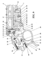
- the single-shot rifle proposed by the invention comprises a receiver (1) and a longitudinally extending barrel (6) and having a front end and a back end, said barrel (6) being attached to the receiver (1).
- the rifle comprises a bolt (8) housing a firing pin (24), the bolt (8) being located in correspondence with the back end of the barrel (6).
- the bolt (8) and the back end of the barrel (6) are configured such that the bolt (8) can be coupled to the back end of the barrel (6) by means of a sliding movement in a direction substantially perpendicular to the longitudinal direction, such that the bolt (8) can travel, by means of said sliding movement, between a loading position in which it leaves the back end of the barrel (6) clear such that a user can insert a cartridge in a chamber of the barrel (6) through said back end of the barrel (6), and a firing position in which said chamber is locked by said bolt (8), the barrel (6) and the bolt (8) being attached by means of at least one rib (61) entering at least one channel (81), such that said sliding movement is enabled and such that the bolt (8) is prevented from traveling backwards with regard to the back end of the barrel (6).
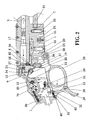
- the central supporting element of the rifle is the receiver (1), on which the barrel (6) is borne, supported or held by means of a cotter pin (25) fastened with a screw (35).
- This arrangement also allows fixing the end part of the barrel (6), as can be seen in any of Figures 2 to 10 .
- Said figures show a preferred embodiment of the rifle of the invention, in which the fixing means comprising said cotter pin (25), for the purpose of assuring that the position of the barrel (6) with regard to the receiver (1) is always the same, also obtaining precise sliding between the bolt (8) and the barrel (6), can be seen.
- the bolt (8) Located adjacent to the barrel (6) is the bolt (8), inside which the firing pin (24), which is operated by a spring (27), is housed, in a back area of the bolt (8), i.e. in an area opposite to the barrel (6).
- the stock (3) is located in the back part of the rifle, behind the receiver (1), and it can have a wide variety of configurations and materials, which can be changed and combined with the rest of the elements of the rifle by means of connecting them to the receiver (1), for example, by means of a clamping screw (55).
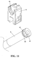
- the locking means, or locking system, of the rifle of the invention are depicted in Figures 11 and 12 .
- the bolt (8) of the rifle proposed by the invention has at least one channel (81) configured to slide on the actual barrel (6), said bolt (8) being firmly fastened to the barrel (6).
- Said rib (61) also extends around at least part of the circumference of the barrel (6), in correspondence with the back end of the barrel (6).
- the barrel (6) is provided with a solid element (7), also referred to as monobloc, for fixing the barrel (6) to the receiver (1).
- the barrel (6) is configured to be frontally introduced in the solid element (7).
- the barrel (6) comprises a flange (82), close to the rib (61), used as a stop limiting the forward exit of the barrel (6) with regard to the solid element (7).
- glue or resin is introduced for the purpose of filling the gaps that may exist between the barrel (6) and the solid element (7).
- Said solid element (7) preferably has holes for the attachment between the barrel (6) and the receiver (1) by means of screws (33), which are threaded in said holes.
- a quick and easy assembly and disassembly of the barrel (6) and the receiver (1) is thus obtained, said receiver (1) being the part housing virtually all the mechanisms of the rifle, i.e. a metal part assembled in the barrel (6) with the preferred cooperation of the cotter pin (25), which is screwed to the receiver (1).
- the barrel (6) fits into a channel existing for that purpose in the solid element (7).
- the attachment between the receiver (1) and the barrel (6) is strengthened by means of the screws (33), such that by simply loosening said screws (33) the barrel (6) is easily separated from the receiver (1), which allows then separating the barrel (6) from the bolt (8).
- the rifle comprises a handguard (2) attached to the barrel (6) by means of a pin (21) threaded in the solid element (7) and substantially extending parallel to the barrel (6), the pin (21) having a substantially conical surface which is introduced in a clip (22) in which the pin (21) is held by means of a screw (53).
- the handguard (2) also referred to as crosstree or crossguard
- the handguard (2) is located in the distal part of the rifle, i.e. in the part corresponding to the barrel (6), which is not fixed or fastened to the barrel (6), but rather is fixed to the solid element (7) by means of a pin (21) which, at its end part, has a conical area configured to receive the action of a screw (53) which is contained in the clip (22), which is in turn firmly fastened to the handguard (2).
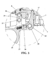
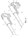
- the rifle comprises a lever (10) pivotable about an axis (38), said lever (10) being coupled to the bolt (8) for its operation, such that when the lever (10) pivots in a first direction, said lever (10) moves the bolt (8) towards the loading position, and when the lever (10) pivots in a second direction opposite to the first direction, the lever (10) moves the bolt (8) towards the firing position.
- the lever (10) has a latch (11) that swings on an axis (39) for its unlocking and its fixing, or immobilization, said latch (11) being configured to engage in a pin (45) fixed to the receiver (1) for fixing the lever (10).
- the latch (11) has a spring (31) which at one end is fixed to the lever (10) by means of a pin (40).
- the run of said latch (11) is limited by another pin (52), as has been shown, for example, in Figure 4 .
- the lever (10) is coupled to the bolt (8) by means of an attachment element (19) pivotably coupled to the bolt (8) and also pivotably coupled to the lever (10).
- the lever (10) is hingably connected to the bolt (8) by means of an attachment element (19), consisting of a chain or connecting rod having two axes, on one hand an axis (36) hinged to the bolt (8) and on the other hand an axis (37) hinged to the lever (10).
- an attachment element (19) consisting of a chain or connecting rod having two axes, on one hand an axis (36) hinged to the bolt (8) and on the other hand an axis (37) hinged to the lever (10).
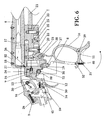
- the lever (10) is associated to an extractor (17) configured for extracting the cartridge cases, such that when said lever (10) pivots in said first direction, said lever (10) makes said extractor slide backwards (17), so that it causes the extraction of a cartridge case.
- the lever (10) is associated to said extractor (17) by means-of a pivotable arm (20), or extraction lever, engaging with the extractor (17) and being configured such that it follows the movement of the lever (10) during at least part of the run of the lever (10) between the loading position and the firing position of the bolt (8).
- the pivotable arm (20) is useful to transmit the movement of the lever (10) to the extractor (17), such that the pivotable movement of the lever (10) is converted into a linear movement of the extractor (17), during part of the run of the lever (10)
- the lever (10) thus has other additional functions.
- the first of said additional functions consists of producing or causing the ejection or extraction of the fired ammunition cartridge cases from the chamber of the barrel (6).
- the lever (10) has a bushing (23) concentric to its axis (38) configured to allow the rotation of the pivotable arm (20), also referred to as extraction lever, which is in turn configured to convert the rotational movement of the lever (10) into a translational or sliding movement of the extractor (17).
- the extraction system comprises a linear extractor (17) located under the chamber of the rifle, said extractor (17) being configured to mesh with the pivotable arm (20), in the same way a rack and pinion mechanism meshes.
- the lever (10) houses a part (58) which, at the same time as that which is described above, receives the action or thrust of the spring (57), such that said part (58) penetrates a small cavity located under the pivotable arm (20), achieving that the lever (10) and the pivotable arm (20) are temporarily attached or connected.
- the rotational movement of the pivotable arm (20) acts by making the extractor (17) slide backwards, causing the extraction of the used ammunition metal casing or cartridge case which is housed in the barrel (6).
- the extractor (17) is provided with a cartridge case extraction pin (18), which is housed in said extractor (17) and is pressed on by a spring (56), said pin (18) being configured to slide in a groove in the barrel (6) during at least part of the run of the extractor (17) and to mesh with a used cartridge case for its extraction from the chamber.
- a cartridge case extraction pin (18) which is housed in said extractor (17) and is pressed on by a spring (56), said pin (18) being configured to slide in a groove in the barrel (6) during at least part of the run of the extractor (17) and to mesh with a used cartridge case for its extraction from the chamber.
- the back part of said extractor (17) has a pin (18) acted or pressed on by the spring (56), engaging in an extraction groove of the back part of the used ammunition cartridge case.
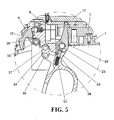
- the rifle comprises a sear element (13) pushed by a sear spring (30) towards a position in which it engages a trigger (14), as well as a safety element (16) that can travel between a position in which it prevents the firing of the rifle and another position in which it does not prevent the firing of the rifle, the safety element (16) being drawn towards the position in which it prevents the firing of the rifle by a safety spring (26), the safety element (16) and the sear element (13) being arranged such that when the bolt (8) travels towards the loading position, the sear element (13) pushed by the sear spring (30) is moved, is moved, allowing the safety element (16) to travel to the position in which it prevents the firing of the rifle.
- a second additional function of the lever (10) is to automatically cock, activate or load the percussion means or system.
- the sear element (13) moves and drops down, acted on or driven by the sear spring (30).
- the safety element (16) is released and automatically flies out backwards due to the effect or the actuation of the safety spring (26), the action of which is opposite to the action of the sear spring (30), such that the rifle is in a safety or locked position, position which is shown in Figure 8 .
- the safety element (16) is located on the receiver (1) of the rifle in an easy access position for the thumb of the hand the user is firing with, enabling ambidextrous use.
- Said safety element (16) is configured to be placed, or activated, and removed, or deactivated, by the user, having the particularity that said safety element (16) is always automatically located in the active position when the bolt (8) is unlocked to load or unload the weapon, preventing in said active safety position the firing of the rifle.
- the safety element (16) has a safety spring (26) which pulls on said safety element (16) as soon as the sear element (13) is released from the hammer (12), i.e. when the lever (10) is lowered. Therefore, when said lever (10) moves up for the purpose of compressing the percussion spring (27), the safety element (16) is already acting, i.e. it is already activated, as can be seen in Figures 6 and 8 . In short, in order to fire it is always necessary for the user to voluntarily remove the safety, placing it in the inactive position, as shown in Figures 9 and 2 .
- the rifle comprises a highly sensitive trigger (14) provided with dual-regulation.
- the lower part of the trigger (14) has an adjusting screw (50) which, by means of tightening it, achieves that the trigger (14) recoils, therefore the engagement of the upper area with the sear element (13) is reduced, and therefore the trigger is attenuated.
- the rifle has the end stop adjusting screw (59), which runs inside the trigger spring, which decreases or reduces the run of the trigger (14) by means of tightening it.
- the sear element (13) is arranged such that when the bolt (8) travels towards its loading position, the sear element (13) engages with the trigger (14).
- the rifle comprises a hammer (12) configured to strike the firing pin (24) when the trigger (14) is squeezed with the safety element (16) in the position in which it does not prevent the firing of the rifle, the hammer (12) being pivotably attached to the bolt (8) such that it travels with the bolt (8) when the bolt (8) travels between the firing position and the loading position.
- the hammer (12) is located inside the bolt (8) and is configured to strike the firing pin (24), such that said firing pin (24) in turn acts on an ammunition percussion cap causing its detonation.
- the hammer (12) is linked to the sear element (13) such that is retained by the sear element (13) when the bolt (8) travels from the loading position towards the firing position, such that when the bolt (8) reaches the firing position, the hammer (12) is cocked to be fired towards the firing pin (24).
- the single-shot rifle also comprises a fire protection element (9) associated to the bolt (8) and configured to deflect sparks coming out backwards at the moment of firing.
- the bolt (8) is locked with the fire protection element (9), also referred to as safety deflector, consisting of a steel part which is fastened to the bolt (8) by a screw (34).
- the bolt (8) internally has the hammer (12) which is configured to rotate with regard to an axis (51) of hammer (12) and to be actuated by a main spring (28) as can be seen, for example, in Figure 2 .
- the firing pin (24) perforates the primer when firing, causing a high-pressure backfire towards the shooter through the firing pin passage, specifically towards the shooter's face and eyes, with the subsequent risk of a serious accident that this entails.
- the rifle comprises a fire protection element (9), i.e. a safety deflector consisting of a steel part firmly fastened to the bolt (8), said fire protection element (9) being configured to deflect the backfire occurring when firing towards inner areas, with lower exhaust, of the receiver (1), making said bolt (8) lose pressure and thus preventing the previously discussed accidents.
- a fire protection element (9) i.e. a safety deflector consisting of a steel part firmly fastened to the bolt (8), said fire protection element (9) being configured to deflect the backfire occurring when firing towards inner areas, with lower exhaust, of the receiver (1), making said bolt (8) lose pressure and thus preventing the previously discussed accidents.
- the fire protection element (9) comprises a deflection surface, configured to deflect sparks towards the inside of the receiver (1), preventing them from reaching the user's eyes.
- Said deflection surface is preferably configured such that it forms, in the vertical plane traversing the barrel (6) when the rifle is in a conventional use position, an angle of approximately 45 degrees with the longitudinal direction in which the barrel (6) extends.
- the fire protection element (9) comprises an inclined plane, preferably occupying a 45° inclination when the rifle is in a firing position, which is located opposite to the passage of the firing pin (24), such that by means of this arrangement the sparks bounce off and are guided downwards, avoiding striking the face of the user of the rifle.
Landscapes
- Engineering & Computer Science (AREA)
- General Engineering & Computer Science (AREA)
- Aiming, Guidance, Guns With A Light Source, Armor, Camouflage, And Targets (AREA)
- Telescopes (AREA)
- Glass Compositions (AREA)
- Saccharide Compounds (AREA)
- Crystals, And After-Treatments Of Crystals (AREA)
Claims (18)
- Carabine à simple coup, comprenant :une boîte de culasse (1),un canon (6) s'étendant longitudinalement et ayant une extrémité avant et une extrémité arrière, le canon (6) étant fixé sur la boîte de culasse (1) ;une culasse (8) logeant un percuteur (24), la culasse (8) étant positionnée en correspondance avec l'extrémité arrière du canon (6) ;dans laquelle :la culasse (8) et l'extrémité arrière du canon (6) sont configurées de sorte que la culasse (8) puisse être couplée à l'extrémité arrière du canon (6) au moyen d'un mouvement de coulissement dans une direction sensiblement perpendiculaire à la direction longitudinale, de sorte que la culasse (8) puisse se déplacer, au moyen dudit mouvement coulissant, entre une position de chargement dans laquelle elle quitte l'extrémité arrière du canon (6) de sorte qu'un utilisateur puisse insérer une cartouche dans une chambre du canon (6) par ladite extrémité arrière du canon (6), et une position de tir dans laquelle ladite chambre est bloquée par ladite culasse (8), le canon (6) et la culasse (8) étant fixés au moyen d'au moins d'une nervure (61) qui entre dans au moins un canal (81), de sorte que ledit mouvement de coulissement soit autorisé et de sorte que l'on empêche la culasse (8) de se déplacer vers l'arrière par rapport à l'extrémité arrière du canon (6) ;dans laquelle :le canon (6), en correspondance avec son extrémité arrière, est muni d'un élément solide (7) pour fixer le canon (6) sur la boîte de culasse (1),et dans laquelle le canon (6), en correspondance avec son extrémité arrière, comprend au moins un manche à air (82), configuré pour être utilisé en tant que butée pour limiter la position de l'élément solide (7), ledit canon (6) étant configuré pour être introduit de face dans ledit élément solide (7).
- Carabine à simple coup selon la revendication 1, dans laquelle ladite au moins une nervure (61) comprend au moins une nervure (61) positionnée dans l'extrémité arrière du canon (6), et dans laquelle ledit au moins un canal (81) comprend au moins un canal (81) positionné dans la culasse (8) et configuré pour recevoir ladite au moins une nervure (61), de sorte qu'avec ladite au moins une nervure (61) logée dans ledit au moins un canal (81), la culasse (8) soit fixée sur le canon (6) de sorte qu'elle ne puisse pas reculer par rapport au canon (6), mais de sorte qu'elle puisse se déplacer dans une direction sensiblement perpendiculaire au canon (6), au moyen du coulissement de ladite au moins une nervure (61) dans ledit au moins un canal (81).
- Carabine à simple coup selon la revendication 1 ou 2, dans laquelle ladite au moins une nervure (61) comprend au moins deux nervures (61) et dans laquelle ledit au moins un canal (81) comprend au moins deux canaux (81).
- Carabine à simple coup selon l'une quelconque des revendications précédentes, dans laquelle ladite au moins une nervure (61) s'étend autour d'au moins une partie de la circonférence du canon (6) en correspondance avec l'extrémité arrière du canon (6).
- Carabine à simple coup selon l'une quelconque des revendications précédentes, dans laquelle l'élément solide (7) a des trous pour la fixation entre le canon (6) et la boîte de culasse (1) au moyen de vis (33) qui sont vissées dans lesdits trous.
- Carabine à simple coup selon l'une quelconque des revendications précédentes, comprenant de plus un protège-mains (2) fixé sur le canon (6) au moyen d'une broche (21) vissée dans l'élément solide (7) et s'étendant sensiblement parallèlement au canon (6), la broche (21) ayant une surface sensiblement conique qui est introduite dans un chargeur de magasin (22) dans laquelle la broche (21) est maintenue au moyen d'une vis (53).
- Carabine à simple coup selon l'une quelconque des revendications précédentes, comprenant de plus au moins un levier (10) pouvant pivoter autour d'un axe (38), ledit levier (10) étant couplé à la culasse (8) de sorte que lorsque le levier (10) pivote dans une première direction, ledit levier (10) déplace la culasse (8) vers la position de chargement, et lorsque le levier (10) pivote dans une seconde direction opposée à la première direction, le levier (10) déplace la culasse (8) vers la position de tir.
- Carabine à simple coup selon la revendication 7, dans laquelle ledit levier (10) est couplé à la culasse (8) au moyen d'un élément de fixation (19) couplé de manière pivotante à la culasse (8) et également couplé de manière pivotante au levier (10).
- Carabine à simple coup selon l'une quelconque des revendications 7 à 8, dans laquelle ledit levier (10) est associé à un extracteur (17) configuré pour extraire les douilles, de sorte que lorsque ledit levier (10) pivote dans ladite première direction, ledit levier (10) fasse coulisser ledit extracteur (17) vers l'arrière de sorte qu'il provoque l'extraction d'une douille.
- Carabine à simple coup selon la revendication 9, dans laquelle ledit levier (10) est associé audit extracteur (17) au moyen d'un bras pivotant (20) s'engrenant avec l'extracteur (17) et étant configuré de sorte qu'il suive le mouvement du levier (10) pendant au moins une partie de la course du levier (10) entre la position de chargement et la position de tir de la culasse (8).
- Carabine à simple coup selon l'une quelconque des revendications 9 et 10, dans laquelle l'extracteur (17) est muni d'une broche (18) comprimée par un ressort (56), ladite broche (18) étant configurée pour coulisser dans une rainure dans le canon (6) pendant au moins une partie de la course de l'extracteur (17) et pour s'engrener avec une douille usagée pour son extraction de la chambre.
- Carabine à simple coup selon l'une quelconque des revendications précédentes, comprenant en outre un élément formant levier d'armement (13) poussé par un ressort de levier d'armement (30) vers une position dans laquelle il met en prise une gâchette (14) ainsi qu'un élément de sécurité (16) qui peut se déplacer entre une position dans laquelle il empêche le tir de la carabine et une autre position dans laquelle il n'empêche pas le tir de la carabine, l'élément de sécurité (16) étant tiré vers la position dans laquelle il empêche le tir de la carabine par un ressort de sécurité (26), l'élément de sécurité (16) et l'élément formant levier d'armement (13) étant agencés de sorte que lorsque la culasse (8) se déplace vers la position de chargement, l'élément formant levier d'armement (13) poussé par le ressort de levier d'armement (30) se déplace, permettant à l'élément de sécurité (16) de se déplacer vers la position dans laquelle il empêche le tir de la carabine.
- Carabine à simple coup selon la revendication 12, dans laquelle l'élément formant levier d'armement (13) est agencé de sorte que lorsque la culasse (8) se déplace vers sa position de chargement, l'élément formant levier d'armement (13) mette en prise la gâchette (14).
- Carabine à simple coup selon la revendication 13, comprenant de plus un marteau (12) configuré pour frapper le percuteur (24) lorsque la gâchette (14) est comprimée avec l'élément de sécurité (16) dans la position dans laquelle il n'empêche pas le tir de la carabine, le marteau (12) étant fixé de manière pivotante sur la culasse (8) de sorte qu'il se déplace avec la culasse (8) lorsque la culasse (8) se déplace entre la position de tir et la position de chargement.
- Carabine à simple coup selon la revendication 14, dans laquelle le marteau (12) est raccordé à l'élément formant levier d'armement (13) de sorte qu'il soit retenu par l'élément formant levier d'armement (13) lorsque la culasse (8) se déplace de la position de chargement à la position de tir, de sorte que lorsque la culasse (8) atteint la position de tir, le marteau (12) soit armé pour être tiré vers le percuteur (24).
- Carabine à simple coup selon l'une quelconque des revendications précédentes, comprenant de plus, un élément de protection de tir (9) associé à la culasse (8) et configuré pour dévier les étincelles qui sortent vers l'arrière au moment du tir.
- Carabine à simple coup selon la revendication 16, dans laquelle ledit élément de protection de tir (9) comprend une surface de déflexion configurée pour dévier les étincelles vers l'intérieur de la boîte de culasse (1), les empêchant d'atteindre les yeux de l'utilisateur.
- Carabine à simple coup selon la revendication 17, ladite surface de déflexion étant configurée de sorte qu'elle forme, dans le plan vertical traversant le canon (6) lorsque la carabine est dans une position d'utilisation classique, un angle d'approximativement 45 degrés avec la direction longitudinale dans laquelle le canon (6) s'étend.
Priority Applications (4)
| Application Number | Priority Date | Filing Date | Title |
|---|---|---|---|
| AT07380285T ATE476632T1 (de) | 2007-10-22 | 2007-10-22 | Einzelladergewehr |
| DE602007008254T DE602007008254D1 (de) | 2007-10-22 | 2007-10-22 | Einzelladergewehr |
| ES07380285T ES2350375T3 (es) | 2007-10-22 | 2007-10-22 | Rifle monotiro. |
| EP07380285A EP2053336B1 (fr) | 2007-10-22 | 2007-10-22 | Carabine à un coup |
Applications Claiming Priority (1)
| Application Number | Priority Date | Filing Date | Title |
|---|---|---|---|
| EP07380285A EP2053336B1 (fr) | 2007-10-22 | 2007-10-22 | Carabine à un coup |
Publications (2)
| Publication Number | Publication Date |
|---|---|
| EP2053336A1 EP2053336A1 (fr) | 2009-04-29 |
| EP2053336B1 true EP2053336B1 (fr) | 2010-08-04 |
Family
ID=39259570
Family Applications (1)
| Application Number | Title | Priority Date | Filing Date |
|---|---|---|---|
| EP07380285A Active EP2053336B1 (fr) | 2007-10-22 | 2007-10-22 | Carabine à un coup |
Country Status (4)
| Country | Link |
|---|---|
| EP (1) | EP2053336B1 (fr) |
| AT (1) | ATE476632T1 (fr) |
| DE (1) | DE602007008254D1 (fr) |
| ES (1) | ES2350375T3 (fr) |
Cited By (2)
| Publication number | Priority date | Publication date | Assignee | Title |
|---|---|---|---|---|
| US8985005B1 (en) | 2013-12-19 | 2015-03-24 | Smith & Wesson Corp. | Repeating firearm |
| RU2787065C1 (ru) * | 2022-10-10 | 2022-12-28 | Закрытое акционерное общество "Техкрим" | Огнестрельное оружие |
Family Cites Families (5)
| Publication number | Priority date | Publication date | Assignee | Title |
|---|---|---|---|---|
| US592239A (en) * | 1897-10-26 | Shell-ejecting device for firearms | ||
| US511633A (en) * | 1893-12-26 | William mason | ||
| US2445339A (en) * | 1946-09-11 | 1948-07-20 | Summerbell William | Gun tube, breech ring, and coupling means therefor |
| US3355833A (en) * | 1966-05-16 | 1967-12-05 | Strum Ruger & Co Inc | Single shot drop breechblock rifle |
| US4040196A (en) * | 1976-05-17 | 1977-08-09 | Triple-S Development Co., Inc. | Rifle |
-
2007
- 2007-10-22 EP EP07380285A patent/EP2053336B1/fr active Active
- 2007-10-22 AT AT07380285T patent/ATE476632T1/de active
- 2007-10-22 ES ES07380285T patent/ES2350375T3/es active Active
- 2007-10-22 DE DE602007008254T patent/DE602007008254D1/de active Active
Cited By (3)
| Publication number | Priority date | Publication date | Assignee | Title |
|---|---|---|---|---|
| US8985005B1 (en) | 2013-12-19 | 2015-03-24 | Smith & Wesson Corp. | Repeating firearm |
| RU2787065C1 (ru) * | 2022-10-10 | 2022-12-28 | Закрытое акционерное общество "Техкрим" | Огнестрельное оружие |
| RU225827U1 (ru) * | 2024-03-28 | 2024-05-07 | Акционерное общество "Концерн "Калашников" | Однозарядное оружие |
Also Published As
| Publication number | Publication date |
|---|---|
| ATE476632T1 (de) | 2010-08-15 |
| DE602007008254D1 (de) | 2010-09-16 |
| ES2350375T3 (es) | 2011-01-21 |
| EP2053336A1 (fr) | 2009-04-29 |
Similar Documents
| Publication | Publication Date | Title |
|---|---|---|
| US5149898A (en) | Fire control assembly | |
| US4703826A (en) | Polymer gun | |
| US6604311B1 (en) | Lever-operated breechblock for muzzle-loading firearm | |
| EP3129739B1 (fr) | Système de commande de tir pour armes à feu | |
| US7261029B1 (en) | Firearm bolt locking mechanism | |
| US11274890B2 (en) | Advanced gas piston system | |
| US7302881B1 (en) | Conversion kit and method for a ruger 10/22 semi-automatic .22 caliber rim fire rifle to shoot .17 mach 2 cartridges | |
| US7735409B1 (en) | Conversion kit and method for a RUGER® 10/22® semi-automatic .22 caliber rim fire gun to shoot .17 mach 2 cartridges | |
| US5454182A (en) | Black powder firearm | |
| US5272957A (en) | Firearm with plastic material | |
| US11112199B2 (en) | Slide action rifle with a bolt carrier locking mechanism external to the receiver | |
| US10247500B2 (en) | Modular bolt assembly with floating fire pin | |
| US20090101000A1 (en) | Bolt head locking arrangement for firearm weapons | |
| KR20080096658A (ko) | 슬라이드-후퇴 레버를 구비한 휴대용 화기 | |
| US7574951B2 (en) | Single-shot rifle | |
| US20050229463A1 (en) | Firearm assembly | |
| US4909129A (en) | Gun lock and gas operating system | |
| RU2307992C1 (ru) | Боевое пневматическое короткоствольное оружие (варианты) | |
| US7353742B1 (en) | Double action firing pin system | |
| US4947730A (en) | Firing mechanism for polymer weapon apparatus | |
| EP2053336B1 (fr) | Carabine à un coup | |
| US5517897A (en) | Semi-automatic handgun with unalterable trigger mechanism | |
| US20060207147A1 (en) | Self-contained triggerplate action for low profile firearms | |
| US4926739A (en) | Polymer gun operating handle | |
| EP0057733A1 (fr) | Arme à feu portative semi-automatique |
Legal Events
| Date | Code | Title | Description |
|---|---|---|---|
| PUAI | Public reference made under article 153(3) epc to a published international application that has entered the european phase |
Free format text: ORIGINAL CODE: 0009012 |
|
| AK | Designated contracting states |
Kind code of ref document: A1 Designated state(s): AT BE BG CH CY CZ DE DK EE ES FI FR GB GR HU IE IS IT LI LT LU LV MC MT NL PL PT RO SE SI SK TR |
|
| AX | Request for extension of the european patent |
Extension state: AL BA HR MK RS |
|
| 17P | Request for examination filed |
Effective date: 20091006 |
|
| AKX | Designation fees paid |
Designated state(s): AT BE BG CH CY CZ DE DK EE ES FI FR GB GR HU IE IS IT LI LT LU LV MC MT NL PL PT RO SE SI SK TR |
|
| GRAP | Despatch of communication of intention to grant a patent |
Free format text: ORIGINAL CODE: EPIDOSNIGR1 |
|
| GRAS | Grant fee paid |
Free format text: ORIGINAL CODE: EPIDOSNIGR3 |
|
| GRAA | (expected) grant |
Free format text: ORIGINAL CODE: 0009210 |
|
| AK | Designated contracting states |
Kind code of ref document: B1 Designated state(s): AT BE BG CH CY CZ DE DK EE ES FI FR GB GR HU IE IS IT LI LT LU LV MC MT NL PL PT RO SE SI SK TR |
|
| REG | Reference to a national code |
Ref country code: GB Ref legal event code: FG4D |
|
| REG | Reference to a national code |
Ref country code: CH Ref legal event code: EP |
|
| REG | Reference to a national code |
Ref country code: IE Ref legal event code: FG4D |
|
| REF | Corresponds to: |
Ref document number: 602007008254 Country of ref document: DE Date of ref document: 20100916 Kind code of ref document: P |
|
| REG | Reference to a national code |
Ref country code: NL Ref legal event code: VDEP Effective date: 20100804 |
|
| REG | Reference to a national code |
Ref country code: ES Ref legal event code: FG2A Effective date: 20110111 |
|
| LTIE | Lt: invalidation of european patent or patent extension |
Effective date: 20100804 |
|
| PG25 | Lapsed in a contracting state [announced via postgrant information from national office to epo] |
Ref country code: LT Free format text: LAPSE BECAUSE OF FAILURE TO SUBMIT A TRANSLATION OF THE DESCRIPTION OR TO PAY THE FEE WITHIN THE PRESCRIBED TIME-LIMIT Effective date: 20100804 Ref country code: NL Free format text: LAPSE BECAUSE OF FAILURE TO SUBMIT A TRANSLATION OF THE DESCRIPTION OR TO PAY THE FEE WITHIN THE PRESCRIBED TIME-LIMIT Effective date: 20100804 Ref country code: FI Free format text: LAPSE BECAUSE OF FAILURE TO SUBMIT A TRANSLATION OF THE DESCRIPTION OR TO PAY THE FEE WITHIN THE PRESCRIBED TIME-LIMIT Effective date: 20100804 |
|
| PG25 | Lapsed in a contracting state [announced via postgrant information from national office to epo] |
Ref country code: CY Free format text: LAPSE BECAUSE OF FAILURE TO SUBMIT A TRANSLATION OF THE DESCRIPTION OR TO PAY THE FEE WITHIN THE PRESCRIBED TIME-LIMIT Effective date: 20100804 Ref country code: SI Free format text: LAPSE BECAUSE OF FAILURE TO SUBMIT A TRANSLATION OF THE DESCRIPTION OR TO PAY THE FEE WITHIN THE PRESCRIBED TIME-LIMIT Effective date: 20100804 Ref country code: PL Free format text: LAPSE BECAUSE OF FAILURE TO SUBMIT A TRANSLATION OF THE DESCRIPTION OR TO PAY THE FEE WITHIN THE PRESCRIBED TIME-LIMIT Effective date: 20100804 Ref country code: PT Free format text: LAPSE BECAUSE OF FAILURE TO SUBMIT A TRANSLATION OF THE DESCRIPTION OR TO PAY THE FEE WITHIN THE PRESCRIBED TIME-LIMIT Effective date: 20101206 Ref country code: IS Free format text: LAPSE BECAUSE OF FAILURE TO SUBMIT A TRANSLATION OF THE DESCRIPTION OR TO PAY THE FEE WITHIN THE PRESCRIBED TIME-LIMIT Effective date: 20101204 Ref country code: BG Free format text: LAPSE BECAUSE OF FAILURE TO SUBMIT A TRANSLATION OF THE DESCRIPTION OR TO PAY THE FEE WITHIN THE PRESCRIBED TIME-LIMIT Effective date: 20101104 |
|
| PG25 | Lapsed in a contracting state [announced via postgrant information from national office to epo] |
Ref country code: BE Free format text: LAPSE BECAUSE OF FAILURE TO SUBMIT A TRANSLATION OF THE DESCRIPTION OR TO PAY THE FEE WITHIN THE PRESCRIBED TIME-LIMIT Effective date: 20100804 Ref country code: LV Free format text: LAPSE BECAUSE OF FAILURE TO SUBMIT A TRANSLATION OF THE DESCRIPTION OR TO PAY THE FEE WITHIN THE PRESCRIBED TIME-LIMIT Effective date: 20100804 Ref country code: SE Free format text: LAPSE BECAUSE OF FAILURE TO SUBMIT A TRANSLATION OF THE DESCRIPTION OR TO PAY THE FEE WITHIN THE PRESCRIBED TIME-LIMIT Effective date: 20100804 |
|
| PG25 | Lapsed in a contracting state [announced via postgrant information from national office to epo] |
Ref country code: DK Free format text: LAPSE BECAUSE OF FAILURE TO SUBMIT A TRANSLATION OF THE DESCRIPTION OR TO PAY THE FEE WITHIN THE PRESCRIBED TIME-LIMIT Effective date: 20100804 |
|
| PG25 | Lapsed in a contracting state [announced via postgrant information from national office to epo] |
Ref country code: IT Free format text: LAPSE BECAUSE OF FAILURE TO SUBMIT A TRANSLATION OF THE DESCRIPTION OR TO PAY THE FEE WITHIN THE PRESCRIBED TIME-LIMIT Effective date: 20100804 Ref country code: EE Free format text: LAPSE BECAUSE OF FAILURE TO SUBMIT A TRANSLATION OF THE DESCRIPTION OR TO PAY THE FEE WITHIN THE PRESCRIBED TIME-LIMIT Effective date: 20100804 Ref country code: SK Free format text: LAPSE BECAUSE OF FAILURE TO SUBMIT A TRANSLATION OF THE DESCRIPTION OR TO PAY THE FEE WITHIN THE PRESCRIBED TIME-LIMIT Effective date: 20100804 Ref country code: CZ Free format text: LAPSE BECAUSE OF FAILURE TO SUBMIT A TRANSLATION OF THE DESCRIPTION OR TO PAY THE FEE WITHIN THE PRESCRIBED TIME-LIMIT Effective date: 20100804 Ref country code: MC Free format text: LAPSE BECAUSE OF NON-PAYMENT OF DUE FEES Effective date: 20101031 Ref country code: RO Free format text: LAPSE BECAUSE OF FAILURE TO SUBMIT A TRANSLATION OF THE DESCRIPTION OR TO PAY THE FEE WITHIN THE PRESCRIBED TIME-LIMIT Effective date: 20100804 |
|
| PLBE | No opposition filed within time limit |
Free format text: ORIGINAL CODE: 0009261 |
|
| STAA | Information on the status of an ep patent application or granted ep patent |
Free format text: STATUS: NO OPPOSITION FILED WITHIN TIME LIMIT |
|
| 26N | No opposition filed |
Effective date: 20110506 |
|
| PG25 | Lapsed in a contracting state [announced via postgrant information from national office to epo] |
Ref country code: FR Free format text: LAPSE BECAUSE OF NON-PAYMENT OF DUE FEES Effective date: 20101102 |
|
| REG | Reference to a national code |
Ref country code: FR Ref legal event code: ST Effective date: 20110630 |
|
| REG | Reference to a national code |
Ref country code: DE Ref legal event code: R097 Ref document number: 602007008254 Country of ref document: DE Effective date: 20110506 |
|
| PG25 | Lapsed in a contracting state [announced via postgrant information from national office to epo] |
Ref country code: IE Free format text: LAPSE BECAUSE OF NON-PAYMENT OF DUE FEES Effective date: 20101022 |
|
| PG25 | Lapsed in a contracting state [announced via postgrant information from national office to epo] |
Ref country code: MT Free format text: LAPSE BECAUSE OF FAILURE TO SUBMIT A TRANSLATION OF THE DESCRIPTION OR TO PAY THE FEE WITHIN THE PRESCRIBED TIME-LIMIT Effective date: 20100804 |
|
| REG | Reference to a national code |
Ref country code: CH Ref legal event code: PL |
|
| GBPC | Gb: european patent ceased through non-payment of renewal fee |
Effective date: 20111022 |
|
| PG25 | Lapsed in a contracting state [announced via postgrant information from national office to epo] |
Ref country code: CH Free format text: LAPSE BECAUSE OF NON-PAYMENT OF DUE FEES Effective date: 20111031 Ref country code: LI Free format text: LAPSE BECAUSE OF NON-PAYMENT OF DUE FEES Effective date: 20111031 |
|
| PG25 | Lapsed in a contracting state [announced via postgrant information from national office to epo] |
Ref country code: GB Free format text: LAPSE BECAUSE OF NON-PAYMENT OF DUE FEES Effective date: 20111022 |
|
| PG25 | Lapsed in a contracting state [announced via postgrant information from national office to epo] |
Ref country code: HU Free format text: LAPSE BECAUSE OF FAILURE TO SUBMIT A TRANSLATION OF THE DESCRIPTION OR TO PAY THE FEE WITHIN THE PRESCRIBED TIME-LIMIT Effective date: 20110205 Ref country code: LU Free format text: LAPSE BECAUSE OF NON-PAYMENT OF DUE FEES Effective date: 20101022 |
|
| PG25 | Lapsed in a contracting state [announced via postgrant information from national office to epo] |
Ref country code: TR Free format text: LAPSE BECAUSE OF FAILURE TO SUBMIT A TRANSLATION OF THE DESCRIPTION OR TO PAY THE FEE WITHIN THE PRESCRIBED TIME-LIMIT Effective date: 20100804 |
|
| PGFP | Annual fee paid to national office [announced via postgrant information from national office to epo] |
Ref country code: DE Payment date: 20121025 Year of fee payment: 6 |
|
| PGFP | Annual fee paid to national office [announced via postgrant information from national office to epo] |
Ref country code: AT Payment date: 20121030 Year of fee payment: 6 |
|
| REG | Reference to a national code |
Ref country code: AT Ref legal event code: MM01 Ref document number: 476632 Country of ref document: AT Kind code of ref document: T Effective date: 20131022 |
|
| REG | Reference to a national code |
Ref country code: DE Ref legal event code: R119 Ref document number: 602007008254 Country of ref document: DE Effective date: 20140501 |
|
| PG25 | Lapsed in a contracting state [announced via postgrant information from national office to epo] |
Ref country code: GR Free format text: LAPSE BECAUSE OF FAILURE TO SUBMIT A TRANSLATION OF THE DESCRIPTION OR TO PAY THE FEE WITHIN THE PRESCRIBED TIME-LIMIT Effective date: 20100804 Ref country code: AT Free format text: LAPSE BECAUSE OF NON-PAYMENT OF DUE FEES Effective date: 20131022 Ref country code: DE Free format text: LAPSE BECAUSE OF NON-PAYMENT OF DUE FEES Effective date: 20140501 |
|
| PGFP | Annual fee paid to national office [announced via postgrant information from national office to epo] |
Ref country code: ES Payment date: 20231106 Year of fee payment: 17 |